EP3299581A1 - Gas turbine engine - Google Patents
Gas turbine engine Download PDFInfo
- Publication number
- EP3299581A1 EP3299581A1 EP17187010.8A EP17187010A EP3299581A1 EP 3299581 A1 EP3299581 A1 EP 3299581A1 EP 17187010 A EP17187010 A EP 17187010A EP 3299581 A1 EP3299581 A1 EP 3299581A1
- Authority
- EP
- European Patent Office
- Prior art keywords
- disc
- blade
- blade root
- gas turbine
- turbine engine
- Prior art date
- Legal status (The legal status is an assumption and is not a legal conclusion. Google has not performed a legal analysis and makes no representation as to the accuracy of the status listed.)
- Withdrawn
Links
- 230000014759 maintenance of location Effects 0.000 description 11
- 238000002485 combustion reaction Methods 0.000 description 3
- 238000003754 machining Methods 0.000 description 3
- 238000000034 method Methods 0.000 description 3
- 230000001141 propulsive effect Effects 0.000 description 3
- 238000005097 cold rolling Methods 0.000 description 2
- 238000004519 manufacturing process Methods 0.000 description 2
- 230000008569 process Effects 0.000 description 2
- 230000006835 compression Effects 0.000 description 1
- 238000007906 compression Methods 0.000 description 1
- 238000005242 forging Methods 0.000 description 1
- 239000000446 fuel Substances 0.000 description 1
- 239000000463 material Substances 0.000 description 1
- 239000000203 mixture Substances 0.000 description 1
- 238000012986 modification Methods 0.000 description 1
- 230000004048 modification Effects 0.000 description 1
- 238000005480 shot peening Methods 0.000 description 1
- 239000007787 solid Substances 0.000 description 1
- 230000007704 transition Effects 0.000 description 1
- 239000002699 waste material Substances 0.000 description 1
Images

Classifications
-
- F—MECHANICAL ENGINEERING; LIGHTING; HEATING; WEAPONS; BLASTING
- F01—MACHINES OR ENGINES IN GENERAL; ENGINE PLANTS IN GENERAL; STEAM ENGINES
- F01D—NON-POSITIVE DISPLACEMENT MACHINES OR ENGINES, e.g. STEAM TURBINES
- F01D5/00—Blades; Blade-carrying members; Heating, heat-insulating, cooling or antivibration means on the blades or the members
- F01D5/30—Fixing blades to rotors; Blade roots ; Blade spacers
- F01D5/32—Locking, e.g. by final locking blades or keys
- F01D5/326—Locking of axial insertion type blades by other means
-
- F—MECHANICAL ENGINEERING; LIGHTING; HEATING; WEAPONS; BLASTING
- F01—MACHINES OR ENGINES IN GENERAL; ENGINE PLANTS IN GENERAL; STEAM ENGINES
- F01D—NON-POSITIVE DISPLACEMENT MACHINES OR ENGINES, e.g. STEAM TURBINES
- F01D5/00—Blades; Blade-carrying members; Heating, heat-insulating, cooling or antivibration means on the blades or the members
- F01D5/30—Fixing blades to rotors; Blade roots ; Blade spacers
- F01D5/3023—Fixing blades to rotors; Blade roots ; Blade spacers of radial insertion type, e.g. in individual recesses
- F01D5/303—Fixing blades to rotors; Blade roots ; Blade spacers of radial insertion type, e.g. in individual recesses in a circumferential slot
-
- F—MECHANICAL ENGINEERING; LIGHTING; HEATING; WEAPONS; BLASTING
- F01—MACHINES OR ENGINES IN GENERAL; ENGINE PLANTS IN GENERAL; STEAM ENGINES
- F01D—NON-POSITIVE DISPLACEMENT MACHINES OR ENGINES, e.g. STEAM TURBINES
- F01D5/00—Blades; Blade-carrying members; Heating, heat-insulating, cooling or antivibration means on the blades or the members
- F01D5/30—Fixing blades to rotors; Blade roots ; Blade spacers
- F01D5/3023—Fixing blades to rotors; Blade roots ; Blade spacers of radial insertion type, e.g. in individual recesses
- F01D5/3046—Fixing blades to rotors; Blade roots ; Blade spacers of radial insertion type, e.g. in individual recesses the rotor having ribs around the circumference
-
- F—MECHANICAL ENGINEERING; LIGHTING; HEATING; WEAPONS; BLASTING
- F05—INDEXING SCHEMES RELATING TO ENGINES OR PUMPS IN VARIOUS SUBCLASSES OF CLASSES F01-F04
- F05D—INDEXING SCHEME FOR ASPECTS RELATING TO NON-POSITIVE-DISPLACEMENT MACHINES OR ENGINES, GAS-TURBINES OR JET-PROPULSION PLANTS
- F05D2220/00—Application
- F05D2220/30—Application in turbines
- F05D2220/36—Application in turbines specially adapted for the fan of turbofan engines
-
- F—MECHANICAL ENGINEERING; LIGHTING; HEATING; WEAPONS; BLASTING
- F05—INDEXING SCHEMES RELATING TO ENGINES OR PUMPS IN VARIOUS SUBCLASSES OF CLASSES F01-F04
- F05D—INDEXING SCHEME FOR ASPECTS RELATING TO NON-POSITIVE-DISPLACEMENT MACHINES OR ENGINES, GAS-TURBINES OR JET-PROPULSION PLANTS
- F05D2240/00—Components
- F05D2240/20—Rotors
-
- F—MECHANICAL ENGINEERING; LIGHTING; HEATING; WEAPONS; BLASTING
- F05—INDEXING SCHEMES RELATING TO ENGINES OR PUMPS IN VARIOUS SUBCLASSES OF CLASSES F01-F04
- F05D—INDEXING SCHEME FOR ASPECTS RELATING TO NON-POSITIVE-DISPLACEMENT MACHINES OR ENGINES, GAS-TURBINES OR JET-PROPULSION PLANTS
- F05D2260/00—Function
- F05D2260/30—Retaining components in desired mutual position
Definitions
- the present disclosure concerns a fan blade and/or a gas turbine engine.
- Gas turbine engines are typically employed to power aircraft.
- a gas turbine engine will comprise an axial fan driven by an engine core.
- the engine core is generally made up of one or more turbines which drive respective compressors via coaxial shafts.
- the fan is usually driven off an additional lower pressure turbine in the engine core.
- the fan includes a plurality of fan blades arranged around a disc.
- the blades may be integrally formed with the disc or the blades and disc may be formed separately, and a blade root of the blades may be received in a complimentary slot in the disc.
- the blade root and slot of the disc may have any suitable shape, but are often dovetail shaped.
- the fan blade root 126 includes a groove 128 which receives a U-shaped key member 130.
- the key member is connected to the blade root using a strap 132 that is connected, e.g. using two pins, to the blade root.
- a disc for use with the blade of Figures 1A and 1B includes an axially extending slot for receiving the blade root.
- a groove is also provided in the disc and circumferentially extends from the slot. The groove is positioned so as to receive the key member 130 when the blade root is received in the slot of the disc.
- a sprung member 140 and a slider 142 are provided to fix the blade with respect to the disc.
- the key member 130 is connected to the blade root.
- the blade root and key member are then slide into the slot of the disc, so that the key member is axially aligned with the respective grooves of the disc.
- the spring member 140 is provided in the slot of the disc, and the slider 142 is moved into the slot so as to cause the spring member to bias the key member into the grooves of the disc.
- a gas turbine engine comprising a disc having a disc slot (e.g. a plurality of disc slots) and a circumferential groove extending from the slot.
- a blade e.g. a plurality of blades
- the blade root has at least one integrally formed circumferential protrusion that is received in the circumferential groove of the disc.
- the circumferential groove and circumferential protrusion may be considered to be an axial retention arrangement.
- the circumferential protrusion may be considered to be an integral axial retention member.
- the blade root may comprise two circumferential protrusions and the disc may include two grooves extending from each slot.
- One protrusion and groove may be on a suction side of the blade and the other protrusion and groove may be on the pressure side of the blade.
- the two circumferential protrusions may be located in the same chordwise position and the two circumferential grooves may be located in the same chordwise position.
- the or each protrusion may protrude from a flank of the blade root.
- the or each protrusion and groove may be positioned towards one chordal end of the blade.
- the or each protrusion and groove may be positioned towards the leading edge of the blade.
- the or each protrusion may extend in a chordwise direction by approximately 5 to 10% of the length of the blade root.
- the protrusion may have a substantially rectangular cross section with rounded corners.
- the blade may be a fan blade and the disc may be a fan disc.
- a blade comprising a blade root and a circumferentially extending projection formed integrally with the blade root and extending therefrom.
- the fan blade may be a fan blade of the gas turbine engine according to the previous aspect.
- a gas turbine engine is generally indicated at 10, having a principal and rotational axis 11.
- the engine 10 comprises, in axial flow series, an air intake 12, a propulsive fan 13, an intermediate pressure compressor 14, a high-pressure compressor 15, combustion equipment 16, a high-pressure turbine 17, an intermediate pressure turbine 18, a low-pressure turbine 19 and an exhaust nozzle 20.
- a nacelle 21 generally surrounds the engine 10 and defines both the intake 12 and the exhaust nozzle 20.
- the gas turbine engine 10 works in the conventional manner so that air entering the intake 12 is accelerated by the fan 13 to produce two air flows: a first air flow into the intermediate pressure compressor 14 and a second air flow which passes through a bypass duct 22 to provide propulsive thrust.
- the intermediate pressure compressor 14 compresses the air flow directed into it before delivering that air to the high pressure compressor 15 where further compression takes place.
- the compressed air exhausted from the high-pressure compressor 15 is directed into the combustion equipment 16 where it is mixed with fuel and the mixture combusted.
- the resultant hot combustion products then expand through, and thereby drive the high, intermediate and low-pressure turbines 17, 18, 19 before being exhausted through the nozzle 20 to provide additional propulsive thrust.
- the high 17, intermediate 18 and low 19 pressure turbines drive respectively the high pressure compressor 15, intermediate pressure compressor 14 and fan 13, each by suitable interconnecting shaft.
- gas turbine engines to which the present disclosure may be applied may have alternative configurations.
- such engines may have an alternative number of interconnecting shafts (e.g. two) and/or an alternative number of compressors and/or turbines.
- the engine may comprise a gearbox provided in the drive train from a turbine to a compressor and/or fan.
- the fan 13 includes a plurality of fan blades 24 extending from a disc, which may also be considered to be a hub.
- the fan disc 34 includes an axially (or chordwise) extending slot 36.
- the slot is dovetail shaped, but may be any suitable shape.
- the disc also includes a groove 38.
- the groove 38 extends circumferentially from and away from the slot 36 of the disc.
- the groove is provided proximal to a forward-most position of the fan disc.
- the groove is substantially rectangular in cross section.
- the fan blades include a fan blade root 26 that is dove tailed in shape.
- the shape and size of the fan blade root is complimentary to the shape and size of the slot 36 of the disc 34.
- An integral retention feature is provided on the blade root.
- the retention feature is a projection 44 that is formed integrally with the fan blade root.
- the retention feature is provided on a flank 46 of the fan blade root and extends to a section 48 of the blade root that extends in a substantially spanwise (and chordwise) direction.
- the projection 44 is substantially rectangular in cross section and includes rounded edges.
- the transition between the remainder of the root and the projection may define a curved surface. In this way, there are no sharp corners between the projection and the remainder of the fan blade root.
- the projection extends approximately 5 to 10 % of the chordwise length of the fan blade root. However, the projection may extend any suitable length.
- the disc 34 may be formed roughly to shape and size, e.g. by forging, and then disc may be machined to the desired dimensions and to include the desired features. During this machining process the slots 36 and the grooves 38 can be formed in the disc. The disc can then be post-processed, for example treated for compressive strength using a technique such as deep cold rolling.
- the blade root 26 may be machined from solid, and the projection 44 may be defined during this machining process.
- the blade root and projection may then be post-processed to improve compressive strength.
- the blade root and projection may be deep cold rolled.
- the fan blade is assembled in a similar manner to that described in relation to the blade is disc of US544336 which is incorporated herein by reference, but without the need to assemble a retention arrangement to the fan blade root.
- the fan blade root 26 is received in the fan disc slot 36.
- the projections 44 are such that they do not interfere with the sides of the fan disc slot whilst the fan blade root is slid into place in the slot of the disc.
- a spring member and slider similar to that shown in US544336 is then used to bias the fan blade root radially outwardly, such that the projections 44 are received in the respective grooves 38 of the fan disc 34.
- this axial retention arrangement may be used between a disc and blade of a compressor or a turbine.
- the geometry, size and position of the projection on the blade root (and groove of the disc) may be selected to be appropriate for a given application.
- the described blade root is dove tailed in shape, but it may be any other suitable shape, for example fir tree shaped.
Landscapes
- Engineering & Computer Science (AREA)
- Mechanical Engineering (AREA)
- General Engineering & Computer Science (AREA)
- Structures Of Non-Positive Displacement Pumps (AREA)
Abstract
Description
- The present disclosure concerns a fan blade and/or a gas turbine engine.
- Gas turbine engines are typically employed to power aircraft. Typically a gas turbine engine will comprise an axial fan driven by an engine core. The engine core is generally made up of one or more turbines which drive respective compressors via coaxial shafts. The fan is usually driven off an additional lower pressure turbine in the engine core.
- The fan includes a plurality of fan blades arranged around a disc. The blades may be integrally formed with the disc or the blades and disc may be formed separately, and a blade root of the blades may be received in a complimentary slot in the disc. The blade root and slot of the disc may have any suitable shape, but are often dovetail shaped.
- Engagement of the slot and the root of the blade retains the fan blade in position with respect to the disc in a radial and circumferential direction. However, to retain the fan blade in an axial direction an additional retention arrangement is needed. An example of such a retention arrangement, that can also transfer loads to the disc in extreme events such as bird strike or foreign object impact, is explained in detail in
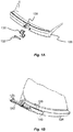
US544336 which is incorporated herein by reference, and will now be briefly described with reference toFigures 1A and 1B . Thefan blade root 126 includes agroove 128 which receives a U-shapedkey member 130. The key member is connected to the blade root using astrap 132 that is connected, e.g. using two pins, to the blade root. A disc for use with the blade ofFigures 1A and 1B includes an axially extending slot for receiving the blade root. A groove is also provided in the disc and circumferentially extends from the slot. The groove is positioned so as to receive thekey member 130 when the blade root is received in the slot of the disc. - A sprung
member 140 and aslider 142 are provided to fix the blade with respect to the disc. To assemble a blade to the disc, thekey member 130 is connected to the blade root. The blade root and key member are then slide into the slot of the disc, so that the key member is axially aligned with the respective grooves of the disc. Thespring member 140 is provided in the slot of the disc, and theslider 142 is moved into the slot so as to cause the spring member to bias the key member into the grooves of the disc. - According to an aspect there is provided a gas turbine engine comprising a disc having a disc slot (e.g. a plurality of disc slots) and a circumferential groove extending from the slot. A blade (e.g. a plurality of blades) having a blade root positioned in the disc slot. The blade root has at least one integrally formed circumferential protrusion that is received in the circumferential groove of the disc.
- The circumferential groove and circumferential protrusion may be considered to be an axial retention arrangement. The circumferential protrusion may be considered to be an integral axial retention member.
- The blade root may comprise two circumferential protrusions and the disc may include two grooves extending from each slot. One protrusion and groove may be on a suction side of the blade and the other protrusion and groove may be on the pressure side of the blade. The two circumferential protrusions may be located in the same chordwise position and the two circumferential grooves may be located in the same chordwise position.
- The or each protrusion may protrude from a flank of the blade root.
- The or each protrusion and groove may be positioned towards one chordal end of the blade.
- The or each protrusion and groove may be positioned towards the leading edge of the blade.
- The or each protrusion may extend in a chordwise direction by approximately 5 to 10% of the length of the blade root.
- The protrusion may have a substantially rectangular cross section with rounded corners.
- The blade may be a fan blade and the disc may be a fan disc.
- According to an aspect there is provided a blade comprising a blade root and a circumferentially extending projection formed integrally with the blade root and extending therefrom.
- The fan blade may be a fan blade of the gas turbine engine according to the previous aspect.
- The skilled person will appreciate that except where mutually exclusive, a feature described in relation to any one of the above aspects may be applied mutatis mutandis to any other aspect. Furthermore except where mutually exclusive any feature described herein may be applied to any aspect and/or combined with any other feature described herein.
- Embodiments will now be described by way of example only, with reference to the Figures, in which:
-
Figure 1A is a perspective exploded view of a fan blade root with a key member; -
Figure 1B is perspective view of a fan blade root and key member ofFigure 1A with a spring member and slider assembly; -
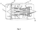
Figure 2 is a sectional side view of a gas turbine engine; -
Figure 3 is a perspective view of a slot in a fan disc; and -
Figure 4 is a perspective view of the root of a fan blade. - With reference to
Figure 1 , a gas turbine engine is generally indicated at 10, having a principal androtational axis 11. Theengine 10 comprises, in axial flow series, anair intake 12, apropulsive fan 13, anintermediate pressure compressor 14, a high-pressure compressor 15, combustion equipment 16, a high-pressure turbine 17, anintermediate pressure turbine 18, a low-pressure turbine 19 and anexhaust nozzle 20. Anacelle 21 generally surrounds theengine 10 and defines both theintake 12 and theexhaust nozzle 20. - The
gas turbine engine 10 works in the conventional manner so that air entering theintake 12 is accelerated by thefan 13 to produce two air flows: a first air flow into theintermediate pressure compressor 14 and a second air flow which passes through abypass duct 22 to provide propulsive thrust. Theintermediate pressure compressor 14 compresses the air flow directed into it before delivering that air to thehigh pressure compressor 15 where further compression takes place. - The compressed air exhausted from the high-
pressure compressor 15 is directed into the combustion equipment 16 where it is mixed with fuel and the mixture combusted. The resultant hot combustion products then expand through, and thereby drive the high, intermediate and low-pressure turbines nozzle 20 to provide additional propulsive thrust. The high 17, intermediate 18 and low 19 pressure turbines drive respectively thehigh pressure compressor 15,intermediate pressure compressor 14 andfan 13, each by suitable interconnecting shaft. - Other gas turbine engines to which the present disclosure may be applied may have alternative configurations. By way of example such engines may have an alternative number of interconnecting shafts (e.g. two) and/or an alternative number of compressors and/or turbines. Further the engine may comprise a gearbox provided in the drive train from a turbine to a compressor and/or fan. The
fan 13 includes a plurality offan blades 24 extending from a disc, which may also be considered to be a hub. - Referring to
Figure 3 , thefan disc 34 includes an axially (or chordwise) extendingslot 36. In the present example, the slot is dovetail shaped, but may be any suitable shape. The disc also includes agroove 38. Thegroove 38 extends circumferentially from and away from theslot 36 of the disc. In the present example the groove is provided proximal to a forward-most position of the fan disc. The groove is substantially rectangular in cross section. - Referring to
Figure 4 , the fan blades include afan blade root 26 that is dove tailed in shape. The shape and size of the fan blade root is complimentary to the shape and size of theslot 36 of thedisc 34. An integral retention feature is provided on the blade root. The retention feature is aprojection 44 that is formed integrally with the fan blade root. The retention feature is provided on aflank 46 of the fan blade root and extends to asection 48 of the blade root that extends in a substantially spanwise (and chordwise) direction. - The
projection 44 is substantially rectangular in cross section and includes rounded edges. The transition between the remainder of the root and the projection may define a curved surface. In this way, there are no sharp corners between the projection and the remainder of the fan blade root. In the present example, the projection extends approximately 5 to 10 % of the chordwise length of the fan blade root. However, the projection may extend any suitable length. - In
Figure 4 , only one projection is shown (i.e. the projection on the pressure side of the blade), but a further projection is provided on the opposite side of the fan blade (i.e. on the suction side of the blade). The projection on the opposite side of the fan blade is provided at the same chordwise position as the projection shown inFigure 4 . Both projections also have the same shape and size. - Referring to
Figures 3 and 4 , thedisc 34 may be formed roughly to shape and size, e.g. by forging, and then disc may be machined to the desired dimensions and to include the desired features. During this machining process theslots 36 and thegrooves 38 can be formed in the disc. The disc can then be post-processed, for example treated for compressive strength using a technique such as deep cold rolling. - The
blade root 26 may be machined from solid, and theprojection 44 may be defined during this machining process. The blade root and projection may then be post-processed to improve compressive strength. For example, the blade root and projection may be deep cold rolled. - In use, the fan blade is assembled in a similar manner to that described in relation to the blade is disc of
US544336 which is incorporated herein by reference, but without the need to assemble a retention arrangement to the fan blade root. Thefan blade root 26 is received in thefan disc slot 36. Theprojections 44 are such that they do not interfere with the sides of the fan disc slot whilst the fan blade root is slid into place in the slot of the disc. A spring member and slider, similar to that shown inUS544336 is then used to bias the fan blade root radially outwardly, such that theprojections 44 are received in therespective grooves 38 of thefan disc 34. - The described axial retention arrangement with a retention member formed integrally with the fan blade root can provide the following advantages:
- The assembly of the gas turbine engine can be simplified because there are fewer parts to assemble, and the risk of the wrong shear key being fitted a fan blade can be mitigated. Fitting the wrong shear key could result in reduced performance in an impact scenario, e.g. bird strike.
- Reduce the number of machining processes required to manufacture the fan blade.
- Simplify the manufacturing process by no longer needing to machine a groove in the blade root to receive a key member.
- Reduce residual stresses in the component.
- Increase the capability of the fan to withstand bird strike and foreign object impact.
- Reduce costs for example by reducing the number of components of the blade and disc arrangement, reducing the amount of material waste when the blade is machined, and allowing lower cost compressive strength processes (such as deep cold rolling) to be used rather than more conventional processes such as shot peening.
- It will be understood that the invention is not limited to the embodiments above-described and various modifications and improvements can be made without departing from the concepts described herein. Except where mutually exclusive, any of the features may be employed separately or in combination with any other features and the disclosure extends to and includes all combinations and subcombinations of one or more features described herein.
- For example, this axial retention arrangement may be used between a disc and blade of a compressor or a turbine.
- The geometry, size and position of the projection on the blade root (and groove of the disc) may be selected to be appropriate for a given application.
- The described blade root is dove tailed in shape, but it may be any other suitable shape, for example fir tree shaped.
Claims (8)
- A gas turbine engine comprising:a disc having a plurality of disc slots and a circumferential groove extending from each slot; anda plurality of blades each having a blade root positioned in one of the plurality of disc slots, each blade root having an integrally formed circumferential protrusion protruding from a flank of the blade root that is received in the respective circumferential groove of the disc.
- The gas turbine engine according to claim 1, wherein the blade root comprises two circumferential protrusions and the disc includes two grooves extending from each slot, wherein one protrusion and groove is on a suction side of the respective blade and the other protrusion and groove is on the pressure side of the respective blade, and wherein the two circumferential protrusions are located in the same chordwise position and the two circumferential grooves are located in the same chordwise position.
- The gas turbine engine according to any one of the previous claims, wherein the protrusion and groove are positioned towards one chordal end of the blade.
- The gas turbine engine according to claim 3, wherein the protrusion and groove are positioned towards the leading edge of the blade.
- The gas turbine engine according to any one of the previous claims, wherein the protrusions extend in a chordwise direction by approximately 5 to 10% of the length of the blade root.
- The gas turbine engine according to any one of the previous claims, wherein the protrusion has a substantially rectangular cross section with rounded corners.
- The gas turbine engine according to any one of the previous claims, wherein the blade is a fan blade and the disc is a fan disc.
- A blade comprising:a blade root; anda circumferentially extending projection formed integrally with the blade root and extending from a flank of the blade root.
Applications Claiming Priority (1)
| Application Number | Priority Date | Filing Date | Title |
|---|---|---|---|
| GR20160100483 | 2016-09-23 |
Publications (1)
| Publication Number | Publication Date |
|---|---|
| EP3299581A1 true EP3299581A1 (en) | 2018-03-28 |
Family
ID=57963615
Family Applications (1)
| Application Number | Title | Priority Date | Filing Date |
|---|---|---|---|
| EP17187010.8A Withdrawn EP3299581A1 (en) | 2016-09-23 | 2017-08-21 | Gas turbine engine |
Country Status (3)
| Country | Link |
|---|---|
| US (1) | US20180087388A1 (en) |
| EP (1) | EP3299581A1 (en) |
| GB (1) | GB201618454D0 (en) |
Families Citing this family (3)
| Publication number | Priority date | Publication date | Assignee | Title |
|---|---|---|---|---|
| US10465537B2 (en) * | 2016-05-27 | 2019-11-05 | General Electric Company | Margin bucket dovetail radial support feature for axial entry buckets |
| GB201704832D0 (en) * | 2017-02-20 | 2017-05-10 | Rolls Royce Plc | Fan |
| US11555407B2 (en) | 2020-05-19 | 2023-01-17 | General Electric Company | Turbomachine rotor assembly |
Citations (5)
| Publication number | Priority date | Publication date | Assignee | Title |
|---|---|---|---|---|
| US544336A (en) | 1895-08-13 | Disintegrator or crusher | ||
| US4527952A (en) * | 1981-06-12 | 1985-07-09 | S.N.E.C.M.A. | Device for locking a turbine rotor blade |
| GB2299834A (en) * | 1995-04-12 | 1996-10-16 | Rolls Royce Plc | Gas turbine engine fan disc |
| US20100290914A1 (en) * | 2009-05-15 | 2010-11-18 | Souers Philip F | Blade Closing Key System for a Turbine Engine |
| EP3006676A1 (en) * | 2014-10-06 | 2016-04-13 | Rolls-Royce plc | Fan for a gas turbine engine, corresponding fan blade and manufacturing method |
-
2016
- 2016-11-02 GB GBGB1618454.1A patent/GB201618454D0/en not_active Ceased
-
2017
- 2017-08-21 EP EP17187010.8A patent/EP3299581A1/en not_active Withdrawn
- 2017-09-08 US US15/699,304 patent/US20180087388A1/en not_active Abandoned
Patent Citations (5)
| Publication number | Priority date | Publication date | Assignee | Title |
|---|---|---|---|---|
| US544336A (en) | 1895-08-13 | Disintegrator or crusher | ||
| US4527952A (en) * | 1981-06-12 | 1985-07-09 | S.N.E.C.M.A. | Device for locking a turbine rotor blade |
| GB2299834A (en) * | 1995-04-12 | 1996-10-16 | Rolls Royce Plc | Gas turbine engine fan disc |
| US20100290914A1 (en) * | 2009-05-15 | 2010-11-18 | Souers Philip F | Blade Closing Key System for a Turbine Engine |
| EP3006676A1 (en) * | 2014-10-06 | 2016-04-13 | Rolls-Royce plc | Fan for a gas turbine engine, corresponding fan blade and manufacturing method |
Also Published As
| Publication number | Publication date |
|---|---|
| US20180087388A1 (en) | 2018-03-29 |
| GB201618454D0 (en) | 2016-12-14 |
Similar Documents
| Publication | Publication Date | Title |
|---|---|---|
| US8336289B2 (en) | Gas turbine engine systems and related methods involving multiple gas turbine cores | |
| US10145250B2 (en) | Chocking and retaining device | |
| EP2971736B1 (en) | Interblade metal platform for ceramic matrix composite turbine blades | |
| EP2971693B1 (en) | Gas turbine engine rotor disk-seal arrangement | |
| EP3225794A1 (en) | Turbine engine shroud assembly | |
| EP3299589B1 (en) | Gas turbine engine | |
| US10767498B2 (en) | Turbine disk with pinned platforms | |
| EP3170988B1 (en) | Rotor for gas turbine engine | |
| EP3299581A1 (en) | Gas turbine engine | |
| US20200011185A1 (en) | Turbine Engine and Method of Assembling | |
| EP3073052B1 (en) | Fan assembly | |
| EP3073054A1 (en) | Chocking and retaining device and rotor assembly | |
| EP3363993B1 (en) | Fan and corresponding gas turbine engine | |
| CN109477435B (en) | Method for improving turbocompressor performance | |
| EP3006676B1 (en) | Fan for a gas turbine engine, corresponding fan blade and manufacturing method | |
| EP3219912A1 (en) | Dual snapped cover plate with retention ring attachment | |
| US9470098B2 (en) | Axial compressor and method for controlling stage-to-stage leakage therein | |
| US20200080431A1 (en) | Turbine wheel assembly with pinned ceramic matrix composite blades | |
| US20220018257A1 (en) | Turbomachine blade having a maximum thickness law with high flutter margin | |
| US10577961B2 (en) | Turbine disk with blade supported platforms | |
| US11686202B1 (en) | Rotor damper with contact biasing feature for turbine engines | |
| US12078069B2 (en) | Rotor with feather seals | |
| EP3219908A1 (en) | Retaining ring groove submerged into a disc hub | |
| GB2556054A (en) | Compressor stage | |
| EP3059389A1 (en) | Gas turbine rotor disc with assymetric circumferential slot |
Legal Events
| Date | Code | Title | Description |
|---|---|---|---|
| PUAI | Public reference made under article 153(3) epc to a published international application that has entered the european phase |
Free format text: ORIGINAL CODE: 0009012 |
|
| STAA | Information on the status of an ep patent application or granted ep patent |
Free format text: STATUS: THE APPLICATION HAS BEEN PUBLISHED |
|
| AK | Designated contracting states |
Kind code of ref document: A1 Designated state(s): AL AT BE BG CH CY CZ DE DK EE ES FI FR GB GR HR HU IE IS IT LI LT LU LV MC MK MT NL NO PL PT RO RS SE SI SK SM TR |
|
| AX | Request for extension of the european patent |
Extension state: BA ME |
|
| STAA | Information on the status of an ep patent application or granted ep patent |
Free format text: STATUS: REQUEST FOR EXAMINATION WAS MADE |
|
| 17P | Request for examination filed |
Effective date: 20180924 |
|
| RBV | Designated contracting states (corrected) |
Designated state(s): AL AT BE BG CH CY CZ DE DK EE ES FI FR GB GR HR HU IE IS IT LI LT LU LV MC MK MT NL NO PL PT RO RS SE SI SK SM TR |
|
| STAA | Information on the status of an ep patent application or granted ep patent |
Free format text: STATUS: EXAMINATION IS IN PROGRESS |
|
| 17Q | First examination report despatched |
Effective date: 20200102 |
|
| RAP1 | Party data changed (applicant data changed or rights of an application transferred) |
Owner name: ROLLS-ROYCE PLC |
|
| STAA | Information on the status of an ep patent application or granted ep patent |
Free format text: STATUS: THE APPLICATION IS DEEMED TO BE WITHDRAWN |
|
| 18D | Application deemed to be withdrawn |
Effective date: 20200603 |