EP3299529B1 - A cutter and method for making dents and fixing insulation - Google Patents
A cutter and method for making dents and fixing insulation Download PDFInfo
- Publication number
- EP3299529B1 EP3299529B1 EP17001556.4A EP17001556A EP3299529B1 EP 3299529 B1 EP3299529 B1 EP 3299529B1 EP 17001556 A EP17001556 A EP 17001556A EP 3299529 B1 EP3299529 B1 EP 3299529B1
- Authority
- EP
- European Patent Office
- Prior art keywords
- insulation
- cutter
- holder
- cutting crown
- plate
- Prior art date
- Legal status (The legal status is an assumption and is not a legal conclusion. Google has not performed a legal analysis and makes no representation as to the accuracy of the status listed.)
- Revoked
Links
Images



Classifications
-
- E—FIXED CONSTRUCTIONS
- E04—BUILDING
- E04B—GENERAL BUILDING CONSTRUCTIONS; WALLS, e.g. PARTITIONS; ROOFS; FLOORS; CEILINGS; INSULATION OR OTHER PROTECTION OF BUILDINGS
- E04B1/00—Constructions in general; Structures which are not restricted either to walls, e.g. partitions, or floors or ceilings or roofs
- E04B1/62—Insulation or other protection; Elements or use of specified material therefor
- E04B1/74—Heat, sound or noise insulation, absorption, or reflection; Other building methods affording favourable thermal or acoustical conditions, e.g. accumulating of heat within walls
- E04B1/76—Heat, sound or noise insulation, absorption, or reflection; Other building methods affording favourable thermal or acoustical conditions, e.g. accumulating of heat within walls specifically with respect to heat only
- E04B1/762—Exterior insulation of exterior walls
- E04B1/7629—Details of the mechanical connection of the insulation to the wall
- E04B1/7633—Dowels with enlarged insulation retaining head
-
- B—PERFORMING OPERATIONS; TRANSPORTING
- B23—MACHINE TOOLS; METAL-WORKING NOT OTHERWISE PROVIDED FOR
- B23B—TURNING; BORING
- B23B51/00—Tools for drilling machines
- B23B51/04—Drills for trepanning
Definitions
- the subject of an invention is a cutter for making dents and fixing insulation with screws especially to exterior walls of buildings.
- Insulation materials for walls of buildings are particularly insulation boards made of rock wool, expanded polystyrene (EPS), wood wool and similar materials. These are materials with a high degree of specific volume and a low degree of a specific mass, fragile and compressible.
- Insulation boards can be fixed to a wall with adhesive, nails or screws. In fixing with screws, a hole has to be drilled into the insulation board and into the wall, a plastic sleeve inserted and a screw screwed. It is advised, that after fixing the insulation board to the wall, the surface of the insulation board is even, without bumps to enable applying of protection and/or aesthetic layer.
- a known solution for fixing insulation boards is among others the solution according to EP 2 752 533 patent.
- a plastic sleeve with a collapsing joint in the area, where the sleeve is in an insulation board is disclosed.
- a cutter grabs a fixing screw and a pressing plate of a plastic sleeve, rotates them and fixates the screw into a plastic sleeve into a wall, that is base material, and a pressing plate cuts into insulation board with its cogs.
- Plastic sleeve in the area of the insulation board collapses and the screw presses the rotating pressing plate into the insulation board.
- Depth is determined with a stopping disc in the shape of a circle; when the stopping disc leans onto the surface of the insulation board, screwing is finished.
- determining depth with the mentioned stopping disc is unpractical, since - which often occurs in construction - when a hole is not precisely right-angled in all directions, a stopping disc can cut into insulation board deeper on one side while on the other side the depth can be insufficient. This causes uneven surfaces on insulation boards, which obstruct the application of protective and/or aesthetic layers.
- the use of a plastic sleeve is also relatively demanding since it has to enable the spinning of the pressing plate and its gliding down a plastic sleeve in the area, where a sleeve is in the insulation board.
- the task and aim of the invention is the construction of such a cutter and consequently, a plastic sleeve, that will overcome the disadvantages of the known solutions and easy determination of the depth of the fixing plate, wherein the depth of the cut into the insulation board will be equal along the entire surface, and simplified installation of the plastic sleeve will be enabled.
- Insulation 9 is usually first ad hoc fixed to a base material 11 with a construction adhesive 10.
- a plastic sleeve 1 is inserted into a hole in a base material 11 through insulation 9.
- a hole has a couple of tenths of a millimetre larger diameter than is the diameter of the lower part of the sleeve 1, i.e. a stem 13.
- a hole in the base material 11 is made by a drill with a diameter equal to a diameter of a hole.
- the plastic sleeve 1 fits the hole made in the base material 11 with its lower part, i.e. with its stem 13. Since the sleeve 1 has in its upper part, i.e.
- the plastic sleeve 1 therefore, consists of the stem 13, i.e. the lower part of the sleeve, and of the upper part, which has a larger diameter.
- a tubular part is formed with a diameter that a screw 2 head can enter into.
- Said tubular part of the sleeve 1 represents approximately one third and the stem 13 approximately two thirds, of the whole length of the sleeve 1.
- the stem 13 has a shrinking area 8.
- the shrinking area 8 is made in one of the known ways, for example, as an "accordion" in a way that when a longitudinal force is applied to the stem 13 the shrinking area 8 collapses, i.e. it shrinks, which results in shortening of the upper part of the stem in a way that the head of the screw 2 presses to the passage formed between the wider and the narrower part of a sleeve 1.
- the plastic sleeve 1 On its upper end, the plastic sleeve 1 has a head in the shape of a plate 15.
- the function of said plate 15 is to enlarge the surface with which the sleeve 1 is pressed to the insulation 9.
- the plate 15 has a hole in a centre of the same diameter as is the diameter of the tubular part of the sleeve 1. Through this hole, a screwdriver extension 14 of the cutter enters and fits into the head of the screw 2, as shown in fig. 2 .
- the cutter is fixed to a screwing pole 6.
- the screwing pole 6 has shallow holes along its surface, i.e. adjustment holes 7, which enable the positioning of the cutter along the screwing pole 6 and by that the adjustment of the depth, to which the screwdriver extension 14 can reach.
- the adjustment of the depth i.e. the positioning of the cutter, is done by a fixing screw 5 which is positioned in a holder 3 of a cutting crown 4.
- the cutting crown 4 is centrally fixed to the holder 3.
- the cutting crown 4 has from 2 to 5 percent larger diameter than the holder 3, preferably 3 percent. This enables undisturbed penetration of the holder 3 in the cut surface of insulation 9.
- the cutting crown 4 has from 5 to 15 percent larger diameter than is the diameter of the plate 15, preferably 13 percent. In this way, the surface of the plate 15 does not obstruct the cutting of the cutting crown 4 in insulation 9.
- the cutting crown 4 is cylindrical, open at the bottom and with at least one deformation 16 in the lower rim, functioning as a tooth for insulation cutting.
- the holder 3 serves also to visually determine the depth of screwing and penetration of the plate 15 into the insulation 9.
- the cutter is removed and in a hole, made by the cutting crown 4 and plate 15, a cap 12 is inserted.
- the cap 12 is made from equal or similar materials as insulation 9 and provides a flat surface of the insulation at the point of attachment of the insulation 9 to the base material 11.
Landscapes
- Engineering & Computer Science (AREA)
- Physics & Mathematics (AREA)
- Architecture (AREA)
- Mechanical Engineering (AREA)
- Acoustics & Sound (AREA)
- Electromagnetism (AREA)
- Civil Engineering (AREA)
- Structural Engineering (AREA)
- Bolts, Nuts, And Washers (AREA)
- Connection Of Plates (AREA)
Description
- The subject of an invention is a cutter for making dents and fixing insulation with screws especially to exterior walls of buildings. Insulation materials for walls of buildings are particularly insulation boards made of rock wool, expanded polystyrene (EPS), wood wool and similar materials. These are materials with a high degree of specific volume and a low degree of a specific mass, fragile and compressible. Insulation boards can be fixed to a wall with adhesive, nails or screws. In fixing with screws, a hole has to be drilled into the insulation board and into the wall, a plastic sleeve inserted and a screw screwed. It is advised, that after fixing the insulation board to the wall, the surface of the insulation board is even, without bumps to enable applying of protection and/or aesthetic layer.
- A known solution for fixing insulation boards is among others the solution according to
EP 2 752 533 - Another solution for fixing insulation is known from
document DE 10 2004 006 936 A1 . This document discloses the features of the preamble ofclaim 1. - The task and aim of the invention is the construction of such a cutter and consequently, a plastic sleeve, that will overcome the disadvantages of the known solutions and easy determination of the depth of the fixing plate, wherein the depth of the cut into the insulation board will be equal along the entire surface, and simplified installation of the plastic sleeve will be enabled.
- According to the invention, the task has been solved by independent patent claims.
- The invention will be described with the help of the following figures:
-
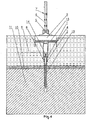
Fig. 1 : a plastic sleeve inserted into a hole; cutter in an approaching position, -
Fig. 2 : a cutter in a position when a screwing pole fits into a screw head, -
Fig. 3 : a cutting crown of the cutter cuts into an insulation board, -
Fig. 4 : a cutter finishes screwing and presses a fixing plate to defined depth, -
Fig. 5 : screwing of an insulation board to the base material is finished. -
Insulation 9 is usually first ad hoc fixed to abase material 11 with a construction adhesive 10. As shown infig. 1 , aplastic sleeve 1 is inserted into a hole in abase material 11 throughinsulation 9. A hole has a couple of tenths of a millimetre larger diameter than is the diameter of the lower part of thesleeve 1, i.e. astem 13. A hole in thebase material 11 is made by a drill with a diameter equal to a diameter of a hole. Theplastic sleeve 1 fits the hole made in thebase material 11 with its lower part, i.e. with itsstem 13. Since thesleeve 1 has in its upper part, i.e. part which is plunged only ininsulation 9, a larger diameter than in itsstem 13, the sleeve presses into thecompressible insulation 9 which deforms accordingly. Theplastic sleeve 1, therefore, consists of thestem 13, i.e. the lower part of the sleeve, and of the upper part, which has a larger diameter. In the upper part of the sleeve 1 a tubular part is formed with a diameter that ascrew 2 head can enter into. Said tubular part of thesleeve 1 represents approximately one third and thestem 13 approximately two thirds, of the whole length of thesleeve 1. In the upper part of thestem 13, that is, in the part where thestem 13 is plunged ininsulation 9, thestem 13 has ashrinking area 8. Theshrinking area 8 is made in one of the known ways, for example, as an "accordion" in a way that when a longitudinal force is applied to thestem 13 theshrinking area 8 collapses, i.e. it shrinks, which results in shortening of the upper part of the stem in a way that the head of thescrew 2 presses to the passage formed between the wider and the narrower part of asleeve 1. On its upper end, theplastic sleeve 1 has a head in the shape of aplate 15. The function ofsaid plate 15 is to enlarge the surface with which thesleeve 1 is pressed to theinsulation 9. Theplate 15 has a hole in a centre of the same diameter as is the diameter of the tubular part of thesleeve 1. Through this hole, ascrewdriver extension 14 of the cutter enters and fits into the head of thescrew 2, as shown infig. 2 . - The cutter is fixed to a
screwing pole 6. Thescrewing pole 6 has shallow holes along its surface, i.e.adjustment holes 7, which enable the positioning of the cutter along thescrewing pole 6 and by that the adjustment of the depth, to which thescrewdriver extension 14 can reach. The adjustment of the depth, i.e. the positioning of the cutter, is done by afixing screw 5 which is positioned in aholder 3 of a cutting crown 4. The cutting crown 4 is centrally fixed to theholder 3. The cutting crown 4 has from 2 to 5 percent larger diameter than theholder 3, preferably 3 percent. This enables undisturbed penetration of theholder 3 in the cut surface ofinsulation 9. Equally, the cutting crown 4 has from 5 to 15 percent larger diameter than is the diameter of theplate 15, preferably 13 percent. In this way, the surface of theplate 15 does not obstruct the cutting of the cutting crown 4 ininsulation 9. - The cutting crown 4 is cylindrical, open at the bottom and with at least one
deformation 16 in the lower rim, functioning as a tooth for insulation cutting. When thescrewing pole 6 together with theholder 3, the cutting crown 4 and thescrewdriver extension 14 spins, then at the same time as thescrew 2 is screwed into thestem 13 by thescrewdriver extension 14, the cutting crown 4 cuts intoinsulation 9 as is shown infig. 3 . With further spinning and cutting theplate 15 plunges into theinsulation 9 along the insulation wall cut by the cutting crown 4. By its plunging theplate 15 compresses theinsulation 9 below it; thescrew 2 in theshrinking area 8 shrinks and thus shortens thestem 13 of thesleeve 1. Screwing continues until the upper surface of theholder 3 of the cutting crown 4 levels with theinsulation surface 9. Thus theholder 3 serves also to visually determine the depth of screwing and penetration of theplate 15 into theinsulation 9. The height of theholder 3, i.e. the position of theholder 3 along thescrewing pole 6, therefore determines the depth of the hole for theplate 15, i.e. the height of theholder 3 is equal to the depth of the hole for theplate 15. After the screwing is finished, the cutter is removed and in a hole, made by the cutting crown 4 andplate 15, acap 12 is inserted. Thecap 12 is made from equal or similar materials asinsulation 9 and provides a flat surface of the insulation at the point of attachment of theinsulation 9 to thebase material 11.
Claims (2)
- A cutter for making dents and fixing insulation (9) with screws to the exterior walls of the buildings and said insulation are predominantly insulation boards made of rock wool, expanded polystyrene (EPS), wood wool and similar, whereby said insulation is fixed to the base material (11) with screws (2), screwed in plastic sleeves (1) with plates (15), inserted in holes made in the base material and insulation,
characterized in that,
said cutter consists of a screwing pole (6) with adjustment holes (7), a holder (3) of a cutting crown (4) with a fixing screw (5), said cutting crown (4) is centrally fixed to the lower part of the holder (3), said cutting crown (4) is cylindrical, open at the bottom and with at least one deformation (16) in the lower rim, functioning as a tooth for insulation (9) cutting, said cutting crown (4) enabling the plate (15) of said plastic sleeve to plunge into the insulation (9) by pressing, and whereby the diameter of the cutting crown (4) is from 2 to 5 percent larger than the diameter of the holder (3) and from 5 to 15 percent larger than the diameter of the plate (15) of the plastic sleeve, and on the screwing pole (6) under the cutting crown (4) a screwdriver extension (14) of the cutter is fixed, whereby the screwing pole (6) has shallow holes along its surface, i being said adjustment holes (7), which enable the positioning of the cutter along the screwing pole (6) and by that the adjustment of the depth, to which the screwdriver extension (14) can reach and whereby the height of the holder (3), i.e. the positioning of the holder (3) along the screwing pole (6) determines the depth of a hole for a plate (15). - A process for fixing insulation to the base material with a cutter according to claim 1, whereby the insulation is fixed to the base material with screws, screwed into plastic sleeves with plates, inserted in holes made in the base material and insulation,
characterized in that,
into a hole in a base material (11) a plastic sleeve (1) with a plate (15) and a shrinking area (8) is inserted and a screw (2) is inserted into the sleeve (1); the holder (3) of the cutting crown (4) is fixed with the fixing screw (5) into the selected adjustment hole (7) to adjust the depth, to which the screwdriver extension (14) will reach, a the screwdriver extension (14) of the cutter fits into a head of the screw (2); when the screwdriver extension (14) is screwing the screw (2) into a stem (13), a cutting crown (4) simultaneously cuts into insulation (9); when cutting, the plate (15) of the plastic sleeve is plunging into insulation (9) along the insulation wall cut by the cutting crown (4) by pressing, whereby by its plunging, the plate (15) compresses the insulation (9) below; the screw (2) in the shrinking area (8) shrinks and thus shortens the stem (13) of the sleeve (1); screwing continues until the upper surface of the holder (3) of the cutting crown (4) levels with the insulation (9) surface.
Priority Applications (1)
| Application Number | Priority Date | Filing Date | Title |
|---|---|---|---|
| SI201730593T SI3299529T1 (en) | 2016-09-23 | 2017-09-19 | A cutter and method for making dents and fixing insulation |
Applications Claiming Priority (1)
| Application Number | Priority Date | Filing Date | Title |
|---|---|---|---|
| SI201600238A SI25301A2 (en) | 2016-09-23 | 2016-09-23 | The milling cutter for making cavities and mounting insulation |
Publications (2)
| Publication Number | Publication Date |
|---|---|
| EP3299529A1 EP3299529A1 (en) | 2018-03-28 |
| EP3299529B1 true EP3299529B1 (en) | 2020-11-04 |
Family
ID=60957005
Family Applications (1)
| Application Number | Title | Priority Date | Filing Date |
|---|---|---|---|
| EP17001556.4A Revoked EP3299529B1 (en) | 2016-09-23 | 2017-09-19 | A cutter and method for making dents and fixing insulation |
Country Status (2)
| Country | Link |
|---|---|
| EP (1) | EP3299529B1 (en) |
| SI (2) | SI25301A2 (en) |
Families Citing this family (2)
| Publication number | Priority date | Publication date | Assignee | Title |
|---|---|---|---|---|
| CN111663677A (en) * | 2020-06-10 | 2020-09-15 | 夏凯敏 | Light heat-insulating wall for assembled building outer wall |
| US20230287678A1 (en) * | 2022-03-11 | 2023-09-14 | Certainteed Llc | Insulation standoffs and exterior insulation systems |
Family Cites Families (3)
| Publication number | Priority date | Publication date | Assignee | Title |
|---|---|---|---|---|
| SI2752533T1 (en) | 2001-12-05 | 2015-11-30 | Ejot Gmbh & Co.Kg | Device for driving an expansion element into a dowel. |
| DE102004006936A1 (en) * | 2004-02-12 | 2005-09-01 | Friedr. Trurnit Gmbh | Method for securing insulation panels using a special tool with fitted hole saw and central driving bit for a recessed fitting of the fasteners into the panels |
| EP2977135B1 (en) * | 2014-07-23 | 2018-04-18 | EJOT Baubefestigungen GmbH | Device and method for creating a recess in insulating materials |
-
2016
- 2016-09-23 SI SI201600238A patent/SI25301A2/en active IP Right Grant
-
2017
- 2017-09-19 EP EP17001556.4A patent/EP3299529B1/en not_active Revoked
- 2017-09-19 SI SI201730593T patent/SI3299529T1/en unknown
Non-Patent Citations (3)
| Title |
|---|
| "PREISKATALOG / PRODUKTÜBERSICHT", SYNTHESA, 2015, pages 1 - 500 |
| MARTIN HOHGARDT: "ANCHOR WITH A SCREW {PPV)", LESKOVEC, 9 June 2016 (2016-06-09), XP055920435, Retrieved from the Internet <URL:http://www.leskovec.si/en/ANCHOR-WITH-A-SCREW-PPV/> [retrieved on 20220512] |
| TECHNICAL SPECIFICATION OF CAPATECT SCHRAUBDÜBEL 3D |
Also Published As
| Publication number | Publication date |
|---|---|
| SI3299529T1 (en) | 2021-02-26 |
| SI25301A2 (en) | 2018-04-30 |
| EP3299529A1 (en) | 2018-03-28 |
Similar Documents
| Publication | Publication Date | Title |
|---|---|---|
| DK2840201T3 (en) | Dowel and method for deep mounting of such in insulating material plates | |
| EP2505288B1 (en) | A drill bit and single piece screw combination and a method for hanging a fascia board on a joist | |
| JPH048645B2 (en) | ||
| JP2021517868A (en) | Long hole saw for composite insulation panels | |
| EP3299529A1 (en) | A cutter and method for making dents and fixing insulation | |
| RU2474734C9 (en) | Self-drilling screw | |
| KR100900886B1 (en) | Insulation fixtures for aluminum formwork | |
| AU2022203197A1 (en) | Fastening method | |
| JP2020033698A (en) | Post-installation anchor and its installation method | |
| CN104583504A (en) | Fixing the insulator to the wall unit | |
| KR100981679B1 (en) | Perforation Device | |
| EP2957686B1 (en) | Jig for setting an oblong expansion element in a dowel | |
| EP0429449A1 (en) | Fixing system | |
| CN103938829B (en) | Surface of decorative plate holeless installation method | |
| KR20130086488A (en) | Countersunk screw | |
| KR100991826B1 (en) | Drill Bits | |
| JP2016113762A (en) | Anchor installed after concrete curing, installation method for anchor installed after concrete curing, and system for anchor installed after concrete curing | |
| EP4426954B1 (en) | Screw, its use and a method for fastening workpieces and decking a terrace | |
| JP3094372U (en) | Drill | |
| JP2001280318A (en) | Nail | |
| JP4199909B2 (en) | Screw fastener | |
| GB2540803A (en) | Drill bit cooling device | |
| PL67062Y1 (en) | SDS-PLUS extension | |
| JP3144155U (en) | Microvibration diamond core drill | |
| KR101469074B1 (en) | Insert of indexable drill |
Legal Events
| Date | Code | Title | Description |
|---|---|---|---|
| PUAI | Public reference made under article 153(3) epc to a published international application that has entered the european phase |
Free format text: ORIGINAL CODE: 0009012 |
|
| STAA | Information on the status of an ep patent application or granted ep patent |
Free format text: STATUS: THE APPLICATION HAS BEEN PUBLISHED |
|
| AK | Designated contracting states |
Kind code of ref document: A1 Designated state(s): AL AT BE BG CH CY CZ DE DK EE ES FI FR GB GR HR HU IE IS IT LI LT LU LV MC MK MT NL NO PL PT RO RS SE SI SK SM TR |
|
| AX | Request for extension of the european patent |
Extension state: BA ME |
|
| STAA | Information on the status of an ep patent application or granted ep patent |
Free format text: STATUS: REQUEST FOR EXAMINATION WAS MADE |
|
| 17P | Request for examination filed |
Effective date: 20180821 |
|
| RAX | Requested extension states of the european patent have changed |
Extension state: ME Payment date: 20180821 Extension state: BA Payment date: 20180821 |
|
| RBV | Designated contracting states (corrected) |
Designated state(s): AL AT BE BG CH CY CZ DE DK EE ES FI FR GB GR HR HU IE IS IT LI LT LU LV MC MK MT NL NO PL PT RO RS SE SI SK SM TR |
|
| GRAP | Despatch of communication of intention to grant a patent |
Free format text: ORIGINAL CODE: EPIDOSNIGR1 |
|
| STAA | Information on the status of an ep patent application or granted ep patent |
Free format text: STATUS: GRANT OF PATENT IS INTENDED |
|
| INTG | Intention to grant announced |
Effective date: 20200629 |
|
| GRAS | Grant fee paid |
Free format text: ORIGINAL CODE: EPIDOSNIGR3 |
|
| GRAA | (expected) grant |
Free format text: ORIGINAL CODE: 0009210 |
|
| STAA | Information on the status of an ep patent application or granted ep patent |
Free format text: STATUS: THE PATENT HAS BEEN GRANTED |
|
| AK | Designated contracting states |
Kind code of ref document: B1 Designated state(s): AL AT BE BG CH CY CZ DE DK EE ES FI FR GB GR HR HU IE IS IT LI LT LU LV MC MK MT NL NO PL PT RO RS SE SI SK SM TR |
|
| AX | Request for extension of the european patent |
Extension state: BA ME |
|
| REG | Reference to a national code |
Ref country code: GB Ref legal event code: FG4D |
|
| REG | Reference to a national code |
Ref country code: CH Ref legal event code: EP |
|
| REG | Reference to a national code |
Ref country code: AT Ref legal event code: REF Ref document number: 1330995 Country of ref document: AT Kind code of ref document: T Effective date: 20201115 |
|
| REG | Reference to a national code |
Ref country code: IE Ref legal event code: FG4D |
|
| REG | Reference to a national code |
Ref country code: DE Ref legal event code: R096 Ref document number: 602017026603 Country of ref document: DE |
|
| REG | Reference to a national code |
Ref country code: NL Ref legal event code: MP Effective date: 20201104 |
|
| REG | Reference to a national code |
Ref country code: AT Ref legal event code: MK05 Ref document number: 1330995 Country of ref document: AT Kind code of ref document: T Effective date: 20201104 |
|
| PG25 | Lapsed in a contracting state [announced via postgrant information from national office to epo] |
Ref country code: FI Free format text: LAPSE BECAUSE OF FAILURE TO SUBMIT A TRANSLATION OF THE DESCRIPTION OR TO PAY THE FEE WITHIN THE PRESCRIBED TIME-LIMIT Effective date: 20201104 Ref country code: GR Free format text: LAPSE BECAUSE OF FAILURE TO SUBMIT A TRANSLATION OF THE DESCRIPTION OR TO PAY THE FEE WITHIN THE PRESCRIBED TIME-LIMIT Effective date: 20210205 Ref country code: RS Free format text: LAPSE BECAUSE OF FAILURE TO SUBMIT A TRANSLATION OF THE DESCRIPTION OR TO PAY THE FEE WITHIN THE PRESCRIBED TIME-LIMIT Effective date: 20201104 Ref country code: PT Free format text: LAPSE BECAUSE OF FAILURE TO SUBMIT A TRANSLATION OF THE DESCRIPTION OR TO PAY THE FEE WITHIN THE PRESCRIBED TIME-LIMIT Effective date: 20210304 Ref country code: NO Free format text: LAPSE BECAUSE OF FAILURE TO SUBMIT A TRANSLATION OF THE DESCRIPTION OR TO PAY THE FEE WITHIN THE PRESCRIBED TIME-LIMIT Effective date: 20210204 |
|
| PG25 | Lapsed in a contracting state [announced via postgrant information from national office to epo] |
Ref country code: SE Free format text: LAPSE BECAUSE OF FAILURE TO SUBMIT A TRANSLATION OF THE DESCRIPTION OR TO PAY THE FEE WITHIN THE PRESCRIBED TIME-LIMIT Effective date: 20201104 Ref country code: PL Free format text: LAPSE BECAUSE OF FAILURE TO SUBMIT A TRANSLATION OF THE DESCRIPTION OR TO PAY THE FEE WITHIN THE PRESCRIBED TIME-LIMIT Effective date: 20201104 Ref country code: LV Free format text: LAPSE BECAUSE OF FAILURE TO SUBMIT A TRANSLATION OF THE DESCRIPTION OR TO PAY THE FEE WITHIN THE PRESCRIBED TIME-LIMIT Effective date: 20201104 Ref country code: IS Free format text: LAPSE BECAUSE OF FAILURE TO SUBMIT A TRANSLATION OF THE DESCRIPTION OR TO PAY THE FEE WITHIN THE PRESCRIBED TIME-LIMIT Effective date: 20210304 Ref country code: BG Free format text: LAPSE BECAUSE OF FAILURE TO SUBMIT A TRANSLATION OF THE DESCRIPTION OR TO PAY THE FEE WITHIN THE PRESCRIBED TIME-LIMIT Effective date: 20210204 Ref country code: ES Free format text: LAPSE BECAUSE OF FAILURE TO SUBMIT A TRANSLATION OF THE DESCRIPTION OR TO PAY THE FEE WITHIN THE PRESCRIBED TIME-LIMIT Effective date: 20201104 Ref country code: AT Free format text: LAPSE BECAUSE OF FAILURE TO SUBMIT A TRANSLATION OF THE DESCRIPTION OR TO PAY THE FEE WITHIN THE PRESCRIBED TIME-LIMIT Effective date: 20201104 |
|
| REG | Reference to a national code |
Ref country code: LT Ref legal event code: MG9D |
|
| PG25 | Lapsed in a contracting state [announced via postgrant information from national office to epo] |
Ref country code: HR Free format text: LAPSE BECAUSE OF FAILURE TO SUBMIT A TRANSLATION OF THE DESCRIPTION OR TO PAY THE FEE WITHIN THE PRESCRIBED TIME-LIMIT Effective date: 20201104 |
|
| PG25 | Lapsed in a contracting state [announced via postgrant information from national office to epo] |
Ref country code: LT Free format text: LAPSE BECAUSE OF FAILURE TO SUBMIT A TRANSLATION OF THE DESCRIPTION OR TO PAY THE FEE WITHIN THE PRESCRIBED TIME-LIMIT Effective date: 20201104 Ref country code: SM Free format text: LAPSE BECAUSE OF FAILURE TO SUBMIT A TRANSLATION OF THE DESCRIPTION OR TO PAY THE FEE WITHIN THE PRESCRIBED TIME-LIMIT Effective date: 20201104 Ref country code: EE Free format text: LAPSE BECAUSE OF FAILURE TO SUBMIT A TRANSLATION OF THE DESCRIPTION OR TO PAY THE FEE WITHIN THE PRESCRIBED TIME-LIMIT Effective date: 20201104 Ref country code: CZ Free format text: LAPSE BECAUSE OF FAILURE TO SUBMIT A TRANSLATION OF THE DESCRIPTION OR TO PAY THE FEE WITHIN THE PRESCRIBED TIME-LIMIT Effective date: 20201104 Ref country code: SK Free format text: LAPSE BECAUSE OF FAILURE TO SUBMIT A TRANSLATION OF THE DESCRIPTION OR TO PAY THE FEE WITHIN THE PRESCRIBED TIME-LIMIT Effective date: 20201104 Ref country code: RO Free format text: LAPSE BECAUSE OF FAILURE TO SUBMIT A TRANSLATION OF THE DESCRIPTION OR TO PAY THE FEE WITHIN THE PRESCRIBED TIME-LIMIT Effective date: 20201104 |
|
| REG | Reference to a national code |
Ref country code: DE Ref legal event code: R026 Ref document number: 602017026603 Country of ref document: DE |
|
| PLBI | Opposition filed |
Free format text: ORIGINAL CODE: 0009260 |
|
| PLAX | Notice of opposition and request to file observation + time limit sent |
Free format text: ORIGINAL CODE: EPIDOSNOBS2 |
|
| PG25 | Lapsed in a contracting state [announced via postgrant information from national office to epo] |
Ref country code: DK Free format text: LAPSE BECAUSE OF FAILURE TO SUBMIT A TRANSLATION OF THE DESCRIPTION OR TO PAY THE FEE WITHIN THE PRESCRIBED TIME-LIMIT Effective date: 20201104 |
|
| 26 | Opposition filed |
Opponent name: EJOT BAUBEFESTIGUNGEN GMBH Effective date: 20210803 |
|
| PG25 | Lapsed in a contracting state [announced via postgrant information from national office to epo] |
Ref country code: IT Free format text: LAPSE BECAUSE OF FAILURE TO SUBMIT A TRANSLATION OF THE DESCRIPTION OR TO PAY THE FEE WITHIN THE PRESCRIBED TIME-LIMIT Effective date: 20201104 Ref country code: NL Free format text: LAPSE BECAUSE OF FAILURE TO SUBMIT A TRANSLATION OF THE DESCRIPTION OR TO PAY THE FEE WITHIN THE PRESCRIBED TIME-LIMIT Effective date: 20201104 Ref country code: AL Free format text: LAPSE BECAUSE OF FAILURE TO SUBMIT A TRANSLATION OF THE DESCRIPTION OR TO PAY THE FEE WITHIN THE PRESCRIBED TIME-LIMIT Effective date: 20201104 |
|
| PGFP | Annual fee paid to national office [announced via postgrant information from national office to epo] |
Ref country code: FR Payment date: 20210920 Year of fee payment: 5 Ref country code: IE Payment date: 20210917 Year of fee payment: 5 Ref country code: MC Payment date: 20210920 Year of fee payment: 5 Ref country code: LU Payment date: 20210917 Year of fee payment: 5 Ref country code: CH Payment date: 20210921 Year of fee payment: 5 |
|
| PGFP | Annual fee paid to national office [announced via postgrant information from national office to epo] |
Ref country code: BE Payment date: 20210917 Year of fee payment: 5 Ref country code: GB Payment date: 20210920 Year of fee payment: 5 Ref country code: SI Payment date: 20210818 Year of fee payment: 5 Ref country code: DE Payment date: 20210917 Year of fee payment: 5 |
|
| PLBB | Reply of patent proprietor to notice(s) of opposition received |
Free format text: ORIGINAL CODE: EPIDOSNOBS3 |
|
| PLAB | Opposition data, opponent's data or that of the opponent's representative modified |
Free format text: ORIGINAL CODE: 0009299OPPO |
|
| R26 | Opposition filed (corrected) |
Opponent name: EJOT SE & CO. KG Effective date: 20210803 |
|
| REG | Reference to a national code |
Ref country code: DE Ref legal event code: R103 Ref document number: 602017026603 Country of ref document: DE Ref country code: DE Ref legal event code: R064 Ref document number: 602017026603 Country of ref document: DE |
|
| RDAF | Communication despatched that patent is revoked |
Free format text: ORIGINAL CODE: EPIDOSNREV1 |
|
| RDAG | Patent revoked |
Free format text: ORIGINAL CODE: 0009271 |
|
| STAA | Information on the status of an ep patent application or granted ep patent |
Free format text: STATUS: PATENT REVOKED |
|
| REG | Reference to a national code |
Ref country code: CH Ref legal event code: PL |
|
| 27W | Patent revoked |
Effective date: 20221104 |
|
| GBPR | Gb: patent revoked under art. 102 of the ep convention designating the uk as contracting state |
Effective date: 20221104 |
|
| PG25 | Lapsed in a contracting state [announced via postgrant information from national office to epo] |
Ref country code: CY Free format text: LAPSE BECAUSE OF FAILURE TO SUBMIT A TRANSLATION OF THE DESCRIPTION OR TO PAY THE FEE WITHIN THE PRESCRIBED TIME-LIMIT Effective date: 20201104 |
|
| REG | Reference to a national code |
Ref country code: SI Ref legal event code: KO00 Effective date: 20230517 |
|
| PG25 | Lapsed in a contracting state [announced via postgrant information from national office to epo] |
Ref country code: SI Free format text: LAPSE BECAUSE OF NON-PAYMENT OF DUE FEES Effective date: 20220920 |
|
| PG25 | Lapsed in a contracting state [announced via postgrant information from national office to epo] |
Ref country code: HU Free format text: LAPSE BECAUSE OF FAILURE TO SUBMIT A TRANSLATION OF THE DESCRIPTION OR TO PAY THE FEE WITHIN THE PRESCRIBED TIME-LIMIT; INVALID AB INITIO Effective date: 20170919 |
|
| PG25 | Lapsed in a contracting state [announced via postgrant information from national office to epo] |
Ref country code: MK Free format text: LAPSE BECAUSE OF FAILURE TO SUBMIT A TRANSLATION OF THE DESCRIPTION OR TO PAY THE FEE WITHIN THE PRESCRIBED TIME-LIMIT Effective date: 20201104 |
|
| PG25 | Lapsed in a contracting state [announced via postgrant information from national office to epo] |
Ref country code: LU Free format text: LAPSE BECAUSE OF NON-PAYMENT OF DUE FEES Effective date: 20220930 |
|
| PG25 | Lapsed in a contracting state [announced via postgrant information from national office to epo] |
Ref country code: IE Free format text: LAPSE BECAUSE OF NON-PAYMENT OF DUE FEES Effective date: 20220323 |
|
| PG25 | Lapsed in a contracting state [announced via postgrant information from national office to epo] |
Ref country code: LU Free format text: LAPSE BECAUSE OF NON-PAYMENT OF DUE FEES Effective date: 20220930 Ref country code: IE Free format text: LAPSE BECAUSE OF NON-PAYMENT OF DUE FEES Effective date: 20220323 |
|
| PG25 | Lapsed in a contracting state [announced via postgrant information from national office to epo] |
Ref country code: MT Free format text: LAPSE BECAUSE OF FAILURE TO SUBMIT A TRANSLATION OF THE DESCRIPTION OR TO PAY THE FEE WITHIN THE PRESCRIBED TIME-LIMIT Effective date: 20201104 |
|
| PG25 | Lapsed in a contracting state [announced via postgrant information from national office to epo] |
Ref country code: MC Free format text: LAPSE BECAUSE OF NON-PAYMENT OF DUE FEES Effective date: 20220930 |
|
| PG25 | Lapsed in a contracting state [announced via postgrant information from national office to epo] |
Ref country code: MC Free format text: LAPSE BECAUSE OF NON-PAYMENT OF DUE FEES Effective date: 20220930 |
|
| PG25 | Lapsed in a contracting state [announced via postgrant information from national office to epo] |
Ref country code: FR Free format text: LAPSE BECAUSE OF NON-PAYMENT OF DUE FEES Effective date: 20220930 |
|
| PG25 | Lapsed in a contracting state [announced via postgrant information from national office to epo] |
Ref country code: BE Free format text: LAPSE BECAUSE OF NON-PAYMENT OF DUE FEES Effective date: 20220930 |
|
| PG25 | Lapsed in a contracting state [announced via postgrant information from national office to epo] |
Ref country code: GB Free format text: LAPSE BECAUSE OF NON-PAYMENT OF DUE FEES Effective date: 20220919 |
|
| PG25 | Lapsed in a contracting state [announced via postgrant information from national office to epo] |
Ref country code: TR Free format text: LAPSE BECAUSE OF FAILURE TO SUBMIT A TRANSLATION OF THE DESCRIPTION OR TO PAY THE FEE WITHIN THE PRESCRIBED TIME-LIMIT Effective date: 20201104 |