EP3299510A1 - Open lid/closed lid structure of washing machine and washing machine - Google Patents
Open lid/closed lid structure of washing machine and washing machine Download PDFInfo
- Publication number
- EP3299510A1 EP3299510A1 EP16799153.8A EP16799153A EP3299510A1 EP 3299510 A1 EP3299510 A1 EP 3299510A1 EP 16799153 A EP16799153 A EP 16799153A EP 3299510 A1 EP3299510 A1 EP 3299510A1
- Authority
- EP
- European Patent Office
- Prior art keywords
- cover
- washing machine
- slide groove
- elastic support
- seat
- Prior art date
- Legal status (The legal status is an assumption and is not a legal conclusion. Google has not performed a legal analysis and makes no representation as to the accuracy of the status listed.)
- Withdrawn
Links
Images


Classifications
-
- D—TEXTILES; PAPER
- D06—TREATMENT OF TEXTILES OR THE LIKE; LAUNDERING; FLEXIBLE MATERIALS NOT OTHERWISE PROVIDED FOR
- D06F—LAUNDERING, DRYING, IRONING, PRESSING OR FOLDING TEXTILE ARTICLES
- D06F39/00—Details of washing machines not specific to a single type of machines covered by groups D06F9/00 - D06F27/00
- D06F39/12—Casings; Tubs
- D06F39/14—Doors or covers; Securing means therefor
-
- D—TEXTILES; PAPER
- D06—TREATMENT OF TEXTILES OR THE LIKE; LAUNDERING; FLEXIBLE MATERIALS NOT OTHERWISE PROVIDED FOR
- D06F—LAUNDERING, DRYING, IRONING, PRESSING OR FOLDING TEXTILE ARTICLES
- D06F37/00—Details specific to washing machines covered by groups D06F21/00 - D06F25/00
- D06F37/26—Casings; Tubs
- D06F37/28—Doors; Security means therefor
-
- E—FIXED CONSTRUCTIONS
- E05—LOCKS; KEYS; WINDOW OR DOOR FITTINGS; SAFES
- E05Y—INDEXING SCHEME ASSOCIATED WITH SUBCLASSES E05D AND E05F, RELATING TO CONSTRUCTION ELEMENTS, ELECTRIC CONTROL, POWER SUPPLY, POWER SIGNAL OR TRANSMISSION, USER INTERFACES, MOUNTING OR COUPLING, DETAILS, ACCESSORIES, AUXILIARY OPERATIONS NOT OTHERWISE PROVIDED FOR, APPLICATION THEREOF
- E05Y2900/00—Application of doors, windows, wings or fittings thereof
- E05Y2900/30—Application of doors, windows, wings or fittings thereof for domestic appliances
- E05Y2900/312—Application of doors, windows, wings or fittings thereof for domestic appliances for washing machines or laundry dryers
Definitions
- the present disclosure relates to the field of washing machines, and in particular relates to an opening and closing lid structure of a washing machine and a washing machine.
- Chinese patent with application No. CN200910118744.2 provides a washing machine lid structure, which does not generate a striking noise during opening and closing and allows smooth opening and closing operation on the washing machine lid.
- the structure includes: a lid capable of being opened and closed freely which is arranged above a top cap located at an upper part of a washing machine body; a toggle spring which allows switching of an applied force between an opening or closing direction of the lid; and a rotary buffer damper capable of attenuating rotation of the lid.
- the buffer damper is arranged in a damper holder in a freely rotating and sliding manner, with a free rotation range at a specified angle provided in a rotating direction between the damper holder and the buffer damper.
- the attenuation force of the buffer damper has no effect on the rotation of the lid due to the presence of the free rotation range. So at the initial stage of the opening operation and the closing operating of the lid, a user only needs to perform a force capable of resisting the load of the toggle spring to perform the opening and closing operation on the lid, which is very convenient for the opening and closing operation. However, it cannot solve the problem that the lid is very likely to be automatically closed after being opened.
- An object of the present disclosure is to overcome the shortcomings of the prior art, and provide an opening and closing lid structure of a washing machine and a washing machine.
- an opening and closing lid structure of a washing machine including a cover, a seat and a control device, a turning shaft of the cover being mounted to the seat.
- the control device includes a slide groove and an elastic support; the slide groove is arranged on the turning shaft of the cover along a rotating direction; a lower end of the elastic support is mounted to the seat, and an upper end of the elastic support is slidably supported in the slide groove; and the slide groove is provided with a restraint slot therein, into which the elastic support slides to prevent the cover from automatic closure after being opened.
- the elastic support comprises a rigid ball and a spring, the rigid ball is supported on the spring, and is supported in the slide groove, and the spring is supported on the seat.
- the spring is in a pre-compressed state.
- a mounting hole for the elastic support is formed at a position on the seat facing the turning shaft, one end of the elastic support is arranged in the mounting hole, and the other end of the elastic support faces the turning shaft and is supported in the slide groove.
- the slide groove At least covers a movement region of the elastic support on the turning shaft, and the slide groove is a smooth guide rail recessed toward to the interior of the turning shaft.
- a first restraint slot is formed at a position on the slide groove right facing the elastic support when the cover is turned to the largest angle.
- a second restraint slot is formed at a position on the slide groove right facing the elastic support when the cover is completely closed.
- the restraint slot is a recess that is recessed toward to the interior of the turning shaft and is matched with the rigid ball, and the recess and the slide groove have a smooth transition there between.
- the turning shaft is further provided with a damper buffer structure therein; and a magnet/iron sheet is arranged at the foremost end of the cover, and an iron sheet/magnet is arranged at a corresponding position of the seat.
- the present disclosure provides a washing machine with the opening and closing lid structure described above.
- a hinge of a washing machine is provided with a structure for positioning after a lid is opened, so that the lid, when being completely opened, is in a stable clamped state and not likely to be freely closed.
- the present disclosure provides an opening and closing lid structure of a washing machine, the opening and closing lid structure includes a cover, a seat and a control device.
- a turning shaft 12 of the cover 3 is mounted to the seat 4, wherein the control device includes a slide groove 1 and an elastic support 2; the slide groove 1 is arranged on the turning shaft 12 of the cover along a rotating direction.
- a lower end of the elastic support 2 is mounted to the seat 4, and an upper end is slidably supported in the slide groove 1.
- the slide groove 1 is provided with a restraint slot 5 therein, into which the elastic support 2 slides to prevent the cover 3 from automatic closing after being opened.
- the elastic support 2 slides in the slide groove 1; and when the cover 3 is opened to the largest angle, the elastic support 2 is pushed into the restraint slot 5 and supported in the restraint slot 5 to prevent free closure of the cover 3.
- the elastic support 2 includes a rigid ball 6 and a spring 7, one end of the rigid ball 6 is supported on the spring 7 and the other end of the rigid ball 6 is supported in the slide groove 1, and the spring 7 is supported on the seat 4. Supported by the spring 7, the rigid ball 6 abuts against the slide groove 1, and in this case, the spring 7 is in a compressed state; and when the cover is opened to the largest angle, the rigid ball 6, supported by the spring 7, abuts against the restraint slot 5, and in this case, the spring 7 is in a compressed state.
- a mounting hole 8 for the elastic support 2 is formed at a position on the seat 4 facing the turning shaft 12.
- One end of the elastic support 2 is arranged in the mounting hole 8, and the other end of the elastic support faces the turning shaft 12 and is supported in the slide groove 1.
- Most the spring 7 and the rigid ball 6 are located in the mounting hole 8, and a part of the rigid ball 6 is exposed from the mounting hole 8 and the slide groove 1, or the restraint slot 5.
- the slide groove 1 is at least covers a movement region of the elastic support 2 on the turning shaft 12. And the slide groove 1 is a smooth guide rail recessed toward to the interior of the turning shaft 12.
- the slide groove 1 can be so formed as to encircle the turnover shaft 12 along the rotating direction, but from complete closure of the cover 3 to turning to the largest angle of the cover 3, only the part of slide groove 1coversthemovement region of the elastic support 2 on the turning shaft 12 functions.
- the slide groove 1 at least covers a movement region of the elastic support 2 on the turning shaft 12.And the slide groove 1 is a smooth guide rail recessed toward the interior of the turning shaft, to ensure sliding of the rigid ball 6 in the slide groove 1.
- a first restraint slot is formed at a position on the slide groove 1 right facing the elastic support 2 when the cover 3 is turned to the largest angle.
- the rigid ball of the elastic support 2 is right popped into the first restraint slot to limit the cover in this position. So that the cover, when being completely opened, is in a stable clamped state and cannot be freely closed. Thus, it facilitates users taking out clothes, and impact and striking between the cover and the seat in automatic closure are avoided.
- a second restraint slot is formed at a position on the slide groove 1 just facing the elastic support 2 when the cover is completely closed.
- the rigid ball 6 of the elastic support 2 is just pushed into the second restraint slot to limit the cover in this position, so that the cover, when being completely closed, is in a stable clamped state and can be opened with a slight force, which can avoid generating a noise by collision between the cover and the seat caused by shaking of the washing machine during dewatering.
- the restraint slot 5 is a recess that is recessed toward to the interior of the turning shaft 12 and matched with the rigid ball, and the recess and the slide groove have a smooth transition there between. This ensures a smooth and stable transition of the rigid ball between the restraint slot and the slide groove, to avoid very large vibration.
- the turning shaft 12 is further provided with a damper buffer structure 9 therein, to ensure the cover to produce a buffering effect during closure thereof so as not to generate a noise.
- a magnet/iron sheet is arranged at the foremost end of the cover, such that under the effect of a magnetic force of the magnet, the cover can be well fixed to the seat and can be opened with a slight force, which can avoid to generate a noise by collision between the cover and the seat caused by shaking of the washing machine during dewatering.
- the operating principle of the positioning structure for the cover in the present disclosure is as follows: the spring 7 is mounted into the mounting hole 8 of the seat 4, and the rigid ball 6 is mounted to the slide groove 1 which is below the cover 3 and together with the cover as a whole to mount on the seat 4.It is ensured that the rigid ball 6 is mounted to the spring 7.Such that when the cover is in a closed state, the spring 7 is in a compressed state, and the rigid ball 6 is located in the slide groove 1 or in the second restraint slot. And during opening of the cover, the rigid ball slides along the slide rail below the cover, and when the rigid ball just slides to the first restraint slot of the cover slide groove, the cover is completely opened. And the rigid ball is clamped into the first restraint slot, so that the cover comes into a stable, completely vertical state.
- the damper buffer structure 9 is mounted into the turning shaft 12 of the cover, which can ensure the cover 3 is under a buffering effect during closure thereof so as not to generate a noise.
- the magnet 10 is mounted to the cover, and the iron sheet 11 is mounted to the seat 4, such that under the effect of a magnetic force of the magnet, the cover 3 can be well fixed to the seat 4.
- the present disclosure provides a washing machine with the opening and closing lid structure described above.
- the cover When the cover is completely closed, the cover is in a stable clamped state and can be opened with a slight force, which can avoid generating a noise by collision between the cover and the seat caused by shaking of the washing machine during dewatering.
- the cover When the cover is completely opened, the cover is in a stable clamped state and not liable to be closed, which facilitates taking out clothes, and can avoid impacting and striking the seat in automatic closure of the cover.
Landscapes
- Engineering & Computer Science (AREA)
- Textile Engineering (AREA)
- Main Body Construction Of Washing Machines And Laundry Dryers (AREA)
Abstract
Description
- The present disclosure relates to the field of washing machines, and in particular relates to an opening and closing lid structure of a washing machine and a washing machine.
- For most washing machines with lids in the market at present, they adopt means of controlling the angle between the lid after being opened and a horizontal direction which is larger than 90 degrees. A gravity center position of the opened lid is adjusted to make the lid come into a vertical state after being opened. In this way, after being opened, the cover is very likely to be automatically closed, causing inconvenience for taking out clothes.
- Chinese patent with application No.
CN200910118744.2 - In view of this, the present disclosure is proposed.
- An object of the present disclosure is to overcome the shortcomings of the prior art, and provide an opening and closing lid structure of a washing machine and a washing machine.
- To achieve the above object, the present disclosure adopts the following technical solution: an opening and closing lid structure of a washing machine including a cover, a seat and a control device, a turning shaft of the cover being mounted to the seat. Wherein the control device includes a slide groove and an elastic support; the slide groove is arranged on the turning shaft of the cover along a rotating direction; a lower end of the elastic support is mounted to the seat, and an upper end of the elastic support is slidably supported in the slide groove; and the slide groove is provided with a restraint slot therein, into which the elastic support slides to prevent the cover from automatic closure after being opened.
- The elastic support comprises a rigid ball and a spring, the rigid ball is supported on the spring, and is supported in the slide groove, and the spring is supported on the seat.
- The spring is in a pre-compressed state.
- A mounting hole for the elastic support is formed at a position on the seat facing the turning shaft, one end of the elastic support is arranged in the mounting hole, and the other end of the elastic support faces the turning shaft and is supported in the slide groove.
- From complete closure of the cover to turning to the largest angle of the cover, the slide groove at least covers a movement region of the elastic support on the turning shaft, and the slide groove is a smooth guide rail recessed toward to the interior of the turning shaft.
- A first restraint slot is formed at a position on the slide groove right facing the elastic support when the cover is turned to the largest angle.
- A second restraint slot is formed at a position on the slide groove right facing the elastic support when the cover is completely closed.
- The restraint slot is a recess that is recessed toward to the interior of the turning shaft and is matched with the rigid ball, and the recess and the slide groove have a smooth transition there between.
- The turning shaft is further provided with a damper buffer structure therein; and a magnet/iron sheet is arranged at the foremost end of the cover, and an iron sheet/magnet is arranged at a corresponding position of the seat.
- The present disclosure provides a washing machine with the opening and closing lid structure described above.
- By adopting the technical solutions of the present disclosure, the following beneficial effects are achieved:
- When being completely closed, the cover is in a stable clamped state and can be opened with a slight force, which can avoid generating a noise by collision between the cover and the seat caused by shaking of the washing machine during dewatering. When being completely opened, the cover is in a stable clamped state and not liable to be closed, which facilitates taking out clothes, and can avoid impacting and striking the seat in automatic closure of the cover.
-
-
Fig. 1 is a connection diagram of a lid structure of the present disclosure. -
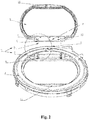
Fig. 2 is an exploded view of a lid structure of the present disclosure. -
Fig. 3 is an enlarged view at A ofFig. 2 . - Reference signs: 1 - slide groove, 2 - elastic support, 3 - cover, 4 - seat, 5 - restraint slot, 6 - rigid ball, 7 - spring, 8 - mounting hole, 9 - damper buffer structure, 10 - magnet, 11 - iron sheet, 12 - turning shaft.
- Specific embodiments of the present disclosure are further described in detail below in conjunction with the accompanying drawings.
- For most washing machines at present, after a lid is opened, the angle between cover and a horizontal direction is controlled to be equal to or slightly larger than 90 degrees, and a gravity center position is controlled so that the lid is in a vertical state after being opened. In this way, the lid is very likely to be automatically closed, and the lid strikes a seat while being closed to generate a noise and cause inconvenience for taking out clothes. In order to solve the above problem, in the present disclosure, a hinge of a washing machine is provided with a structure for positioning after a lid is opened, so that the lid, when being completely opened, is in a stable clamped state and not likely to be freely closed.
- The present disclosure provides an opening and closing lid structure of a washing machine, the opening and closing lid structure includes a cover, a seat and a control device. A turning
shaft 12 of thecover 3 is mounted to theseat 4, wherein the control device includes a slide groove 1 and anelastic support 2; the slide groove 1 is arranged on the turningshaft 12 of the cover along a rotating direction. A lower end of theelastic support 2 is mounted to theseat 4, and an upper end is slidably supported in the slide groove 1. The slide groove 1 is provided with arestraint slot 5 therein, into which theelastic support 2 slides to prevent thecover 3 from automatic closing after being opened. When thecover 3 is being opened, theelastic support 2 slides in the slide groove 1; and when thecover 3 is opened to the largest angle, theelastic support 2 is pushed into therestraint slot 5 and supported in therestraint slot 5 to prevent free closure of thecover 3. - The
elastic support 2 includes a rigid ball 6 and aspring 7, one end of the rigid ball 6 is supported on thespring 7 and the other end of the rigid ball 6 is supported in the slide groove 1, and thespring 7 is supported on theseat 4. Supported by thespring 7, the rigid ball 6 abuts against the slide groove 1, and in this case, thespring 7 is in a compressed state; and when the cover is opened to the largest angle, the rigid ball 6, supported by thespring 7, abuts against therestraint slot 5, and in this case, thespring 7 is in a compressed state. - A
mounting hole 8 for theelastic support 2 is formed at a position on theseat 4 facing the turningshaft 12. One end of theelastic support 2 is arranged in themounting hole 8, and the other end of the elastic support faces the turningshaft 12 and is supported in the slide groove 1. Most thespring 7 and the rigid ball 6 are located in themounting hole 8, and a part of the rigid ball 6 is exposed from themounting hole 8 and the slide groove 1, or therestraint slot 5. - From complete closure of the
cover 3 to turning to the largest angle of thecover 3, the slide groove 1 is at least covers a movement region of theelastic support 2 on the turningshaft 12. And the slide groove 1 is a smooth guide rail recessed toward to the interior of the turningshaft 12. The slide groove 1 can be so formed as to encircle theturnover shaft 12 along the rotating direction, but from complete closure of thecover 3 to turning to the largest angle of thecover 3, only the part of slide groove 1coversthemovement region of theelastic support 2 on the turningshaft 12 functions. So from the complete closure of thecover 3 to turning to the largest angle of thecover 3, the slide groove 1at least covers a movement region of theelastic support 2 on the turning shaft 12.And the slide groove 1 is a smooth guide rail recessed toward the interior of the turning shaft, to ensure sliding of the rigid ball 6 in the slide groove 1. - A first restraint slot is formed at a position on the slide groove 1 right facing the
elastic support 2 when thecover 3 is turned to the largest angle. When the cover is turned to the largest angle, the rigid ball of theelastic support 2 is right popped into the first restraint slot to limit the cover in this position. So that the cover, when being completely opened, is in a stable clamped state and cannot be freely closed. Thus, it facilitates users taking out clothes, and impact and striking between the cover and the seat in automatic closure are avoided. - A second restraint slot is formed at a position on the slide groove 1 just facing the
elastic support 2 when the cover is completely closed. When the cover is completely closed, the rigid ball 6 of theelastic support 2 is just pushed into the second restraint slot to limit the cover in this position, so that the cover, when being completely closed, is in a stable clamped state and can be opened with a slight force, which can avoid generating a noise by collision between the cover and the seat caused by shaking of the washing machine during dewatering. - The
restraint slot 5 is a recess that is recessed toward to the interior of the turningshaft 12 and matched with the rigid ball, and the recess and the slide groove have a smooth transition there between. This ensures a smooth and stable transition of the rigid ball between the restraint slot and the slide groove, to avoid very large vibration. - The turning
shaft 12 is further provided with adamper buffer structure 9 therein, to ensure the cover to produce a buffering effect during closure thereof so as not to generate a noise. And a magnet/iron sheet is arranged at the foremost end of the cover, such that under the effect of a magnetic force of the magnet, the cover can be well fixed to the seat and can be opened with a slight force, which can avoid to generate a noise by collision between the cover and the seat caused by shaking of the washing machine during dewatering. - The operating principle of the positioning structure for the cover in the present disclosure is as follows: the
spring 7 is mounted into themounting hole 8 of theseat 4, and the rigid ball 6 is mounted to the slide groove 1 which is below thecover 3 and together with the cover as a whole to mount on the seat 4.It is ensured that the rigid ball 6 is mounted to the spring 7.Such that when the cover is in a closed state, thespring 7 is in a compressed state, and the rigid ball 6 is located in the slide groove 1 or in the second restraint slot. And during opening of the cover, the rigid ball slides along the slide rail below the cover, and when the rigid ball just slides to the first restraint slot of the cover slide groove, the cover is completely opened. And the rigid ball is clamped into the first restraint slot, so that the cover comes into a stable, completely vertical state. - In the present disclosure, the
damper buffer structure 9 is mounted into the turningshaft 12 of the cover, which can ensure thecover 3 is under a buffering effect during closure thereof so as not to generate a noise. Themagnet 10 is mounted to the cover, and theiron sheet 11 is mounted to theseat 4, such that under the effect of a magnetic force of the magnet, thecover 3 can be well fixed to theseat 4. - An outstanding feature of this structure is using the spring, the rigid ball and the rigid ball slide groove structure to solve the problem that after being opened, the cover of the washing machine is very likely to be automatically closed to cause inconvenience for taking out clothes.
- The present disclosure provides a washing machine with the opening and closing lid structure described above. When the cover is completely closed, the cover is in a stable clamped state and can be opened with a slight force, which can avoid generating a noise by collision between the cover and the seat caused by shaking of the washing machine during dewatering. When the cover is completely opened, the cover is in a stable clamped state and not liable to be closed, which facilitates taking out clothes, and can avoid impacting and striking the seat in automatic closure of the cover.
- Described above are only preferred embodiments of the present disclosure, and it should be noted that to those of ordinary skill in the art, various modifications and improvements may also be made without departing from principles of the present disclosure, and these modifications and improvements should also be encompassed within the protection scope of the present disclosure.
Claims (10)
- An opening and closing lid structure of a washing machine, comprising a cover, a seat and a control device, a turning shaft of the cover being mounted to the seat,
wherein the control device includes a slide groove and an elastic support;
the slide groove is arranged on the turning shaft of the cover along a rotating direction of the turning shaft;
a lower end of the elastic support is mounted to the seat, and an upper end is slidably supported in the slide groove; and
the slide groove is provided with a restraint slot therein, and the elastic support slides into the restraint slot to prevent the cover from automatic closure after being opened. - The opening and closing lid structure of a washing machine according to claim 1, wherein the elastic support comprises a rigid ball and a spring, the rigid ball is supported on the spring and is supported in the slide groove, and the spring is supported on the seat.
- The opening and closing lid structure of a washing machine according to claim 2, wherein the spring is in a pre-compressed state.
- The opening and closing lid structure of a washing machine according to any one of claims 1-3, wherein a mounting hole for the elastic support is formed at a position on the seat facing the turning shaft,
one end of the elastic support is arranged in the mounting hole, and another end of the elastic support faces the turning shaft and is supported in the slide groove. - The opening and closing lid structure of a washing machine according to any one of claims 1-4, wherein from a complete closure of the cover to turning to the largest angle of the cover, the slide groove at least covers a movement region of the elastic support on the turning shaft, and the slide groove is a smooth guide rail recessed toward to an interior of the turning shaft.
- The opening and closing lid structure of a washing machine according to any one of claims 1-5, wherein a first restraint slot is formed at a position on the slide groove right facing the elastic support when the cover is turned to a largest angle.
- The opening and closing lid structure of a washing machine according to any one of claims 1-6, wherein a second restraint slot is formed at a position on the slide groove right facing the elastic support when the cover is completely closed.
- The opening and closing lid structure of a washing machine according to claim 6 or 7, wherein the restraint slot is a recess that is recessed toward to the interior of the turning shaft and is matched with the rigid ball, and the recess and the slide groove have a smooth transition there between.
- The opening and closing lid structure of a washing machine according to any one of claims 1-8, wherein a magnet or an iron sheet is arranged at a foremost end of the cover, and an iron sheet or a magnet is arranged at a corresponding position of the seat.
- A washing machine with the opening and closing lid structure according to any one of claims 1-9.
Applications Claiming Priority (2)
| Application Number | Priority Date | Filing Date | Title |
|---|---|---|---|
| CN201510268298.9A CN106283511B (en) | 2015-05-22 | 2015-05-22 | A washing machine cover opening and closing structure and washing machine |
| PCT/CN2016/079408 WO2016188264A1 (en) | 2015-05-22 | 2016-04-15 | Open lid/closed lid structure of washing machine and washing machine |
Publications (2)
| Publication Number | Publication Date |
|---|---|
| EP3299510A1 true EP3299510A1 (en) | 2018-03-28 |
| EP3299510A4 EP3299510A4 (en) | 2018-05-30 |
Family
ID=57392507
Family Applications (1)
| Application Number | Title | Priority Date | Filing Date |
|---|---|---|---|
| EP16799153.8A Withdrawn EP3299510A4 (en) | 2015-05-22 | 2016-04-15 | Open lid/closed lid structure of washing machine and washing machine |
Country Status (4)
| Country | Link |
|---|---|
| EP (1) | EP3299510A4 (en) |
| KR (1) | KR20180006983A (en) |
| CN (1) | CN106283511B (en) |
| WO (1) | WO2016188264A1 (en) |
Families Citing this family (4)
| Publication number | Priority date | Publication date | Assignee | Title |
|---|---|---|---|---|
| CN106835608A (en) * | 2017-04-13 | 2017-06-13 | 胡英瑛 | One kind can divide cavity washer |
| CN109423823A (en) * | 2017-08-31 | 2019-03-05 | 青岛海尔洗衣机有限公司 | A kind of inner barrel structure of washing machine and the washing machine using the interior bucket |
| CN107523970B (en) * | 2017-09-18 | 2022-07-08 | 佛山市顺德海尔电器有限公司 | Washing machine cover body opening and closing structure and washing machine |
| CN116065361B (en) * | 2021-11-01 | 2025-05-30 | 无锡小天鹅电器有限公司 | Door cover assembly for washing machine and clothes treatment equipment with door cover assembly |
Family Cites Families (18)
| Publication number | Priority date | Publication date | Assignee | Title |
|---|---|---|---|---|
| KR920020004A (en) * | 1991-04-30 | 1992-11-20 | 이헌조 | Automatic opening and closing method of the washing machine lid |
| KR100263449B1 (en) * | 1998-03-05 | 2000-08-01 | 윤종용 | Washing machine |
| JP2000167290A (en) * | 1998-12-07 | 2000-06-20 | Toshiba Corp | Washing machine |
| DE60331649D1 (en) * | 2003-09-25 | 2010-04-22 | Candy Spa | Electric household appliance with door to closing an interior |
| AU2008202220B2 (en) * | 2007-05-28 | 2010-12-02 | Lg Electronics Inc. | Laundry machine |
| JP4513877B2 (en) * | 2008-03-04 | 2010-07-28 | パナソニック株式会社 | Washing machine lid structure |
| EP2481845B1 (en) * | 2008-03-31 | 2014-06-11 | Electrolux Home Products Corporation N.V. | Electrical appliance with an improved door mechanism |
| WO2011109235A1 (en) * | 2010-03-01 | 2011-09-09 | Illinois Tool Works Inc. | Lid lock with magnetic anti-tamper feature |
| US8936330B2 (en) * | 2010-12-23 | 2015-01-20 | Lg Electronics Inc. | Laundry treating apparatus |
| KR101821202B1 (en) * | 2010-12-23 | 2018-03-08 | 엘지전자 주식회사 | Clothes Traeting Apparatus |
| CN202450899U (en) * | 2012-01-19 | 2012-09-26 | 中国新兴保信建设总公司 | Multi-angle positioning device of side hung door |
| CN202576941U (en) * | 2012-04-28 | 2012-12-05 | 海信容声(广东)冰箱有限公司 | Automatic uncapping device of washing machine barrel cover and washing machine |
| CN202671904U (en) * | 2012-07-09 | 2013-01-16 | 海信容声(广东)冰箱有限公司 | Washing machine door cover and washing machine |
| CN203175222U (en) * | 2013-04-25 | 2013-09-04 | 李瑶兴 | Locating door strip |
| CN203412416U (en) * | 2013-07-29 | 2014-01-29 | 李福青 | Graded opening device of protective cover |
| CN203808676U (en) * | 2014-04-10 | 2014-09-03 | 吴江市赛纳电子科技有限公司 | Positioning opening and closing device |
| CN204002175U (en) * | 2014-07-29 | 2014-12-10 | 浙江泰鸿机电有限公司 | The door stop of motor vehicle |
| CN204059016U (en) * | 2014-08-25 | 2014-12-31 | 宁波奇帅电器有限公司 | A kind of cover plate for washing machine |
-
2015
- 2015-05-22 CN CN201510268298.9A patent/CN106283511B/en active Active
-
2016
- 2016-04-15 WO PCT/CN2016/079408 patent/WO2016188264A1/en not_active Ceased
- 2016-04-15 EP EP16799153.8A patent/EP3299510A4/en not_active Withdrawn
- 2016-04-15 KR KR1020177036962A patent/KR20180006983A/en not_active Ceased
Also Published As
| Publication number | Publication date |
|---|---|
| KR20180006983A (en) | 2018-01-19 |
| CN106283511A (en) | 2017-01-04 |
| WO2016188264A1 (en) | 2016-12-01 |
| EP3299510A4 (en) | 2018-05-30 |
| CN106283511B (en) | 2022-04-05 |
Similar Documents
| Publication | Publication Date | Title |
|---|---|---|
| AU2009287381B2 (en) | Drive device for a furniture flap | |
| KR101920970B1 (en) | Door hinge | |
| EP4464863A2 (en) | Refrigerator | |
| KR200459745Y1 (en) | a hinge apparatus | |
| EP4424963A1 (en) | Monotrack embedded hinge automatic door-closing mechanism | |
| CN106283511B (en) | A washing machine cover opening and closing structure and washing machine | |
| CN110968160A (en) | a multifunction machine | |
| AU2001266468A1 (en) | A lid closing arrangement | |
| CN114704171A (en) | Friction retaining mechanism for hinge | |
| CN110512971B (en) | Durable household silent door stopper | |
| CN106460436B (en) | Hinges for furniture or household appliances | |
| CN105155962A (en) | Acting force auxiliary structure of upturning device | |
| CN106091523A (en) | A kind of refrigerator display panel concealed structure and refrigerator | |
| JP2020056235A (en) | Arm stopper | |
| CN203684879U (en) | Positioning self-sliding closing door shaft and cabinet comprising same | |
| CN212454057U (en) | Flip structure and cupboard | |
| CN103347145A (en) | Switch and angle adjusting mechanism and household appliance | |
| CN204048738U (en) | A kind of sliding rail buffering mechanism | |
| KR101267339B1 (en) | Hinge device of door for washing machine | |
| JP2010077706A (en) | Cover opening/closing mechanism | |
| KR101013742B1 (en) | Hinge Assembly for Mobile Communication Terminal | |
| CN221615332U (en) | Shell structure and processing device | |
| KR100313579B1 (en) | Device for opening one touch of folder type handphone | |
| CN209590491U (en) | A kind of rotary shutter equipped with buffer gear | |
| CN202000159U (en) | Washing machine door closure with linear damper |
Legal Events
| Date | Code | Title | Description |
|---|---|---|---|
| STAA | Information on the status of an ep patent application or granted ep patent |
Free format text: STATUS: THE INTERNATIONAL PUBLICATION HAS BEEN MADE |
|
| PUAI | Public reference made under article 153(3) epc to a published international application that has entered the european phase |
Free format text: ORIGINAL CODE: 0009012 |
|
| STAA | Information on the status of an ep patent application or granted ep patent |
Free format text: STATUS: REQUEST FOR EXAMINATION WAS MADE |
|
| 17P | Request for examination filed |
Effective date: 20171222 |
|
| AK | Designated contracting states |
Kind code of ref document: A1 Designated state(s): AL AT BE BG CH CY CZ DE DK EE ES FI FR GB GR HR HU IE IS IT LI LT LU LV MC MK MT NL NO PL PT RO RS SE SI SK SM TR |
|
| AX | Request for extension of the european patent |
Extension state: BA ME |
|
| A4 | Supplementary search report drawn up and despatched |
Effective date: 20180502 |
|
| RIC1 | Information provided on ipc code assigned before grant |
Ipc: D06F 37/28 20060101ALN20180424BHEP Ipc: D06F 39/14 20060101AFI20180424BHEP |
|
| DAV | Request for validation of the european patent (deleted) | ||
| DAX | Request for extension of the european patent (deleted) | ||
| STAA | Information on the status of an ep patent application or granted ep patent |
Free format text: STATUS: THE APPLICATION IS DEEMED TO BE WITHDRAWN |
|
| 18D | Application deemed to be withdrawn |
Effective date: 20181129 |