EP3299299A1 - Apparatus and method of compensating for relative motion of at least two aircraft-mounted cameras - Google Patents
Apparatus and method of compensating for relative motion of at least two aircraft-mounted cameras Download PDFInfo
- Publication number
- EP3299299A1 EP3299299A1 EP17193259.3A EP17193259A EP3299299A1 EP 3299299 A1 EP3299299 A1 EP 3299299A1 EP 17193259 A EP17193259 A EP 17193259A EP 3299299 A1 EP3299299 A1 EP 3299299A1
- Authority
- EP
- European Patent Office
- Prior art keywords
- wing
- aircraft
- camera
- cameras
- orientation
- Prior art date
- Legal status (The legal status is an assumption and is not a legal conclusion. Google has not performed a legal analysis and makes no representation as to the accuracy of the status listed.)
- Granted
Links
Images



Classifications
-
- H—ELECTRICITY
- H04—ELECTRIC COMMUNICATION TECHNIQUE
- H04N—PICTORIAL COMMUNICATION, e.g. TELEVISION
- H04N13/00—Stereoscopic video systems; Multi-view video systems; Details thereof
- H04N13/20—Image signal generators
- H04N13/204—Image signal generators using stereoscopic image cameras
- H04N13/246—Calibration of cameras
-
- H—ELECTRICITY
- H04—ELECTRIC COMMUNICATION TECHNIQUE
- H04N—PICTORIAL COMMUNICATION, e.g. TELEVISION
- H04N23/00—Cameras or camera modules comprising electronic image sensors; Control thereof
- H04N23/60—Control of cameras or camera modules
- H04N23/68—Control of cameras or camera modules for stable pick-up of the scene, e.g. compensating for camera body vibrations
- H04N23/682—Vibration or motion blur correction
- H04N23/685—Vibration or motion blur correction performed by mechanical compensation
-
- B—PERFORMING OPERATIONS; TRANSPORTING
- B64—AIRCRAFT; AVIATION; COSMONAUTICS
- B64D—EQUIPMENT FOR FITTING IN OR TO AIRCRAFT; FLIGHT SUITS; PARACHUTES; ARRANGEMENT OR MOUNTING OF POWER PLANTS OR PROPULSION TRANSMISSIONS IN AIRCRAFT
- B64D47/00—Equipment not otherwise provided for
- B64D47/08—Arrangements of cameras
-
- B—PERFORMING OPERATIONS; TRANSPORTING
- B64—AIRCRAFT; AVIATION; COSMONAUTICS
- B64U—UNMANNED AERIAL VEHICLES [UAV]; EQUIPMENT THEREFOR
- B64U20/00—Constructional aspects of UAVs
- B64U20/80—Arrangement of on-board electronics, e.g. avionics systems or wiring
- B64U20/87—Mounting of imaging devices, e.g. mounting of gimbals
-
- G—PHYSICS
- G05—CONTROLLING; REGULATING
- G05D—SYSTEMS FOR CONTROLLING OR REGULATING NON-ELECTRIC VARIABLES
- G05D1/00—Control of position, course, altitude or attitude of land, water, air or space vehicles, e.g. using automatic pilots
- G05D1/10—Simultaneous control of position or course in three dimensions
- G05D1/101—Simultaneous control of position or course in three dimensions specially adapted for aircraft
- G05D1/106—Change initiated in response to external conditions, e.g. avoidance of elevated terrain or of no-fly zones
-
- G—PHYSICS
- G06—COMPUTING OR CALCULATING; COUNTING
- G06T—IMAGE DATA PROCESSING OR GENERATION, IN GENERAL
- G06T7/00—Image analysis
- G06T7/30—Determination of transform parameters for the alignment of images, i.e. image registration
- G06T7/32—Determination of transform parameters for the alignment of images, i.e. image registration using correlation-based methods
-
- G—PHYSICS
- G06—COMPUTING OR CALCULATING; COUNTING
- G06T—IMAGE DATA PROCESSING OR GENERATION, IN GENERAL
- G06T7/00—Image analysis
- G06T7/50—Depth or shape recovery
- G06T7/55—Depth or shape recovery from multiple images
- G06T7/593—Depth or shape recovery from multiple images from stereo images
-
- G—PHYSICS
- G06—COMPUTING OR CALCULATING; COUNTING
- G06V—IMAGE OR VIDEO RECOGNITION OR UNDERSTANDING
- G06V20/00—Scenes; Scene-specific elements
- G06V20/10—Terrestrial scenes
- G06V20/13—Satellite images
-
- G—PHYSICS
- G06—COMPUTING OR CALCULATING; COUNTING
- G06V—IMAGE OR VIDEO RECOGNITION OR UNDERSTANDING
- G06V20/00—Scenes; Scene-specific elements
- G06V20/10—Terrestrial scenes
- G06V20/17—Terrestrial scenes taken from planes or by drones
-
- G—PHYSICS
- G08—SIGNALLING
- G08G—TRAFFIC CONTROL SYSTEMS
- G08G5/00—Traffic control systems for aircraft
- G08G5/20—Arrangements for acquiring, generating, sharing or displaying traffic information
- G08G5/21—Arrangements for acquiring, generating, sharing or displaying traffic information located onboard the aircraft
-
- G—PHYSICS
- G08—SIGNALLING
- G08G—TRAFFIC CONTROL SYSTEMS
- G08G5/00—Traffic control systems for aircraft
- G08G5/70—Arrangements for monitoring traffic-related situations or conditions
- G08G5/72—Arrangements for monitoring traffic-related situations or conditions for monitoring traffic
- G08G5/723—Arrangements for monitoring traffic-related situations or conditions for monitoring traffic from the aircraft
-
- G—PHYSICS
- G08—SIGNALLING
- G08G—TRAFFIC CONTROL SYSTEMS
- G08G5/00—Traffic control systems for aircraft
- G08G5/80—Anti-collision systems
-
- H—ELECTRICITY
- H04—ELECTRIC COMMUNICATION TECHNIQUE
- H04N—PICTORIAL COMMUNICATION, e.g. TELEVISION
- H04N13/00—Stereoscopic video systems; Multi-view video systems; Details thereof
- H04N13/20—Image signal generators
- H04N13/204—Image signal generators using stereoscopic image cameras
- H04N13/239—Image signal generators using stereoscopic image cameras using two two-dimensional [2D] image sensors having a relative position equal to or related to the interocular distance
-
- H—ELECTRICITY
- H04—ELECTRIC COMMUNICATION TECHNIQUE
- H04N—PICTORIAL COMMUNICATION, e.g. TELEVISION
- H04N13/00—Stereoscopic video systems; Multi-view video systems; Details thereof
- H04N13/20—Image signal generators
- H04N13/204—Image signal generators using stereoscopic image cameras
- H04N13/243—Image signal generators using stereoscopic image cameras using three or more two-dimensional [2D] image sensors
-
- H—ELECTRICITY
- H04—ELECTRIC COMMUNICATION TECHNIQUE
- H04N—PICTORIAL COMMUNICATION, e.g. TELEVISION
- H04N23/00—Cameras or camera modules comprising electronic image sensors; Control thereof
- H04N23/90—Arrangement of cameras or camera modules, e.g. multiple cameras in TV studios or sports stadiums
-
- B—PERFORMING OPERATIONS; TRANSPORTING
- B64—AIRCRAFT; AVIATION; COSMONAUTICS
- B64D—EQUIPMENT FOR FITTING IN OR TO AIRCRAFT; FLIGHT SUITS; PARACHUTES; ARRANGEMENT OR MOUNTING OF POWER PLANTS OR PROPULSION TRANSMISSIONS IN AIRCRAFT
- B64D45/00—Aircraft indicators or protectors not otherwise provided for
- B64D2045/0095—Devices specially adapted to avoid bird strike
-
- B—PERFORMING OPERATIONS; TRANSPORTING
- B64—AIRCRAFT; AVIATION; COSMONAUTICS
- B64D—EQUIPMENT FOR FITTING IN OR TO AIRCRAFT; FLIGHT SUITS; PARACHUTES; ARRANGEMENT OR MOUNTING OF POWER PLANTS OR PROPULSION TRANSMISSIONS IN AIRCRAFT
- B64D45/00—Aircraft indicators or protectors not otherwise provided for
- B64D45/04—Landing aids; Safety measures to prevent collision with earth's surface
- B64D45/08—Landing aids; Safety measures to prevent collision with earth's surface optical
-
- B—PERFORMING OPERATIONS; TRANSPORTING
- B64—AIRCRAFT; AVIATION; COSMONAUTICS
- B64U—UNMANNED AERIAL VEHICLES [UAV]; EQUIPMENT THEREFOR
- B64U2101/00—UAVs specially adapted for particular uses or applications
- B64U2101/30—UAVs specially adapted for particular uses or applications for imaging, photography or videography
-
- G—PHYSICS
- G06—COMPUTING OR CALCULATING; COUNTING
- G06T—IMAGE DATA PROCESSING OR GENERATION, IN GENERAL
- G06T2207/00—Indexing scheme for image analysis or image enhancement
- G06T2207/10—Image acquisition modality
- G06T2207/10004—Still image; Photographic image
- G06T2207/10012—Stereo images
-
- G—PHYSICS
- G06—COMPUTING OR CALCULATING; COUNTING
- G06T—IMAGE DATA PROCESSING OR GENERATION, IN GENERAL
- G06T2207/00—Indexing scheme for image analysis or image enhancement
- G06T2207/10—Image acquisition modality
- G06T2207/10024—Color image
-
- G—PHYSICS
- G06—COMPUTING OR CALCULATING; COUNTING
- G06T—IMAGE DATA PROCESSING OR GENERATION, IN GENERAL
- G06T2207/00—Indexing scheme for image analysis or image enhancement
- G06T2207/10—Image acquisition modality
- G06T2207/10032—Satellite or aerial image; Remote sensing
-
- G—PHYSICS
- G06—COMPUTING OR CALCULATING; COUNTING
- G06T—IMAGE DATA PROCESSING OR GENERATION, IN GENERAL
- G06T2207/00—Indexing scheme for image analysis or image enhancement
- G06T2207/30—Subject of image; Context of image processing
- G06T2207/30248—Vehicle exterior or interior
- G06T2207/30252—Vehicle exterior; Vicinity of vehicle
-
- G—PHYSICS
- G06—COMPUTING OR CALCULATING; COUNTING
- G06T—IMAGE DATA PROCESSING OR GENERATION, IN GENERAL
- G06T2207/00—Indexing scheme for image analysis or image enhancement
- G06T2207/30—Subject of image; Context of image processing
- G06T2207/30248—Vehicle exterior or interior
- G06T2207/30252—Vehicle exterior; Vicinity of vehicle
- G06T2207/30261—Obstacle
-
- G—PHYSICS
- G06—COMPUTING OR CALCULATING; COUNTING
- G06V—IMAGE OR VIDEO RECOGNITION OR UNDERSTANDING
- G06V20/00—Scenes; Scene-specific elements
- G06V20/50—Context or environment of the image
- G06V20/56—Context or environment of the image exterior to a vehicle by using sensors mounted on the vehicle
- G06V20/58—Recognition of moving objects or obstacles, e.g. vehicles or pedestrians; Recognition of traffic objects, e.g. traffic signs, traffic lights or roads
Definitions
- the present application relates to aircraft-mounted cameras, and is particularly directed to apparatus and method of compensating for relative motion of at least two aircraft-mounted cameras.
- An aircraft may include two cameras that are used as part of an object detection and collision avoidance system, for example.
- one camera can be mounted on a portion of an aircraft wing, and the other camera can be mounted on a portion of another aircraft wing. Since the aircraft wings flex and the cameras are relatively far apart from each other, the distance and orientation between the cameras can vary greatly due to wing vibrations, for example, during flight. As a result of the variations in distance and orientation between the cameras, the system is unable to stereoscopically accurately determine the position of an object, such as a bird, approaching the aircraft to avoid a collision with the object. It would be desirable to provide an apparatus and method in which the varying distances and orientations between the two aircraft-mounted cameras are compensated so that the system is able to accurately determine the position of an object approaching the aircraft.
- a method of compensating for variations in distance and orientation between first and second wing-mounted cameras of an aircraft due to flexing of at least one aircraft wing.
- the method comprises determining a first distance and orientation between the first wing-mounted camera and the second wing-mounted camera during a neutral wing condition of the aircraft, determining a second distance and orientation between the first wing-mounted camera and the second wing-mounted camera during a flexed wing condition of the aircraft, and processing the difference between the first and second distances and orientations to provide a real-time varying distance and orientation for use in providing a compensated distance between the first and second wing-mounted cameras.
- a method is provided of processing image data captured by a left wing-mounted camera of an aircraft and a right wing-mounted camera of the aircraft to compensate for variations in distance and orientation between the cameras due to flexing of left and right aircraft wings.
- the method comprises correlating captured images from the left wing-mounted camera against a left nose template associated with a left aircraft wing, transforming image data from at least one image frame captured by the left wing-mounted camera to eliminate relative motion associated with motion of the left aircraft wing, correlating captured images from the right wing-mounted camera against a right nose template associated with a right aircraft wing, and transforming image data from at least one image frame captured by the right wing-mounted camera to eliminate relative motion associated with motion of the right aircraft wing.
- an apparatus for an aircraft-mounted object detection and collision avoidance system.
- the apparatus comprises a first camera attached to one portion of the aircraft and a second camera attached to another portion of the aircraft.
- the first and second cameras cooperate to captures images of an object in a flight path.
- the apparatus further comprises a motion compensation module configured to calculate a real-time distance and orientation between the first camera and the second camera.
- the apparatus also comprises a detection module configured to calculate a distance between the aircraft and the object based upon the calculated real-time distance between the first camera and the second camera.
- the present application is directed to an apparatus and method of compensating for relative motion of at least two aircraft-mounted cameras.
- the specific apparatus, motion compensation methods, and the industry in which the apparatus and motion compensation methods are implemented may vary. It is to be understood that the disclosure below provides a number of embodiments or examples for implementing different features of various embodiments. Specific examples of components and arrangements are described to simplify the present disclosure. These are merely examples and are not intended to be limiting.
- FAA Federal Aviation Administration
- an aircraft-mounted object detection and collision avoidance system embodying an apparatus in accordance with an example implementation, may be used in association with a vehicle 12.
- the vehicle 12 may be moving along a path (e.g., in the direction indicated by direction arrow 14).
- An object 16 may be moving along a path (e.g., in a direction indicated by arrow 18).
- the object 16 may impact with (e.g., strike) the vehicle 12.
- the vehicle 12 and object 16 may not necessarily be shown to scale in Fig. 1 .
- the vehicle 12 may be any type of aircraft 30.
- the aircraft 30 may be a fixed wing, a rotary wing, or a lighter than air aircraft.
- the aircraft 30 may be manned or unmanned.
- the aircraft 30 may be a commercial passenger aircraft operated by an airline, a cargo aircraft operated by a private or public entity, a military aircraft operated by a military or other government organization, a personal aircraft operated by an individual, or any other type of aircraft operated by any other aircraft operator.
- the aircraft 30 may be an unmanned aerial vehicle (UAV) operated by a remote operator.
- UAV unmanned aerial vehicle
- the vehicle 12 e.g., aircraft 30
- the vehicle 12 may be designed to perform any mission and may be operated by any operator of the vehicle 12.
- the object 16 may be any object that may potentially strike the vehicle 12.
- the object 16 may be any moving airborne object moving along the path 18 that may intersect the path 14 of the vehicle 12.
- the object 16 may be a bird 34.
- the object 16 may be another aircraft, or any other airborne man-made or natural object.
- the terms “strike”, “struck”, “collision”, “collide” and any similar or related terms may refer to the impact of the vehicle 12 and the object 16.
- the phrase “an object striking or potentially striking a vehicle” may refer to a moving vehicle 12 impacting with a moving object 16 (e.g., an airborne object).
- the system 10 may include at least one image capture module 20.
- the image capture module 20 may be connected to the vehicle 12 (e.g., aircraft 30) shown in Fig. 1 .
- the image capture module 20 includes at least two cameras 21, 22 configured to obtain image data representative of images 24.
- each of the at least two cameras 21, 22 comprises a wide field of view camera (i.e., greater than 90 degrees).
- the at least two cameras 21, 22 may include the same type of cameras or a number of different types of cameras.
- the at least two cameras 21, 22 may include one or more video cameras. For simplicity and clarity of discussion, only the two cameras 21, 22 will be discussed herein.
- the two cameras 21, 22 may operate over any range or ranges of wavelengths and/or frequencies to obtain images 24 (e.g., video images 26).
- the two cameras 21, 22 may be configured to obtain images 24 at infrared, near infrared, visible, ultraviolet, other wavelengths, or combinations of wavelengths.
- the two cameras 21, 22 may be configured to obtain images 24 from light that is polarized.
- the two cameras 21, 22 may include one or more long-wavelength infrared (“LWIR”) cameras.
- the two cameras 21, 22 may include one or more med-wavelength infrared (“MWIR”) cameras.
- the two cameras 21, 22 may include one or more short-wavelength infrared (“SWIR”) cameras.
- the two cameras 21, 22 may include a combination of one or more long-wavelength infrared cameras, med-wavelength infrared cameras, and short-wavelength infrared cameras.
- the images 24 may be video images 26.
- the video images 26 may include a sequential series of digital video image frames taken rapidly over a period of time (e.g., 30 Hz).
- the images 24 provided by the two cameras 21, 22 may be used to detect the presence of one or more objects 16 and to identify one or more characteristics of the object 16.
- the image capture module 20 may include a field of view 40.
- the two cameras 21, 22 may include the field of view 40.
- the two cameras 21, 22 may be mounted on the vehicle 12 looking forwardly and having an unobstructed field of view 40 (e.g., the field of view 40 not obstructed by the vehicle 12).
- the field of view 40 may be defined by a target area 15 in front of the vehicle 12 (e.g., aircraft 30) between lines 28 and 29 (e.g., in the direction of movement 14 of the vehicle 12).
- the target area 15 may include a cone extending forward of the vehicle 12.
- the object 16 e.g., the bird 34
- the images 24 from the at least two cameras 22 may include images of the object 16.
- the two cameras 21, 22 may include a combined field of view. In another example implementation, the two cameras 21, 22 may include an overlapping field of view 27. For example, the two cameras 21, 22 may be used including an overlapping field of view 27 in order for the system 10 to determine the distance of the object 16 relative to the vehicle 12 using a stereo solution (e.g., stereo vision).
- a stereo solution e.g., stereo vision
- the two cameras 21, 22 may be mounted to the vehicle 12 at any suitable or appropriate location.
- one camera 21 is mounted to the end of one wing 31 of the aircraft 30 and the other camera 22 is mounted to the end of the other wing 32 of the aircraft 30, as schematically shown in Fig. 1 .
- the two cameras 21, 22 may be mounted to the vehicle (e.g., aircraft 30) at any other suitable or appropriate location.
- the two cameras 21, 22 of the image capture module 20 may be connected to the vehicle 12 at various positions and orientations.
- the two cameras 21, 22 may face in any appropriate direction.
- the two cameras 21, 22 may generally face forward on the vehicle 12 (e.g., in the direction of movement 14) in order to view the object 16 in the path of the vehicle 12 or crossing the path of the vehicle 12 (e.g., within the field of view 40).
- the system 10 may include a detection module 50.
- the detection module 50 may be configured to receive the images 24 transmitted by the image capture module 20.
- the detection module 50 may be configured to process the images 24 and determine the presence of the object 16 and whether the object 16 is likely to strike the vehicle 12.
- the detection module 50 may also be configured to identify and/or determine various characteristics of the object 16 based on the images 24.
- the detection module 50 may also be configured to determine various characteristics of a potential strike.
- the motion compensation module 100 includes a processing unit 102 that executes instructions stored in an internal data storage unit 104, an external data storage unit (not shown), or a combination thereof.
- the processing unit 102 may comprise any type of technology.
- the processing unit 102 may comprise a dedicated-purpose electronic processor.
- Other types of processors and processing unit technologies are possible.
- the internal data storage unit 104 may comprise any type of technology.
- the internal data storage unit 104 may comprise random access memory (RAM), read only memory (ROM), solid state memory, or any combination thereof. Other types of memories and data storage unit technologies are possible.
- the motion compensation module 100 further includes a number of input/output (I/O) devices 106 that may comprise any type of technology.
- the I/O devices 106 may comprise a keypad, a keyboard, a touch-sensitive display screen, a liquid crystal display (LCD) screen, a microphone, a speaker, or any combination thereof.
- Other types of I/O devices and technologies are possible.
- the motion compensation module 100 processes the images 24 to compensate for variations in distance and orientation (e.g., rotation) between the two cameras 21, 22 mounted on the ends of the wings 31, 32 of the aircraft 30 due to flexing motion of at least one of the wings 31, 32. More specifically, the processing unit 102 executes instructions of a motion compensation program 105 stored in the data storage unit 104 to compensate for the variations in the distance and orientation between the two cameras 21, 22 due to the flexing motion of one or both of the wings 31, 32. Operation of the motion compensation module 100 is described hereinbelow.
- the image 300 shows a number of different features of the aircraft 30 visible form a camera mounted on the left wing.
- the features of the image 300 include passenger window features 33, aircraft door features 34, pilot window features 35, fuselage features 36, and aircraft livery features 37. These are only example features of the aircraft 30. Other types of features are possible.
- the features in the image 300 produce non-trivial correlations for purpose of relative motion compensation.
- the image 400 shows a number of different features of the aircraft 30 visible from a camera mounted on the right wing.
- the features of the image 400 include passenger window features 43, aircraft door features 44, pilot window features 45, fuselage features 46, and aircraft livery features 47. These are only example features of the aircraft 30. Other types of features are possible.
- the features in the image 400 produce non-trivial correlations for purpose of relative motion compensation.
- the image 300 from the camera 21 on the left aircraft wing 31 and the image 400 from the camera 22 on the right aircraft wing 32 are similar.
- the two images 300, 400 are processed by the motion compensation module 100 in the same way.
- image processing of the image 400 from the camera 22 on the right aircraft wing 32 will be described in detail. It is understood that the same image processing details apply to the camera 21 on the left aircraft wing 31.
- an image 510 from the camera 22 mounted on the right aircraft wing 32 with no right-wing motion is illustrated.
- This is the reference image of the right side of the aircraft, and is the image that all in-flight images from the right wing camera are correlated with to determine motion.
- This image is captured at the time of stereo calibration of the two, or more, cameras being used in the stereo ranging process.
- the tip of the nose of the aircraft 30 aligns parallel with an original horizontal reference line 512 (shown as a dashed line).
- the nose of the aircraft 30 aligns perpendicular with an original vertical reference line 514 (also shown as dashed line).
- FIG. 5B an image 520 from the camera 22 mounted on the right aircraft wing 32 with right-wing motion in the upward direction (as shown by arrow "A" in Fig. 5B ) is illustrated.
- the camera 22 captures a different image, which is shown as the image 520 in Fig. 5B .
- the image 520 shows the tip of the nose of the aircraft 30 and features of the aircraft 30 shifted downward (as shown by arrow "B” in Fig. 5B ).
- the tip of the nose of the aircraft 30 aligns with an offset horizontal reference line 516 (shown as a dashed line).
- This offset horizontal reference line 516 is offset from the original horizontal reference line 512 by a distance of "d" shown in Fig. 5B .
- the offset distance " d " depends upon a number of factors including the length of the right wing 32, for example.
- an image 530 from the camera 22 mounted on the right aircraft wing 32 with right-wing motion in a counter-clockwise twist direction (as shown by offset angle " ⁇ " in Fig. 5C ) is illustrated.
- the camera 22 mounted on the right aircraft wing 32 captures a different image, which is shown as the image 530 in Fig. 5C .
- the tip of the nose of the aircraft 30 pivots in a clockwise twist direction (as shown by offset angle " ⁇ " in the image 530 in Fig. 5C ).
- the offset angle of " ⁇ " in the image 530 and the offset angle " ⁇ " on the right wing 32 should be about the same.
- Figs. 5A, 5B , and 5C show a series of images captured by the camera 22 mounted on the right aircraft wing 32, and the effects of wing relative motion on the captured images.
- the image 510 of Fig. 5A shows no wing motion
- the image 520 of Fig. 5B shows an upward wing motion
- the image 530 of Fig. 5C shows a counter-clockwise twisting wing motion.
- Other motions are similarly determined.
- a compensated image 540 showing the effect of image transformation that removes the effect of wing relative motion of Figs. 5B , and 5C is illustrated.
- the compensated image 540 is the result of transforming the image 520 of Fig. 5B and transforming the image 530 of Fig. 5C .
- the compensated image 540 shows the offset distance of " d " in the image 520 ( Fig. 5B ) being reduced to zero, and shows the offset angle " ⁇ " in the image 530 ( Fig. 5C ) being reduced to zero.
- a flow diagram 700 depicts an object detection and collision avoidance method in which no motion compensation method is implemented.
- the left wing camera 21 continuously captures video frames of objects (e.g., birds in this example), and detects and segments the birds.
- the right wing camera 22 continuously captures video frames of the objects, and detects and segments the birds.
- the bird objects are associated in block 750.
- stereoscopic disparities are measured.
- bird ranges and bird range rates are computed as shown in block 770.
- the process then proceeds to block 780 in which bird collision metrics are computed. If a potential bird collision is determined based upon the bird collision metrics computer in block 780, then an alarm is provided to an operator as shown in block 790.
- C(T) can be calculated every video frame from the two cameras 21, 22 with T set to 10 seconds.
- the resulting integer C(10) could be used to drive an alarm which goes off when it increases from 0 to any non-zero value.
- the alarm increases in urgency as the number rises.
- a flow diagram 800 depicts the object detection and collision avoidance method of Fig. 7 in which a motion compensation method in accordance with an embodiment is implemented.
- a left nose template is correlated.
- an image from the left wing camera 21 is transformed based upon the correlated nose template of block 810 to eliminate the left wing motion (both up/down vertical motion and clockwise/counter-clockwise twist motion).
- a right nose template is correlated.
- an image from the right wing camera 22 is transformed based upon the correlated nose template of block 812 to eliminate the right wing motion (both up/down vertical motion and clockwise/counter-clockwise twist motion).
- the front part of the aircraft 30 is visible from each camera (each sees one side) of the at least two cameras 21, 22.
- the apparent location of the nose of the aircraft 30 changes.
- the change in apparent location of the nose of the aircraft 30 from the camera 22 can be tracked easily by constructing the right nose template and correlating captured images 24 from the camera 22 against the right nose template.
- the right nose template may comprise the captured image 510 shown in Fig. 5A , for example.
- the right nose template may comprise a black and white or color template, for example.
- Fig. 5B shows what happens with respect to the camera 22 on the right aircraft wing 32 with wing motion in an upward direction.
- Fig. 5C shows what happens with respect to the camera 22 on the right aircraft wing 32 with wing motion in a counter-clockwise twist.
- features of the aircraft 30, such as the features 43, 44, 45, 46, 47 shown in Fig. 4 , are used in the correlation against the right nose template, as shown in block 812 in Fig. 8 .
- the best features to correlate are those with large derivatives which all sum together to cause a correlation peak when the right nose template matches the current nose image.
- the movement of the correlation peak determines the movement (displacement) in two dimensional pixel space.
- This calibration step allows the creation of a fixed function p ( ) that maps pixel locations ( x, y ) to solid angle vectors ( ⁇ , ⁇ ), where ⁇ is the angle in x-y space (the reference ground plane of the airplane) and ⁇ is the elevation angle off of the reference ground plane of the airplane.
- p ( ) maps pixel locations ( x, y ) to solid angle vectors ( ⁇ , ⁇ ), where ⁇ is the angle in x-y space (the reference ground plane of the airplane) and ⁇ is the elevation angle off of the reference ground plane of the airplane.
- the above function is defined during final installation of the object detection and collision avoidance system 10 and updated at periodic calibration intervals.
- a coordinates diagram 900 of an example scenario showing (x, y, z) showing distance coordinates of the object 16 (i.e., the bird 34 in this example) relative to the camera 21 mounted on the left aircraft wing 31 and the camera 22 mounted on the right aircraft wing 32.
- the aircraft point of impact is at the center of the coordinates diagram 900 (i.e., at the (x, y, z) coordinates of (0, 0, 0).
- the point of nearest intersection c can be calculated as follows:
- the aircraft 30 is centered at location (0, 0, 0)
- the bird 34 is at location (800, -200, 100)
- the camera 21 on the left aircraft wing 31 is at location (-40, -120, 0)
- the camera 22 on the right aircraft wing 32 is at location (-40, -120, 0).
- each of the cameras 21, 22 has a 120 degrees field of view (FOV) in both horizontal and vertical directions.
- the pixel locations for the bird 34 in the left and right cameras 21, 22 can be expressed as follows: 500 ⁇ l ⁇ FOV 500 ⁇ l ⁇ FOV 500 ⁇ r ⁇ FOV 500 ⁇ r ⁇ FOV
- the above-identified pixel locations for the bird 34 in the left and right cameras 21, 22 are computed to be [-173.7872, 52.8997] and [-45.3361, 56.3223]. These pixel locations would be what an interpolated pixel location of an ideal camera would give. It should be noted that the previous pixel location calculations would not be done, but rather the bird 34 would be found within the pixel space of the camera image for each frame.
- the angles ⁇ l , ⁇ r , ⁇ l , ⁇ r in degrees would be as follows: ⁇ 20.8545 , ⁇ 5.4403 , 6.3480 , 6.7587
- Fig. 8 proceeds to blocks 830 and 840.
- the left wing camera 21 continuously captures video frames of objects (e.g., birds in this example), and detects and segments the birds.
- the right wing camera continuously captures video frames of the birds, and detects and segments the birds.
- the bird objects are associated in block 850.
- stereoscopic disparities are measured. Based upon the associated bird objects from block 850 and the stereoscopic disparities of the bird objects as measured in block 860, bird ranges and bird range rates are computed as shown in block 870.
- the bird range (i.e., BR) from the aircraft 30 can be calculated as norm of c or
- a 30 Hz frame rate i.e., FR
- Predicted bird strike events at any future time can be calculated using the above equation for BRR j .
- Fig. 8 then proceeds to block 880 in which bird collision metrics are computed. If a potential bird collision is determined based upon the bird collision metrics computed in block 880, then an alarm is provided to an operator as shown in block 890. However, if no potential bird collision is determined based upon the bird collision metrics computed in block 880, then the process returns back to block 810 and block 812 to process the next image frame for each of the left and right wing cameras 21, 22.
- Coded instructions to implement the motion compensation method may be stored in a mass storage device, in a volatile memory, in a non-volatile memory, and/or on a removable tangible computer readable storage medium such as a CD or DVD.
- the motion compensation method may be implemented using machine readable instructions that comprise a program for execution by a processor such as the processing unit 102 shown in the example motion compensation module 100 discussed above in connection with Fig. 1 .
- the program may be embodied in software stored on a tangible computer readable storage medium such as a CD-ROM, a floppy disk, a hard drive, a digital versatile disk (DVD), a Blu-ray disk, or a memory associated with the processing unit 102, but the entire program and/or parts thereof could alternatively be executed by a device other than the processing unit 102 and/or embodied in firmware or dedicated hardware.
- Many other methods of implementing the example motion compensation module 100 may alternatively be used.
- the order of execution of blocks may be changed, and/or some of blocks described with reference to the example flow diagram 800 shown in Fig. 8 may be changed, eliminated, or combined.
- the example motion compensation method of Fig. 8 may be implemented using coded instructions (e.g., computer and/or machine readable instructions) stored on a tangible computer readable storage medium such as a hard disk drive, a flash memory, a read-only memory (ROM), a compact disk (CD), a digital versatile disk (DVD), a cache, a random-access memory (RAM) and/or any other storage device or storage disk in which information is stored for any duration (e.g., for extended time periods, permanently, for brief instances, for temporarily buffering, and/or for caching of the information).
- the term tangible computer readable storage medium is expressly defined to include any type of computer readable storage device and/or storage disk and to exclude propagating signals and to exclude transmission media.
- tangible computer readable storage medium and “tangible machine readable storage medium” are used interchangeably.
- the example motion compensation method of Fig. 8 may be implemented using coded instructions (e.g., computer and/or machine readable instructions) stored on a non-transitory computer and/or machine readable medium such as a hard disk drive, a flash memory, a read-only memory, a compact disk, a digital versatile disk, a cache, a random-access memory and/or any other storage device or storage disk in which information is stored for any duration (e.g., for extended time periods, permanently, for brief instances, for temporarily buffering, and/or for caching of the information).
- the term non-transitory computer readable medium is expressly defined to include any type of computer readable storage device and/or storage disk and to exclude propagating signals and to exclude transmission media.
- the phrase "at least" is used as the transition term in a preamble of a claim, it is open-ended in the same manner as the term "comprising" is open ended.
- Fig. 2 While an example manner of implementing the example aircraft-mounted object detection and collision avoidance system 10 is illustrated in Fig. 2 , one or more of the elements, processes and/or devices illustrated in Fig. 2 may be combined, divided, re-arranged, omitted, eliminated and/or implemented in any other way. Further, the example motion compensation module 100 and/or, more generally, the example aircraft-mounted object detection and collision avoidance system 10 of Fig. 2 may be implemented by hardware, software, firmware and/or any combination of hardware, software and/or firmware.
- any of the example motion compensation module 100 and/or, more generally, the example aircraft-mounted object detection and collision avoidance system 10 could be implemented by one or more analog or digital circuit(s), logic circuits, programmable processor(s), application specific integrated circuit(s) (ASIC(s)), programmable logic device(s) (PLD(s)) and/or field programmable logic device(s) (FPLD(s)).
- ASIC application specific integrated circuit
- PLD programmable logic device
- FPLD field programmable logic device
- At least one of the example motion compensation module 100 and/or, more generally, the example aircraft-mounted object detection and collision avoidance system 10 is/are hereby expressly defined to include a tangible computer readable storage device or storage disk such as a memory, a digital versatile disk (DVD), a compact disk (CD), a Blu-ray disk, etc. storing the software and/or firmware.
- a tangible computer readable storage device or storage disk such as a memory, a digital versatile disk (DVD), a compact disk (CD), a Blu-ray disk, etc. storing the software and/or firmware.
- the mounting of the two cameras 21, 22 at the ends of the wings 31, 32 provides an unobstructed view and a long baseline (i.e., the distance between the two cameras 21, 22) for accurate distance measurement.
- a long baseline i.e., the distance between the two cameras 21, 22
- the motion compensation module 100 the relative motion of the cameras 21, 22 is accounted for so that the baseline can be maintained during flight including takeoff, turning, and landing.
- the mounting of the two cameras 21, 22 at the ends of the wings 31, 32 allows stereo measurements in real time. These real-time stereo measurements allow the two cameras 21, 22 to focus in on an object, obtain a three-dimensional view, and obtain accurate measurements of the object.
- the motion compensation module 100 provides a real-time way to calculate the distance between the two cameras 21, 22 whose distance is changing due to wing vibration, for example. The calculated distance between the two cameras 21, 22 is then used to calculate the distance between the aircraft 30 and an approaching object to be avoided.
- the object to be avoided by the aircraft 30 is in the air, it is conceivable that the object to be avoided by the aircraft be an object that is not in the air, such as an object on a runway for example.
- the image capture module 20 can be configured to have only two cameras, it is conceivable that more than two cameras be used. However, the use of more than two cameras would provide shorter baselines that lead to less accurate distance measurements.
- a third camera (not shown) can be mounted on a portion of the aircraft 30.
- the processing unit 102 ( Fig. 2 ) can be configured to execute instructions of the motion compensation program 105 to compensate for motions in the real-time distance between the left camera 21 and the third camera, motions in the real-time distance between the right camera 22 and the third camera, or both.
- the detection module can be configured to calculate a distance between the aircraft 30 and the object 16 based upon at least one of the calculated real-time distance between the left camera 21 and the right camera 22, the calculated real-time distance between the left camera 21 and the third camera, and the calculated real-time distance between the right camera 22 and the third camera.
- a method of compensating for variations in distance between first and second wing-mounted cameras of an aircraft due to flexing of at least one aircraft wing comprising:
- processing the difference between the first and second distances and orientations includes correlating captured images from the first wing-mounted camera against a left nose template.
- processing the difference between the first and second distances and orientations includes transforming the correlated images associated with the first wing-mounted camera to eliminate left wing motion.
- processing the difference between the first and second distances and orientations includes correlating captured images from the second wing-mounted camera against a right nose template.
- processing the difference between the first and second distances and orientations includes transforming the correlated images associated with the second wing-mounted camera to eliminate right wing motion.
- processing the difference between the first and second distances and orientations includes (i) correlating captured images from the first wing-mounted camera against a left nose template, (ii) transforming the correlated images associated with the first wing-mounted camera to eliminate left wing motion, (iii) correlating captured images from the second wing-mounted camera against a right nose template, and (iv) transforming the correlated images associated with the second wing-mounted camera to eliminate right wing motion.
- the method is performed by a computer having a memory executing one or more programs of instructions which are tangibly embodied in a program storage medium readable by the computer.
- an aircraft-mounted object detection and collision avoidance system in which captured image data is correlated and transformed in accordance with the method of the first further aspect.
- the aircraft-mounted object detection and collision avoidance system in which captured image data is correlated and transformed in accordance with the method of the second further aspect, wherein the captured image data is provided by a left wing-mounted camera of the aircraft and a right wing-mounted camera of the aircraft.
- a method of processing image data captured by a left wing-mounted camera of an aircraft and a right wing-mounted camera of the aircraft to compensate for variations in distance between the cameras due to flexing of left and right aircraft wings comprising:
- an aircraft-mounted object detection and collision avoidance system in which captured image data is correlated and transformed in accordance with the method of the third further aspect.
- the captured image data is provided by a left wing-mounted camera of the aircraft and a right wing-mounted camera of the aircraft.
- the method is performed by a computer having a memory executing one or more programs of instructions which are tangibly embodied in a program storage medium readable by the computer.
- an apparatus for an aircraft-mounted object detection and collision avoidance system comprising:
- each of the first and second cameras comprises a stereovision camera.
- the motion compensation module includes a data storage unit in which a motion compensation program is stored and a processing unit configured to execute instructions of the motion compensation program to compensate for variations in the real-time distance and orientation between the first and second cameras.
- the first camera is mounted on an aircraft wing
- the second camera is mounted on an aircraft wing
- the processing unit is configured to execute instructions of the motion compensation program to compensate for motions in the real-time distance and orientation between the first and second cameras due to flexing of one or more aircraft wings.
- the apparatus further comprises a third camera mounted on a portion of the aircraft, wherein the processing unit is configured to execute instructions of the motion compensation program to compensate for motions in the real-time distance and orientation between the first and third cameras, motions in the real-time distance and orientation between the second and third cameras, or both.
- the detection module is configured to calculate a distance between the aircraft and the object based upon at least one of the calculated real-time distance and orientation between the first camera and the second camera, the calculated real-time distance and orientation between the first camera and the third camera, and the calculated real-time distance and orientation between the second camera and the third camera.
- the flight path comprises an airway path in the air or a runway path on the ground.
Landscapes
- Engineering & Computer Science (AREA)
- Physics & Mathematics (AREA)
- General Physics & Mathematics (AREA)
- Aviation & Aerospace Engineering (AREA)
- Multimedia (AREA)
- Remote Sensing (AREA)
- Theoretical Computer Science (AREA)
- Signal Processing (AREA)
- Computer Vision & Pattern Recognition (AREA)
- Mechanical Engineering (AREA)
- Microelectronics & Electronic Packaging (AREA)
- Astronomy & Astrophysics (AREA)
- Radar, Positioning & Navigation (AREA)
- Automation & Control Theory (AREA)
- Image Analysis (AREA)
- Image Processing (AREA)
- Length Measuring Devices By Optical Means (AREA)
Abstract
Description
- The present application relates to aircraft-mounted cameras, and is particularly directed to apparatus and method of compensating for relative motion of at least two aircraft-mounted cameras.
- An aircraft may include two cameras that are used as part of an object detection and collision avoidance system, for example. In this example application, one camera can be mounted on a portion of an aircraft wing, and the other camera can be mounted on a portion of another aircraft wing. Since the aircraft wings flex and the cameras are relatively far apart from each other, the distance and orientation between the cameras can vary greatly due to wing vibrations, for example, during flight. As a result of the variations in distance and orientation between the cameras, the system is unable to stereoscopically accurately determine the position of an object, such as a bird, approaching the aircraft to avoid a collision with the object. It would be desirable to provide an apparatus and method in which the varying distances and orientations between the two aircraft-mounted cameras are compensated so that the system is able to accurately determine the position of an object approaching the aircraft.
- In one aspect, a method is provided of compensating for variations in distance and orientation between first and second wing-mounted cameras of an aircraft due to flexing of at least one aircraft wing. The method comprises determining a first distance and orientation between the first wing-mounted camera and the second wing-mounted camera during a neutral wing condition of the aircraft, determining a second distance and orientation between the first wing-mounted camera and the second wing-mounted camera during a flexed wing condition of the aircraft, and processing the difference between the first and second distances and orientations to provide a real-time varying distance and orientation for use in providing a compensated distance between the first and second wing-mounted cameras.
- In another aspect, a method is provided of processing image data captured by a left wing-mounted camera of an aircraft and a right wing-mounted camera of the aircraft to compensate for variations in distance and orientation between the cameras due to flexing of left and right aircraft wings. The method comprises correlating captured images from the left wing-mounted camera against a left nose template associated with a left aircraft wing, transforming image data from at least one image frame captured by the left wing-mounted camera to eliminate relative motion associated with motion of the left aircraft wing, correlating captured images from the right wing-mounted camera against a right nose template associated with a right aircraft wing, and transforming image data from at least one image frame captured by the right wing-mounted camera to eliminate relative motion associated with motion of the right aircraft wing.
- In yet another aspect, an apparatus is provided for an aircraft-mounted object detection and collision avoidance system. The apparatus comprises a first camera attached to one portion of the aircraft and a second camera attached to another portion of the aircraft. The first and second cameras cooperate to captures images of an object in a flight path. The apparatus further comprises a motion compensation module configured to calculate a real-time distance and orientation between the first camera and the second camera. The apparatus also comprises a detection module configured to calculate a distance between the aircraft and the object based upon the calculated real-time distance between the first camera and the second camera.
- Other aspects will become apparent from the following detailed description, the accompanying drawings and the appended claims.
-
-
Fig. 1 is a schematic diagram of an example aircraft embodying an aircraft-mounted object detection and collision avoidance system in accordance with an example implementation. -
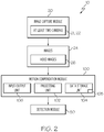
Fig. 2 is a block diagram of the aircraft-mounted object detection and collision avoidance system ofFig. 1 , and showing an apparatus constructed in accordance with an embodiment. -
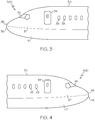
Fig. 3 is an image of the left side of the nose of the example aircraft ofFig. 1 from a camera mounted on a left aircraft wing. -
Fig. 4 is an image of the right side of the nose of the example aircraft ofFig. 1 from a camera mounted on a right aircraft wing. -
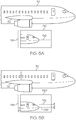
Figs. 5A, 5B , and5C are a series of images from the camera mounted on the right aircraft wing ofFig. 4 , and showing the effect of wing relative motion on the position of the nose of the aircraft. -
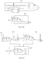
Fig. 6 is a compensated image showing the effect of image transformation that removes the effect of wing relative motion shown inFigs. 5A, 5B , and5C . -
Fig. 7 is a flow diagram depicting an object detection and collision avoidance method in which no motion compensation method is implemented. -
Fig. 8 is a flow diagram depicting the object detection and collision avoidance method ofFig. 7 in which a motion compensation method in accordance with an embodiment is implemented. -
Fig. 9 is a coordinates diagram of an example scenario showing (x, y, z) distance coordinates of an object relative to a camera mounted on a left aircraft wing and another camera mounted on a right aircraft wing. - The present application is directed to an apparatus and method of compensating for relative motion of at least two aircraft-mounted cameras. The specific apparatus, motion compensation methods, and the industry in which the apparatus and motion compensation methods are implemented may vary. It is to be understood that the disclosure below provides a number of embodiments or examples for implementing different features of various embodiments. Specific examples of components and arrangements are described to simplify the present disclosure. These are merely examples and are not intended to be limiting.
- By way of example, the disclosure below describes an apparatus and motion compensation methods for aircraft in compliance with Federal Aviation Administration (FAA) regulations. Specifications of FAA regulations are known and, therefore, will not be described.
- Referring to
Fig. 1 , an aircraft-mounted object detection and collision avoidance system, generally designated 10, embodying an apparatus in accordance with an example implementation, may be used in association with avehicle 12. Thevehicle 12 may be moving along a path (e.g., in the direction indicated by direction arrow 14). Anobject 16 may be moving along a path (e.g., in a direction indicated by arrow 18). Depending upon the relative positions and/or relative movements of thevehicle 12 and/or theobject 16, theobject 16 may impact with (e.g., strike) thevehicle 12. Those skilled in the art will appreciate that thevehicle 12 andobject 16 may not necessarily be shown to scale inFig. 1 . - In the example implementation illustrated in
Fig. 1 , thevehicle 12 may be any type ofaircraft 30. For example and without limitation, theaircraft 30 may be a fixed wing, a rotary wing, or a lighter than air aircraft. Theaircraft 30 may be manned or unmanned. As an example, theaircraft 30 may be a commercial passenger aircraft operated by an airline, a cargo aircraft operated by a private or public entity, a military aircraft operated by a military or other government organization, a personal aircraft operated by an individual, or any other type of aircraft operated by any other aircraft operator. As another example, theaircraft 30 may be an unmanned aerial vehicle (UAV) operated by a remote operator. Thus, those skilled in the art will appreciate that the vehicle 12 (e.g., aircraft 30) may be designed to perform any mission and may be operated by any operator of thevehicle 12. - The
object 16 may be any object that may potentially strike thevehicle 12. As an example, theobject 16 may be any moving airborne object moving along thepath 18 that may intersect thepath 14 of thevehicle 12. For example, as illustrated inFig. 1 , theobject 16 may be abird 34. As another example and without limitation, theobject 16 may be another aircraft, or any other airborne man-made or natural object. - Throughout the present disclosure, the terms "strike", "struck", "collision", "collide" and any similar or related terms may refer to the impact of the
vehicle 12 and theobject 16. For example, the phrase "an object striking or potentially striking a vehicle" may refer to a movingvehicle 12 impacting with a moving object 16 (e.g., an airborne object). - Referring to
Fig. 2 , thesystem 10 may include at least oneimage capture module 20. Theimage capture module 20 may be connected to the vehicle 12 (e.g., aircraft 30) shown inFig. 1 . Theimage capture module 20 includes at least twocameras cameras cameras cameras cameras - The two
cameras cameras cameras - For example, the two
cameras cameras cameras cameras - In an example implementation, the images 24 may be
video images 26. Thevideo images 26 may include a sequential series of digital video image frames taken rapidly over a period of time (e.g., 30 Hz). The images 24 provided by the twocameras more objects 16 and to identify one or more characteristics of theobject 16. - Referring back to
Fig. 1 , theimage capture module 20 may include a field ofview 40. For example, the twocameras view 40. For example, the twocameras vehicle 12 looking forwardly and having an unobstructed field of view 40 (e.g., the field ofview 40 not obstructed by the vehicle 12). The field ofview 40 may be defined by atarget area 15 in front of the vehicle 12 (e.g., aircraft 30) betweenlines 28 and 29 (e.g., in the direction ofmovement 14 of the vehicle 12). For example, thetarget area 15 may include a cone extending forward of thevehicle 12. The object 16 (e.g., the bird 34) may be within the field ofview 40. Therefore, the images 24 from the at least twocameras 22 may include images of theobject 16. - In an example implementation, the two
cameras cameras cameras system 10 to determine the distance of theobject 16 relative to thevehicle 12 using a stereo solution (e.g., stereo vision). - The two
cameras vehicle 12 at any suitable or appropriate location. For simplicity and purposes of description herein, onecamera 21 is mounted to the end of onewing 31 of theaircraft 30 and theother camera 22 is mounted to the end of theother wing 32 of theaircraft 30, as schematically shown inFig. 1 . Those skilled in the art will appreciate that the twocameras - The two
cameras image capture module 20 may be connected to thevehicle 12 at various positions and orientations. The twocameras cameras object 16 in the path of thevehicle 12 or crossing the path of the vehicle 12 (e.g., within the field of view 40). - Referring again to
Fig. 2 , thesystem 10 may include adetection module 50. Thedetection module 50 may be configured to receive the images 24 transmitted by theimage capture module 20. Thedetection module 50 may be configured to process the images 24 and determine the presence of theobject 16 and whether theobject 16 is likely to strike thevehicle 12. Thedetection module 50 may also be configured to identify and/or determine various characteristics of theobject 16 based on the images 24. Thedetection module 50 may also be configured to determine various characteristics of a potential strike. - However, before the
detection module 50 processes the images 24, the images 24 are processed by an apparatus including amotion compensation module 100 constructed in accordance with an embodiment. Themotion compensation module 100 includes aprocessing unit 102 that executes instructions stored in an internaldata storage unit 104, an external data storage unit (not shown), or a combination thereof. Theprocessing unit 102 may comprise any type of technology. For example, theprocessing unit 102 may comprise a dedicated-purpose electronic processor. Other types of processors and processing unit technologies are possible. The internaldata storage unit 104 may comprise any type of technology. For examples, the internaldata storage unit 104 may comprise random access memory (RAM), read only memory (ROM), solid state memory, or any combination thereof. Other types of memories and data storage unit technologies are possible. - The
motion compensation module 100 further includes a number of input/output (I/O)devices 106 that may comprise any type of technology. For example, the I/O devices 106 may comprise a keypad, a keyboard, a touch-sensitive display screen, a liquid crystal display (LCD) screen, a microphone, a speaker, or any combination thereof. Other types of I/O devices and technologies are possible. - The
motion compensation module 100 processes the images 24 to compensate for variations in distance and orientation (e.g., rotation) between the twocameras wings aircraft 30 due to flexing motion of at least one of thewings processing unit 102 executes instructions of amotion compensation program 105 stored in thedata storage unit 104 to compensate for the variations in the distance and orientation between the twocameras wings motion compensation module 100 is described hereinbelow. - Referring to
Fig. 3 , theimage 300 shows a number of different features of theaircraft 30 visible form a camera mounted on the left wing. The features of theimage 300 include passenger window features 33, aircraft door features 34, pilot window features 35, fuselage features 36, and aircraft livery features 37. These are only example features of theaircraft 30. Other types of features are possible. The features in theimage 300 produce non-trivial correlations for purpose of relative motion compensation. - Referring to
Fig. 4 , theimage 400 shows a number of different features of theaircraft 30 visible from a camera mounted on the right wing. The features of theimage 400 include passenger window features 43, aircraft door features 44, pilot window features 45, fuselage features 46, and aircraft livery features 47. These are only example features of theaircraft 30. Other types of features are possible. The features in theimage 400 produce non-trivial correlations for purpose of relative motion compensation. - It should be apparent that the
image 300 from thecamera 21 on theleft aircraft wing 31 and theimage 400 from thecamera 22 on theright aircraft wing 32 are similar. The twoimages motion compensation module 100 in the same way. For simplicity, image processing of theimage 400 from thecamera 22 on theright aircraft wing 32 will be described in detail. It is understood that the same image processing details apply to thecamera 21 on theleft aircraft wing 31. - Referring to
Fig. 5A , animage 510 from thecamera 22 mounted on theright aircraft wing 32 with no right-wing motion (e.g., a neutral wing condition or no flexing of the right wing 32) is illustrated. This is the reference image of the right side of the aircraft, and is the image that all in-flight images from the right wing camera are correlated with to determine motion. This image is captured at the time of stereo calibration of the two, or more, cameras being used in the stereo ranging process. In theimage 510, the tip of the nose of theaircraft 30 aligns parallel with an original horizontal reference line 512 (shown as a dashed line). Also, in theimage 510, the nose of theaircraft 30 aligns perpendicular with an original vertical reference line 514 (also shown as dashed line). - Referring to
Fig. 5B , animage 520 from thecamera 22 mounted on theright aircraft wing 32 with right-wing motion in the upward direction (as shown by arrow "A" inFig. 5B ) is illustrated. When theright wing 32 moves in the upward direction (i.e., one type of flexed wing condition), thecamera 22 captures a different image, which is shown as theimage 520 inFig. 5B . Theimage 520 shows the tip of the nose of theaircraft 30 and features of theaircraft 30 shifted downward (as shown by arrow "B" inFig. 5B ). In theimage 520, the tip of the nose of theaircraft 30 aligns with an offset horizontal reference line 516 (shown as a dashed line). This offsethorizontal reference line 516 is offset from the originalhorizontal reference line 512 by a distance of "d" shown inFig. 5B . The offset distance "d" depends upon a number of factors including the length of theright wing 32, for example. - Referring to
Fig. 5C , animage 530 from thecamera 22 mounted on theright aircraft wing 32 with right-wing motion in a counter-clockwise twist direction (as shown by offset angle "φ" inFig. 5C ) is illustrated. When theright wing 32 twists in the counter-clockwise direction (i.e., another type of flexed wing condition), thecamera 22 mounted on theright aircraft wing 32 captures a different image, which is shown as theimage 530 inFig. 5C . In theimage 530, the tip of the nose of theaircraft 30 pivots in a clockwise twist direction (as shown by offset angle "θ" in theimage 530 inFig. 5C ). The offset angle of "θ" in theimage 530 and the offset angle "φ" on theright wing 32 should be about the same. - It should be apparent that
Figs. 5A, 5B , and5C show a series of images captured by thecamera 22 mounted on theright aircraft wing 32, and the effects of wing relative motion on the captured images. Theimage 510 ofFig. 5A shows no wing motion, theimage 520 ofFig. 5B shows an upward wing motion, and theimage 530 ofFig. 5C shows a counter-clockwise twisting wing motion. Other motions are similarly determined. - Referring to
Fig. 6 , a compensatedimage 540 showing the effect of image transformation that removes the effect of wing relative motion ofFigs. 5B , and5C is illustrated. The compensatedimage 540 is the result of transforming theimage 520 ofFig. 5B and transforming theimage 530 ofFig. 5C . As shown inFig. 6 , the compensatedimage 540 shows the offset distance of "d" in the image 520 (Fig. 5B ) being reduced to zero, and shows the offset angle "θ" in the image 530 (Fig. 5C ) being reduced to zero. - Referring to
Fig. 7 , a flow diagram 700 depicts an object detection and collision avoidance method in which no motion compensation method is implemented. Inblock 730, theleft wing camera 21 continuously captures video frames of objects (e.g., birds in this example), and detects and segments the birds. Similarly, inblock 740, theright wing camera 22 continuously captures video frames of the objects, and detects and segments the birds. After the left andright wing cameras block 750. Then, inblock 760, stereoscopic disparities are measured. - Based upon the associated bird objects from
block 750 and the stereoscopic disparities of the bird objects as measured inblock 760, bird ranges and bird range rates are computed as shown inblock 770. The process then proceeds to block 780 in which bird collision metrics are computed. If a potential bird collision is determined based upon the bird collision metrics computer inblock 780, then an alarm is provided to an operator as shown inblock 790. - The following additional description and explanations are provided with reference to the flow diagram 700 of
Fig. 7 . Since the twocameras cameras aircraft 30 can then be used to predict the number of bird collisions before any future time T based on the following simple collision indicator formula:
- As an example calculation for the above formula, C(T) can be calculated every video frame from the two
cameras - Referring to
Fig. 8 , a flow diagram 800 depicts the object detection and collision avoidance method ofFig. 7 in which a motion compensation method in accordance with an embodiment is implemented. Inblock 810, a left nose template is correlated. Then, inblock 820, an image from theleft wing camera 21 is transformed based upon the correlated nose template ofblock 810 to eliminate the left wing motion (both up/down vertical motion and clockwise/counter-clockwise twist motion). Similarly, in block 812, a right nose template is correlated. Then, inblock 814, an image from theright wing camera 22 is transformed based upon the correlated nose template of block 812 to eliminate the right wing motion (both up/down vertical motion and clockwise/counter-clockwise twist motion). - The following additional description and explanations are provided with reference to the flow diagram 800 of
Fig. 8 . In order to associate bird objects between the twocameras cameras 21, 22), the wing motion that causes relative locations of cameras to change need to be compensated. An apparatus including themotion compensation module 100 is described herein. - The front part of the
aircraft 30 is visible from each camera (each sees one side) of the at least twocameras aircraft wings aircraft 30 changes. The change in apparent location of the nose of theaircraft 30 from thecamera 22 can be tracked easily by constructing the right nose template and correlating captured images 24 from thecamera 22 against the right nose template. The right nose template may comprise the capturedimage 510 shown inFig. 5A , for example. The right nose template may comprise a black and white or color template, for example.Fig. 5B shows what happens with respect to thecamera 22 on theright aircraft wing 32 with wing motion in an upward direction.Fig. 5C shows what happens with respect to thecamera 22 on theright aircraft wing 32 with wing motion in a counter-clockwise twist. - When captured nose images 24 from the
camera 22 are correlated, features of theaircraft 30, such as thefeatures Fig. 4 , are used in the correlation against the right nose template, as shown in block 812 inFig. 8 . The best features to correlate are those with large derivatives which all sum together to cause a correlation peak when the right nose template matches the current nose image. - The movement of the correlation peak determines the movement (displacement) in two dimensional pixel space. By adjusting the bird positions in pixels with the reverse of this displacement, their positions in pixel space in the
camera 22 has been adjusted for the relative motion of thecamera 22 due to the flexing movement of theright aircraft wing 32. This adjustment of the bird positions in pixel space is shown as the compensatedimage 540 inFig. 6 described hereinabove. - The above-described correlation assumes that lens distortion of the
camera 22 has been compensated for during a pre-calibration step. This calibration step allows the creation of a fixed function p( ) that maps pixel locations (x, y) to solid angle vectors (θ, φ), where θ is the angle in x-y space (the reference ground plane of the airplane) and φ is the elevation angle off of the reference ground plane of the airplane. This is denoted by the following function:
- The above function is defined during final installation of the object detection and
collision avoidance system 10 and updated at periodic calibration intervals. - Referring to
Fig. 9 , a coordinates diagram 900 of an example scenario showing (x, y, z) showing distance coordinates of the object 16 (i.e., thebird 34 in this example) relative to thecamera 21 mounted on theleft aircraft wing 31 and thecamera 22 mounted on theright aircraft wing 32. As shown inFig. 9 , it is assumed that the aircraft point of impact is at the center of the coordinates diagram 900 (i.e., at the (x, y, z) coordinates of (0, 0, 0). - As an example calculation of the above function (0, φ) = p(x, y), let / = (lx, ly , 0) be the
left camera 21 location (z is assumed to be zero) and r = (rx, ry, 0) be theright camera 22 location on the tips of thewings Fig. 9 , the following are the coordinates for l and r:

- Then, given a bird location in pixel space in each camera (xl, yl ) and (xr, yr ), their locations in physical space line along the lines formed by the angles (θ
l , φl ) = p(xl, yl ) and (θr, φr ) = p(xr,yr ) and points in space given by the camera locations. These two lines then are defined by the following one-dimensional parametric forms:

- where the a and b direction vectors are determined by spherical to Cartesian coordinate conversion (using p( )):


- s = an unknown variable
- t = an unknown variable
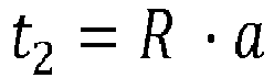
- The point of nearest intersection c can be calculated as follows:
- Let


- where m 2 is the dot product of the cross product of the direction vectors a and b
- R is defined as indicated above
- r is the direction vector for the right wing-mounted camera
- / is the direction vector for the left wing-mounted camera
- Also define the following variables:



- The point of nearest intersection c is equal to the following:

- An example scenario showing example calculations of the above-identified equations is described hereinbelow with reference to coordinates shown in
Fig. 9 . - First, it is assumed that the
aircraft 30 is centered at location (0, 0, 0), thebird 34 is at location (800, -200, 100), thecamera 21 on theleft aircraft wing 31 is at location (-40, -120, 0), and thecamera 22 on theright aircraft wing 32 is at location (-40, -120, 0). For example 1001x1001 pixel cameras with no lens distortion, the following angles for theleft camera 21 and theright camera 22 can be calculated as follows: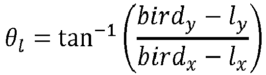



- Second, it is assumed that each of the
cameras bird 34 in the left andright cameras 

- Based upon the coordinates of the
bird 34 and thecameras Fig. 9 , the above-identified pixel locations for thebird 34 in the left andright cameras bird 34 would be found within the pixel space of the camera image for each frame. The angles θ l , θr , φl, Φr in degrees would be as follows:
- The normalized direction vectors a and b for the lines from the
cameras bird 34 would be as follows:

- Also, the calculations that compute the nearest point c between the two lines between the
cameras bird 34 would be as follows:



- Accordingly, the final resulting point (in this case the actual bird location) would be the midpoint c calculated as follows:

- It should be noted that q 1 and q 2 are both the same and equal to the correct answer because there was no motion error (due to flexing of the
aircraft wings 31, 32) introduced into the calculation as would be the case in a real system. - After the above-described wing motion error compensation is performed based upon
blocks left wing camera 21 and blocks 812 and 814 for theright wing camera 22, the process ofFig. 8 proceeds toblocks 830 and 840. Inblock 830 ofFig. 8 , theleft wing camera 21 continuously captures video frames of objects (e.g., birds in this example), and detects and segments the birds. Similarly, in block 840, the right wing camera continuously captures video frames of the birds, and detects and segments the birds. After the left andright wing cameras block 850. Then, inblock 860, stereoscopic disparities are measured. Based upon the associated bird objects fromblock 850 and the stereoscopic disparities of the bird objects as measured inblock 860, bird ranges and bird range rates are computed as shown inblock 870. - More specifically, the bird range (i.e., BR) from the
aircraft 30 can be calculated as norm of c or |c|, which gives the range of the bird to the center point (i.e., (0, 0, 0) between thewings aircraft 30. This can be calculated for each of the synchronized video frames of thecameras 
- Predicted bird strike events at any future time can be calculated using the above equation for BRRj.
- The process of
Fig. 8 then proceeds to block 880 in which bird collision metrics are computed. If a potential bird collision is determined based upon the bird collision metrics computed in block 880, then an alarm is provided to an operator as shown inblock 890. However, if no potential bird collision is determined based upon the bird collision metrics computed in block 880, then the process returns back to block 810 and block 812 to process the next image frame for each of the left andright wing cameras - Coded instructions to implement the motion compensation method may be stored in a mass storage device, in a volatile memory, in a non-volatile memory, and/or on a removable tangible computer readable storage medium such as a CD or DVD.
- The motion compensation method may be implemented using machine readable instructions that comprise a program for execution by a processor such as the
processing unit 102 shown in the examplemotion compensation module 100 discussed above in connection withFig. 1 . The program may be embodied in software stored on a tangible computer readable storage medium such as a CD-ROM, a floppy disk, a hard drive, a digital versatile disk (DVD), a Blu-ray disk, or a memory associated with theprocessing unit 102, but the entire program and/or parts thereof could alternatively be executed by a device other than theprocessing unit 102 and/or embodied in firmware or dedicated hardware. Many other methods of implementing the examplemotion compensation module 100 may alternatively be used. The order of execution of blocks may be changed, and/or some of blocks described with reference to the example flow diagram 800 shown inFig. 8 may be changed, eliminated, or combined. - As mentioned above, the example motion compensation method of
Fig. 8 may be implemented using coded instructions (e.g., computer and/or machine readable instructions) stored on a tangible computer readable storage medium such as a hard disk drive, a flash memory, a read-only memory (ROM), a compact disk (CD), a digital versatile disk (DVD), a cache, a random-access memory (RAM) and/or any other storage device or storage disk in which information is stored for any duration (e.g., for extended time periods, permanently, for brief instances, for temporarily buffering, and/or for caching of the information). As used herein, the term tangible computer readable storage medium is expressly defined to include any type of computer readable storage device and/or storage disk and to exclude propagating signals and to exclude transmission media. As used herein, "tangible computer readable storage medium" and "tangible machine readable storage medium" are used interchangeably. - Additionally or alternatively, the example motion compensation method of
Fig. 8 may be implemented using coded instructions (e.g., computer and/or machine readable instructions) stored on a non-transitory computer and/or machine readable medium such as a hard disk drive, a flash memory, a read-only memory, a compact disk, a digital versatile disk, a cache, a random-access memory and/or any other storage device or storage disk in which information is stored for any duration (e.g., for extended time periods, permanently, for brief instances, for temporarily buffering, and/or for caching of the information). As used herein, the term non-transitory computer readable medium is expressly defined to include any type of computer readable storage device and/or storage disk and to exclude propagating signals and to exclude transmission media. As used herein, when the phrase "at least" is used as the transition term in a preamble of a claim, it is open-ended in the same manner as the term "comprising" is open ended. - While an example manner of implementing the example aircraft-mounted object detection and
collision avoidance system 10 is illustrated inFig. 2 , one or more of the elements, processes and/or devices illustrated inFig. 2 may be combined, divided, re-arranged, omitted, eliminated and/or implemented in any other way. Further, the examplemotion compensation module 100 and/or, more generally, the example aircraft-mounted object detection andcollision avoidance system 10 ofFig. 2 may be implemented by hardware, software, firmware and/or any combination of hardware, software and/or firmware. Thus, for example, any of the examplemotion compensation module 100 and/or, more generally, the example aircraft-mounted object detection andcollision avoidance system 10 could be implemented by one or more analog or digital circuit(s), logic circuits, programmable processor(s), application specific integrated circuit(s) (ASIC(s)), programmable logic device(s) (PLD(s)) and/or field programmable logic device(s) (FPLD(s)). - When reading any of the apparatus or system claims of this patent to cover a purely software and/or firmware implementation, at least one of the example
motion compensation module 100 and/or, more generally, the example aircraft-mounted object detection andcollision avoidance system 10 is/are hereby expressly defined to include a tangible computer readable storage device or storage disk such as a memory, a digital versatile disk (DVD), a compact disk (CD), a Blu-ray disk, etc. storing the software and/or firmware. - The mounting of the two
cameras wings cameras 21, 22) for accurate distance measurement. However, as thewings cameras motion compensation module 100, the relative motion of thecameras - Also, the mounting of the two
cameras wings cameras motion compensation module 100 provides a real-time way to calculate the distance between the twocameras cameras aircraft 30 and an approaching object to be avoided. - Although the above description describes the object to be avoided by the
aircraft 30 is in the air, it is conceivable that the object to be avoided by the aircraft be an object that is not in the air, such as an object on a runway for example. - Also, although the above description describes the
image capture module 20 as having only two cameras, it is conceivable that more than two cameras be used. However, the use of more than two cameras would provide shorter baselines that lead to less accurate distance measurements. For example, a third camera (not shown) can be mounted on a portion of theaircraft 30. The processing unit 102 (Fig. 2 ) can be configured to execute instructions of themotion compensation program 105 to compensate for motions in the real-time distance between theleft camera 21 and the third camera, motions in the real-time distance between theright camera 22 and the third camera, or both. The detection module can be configured to calculate a distance between theaircraft 30 and theobject 16 based upon at least one of the calculated real-time distance between theleft camera 21 and theright camera 22, the calculated real-time distance between theleft camera 21 and the third camera, and the calculated real-time distance between theright camera 22 and the third camera. - Further, although the above-description describes an example apparatus and an example motion compensation method for aircraft in the aviation industry in accordance with FAA regulations, it is contemplated that apparatus and motion compensation methods may be implemented for any industry in accordance with the applicable industry standards.
- According to a first further aspect, there is provided a method of compensating for variations in distance between first and second wing-mounted cameras of an aircraft due to flexing of at least one aircraft wing, the method comprising:
- determining a first distance and orientation between the first wing-mounted camera and the second wing-mounted camera during a neutral wing condition of the aircraft;
- determining a second distance and orientation between the first wing-mounted camera and the second wing-mounted camera during a flexed wing condition of the aircraft; and
- processing the difference between the first and second distances and orientations to provide a real-time varying distance and orientation for use in providing a compensated distance and orientation between the first and second wing-mounted cameras.
- Optionally, processing the difference between the first and second distances and orientations includes correlating captured images from the first wing-mounted camera against a left nose template.
- Optionally, processing the difference between the first and second distances and orientations includes transforming the correlated images associated with the first wing-mounted camera to eliminate left wing motion.
- Optionally, processing the difference between the first and second distances and orientations includes correlating captured images from the second wing-mounted camera against a right nose template.
- Optionally, processing the difference between the first and second distances and orientations includes transforming the correlated images associated with the second wing-mounted camera to eliminate right wing motion.
- Optionally, processing the difference between the first and second distances and orientations includes (i) correlating captured images from the first wing-mounted camera against a left nose template, (ii) transforming the correlated images associated with the first wing-mounted camera to eliminate left wing motion, (iii) correlating captured images from the second wing-mounted camera against a right nose template, and (iv) transforming the correlated images associated with the second wing-mounted camera to eliminate right wing motion.
- Optionally, the method is performed by a computer having a memory executing one or more programs of instructions which are tangibly embodied in a program storage medium readable by the computer.
- According to a second further aspect, there is provided an aircraft-mounted object detection and collision avoidance system in which captured image data is correlated and transformed in accordance with the method of the first further aspect.
- Optionally, the aircraft-mounted object detection and collision avoidance system in which captured image data is correlated and transformed in accordance with the method of the second further aspect, wherein the captured image data is provided by a left wing-mounted camera of the aircraft and a right wing-mounted camera of the aircraft.
- According to a third further aspect, there is provided a method of processing image data captured by a left wing-mounted camera of an aircraft and a right wing-mounted camera of the aircraft to compensate for variations in distance between the cameras due to flexing of left and right aircraft wings, the method comprising:
- correlating captured images from the left wing-mounted camera against a left nose template associated with a left aircraft wing;
- transforming image data from at least one image frame captured by the left wing-mounted camera to eliminate motion associated with motion of the left aircraft wing;
- correlating captured images from the right wing-mounted camera against a right nose template associated with a right aircraft wing; and
- transforming image data from at least one image frame captured by the right wing-mounted camera to eliminate motion associated with motion of the right aircraft wing.
- According to a fourth further aspect, there is provided an aircraft-mounted object detection and collision avoidance system in which captured image data is correlated and transformed in accordance with the method of the third further aspect.
- Optionally, the captured image data is provided by a left wing-mounted camera of the aircraft and a right wing-mounted camera of the aircraft.
- Optionally, the method is performed by a computer having a memory executing one or more programs of instructions which are tangibly embodied in a program storage medium readable by the computer.
- According to a fifth further aspect, there is provided an apparatus for an aircraft-mounted object detection and collision avoidance system, the apparatus comprising:
- a first camera attached to one portion of the aircraft;
- a second camera attached to another portion of the aircraft, wherein the first and second cameras cooperate to captures images of an object in a flight path;
- a motion compensation module configured to calculate a real-time distance and orientation between the first camera and the second camera; and
- a detection module configured to calculate a distance and an orientation between the aircraft and the object based upon the calculated real-time distance and orientation between the first camera and the second camera.
- Optionally, each of the first and second cameras comprises a stereovision camera.
- Optionally, the motion compensation module includes a data storage unit in which a motion compensation program is stored and a processing unit configured to execute instructions of the motion compensation program to compensate for variations in the real-time distance and orientation between the first and second cameras.
- Optionally, the first camera is mounted on an aircraft wing, the second camera is mounted on an aircraft wing, and the processing unit is configured to execute instructions of the motion compensation program to compensate for motions in the real-time distance and orientation between the first and second cameras due to flexing of one or more aircraft wings.
- Optionally, the apparatus further comprises a third camera mounted on a portion of the aircraft, wherein the processing unit is configured to execute instructions of the motion compensation program to compensate for motions in the real-time distance and orientation between the first and third cameras, motions in the real-time distance and orientation between the second and third cameras, or both.
- Optionally, the detection module is configured to calculate a distance between the aircraft and the object based upon at least one of the calculated real-time distance and orientation between the first camera and the second camera, the calculated real-time distance and orientation between the first camera and the third camera, and the calculated real-time distance and orientation between the second camera and the third camera.
- Optionally, the flight path comprises an airway path in the air or a runway path on the ground.
- Although various embodiments of the disclosed apparatus and motion compensation methods have been shown and described, modifications may occur to those skilled in the art upon reading the specification. The present application includes such modifications and is limited only by the scope of the claims.
Claims (15)
- A method of compensating for variations in distance between first and second wing 31, 32-mounted cameras 21, 22 of an aircraft 30 due to flexing of at least one aircraft 30 wing 31, 32, the method comprising:determining a first distance and orientation between the first wing 31-mounted camera 21 22 and the second wing 32-mounted camera 21, 22 during a neutral wing 31, 32 condition of the aircraft 30;determining a second distance and orientation between the first wing 31-mounted camera 21, 22 and the second wing 32-mounted camera 21, 22 during a flexed wing 31, 32 condition of the aircraft 30; andprocessing the difference between the first and second distances and orientations to provide a real-time varying distance and orientation for use in providing a compensated distance and orientation between the first and second wing 31, 32-mounted cameras 21, 22.
- The method according to Claim 1 wherein processing the difference between the first and second distances and orientations includes correlating captured images 24 from the first wing 31-mounted camera 21, 22 against a left nose template.
- The method according to Claim 2 wherein processing the difference between the first and second distances and orientations includes transforming the correlated images 24 associated with the first wing 31-mounted camera 21, 22 to eliminate left wing 31, 32 motion.
- The method according to any preceding Claim, wherein processing the difference between the first and second distances and orientations includes correlating captured images 24 from the second wing 32-mounted camera 21, 22 against a right nose template.
- The method according to Claim 4 wherein processing the difference between the first and second distances and orientations includes transforming the correlated images 24 associated with the second wing 32-mounted camera 21, 22 to eliminate right wing 31, 32 motion.
- The method according to any preceding Claim, wherein the method is performed by a computer having a memory executing one or more programs of instructions which are tangibly embodied in a program storage medium readable by the computer.
- An aircraft 30-mounted object 16 detection and collision avoidance system 10 in which captured image data is correlated and transformed in accordance with the method of any preceding Claim.
- The aircraft 30-mounted object 16 detection and collision avoidance system 10 of claim 7, wherein the captured image data is provided by a left wing 31, 32-mounted camera 21, 22 of the aircraft 30 and a right wing 31, 32-mounted camera 21, 22 of the aircraft 30.
- An apparatus for an aircraft-mounted object 16 detection and collision avoidance system 10, the apparatus comprising:a first camera 21 22 attached to one portion of the aircraft 30;a second camera 21, 22 attached to another portion of the aircraft 30, wherein the first and second cameras 21, 22 cooperate to captures images 24 of an object 16 in a flight path 18;a motion compensation module 100 configured to calculate a real-time distance and orientation between the first camera 21, 22 and the second camera 21, 22; anda detection module 50 configured to calculate a distance and an orientation between the aircraft 30 and the object 16 based upon the calculated real-time distance and orientation between the first camera 21, 21 and the second camera 21, 22.
- The apparatus according to Claim 9 wherein each of the first and second cameras 21, 22 comprises a stereovision camera.
- The apparatus according to Claim 9 or Claim 10, wherein the motion compensation module 100 includes a data storage unit 104 in which a motion compensation program is stored and a processing unit 102 configured to execute instructions of the motion compensation program to compensate for variations in the real-time distance and orientation between the first and second cameras 21, 22.
- The apparatus according to Claim 11 wherein the first camera 21, 22 is mounted on an aircraft 30 wing 31, 32, the second camera 21, 22 is mounted on an aircraft 30 wing 31, 32, and the processing unit 102 is configured to execute instructions of the motion compensation program to compensate for motions in the real-time distance and orientation between the first and second cameras 21, 22 due to flexing of one or more aircraft 30 wings 31, 32.
- The apparatus according to Claim 12 further comprising a third camera 21, 22 mounted on a portion of the aircraft 30, wherein the processing unit 102 is configured to execute instructions of the motion compensation program to compensate for motions in the real-time distance and orientation between the first and third cameras 21, 22, motions in the real-time distance and orientation between the second and third cameras 21, 22, or both.
- The apparatus according to Claim 13 wherein the detection module 50 is configured to calculate a distance between the aircraft 30 and the object 16 based upon at least one of the calculated real-time distance and orientation between the first camera 21, 22 and the second camera 21, 22, the calculated real-time distance and orientation between the first camera21, 22 and the third camera21, 22, and the calculated real-time distance and orientation between the second camera21, 22 and the third camera 21, 22.
- The apparatus according to any one of Claims 9-14 wherein the flight path 18 comprises an airway path 18 in the air or a runway path 18 on the ground.
Applications Claiming Priority (1)
| Application Number | Priority Date | Filing Date | Title |
|---|---|---|---|
| US15/277,411 US20180091797A1 (en) | 2016-09-27 | 2016-09-27 | Apparatus and method of compensating for relative motion of at least two aircraft-mounted cameras |
Publications (2)
| Publication Number | Publication Date |
|---|---|
| EP3299299A1 true EP3299299A1 (en) | 2018-03-28 |
| EP3299299B1 EP3299299B1 (en) | 2021-03-24 |
Family
ID=60001681
Family Applications (1)
| Application Number | Title | Priority Date | Filing Date |
|---|---|---|---|
| EP17193259.3A Active EP3299299B1 (en) | 2016-09-27 | 2017-09-26 | Apparatus and method of compensating for relative motion of at least two aircraft-mounted cameras |
Country Status (5)
| Country | Link |
|---|---|
| US (2) | US20180091797A1 (en) |
| EP (1) | EP3299299B1 (en) |
| JP (1) | JP6951138B2 (en) |
| KR (1) | KR102372790B1 (en) |
| CN (1) | CN107867405B (en) |
Cited By (2)
| Publication number | Priority date | Publication date | Assignee | Title |
|---|---|---|---|---|
| CN110181509A (en) * | 2019-05-14 | 2019-08-30 | 浙江树人学院(浙江树人大学) | A kind of industrial robot motion control method based on error compensation |
| EP3779925A1 (en) * | 2019-08-14 | 2021-02-17 | The Boeing Company | Camera-based angle tracking of swarms for collision avoidance |
Families Citing this family (14)
| Publication number | Priority date | Publication date | Assignee | Title |
|---|---|---|---|---|
| JP6335237B2 (en) * | 2016-09-15 | 2018-05-30 | 株式会社Subaru | Stereo distance measuring device, stereo distance measuring method, and stereo distance measuring program |
| JP6463319B2 (en) * | 2016-10-19 | 2019-01-30 | 株式会社Subaru | Stereo distance measuring device, stereo distance measuring method, and stereo distance measuring program |
| US10515559B2 (en) | 2017-08-11 | 2019-12-24 | The Boeing Company | Automated detection and avoidance system |
| FR3070527B1 (en) * | 2017-08-31 | 2020-11-06 | Airbus Helicopters | METHOD AND DEVICE FOR AVOIDING AN OBJECT BY DETECTION OF ITS APPROACH TO AN AIRCRAFT |
| US10922986B2 (en) | 2018-07-18 | 2021-02-16 | Simmons Precision Products, Inc. | Taxi strike alert system |
| US10878709B2 (en) * | 2018-07-19 | 2020-12-29 | The Boeing Company | System, method, and computer readable medium for autonomous airport runway navigation |
| US11483540B2 (en) | 2018-08-22 | 2022-10-25 | I-Conic Vision Ab | Method and corresponding system for generating video-based 3-D models of a target such as a dynamic event |
| US11364992B2 (en) * | 2018-10-23 | 2022-06-21 | The Boeing Company | Aligning aircraft with runway centerline during takeoff |
| US11024187B2 (en) * | 2018-12-19 | 2021-06-01 | The Boeing Company | Aircraft positioning on a taxiway |
| US11022972B2 (en) * | 2019-07-31 | 2021-06-01 | Bell Textron Inc. | Navigation system with camera assist |
| JP7516057B2 (en) * | 2020-02-05 | 2024-07-16 | キヤノン株式会社 | Information processing device, information processing method, and program |
| CN111457897B (en) * | 2020-04-23 | 2024-02-23 | 中国科学院上海技术物理研究所 | A swing-sweep multi-view aerial oblique photography camera and imaging method |
| WO2022135632A1 (en) * | 2020-12-22 | 2022-06-30 | Sam - Dimension Ug (Haftungsbeschränkt) | Apparatus and method for area mapping |
| US12420951B2 (en) * | 2022-09-30 | 2025-09-23 | Toyota Motor Engineering & Manufacturing North America, Inc. | Calibration of aircraft mounted cameras |
Citations (6)
| Publication number | Priority date | Publication date | Assignee | Title |
|---|---|---|---|---|
| US5581250A (en) * | 1995-02-24 | 1996-12-03 | Khvilivitzky; Alexander | Visual collision avoidance system for unmanned aerial vehicles |
| EP1087626A2 (en) * | 1999-09-22 | 2001-03-28 | Fuji Jukogyo Kabushiki Kaisha | Distance correcting apparatus in a surrounding monitoring system |
| DE102008046545A1 (en) * | 2008-09-10 | 2009-05-14 | Daimler Ag | Method for calibrating assembly for monitoring environment of vehicle, involves detecting environment of vehicle according to multiple image detection units |
| DE102008024308A1 (en) * | 2008-05-20 | 2009-12-03 | Eads Deutschland Gmbh | Method for detecting non-cooperative air traffic on-board of aircraft, involves calculating distance or position of target on both blades of aircraft from angles by two sensors |
| US20110184647A1 (en) * | 2009-12-14 | 2011-07-28 | David Yoel | Airborne widefield airspace imaging and monitoring |
| US20150329217A1 (en) * | 2014-05-19 | 2015-11-19 | Honeywell International Inc. | Aircraft strike zone display |
Family Cites Families (31)
| Publication number | Priority date | Publication date | Assignee | Title |
|---|---|---|---|---|
| EP0425288B1 (en) * | 1989-10-26 | 1999-09-22 | Canon Kabushiki Kaisha | Movement detection apparatus |
| JP4172554B2 (en) * | 1998-03-12 | 2008-10-29 | 富士重工業株式会社 | Stereo camera adjustment device |
| US6597304B2 (en) * | 2001-07-27 | 2003-07-22 | Veridian Erim International, Inc. | System and method for coherent array aberration sensing |
| JP4328551B2 (en) * | 2003-03-05 | 2009-09-09 | 富士重工業株式会社 | Imaging posture control device |
| JP4493434B2 (en) * | 2004-07-28 | 2010-06-30 | オリンパス株式会社 | Image generation method and apparatus |
| US7747106B2 (en) * | 2005-06-13 | 2010-06-29 | Sarnoff Corporation | Method and system for filtering, registering, and matching 2.5D normal maps |
| KR100731979B1 (en) * | 2005-10-18 | 2007-06-25 | 전자부품연구원 | A computer-readable recording medium recording a method and apparatus for synthesizing an intermediate image using a mesh based on a multi-view forward camera structure and a program for realizing the function to implement the same |
| US8064643B2 (en) * | 2006-12-06 | 2011-11-22 | Mobileye Technologies Limited | Detecting and recognizing traffic signs |
| CN101419705B (en) * | 2007-10-24 | 2011-01-05 | 华为终端有限公司 | Video camera demarcating method and device |
| EP2071515A1 (en) * | 2007-12-11 | 2009-06-17 | Honda Research Institute Europe GmbH | Visually tracking an object in real world using 2D appearance and multicue depth estimations |
| IL188655A (en) * | 2008-01-08 | 2011-09-27 | Rafael Advanced Defense Sys | System and method for navigating a remote control vehicle past obstacles |
| GB2458927B (en) * | 2008-04-02 | 2012-11-14 | Eykona Technologies Ltd | 3D Imaging system |
| DE102009050368A1 (en) * | 2008-10-24 | 2010-05-27 | Magna Electronics Europe Gmbh & Co.Kg | Method for automatically calibrating a virtual camera |
| DE102010042956A1 (en) * | 2010-10-26 | 2012-04-26 | Airbus Operations Gmbh | Method and arrangement for determining a load on an aircraft structure |
| WO2013006067A1 (en) * | 2011-07-04 | 2013-01-10 | Streeter Lee Vincent | Motion compensation in range imaging |
| IL219923A (en) * | 2011-08-02 | 2016-09-29 | Boeing Co | Aircraft traffic separation system |
| US9091762B2 (en) * | 2011-10-27 | 2015-07-28 | Gulfstream Aerospace Corporation | Methods and systems for avoiding a collision between an aircraft on a ground surface and an obstacle |
| KR101966920B1 (en) * | 2012-07-10 | 2019-04-08 | 삼성전자주식회사 | Method and apparatus for estimating motion of image using disparity information of multi view image |
| US9047675B2 (en) * | 2012-08-13 | 2015-06-02 | The Boeing Company | Strike detection using video images |
| WO2014047465A2 (en) * | 2012-09-21 | 2014-03-27 | The Schepens Eye Research Institute, Inc. | Collision prediction |
| US9031311B2 (en) * | 2013-02-28 | 2015-05-12 | The Boeing Company | Identification of aircraft surface positions using camera images |
| US20150015698A1 (en) * | 2013-07-10 | 2015-01-15 | Gulfstream Aerospace Corporation | Methods and systems for optical aircraft detection |
| CN103400018B (en) * | 2013-07-12 | 2016-03-09 | 中国民用航空飞行校验中心 | The system and method for a kind of flight program check and checking |
| US10055013B2 (en) * | 2013-09-17 | 2018-08-21 | Amazon Technologies, Inc. | Dynamic object tracking for user interfaces |
| US20150106005A1 (en) * | 2013-10-14 | 2015-04-16 | Gulfstream Aerospace Corporation | Methods and systems for avoiding a collision between an aircraft on a ground surface and an obstacle |
| US9047771B1 (en) * | 2014-03-07 | 2015-06-02 | The Boeing Company | Systems and methods for ground collision avoidance |
| WO2015142919A1 (en) * | 2014-03-17 | 2015-09-24 | BARNES, Megan, D. | Airplane collision avoidance |
| FR3024127B1 (en) * | 2014-07-25 | 2016-08-26 | Airbus Operations Sas | AUTONOMOUS AUTOMATIC LANDING METHOD AND SYSTEM |
| US9954992B2 (en) * | 2014-11-27 | 2018-04-24 | Purdue Research Foundation | Mobile device enabled robotic system |
| US10215836B2 (en) * | 2016-03-07 | 2019-02-26 | Raytheon Company | Geolocation on a single platform having flexible portions |
| US10178378B2 (en) * | 2016-04-12 | 2019-01-08 | Microsoft Technology Licensing, Llc | Binocular image alignment for near-eye display |
-
2016
- 2016-09-27 US US15/277,411 patent/US20180091797A1/en not_active Abandoned
-
2017
- 2017-07-18 JP JP2017138868A patent/JP6951138B2/en active Active
- 2017-08-14 KR KR1020170102978A patent/KR102372790B1/en active Active
- 2017-08-16 CN CN201710703131.XA patent/CN107867405B/en active Active
- 2017-09-26 EP EP17193259.3A patent/EP3299299B1/en active Active
-
2020
- 2020-09-30 US US17/038,493 patent/US20210392317A1/en not_active Abandoned
Patent Citations (6)
| Publication number | Priority date | Publication date | Assignee | Title |
|---|---|---|---|---|
| US5581250A (en) * | 1995-02-24 | 1996-12-03 | Khvilivitzky; Alexander | Visual collision avoidance system for unmanned aerial vehicles |
| EP1087626A2 (en) * | 1999-09-22 | 2001-03-28 | Fuji Jukogyo Kabushiki Kaisha | Distance correcting apparatus in a surrounding monitoring system |
| DE102008024308A1 (en) * | 2008-05-20 | 2009-12-03 | Eads Deutschland Gmbh | Method for detecting non-cooperative air traffic on-board of aircraft, involves calculating distance or position of target on both blades of aircraft from angles by two sensors |
| DE102008046545A1 (en) * | 2008-09-10 | 2009-05-14 | Daimler Ag | Method for calibrating assembly for monitoring environment of vehicle, involves detecting environment of vehicle according to multiple image detection units |
| US20110184647A1 (en) * | 2009-12-14 | 2011-07-28 | David Yoel | Airborne widefield airspace imaging and monitoring |
| US20150329217A1 (en) * | 2014-05-19 | 2015-11-19 | Honeywell International Inc. | Aircraft strike zone display |
Cited By (3)
| Publication number | Priority date | Publication date | Assignee | Title |
|---|---|---|---|---|
| CN110181509A (en) * | 2019-05-14 | 2019-08-30 | 浙江树人学院(浙江树人大学) | A kind of industrial robot motion control method based on error compensation |
| EP3779925A1 (en) * | 2019-08-14 | 2021-02-17 | The Boeing Company | Camera-based angle tracking of swarms for collision avoidance |
| US11257386B1 (en) | 2019-08-14 | 2022-02-22 | The Boeing Company | Camera-based angle tracking of swarms for collision avoidance |
Also Published As
| Publication number | Publication date |
|---|---|
| KR102372790B1 (en) | 2022-03-18 |
| EP3299299B1 (en) | 2021-03-24 |
| JP2018095231A (en) | 2018-06-21 |
| KR20180034213A (en) | 2018-04-04 |
| US20210392317A1 (en) | 2021-12-16 |
| US20180091797A1 (en) | 2018-03-29 |
| JP6951138B2 (en) | 2021-10-20 |
| CN107867405B (en) | 2023-04-11 |
| CN107867405A (en) | 2018-04-03 |
Similar Documents
| Publication | Publication Date | Title |
|---|---|---|
| US20210392317A1 (en) | Aircraft with opposed wingtip-mounted cameras and method of operating the aircraft that compensate for relative motion of the opposed wingtip-mounted cameras | |
| CA2975139C (en) | Stereo camera system for collision avoidance during aircraft surface operations | |
| Lai et al. | Characterization of Sky‐region Morphological‐temporal Airborne Collision Detection | |
| EP3479356B1 (en) | System and method for identifying a camera pose of a forward facing camera in a vehicle | |
| EP3371619B1 (en) | Uav detection | |
| US9047675B2 (en) | Strike detection using video images | |
| CN108364304A (en) | A kind of system and method for the detection of monocular airborne target | |
| CN115291219A (en) | Method and device for realizing dynamic obstacle avoidance of unmanned aerial vehicle by using monocular camera and unmanned aerial vehicle | |
| US11082635B2 (en) | Systems and methods for video display | |
| CN109263637A (en) | A kind of method and device of prediction of collision | |
| CN105716625A (en) | Method and system for automatically detecting a misalignment during operation of a monitoring sensor of an aircraft | |
| CN111144415A (en) | Method for detecting micro pedestrian target | |
| US12436542B2 (en) | Anti-collision system for an aircraft and aircraft including the anti-collision system | |
| Damas et al. | A visual tracking system for UAV landing on ships | |
| US12080180B2 (en) | Anti-collision system and method for an aircraft and aircraft including the anti-collision system | |
| Nel | Post-processing of UAV-captured images for enhanced mapping by image stitching | |
| KR101957662B1 (en) | Apparatus for calculating target information, method thereof and flight control system comprising the same | |
| Yoo et al. | Saliency combined particle filtering for aircraft tracking | |
| Dudek et al. | Cloud detection system for UAV sense and avoid: challenges and findings in flight experiments | |
| Forlenza et al. | A hardware in the loop facility for testing multisensor sense and avoid systems | |
| Molloy et al. | HMM relative entropy rate concepts for vision-based aircraft manoeuvre detection | |
| Damas et al. | Ship, Guide My Landing! A Binocular Extended Kalman Filter for Maritime UAV Landing Operations | |
| Forlenza | Vision based strategies for implementing Sense and Avoid capabilities onboard Unmanned Aerial Systems | |
| May et al. | Simplified stereo-vision for automated control | |
| Witte et al. | Multisensor based generation of templates for object tracking in complex scenarios |
Legal Events
| Date | Code | Title | Description |
|---|---|---|---|
| PUAI | Public reference made under article 153(3) epc to a published international application that has entered the european phase |
Free format text: ORIGINAL CODE: 0009012 |
|
| STAA | Information on the status of an ep patent application or granted ep patent |
Free format text: STATUS: REQUEST FOR EXAMINATION WAS MADE |
|
| 17P | Request for examination filed |
Effective date: 20170926 |
|
| AK | Designated contracting states |
Kind code of ref document: A1 Designated state(s): AL AT BE BG CH CY CZ DE DK EE ES FI FR GB GR HR HU IE IS IT LI LT LU LV MC MK MT NL NO PL PT RO RS SE SI SK SM TR |
|
| AX | Request for extension of the european patent |
Extension state: BA ME |
|
| STAA | Information on the status of an ep patent application or granted ep patent |
Free format text: STATUS: EXAMINATION IS IN PROGRESS |
|
| 17Q | First examination report despatched |
Effective date: 20181218 |
|
| REG | Reference to a national code |
Ref country code: DE Ref legal event code: R079 Ref document number: 602017035114 Country of ref document: DE Free format text: PREVIOUS MAIN CLASS: B64D0047080000 Ipc: B64D0045080000 |
|
| GRAP | Despatch of communication of intention to grant a patent |
Free format text: ORIGINAL CODE: EPIDOSNIGR1 |
|
| STAA | Information on the status of an ep patent application or granted ep patent |
Free format text: STATUS: GRANT OF PATENT IS INTENDED |
|
| RIC1 | Information provided on ipc code assigned before grant |
Ipc: G06T 7/593 20170101ALN20200924BHEP Ipc: G06K 9/00 20060101ALN20200924BHEP Ipc: B64D 45/08 20060101AFI20200924BHEP Ipc: G08G 5/04 20060101ALI20200924BHEP Ipc: G06T 7/32 20170101ALN20200924BHEP Ipc: H04N 13/243 20180101ALN20200924BHEP Ipc: G08G 5/00 20060101ALN20200924BHEP |
|
| RIC1 | Information provided on ipc code assigned before grant |
Ipc: G06T 7/593 20170101ALN20200929BHEP Ipc: G08G 5/00 20060101ALN20200929BHEP Ipc: G08G 5/04 20060101ALI20200929BHEP Ipc: H04N 13/243 20180101ALN20200929BHEP Ipc: G06K 9/00 20060101ALN20200929BHEP Ipc: B64D 45/08 20060101AFI20200929BHEP Ipc: G06T 7/32 20170101ALN20200929BHEP |
|
| INTG | Intention to grant announced |
Effective date: 20201014 |
|
| GRAS | Grant fee paid |
Free format text: ORIGINAL CODE: EPIDOSNIGR3 |
|
| GRAA | (expected) grant |
Free format text: ORIGINAL CODE: 0009210 |
|
| STAA | Information on the status of an ep patent application or granted ep patent |
Free format text: STATUS: THE PATENT HAS BEEN GRANTED |
|
| AK | Designated contracting states |
Kind code of ref document: B1 Designated state(s): AL AT BE BG CH CY CZ DE DK EE ES FI FR GB GR HR HU IE IS IT LI LT LU LV MC MK MT NL NO PL PT RO RS SE SI SK SM TR |
|
| REG | Reference to a national code |
Ref country code: GB Ref legal event code: FG4D |
|
| REG | Reference to a national code |
Ref country code: CH Ref legal event code: EP |
|
| REG | Reference to a national code |
Ref country code: IE Ref legal event code: FG4D |
|
| REG | Reference to a national code |
Ref country code: AT Ref legal event code: REF Ref document number: 1374259 Country of ref document: AT Kind code of ref document: T Effective date: 20210415 Ref country code: DE Ref legal event code: R096 Ref document number: 602017035114 Country of ref document: DE |
|
| REG | Reference to a national code |
Ref country code: LT Ref legal event code: MG9D |
|
| PG25 | Lapsed in a contracting state [announced via postgrant information from national office to epo] |
Ref country code: NO Free format text: LAPSE BECAUSE OF FAILURE TO SUBMIT A TRANSLATION OF THE DESCRIPTION OR TO PAY THE FEE WITHIN THE PRESCRIBED TIME-LIMIT Effective date: 20210624 Ref country code: FI Free format text: LAPSE BECAUSE OF FAILURE TO SUBMIT A TRANSLATION OF THE DESCRIPTION OR TO PAY THE FEE WITHIN THE PRESCRIBED TIME-LIMIT Effective date: 20210324 Ref country code: GR Free format text: LAPSE BECAUSE OF FAILURE TO SUBMIT A TRANSLATION OF THE DESCRIPTION OR TO PAY THE FEE WITHIN THE PRESCRIBED TIME-LIMIT Effective date: 20210625 Ref country code: HR Free format text: LAPSE BECAUSE OF FAILURE TO SUBMIT A TRANSLATION OF THE DESCRIPTION OR TO PAY THE FEE WITHIN THE PRESCRIBED TIME-LIMIT Effective date: 20210324 Ref country code: BG Free format text: LAPSE BECAUSE OF FAILURE TO SUBMIT A TRANSLATION OF THE DESCRIPTION OR TO PAY THE FEE WITHIN THE PRESCRIBED TIME-LIMIT Effective date: 20210624 |
|
| PG25 | Lapsed in a contracting state [announced via postgrant information from national office to epo] |
Ref country code: LV Free format text: LAPSE BECAUSE OF FAILURE TO SUBMIT A TRANSLATION OF THE DESCRIPTION OR TO PAY THE FEE WITHIN THE PRESCRIBED TIME-LIMIT Effective date: 20210324 Ref country code: RS Free format text: LAPSE BECAUSE OF FAILURE TO SUBMIT A TRANSLATION OF THE DESCRIPTION OR TO PAY THE FEE WITHIN THE PRESCRIBED TIME-LIMIT Effective date: 20210324 Ref country code: SE Free format text: LAPSE BECAUSE OF FAILURE TO SUBMIT A TRANSLATION OF THE DESCRIPTION OR TO PAY THE FEE WITHIN THE PRESCRIBED TIME-LIMIT Effective date: 20210324 |
|
| REG | Reference to a national code |
Ref country code: NL Ref legal event code: MP Effective date: 20210324 |
|
| REG | Reference to a national code |
Ref country code: AT Ref legal event code: MK05 Ref document number: 1374259 Country of ref document: AT Kind code of ref document: T Effective date: 20210324 |
|
| PG25 | Lapsed in a contracting state [announced via postgrant information from national office to epo] |
Ref country code: NL Free format text: LAPSE BECAUSE OF FAILURE TO SUBMIT A TRANSLATION OF THE DESCRIPTION OR TO PAY THE FEE WITHIN THE PRESCRIBED TIME-LIMIT Effective date: 20210324 |
|
| PG25 | Lapsed in a contracting state [announced via postgrant information from national office to epo] |
Ref country code: EE Free format text: LAPSE BECAUSE OF FAILURE TO SUBMIT A TRANSLATION OF THE DESCRIPTION OR TO PAY THE FEE WITHIN THE PRESCRIBED TIME-LIMIT Effective date: 20210324 Ref country code: CZ Free format text: LAPSE BECAUSE OF FAILURE TO SUBMIT A TRANSLATION OF THE DESCRIPTION OR TO PAY THE FEE WITHIN THE PRESCRIBED TIME-LIMIT Effective date: 20210324 Ref country code: LT Free format text: LAPSE BECAUSE OF FAILURE TO SUBMIT A TRANSLATION OF THE DESCRIPTION OR TO PAY THE FEE WITHIN THE PRESCRIBED TIME-LIMIT Effective date: 20210324 Ref country code: AT Free format text: LAPSE BECAUSE OF FAILURE TO SUBMIT A TRANSLATION OF THE DESCRIPTION OR TO PAY THE FEE WITHIN THE PRESCRIBED TIME-LIMIT Effective date: 20210324 Ref country code: SM Free format text: LAPSE BECAUSE OF FAILURE TO SUBMIT A TRANSLATION OF THE DESCRIPTION OR TO PAY THE FEE WITHIN THE PRESCRIBED TIME-LIMIT Effective date: 20210324 |
|
| PG25 | Lapsed in a contracting state [announced via postgrant information from national office to epo] |
Ref country code: IS Free format text: LAPSE BECAUSE OF FAILURE TO SUBMIT A TRANSLATION OF THE DESCRIPTION OR TO PAY THE FEE WITHIN THE PRESCRIBED TIME-LIMIT Effective date: 20210724 Ref country code: PT Free format text: LAPSE BECAUSE OF FAILURE TO SUBMIT A TRANSLATION OF THE DESCRIPTION OR TO PAY THE FEE WITHIN THE PRESCRIBED TIME-LIMIT Effective date: 20210726 Ref country code: PL Free format text: LAPSE BECAUSE OF FAILURE TO SUBMIT A TRANSLATION OF THE DESCRIPTION OR TO PAY THE FEE WITHIN THE PRESCRIBED TIME-LIMIT Effective date: 20210324 Ref country code: RO Free format text: LAPSE BECAUSE OF FAILURE TO SUBMIT A TRANSLATION OF THE DESCRIPTION OR TO PAY THE FEE WITHIN THE PRESCRIBED TIME-LIMIT Effective date: 20210324 Ref country code: SK Free format text: LAPSE BECAUSE OF FAILURE TO SUBMIT A TRANSLATION OF THE DESCRIPTION OR TO PAY THE FEE WITHIN THE PRESCRIBED TIME-LIMIT Effective date: 20210324 |
|
| REG | Reference to a national code |
Ref country code: DE Ref legal event code: R097 Ref document number: 602017035114 Country of ref document: DE |
|
| PG25 | Lapsed in a contracting state [announced via postgrant information from national office to epo] |
Ref country code: DK Free format text: LAPSE BECAUSE OF FAILURE TO SUBMIT A TRANSLATION OF THE DESCRIPTION OR TO PAY THE FEE WITHIN THE PRESCRIBED TIME-LIMIT Effective date: 20210324 Ref country code: AL Free format text: LAPSE BECAUSE OF FAILURE TO SUBMIT A TRANSLATION OF THE DESCRIPTION OR TO PAY THE FEE WITHIN THE PRESCRIBED TIME-LIMIT Effective date: 20210324 Ref country code: ES Free format text: LAPSE BECAUSE OF FAILURE TO SUBMIT A TRANSLATION OF THE DESCRIPTION OR TO PAY THE FEE WITHIN THE PRESCRIBED TIME-LIMIT Effective date: 20210324 |
|
| PLBE | No opposition filed within time limit |
Free format text: ORIGINAL CODE: 0009261 |
|
| STAA | Information on the status of an ep patent application or granted ep patent |
Free format text: STATUS: NO OPPOSITION FILED WITHIN TIME LIMIT |
|
| PG25 | Lapsed in a contracting state [announced via postgrant information from national office to epo] |
Ref country code: SI Free format text: LAPSE BECAUSE OF FAILURE TO SUBMIT A TRANSLATION OF THE DESCRIPTION OR TO PAY THE FEE WITHIN THE PRESCRIBED TIME-LIMIT Effective date: 20210324 |
|
| 26N | No opposition filed |
Effective date: 20220104 |
|
| REG | Reference to a national code |
Ref country code: CH Ref legal event code: PL |
|
| REG | Reference to a national code |
Ref country code: BE Ref legal event code: MM Effective date: 20210930 |
|
| PG25 | Lapsed in a contracting state [announced via postgrant information from national office to epo] |
Ref country code: IS Free format text: LAPSE BECAUSE OF FAILURE TO SUBMIT A TRANSLATION OF THE DESCRIPTION OR TO PAY THE FEE WITHIN THE PRESCRIBED TIME-LIMIT Effective date: 20210724 Ref country code: MC Free format text: LAPSE BECAUSE OF FAILURE TO SUBMIT A TRANSLATION OF THE DESCRIPTION OR TO PAY THE FEE WITHIN THE PRESCRIBED TIME-LIMIT Effective date: 20210324 |
|
| PG25 | Lapsed in a contracting state [announced via postgrant information from national office to epo] |
Ref country code: LU Free format text: LAPSE BECAUSE OF NON-PAYMENT OF DUE FEES Effective date: 20210926 Ref country code: IE Free format text: LAPSE BECAUSE OF NON-PAYMENT OF DUE FEES Effective date: 20210926 Ref country code: BE Free format text: LAPSE BECAUSE OF NON-PAYMENT OF DUE FEES Effective date: 20210930 |
|
| PG25 | Lapsed in a contracting state [announced via postgrant information from national office to epo] |
Ref country code: LI Free format text: LAPSE BECAUSE OF NON-PAYMENT OF DUE FEES Effective date: 20210930 Ref country code: CH Free format text: LAPSE BECAUSE OF NON-PAYMENT OF DUE FEES Effective date: 20210930 |
|
| PG25 | Lapsed in a contracting state [announced via postgrant information from national office to epo] |
Ref country code: IT Free format text: LAPSE BECAUSE OF FAILURE TO SUBMIT A TRANSLATION OF THE DESCRIPTION OR TO PAY THE FEE WITHIN THE PRESCRIBED TIME-LIMIT Effective date: 20210324 |
|
| PG25 | Lapsed in a contracting state [announced via postgrant information from national office to epo] |
Ref country code: HU Free format text: LAPSE BECAUSE OF FAILURE TO SUBMIT A TRANSLATION OF THE DESCRIPTION OR TO PAY THE FEE WITHIN THE PRESCRIBED TIME-LIMIT; INVALID AB INITIO Effective date: 20170926 |
|
| P01 | Opt-out of the competence of the unified patent court (upc) registered |
Effective date: 20230516 |
|
| PG25 | Lapsed in a contracting state [announced via postgrant information from national office to epo] |
Ref country code: CY Free format text: LAPSE BECAUSE OF FAILURE TO SUBMIT A TRANSLATION OF THE DESCRIPTION OR TO PAY THE FEE WITHIN THE PRESCRIBED TIME-LIMIT Effective date: 20210324 |
|
| PG25 | Lapsed in a contracting state [announced via postgrant information from national office to epo] |
Ref country code: MK Free format text: LAPSE BECAUSE OF FAILURE TO SUBMIT A TRANSLATION OF THE DESCRIPTION OR TO PAY THE FEE WITHIN THE PRESCRIBED TIME-LIMIT Effective date: 20210324 |
|
| PG25 | Lapsed in a contracting state [announced via postgrant information from national office to epo] |
Ref country code: TR Free format text: LAPSE BECAUSE OF FAILURE TO SUBMIT A TRANSLATION OF THE DESCRIPTION OR TO PAY THE FEE WITHIN THE PRESCRIBED TIME-LIMIT Effective date: 20210324 |
|
| PG25 | Lapsed in a contracting state [announced via postgrant information from national office to epo] |
Ref country code: MT Free format text: LAPSE BECAUSE OF FAILURE TO SUBMIT A TRANSLATION OF THE DESCRIPTION OR TO PAY THE FEE WITHIN THE PRESCRIBED TIME-LIMIT Effective date: 20210324 |
|
| PGFP | Annual fee paid to national office [announced via postgrant information from national office to epo] |
Ref country code: DE Payment date: 20250929 Year of fee payment: 9 |
|
| PGFP | Annual fee paid to national office [announced via postgrant information from national office to epo] |
Ref country code: GB Payment date: 20250929 Year of fee payment: 9 |
|
| PGFP | Annual fee paid to national office [announced via postgrant information from national office to epo] |
Ref country code: FR Payment date: 20250925 Year of fee payment: 9 |