EP3299262A1 - Caisse de vehicule automobile a panier de rangement d'une roue de secours et pourvu d'un ecran de protection thermique - Google Patents
Caisse de vehicule automobile a panier de rangement d'une roue de secours et pourvu d'un ecran de protection thermique Download PDFInfo
- Publication number
- EP3299262A1 EP3299262A1 EP17187285.6A EP17187285A EP3299262A1 EP 3299262 A1 EP3299262 A1 EP 3299262A1 EP 17187285 A EP17187285 A EP 17187285A EP 3299262 A1 EP3299262 A1 EP 3299262A1
- Authority
- EP
- European Patent Office
- Prior art keywords
- spare wheel
- support piece
- thermal protection
- basket
- strands
- Prior art date
- Legal status (The legal status is an assumption and is not a legal conclusion. Google has not performed a legal analysis and makes no representation as to the accuracy of the status listed.)
- Granted
Links
Images


Classifications
-
- B—PERFORMING OPERATIONS; TRANSPORTING
- B62—LAND VEHICLES FOR TRAVELLING OTHERWISE THAN ON RAILS
- B62D—MOTOR VEHICLES; TRAILERS
- B62D43/00—Spare wheel stowing, holding, or mounting arrangements
- B62D43/02—Spare wheel stowing, holding, or mounting arrangements external to the vehicle body
- B62D43/04—Spare wheel stowing, holding, or mounting arrangements external to the vehicle body attached beneath the vehicle body
-
- B—PERFORMING OPERATIONS; TRANSPORTING
- B60—VEHICLES IN GENERAL
- B60K—ARRANGEMENT OR MOUNTING OF PROPULSION UNITS OR OF TRANSMISSIONS IN VEHICLES; ARRANGEMENT OR MOUNTING OF PLURAL DIVERSE PRIME-MOVERS IN VEHICLES; AUXILIARY DRIVES FOR VEHICLES; INSTRUMENTATION OR DASHBOARDS FOR VEHICLES; ARRANGEMENTS IN CONNECTION WITH COOLING, AIR INTAKE, GAS EXHAUST OR FUEL SUPPLY OF PROPULSION UNITS IN VEHICLES
- B60K13/00—Arrangement in connection with combustion air intake or gas exhaust of propulsion units
- B60K13/04—Arrangement in connection with combustion air intake or gas exhaust of propulsion units concerning exhaust
-
- B—PERFORMING OPERATIONS; TRANSPORTING
- B60—VEHICLES IN GENERAL
- B60R—VEHICLES, VEHICLE FITTINGS, OR VEHICLE PARTS, NOT OTHERWISE PROVIDED FOR
- B60R13/00—Elements for body-finishing, identifying, or decorating; Arrangements or adaptations for advertising purposes
- B60R13/08—Insulating elements, e.g. for sound insulation
- B60R13/0876—Insulating elements, e.g. for sound insulation for mounting around heat sources, e.g. exhaust pipes
Definitions
- the present invention relates to the field of the automobile and more particularly that of the baskets for housing a spare wheel under a motor vehicle.
- the body of a motor vehicle comprises in particular a rear floor under which is mounted tilting a storage basket of a spare wheel so as to allow the removal of the spare wheel and the establishment of a flat tire of the vehicle replaced by the spare wheel.
- the spare wheel basket is usually stowed by means of a hook device disposed under the floor of the vehicle and intended to grip a free end of the basket.
- the other end of the basket is connected under the rear floor of the vehicle by a hinge for pivoting the basket about a hinge axis transverse to the vehicle from a high stowage position to a low position giving access to the spare wheel.
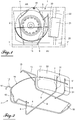
- the Figures 1 to 3 represent a basket according to the prior art for housing a spare wheel under the rear floor of the body of a motor vehicle.
- the reference 1 designates the rear floor of the body of the motor vehicle and under which is maintained a spare wheel 2 by means of a basket 3 for storing the spare wheel 2.
- the basket 3 consists of wires or rods of metal, for example steel, welded together and folded so as to form a first series of strands 4, 5 extending in a first plane and a second series of strands 6, 7, 8 substantially perpendicular to the first plane extending along the generatrices of a cylinder, two, 7, 8 strands of the second series, being located on the same side opposite the strand 6 of the same series with the two opposite strands 6, 7 connected to each other by a strand 9 secured by welding strands 4, 5 of the first series.
- the two strands 4, 5 of the first series have their ends located on the same side connected to a third series of strands 10, 11 substantially perpendicular to the first plane and strands 12, 13 substantially perpendicular to the strands 10, 11.
- the two strands 12, 13 respectively end with two hook-shaped ends 14, 15 anchored under the rear floor 1 of the vehicle to allow the basket 3 to pivot along an axis YY ' transverse to the vehicle of a high stowed position in which the spare wheel 2 is maintained under the rear floor 1 to a low position of withdrawal of the spare wheel.
- the strands 6, 7, 8, 10, 11 are connected together by a wire 16 curved in a circular arc and extending in a second plane substantially parallel to the first plane of the first series of strands 4, 5.
- the two strands 4, 5 of the first series are connected to each other opposite the hook-shaped ends 14, 15 by an end portion 18 approximately U-shaped that can be hooked to a hook 19 disposed under the floor of the vehicle so as to lock the basket 3 to the floor 1 to its position of maintenance of the spare wheel 2 under this floor.
- the spare wheel is supported by the strands 4, 5 of the first series and is held on these strands by the other strands 6, 7, 8, 10, 11 and the arcuate wire 16.
- the figures 1 and 3 partially represent an exhaust line of the combustion gases of the engine of the vehicle and comprising, integral under the floor 1, a pipe 20 partially shown and connected to the heat engine located in front AV of the vehicle, a silencer 21 and a pipe 22 Exhaust gas outlet rear AR of the vehicle.
- the exhaust muffler 21 is located near the spare wheel 2, it is necessary to protect the latter from the heat emitted by the exhaust muffler 21, whose temperature can rise to about 400 ° C.
- the tire of the spare wheel 2 can withstand without problem a temperature of about 65 ° C but must not withstand a temperature of not more than 100 ° C otherwise the rubber of the tire of the spare wheel 2 hardens . Beyond this temperature value of 100 ° C, the tire suppliers disclaim any liability for tire problems by rejecting this liability on the motor vehicle manufacturers.
- one solution is to provide a heat shield 30 interposed between the pipes 20, 22 and the muffler 21 of the exhaust line and which is fixed by welding to the basket 3.
- the thermal protection screen 30 which has the general shape of a substantially rectangular plate made of a steel sheet, optionally coated with an anticorrosive layer, is attached to the outside of the two strands 7 , 8 of the second series by welding points 31 following the contour of the arcuate wire 16 which is itself fixed by welding to the outside of the two strands 7, 8, the thermal protection screen 30 extending thus substantially perpendicular to the rear floor 1.
- the protective heat shield 30 thus secured to the basket 3 is not effective enough to protect the spare wheel 2 because it is made of sheet steel.
- the exhaust muffler 21 heats the thermal protection shield 30 by radiation and convection, thereby increasing the temperature between the exhaust muffler 21 and the thermal protection screen 30.
- thermal protection screen 30 heats the air between this screen and the spare wheel 2 whose temperature is still high enough to harden the tire of this wheel.
- the present invention aims to overcome the above drawback of the prior art by proposing a solution on the one hand avoiding to equip the diesel engine vehicles with a thermal protection screen of the spare wheel and on the other hand, for vehicles with gasoline engines, for installing, a thermal protection screen arrangement of the spare wheel which effectively protects the wheel from the heat of the muffler of the exhaust line.
- the invention relates to a body of a vehicle, such as a motor vehicle, comprising a rear floor, a storage basket of a spare wheel disposed under the rear floor, an exhaust line comprising in particular a silencer fixed under the rear floor, and a thermal protection screen interposed between the exhaust silencer and the spare wheel and which is characterized in that the screen thermal protection is removably fixed by means of fixing the storage basket of the spare wheel.
- the thermal protection screen is secured to a support piece removably attached by the fixing means to the storage basket of the spare wheel and outside of this basket with the thermal protection screen disposed in face of the silencer.
- the support piece is made of a rigid plastic material.
- the removable fastening means comprise clips made of material with the support piece.
- the storage basket of the spare wheel is made of metal son welded to each other and folded so as to form a first series of strands extending in a first plane and on which can rest the spare wheel, a second series strands substantially perpendicular to the first plane extending along generatrices of a cylinder, and a wire curved in an arc extending in a second plane parallel to the first plane being integral with at least two strands of the second series of strands and the clips of the support part elastically enclose at least one of the strands of the second series of strands and the wire curved in an arc.
- the support piece comprises on its outer face a hollow elongate recess in which is engaged the curved wire arcuate and whose convex portion protruding from the inner face of the support part is embedded in a hollow recessed elongate cavity. the inner face of the thermal protection screen.
- the thermal protection screen is made of aluminum and is fixed by crimping on the support part by means of lugs integral with the thermal protection screen.
- the thermal protection screen extends under the rear floor substantially perpendicular to the latter.
- the heat shield and the support piece each have the general shape of a rectangular plate.
- the invention also relates to a motor vehicle, which is characterized in that it comprises a box as defined above.
- the figure 4 shows that the storage basket 3 of the spare wheel under the rear floor of a vehicle, including automotive, is of a structure identical to that of the storage basket 3 of the spare wheel 2 described with reference to Figures 1 to 3 .
- the thermal protection screen 30 is removably attached to the storage basket 3 of the spare wheel by being interposed between the exhaust silencer 21 and the spare wheel 2 visible only to the figures 1 and 3 of the prior art.
- the thermal protection screen 30 is secured to a support member 40 removably attached by means or fasteners 50 to the storage basket 3 of the spare wheel so that the thermal protection screen 30 is arranged in front of the vehicle silencer and the support piece 40 is opposite the spare wheel.
- the support piece 40 is made of a rigid plastic material and the members for removably attaching this support piece to the storage basket 3 of the spare wheel comprise clips 50 coming from the material with the support piece 40 .
- the support piece 40 and the thermal shield 30 both have the general shape of a rectangular plate with the support piece 40 of a smaller width than that of the thermal shield 30 and a length substantially equal to that of this screen.
- the thermal protection screen 30 is advantageously made of aluminum and has integral at each of its ends, tabs 30a for fastening the screen 30 by crimping to the support piece 40.
- the screen 30 comprises one of its ends a continuous tab 30a along its width and folded over the corresponding outer end edge of the support piece 40 and two tabs 30a spaced from each other at its opposite end in the direction of the width of the screen 30 and folded over the outer end opposite edge of the support piece 40.
- the support piece 40 has on its outer or dorsal surface a hollow elongated fingerprint 40a extending substantially over the entire length of this piece and in which can be engaged the curved wire arcuate 16 of the storage basket 3 of the spare wheel.
- the convex portion of the recess 40a protruding from the inner face of the support piece 40 is embedded in a hollow elongated recess 30b of the inner face of the thermal shield 30 and extends substantially all the way along. of the latter.
- the impression 30b of the thermal protection screen 30 is of a shape conjugate with the convex impression projecting from the internal face of the support piece 40 so that the convex impression of the support piece 40 can fit into in the hollow cavity 30b of the thermal protection screen 30 before this screen is crimped onto the support part 40 by means of the tabs 30a of the thermal protection screen 30.
- the support piece 40 comprises two clips 50 located in a direction transverse to the length of the support piece 40 in the vicinity of one of the end edges of this piece.
- Each of these two clips 50 comprises two elastically deformable branches 51 projecting from the outer face of the support piece 40 and forming a clamp capable of elastically clamping the strand 8 of the storage basket 3 of the spare wheel.
- the support piece 40 comprises a third clip 50 located in the vicinity of the end edge of the support piece 40 opposite the one near which are the two other clips 50.
- the third clip 50 identical to the two previous ones, comprises two elastically deformable branches protruding from the outer face of the support piece 40 and capable of elastically clamping the curved wire arcuate 16 of the storage basket 3 of the spare wheel.
- the support piece 40 may comprise other clips 50, for example two other clips 50 situated in a direction transverse to the length of this piece and capable of elastically gripping the other strand 7 of the storage basket 3 of the spare wheel.
- the support piece 40 is removably attached to the strand (s) 7, 8 and to the metal wire 16 outside thereof, that is to say outside the basket 3 of storage of the spare wheel.
- this assembly When the unitary assembly formed by the thermal protection screen 30 and the support piece 40 is fixed by the clips 50 to the storage basket 3 of the spare wheel, this assembly has a curved portion along the curved contour of the wire. 16 of this basket with the support piece 40 turned towards the tire of the spare wheel of the vehicle.
- thermal protection screen described above of the invention can be added to the storage basket of the spare wheel or removed from it in an extremely simple and fast manner thanks to the fastening clips 50.
- the thermal protection screen 30 may be fixed in a mounting line on the storage basket of the spare wheel of a gasoline-powered vehicle. On the other hand, for vehicles with diesel engines, the thermal protection screen will not be mounted on the spare wheel storage basket.
- thermal protection screen being fixed to the storage basket of the spare wheel for gasoline-powered vehicles by means of the support part made of plastic material
- this screen can be made in aluminum, embossed or not, a material that has better thermal protection characteristics of a spare wheel vis-à-vis the muffler compared to a heat shield sheet steel.
- attachment of the thermal protection screen to the spare tire basket via the plastic support part is not only extremely simple but is also inexpensive.
- thermal protection screen could be removably attached directly to the storage basket of the spare wheel by any appropriate means.
Landscapes
- Engineering & Computer Science (AREA)
- Mechanical Engineering (AREA)
- Chemical & Material Sciences (AREA)
- Combustion & Propulsion (AREA)
- Transportation (AREA)
- Physics & Mathematics (AREA)
- Acoustics & Sound (AREA)
- Body Structure For Vehicles (AREA)
Abstract
Description
- La présente invention relève du domaine de l'automobile et plus particulièrement de celui des paniers pour loger une roue de secours sous un véhicule automobile.
- La caisse d'un véhicule automobile comprend notamment un plancher arrière sous lequel est monté basculant un panier de rangement d'une roue de secours de manière à permettre le retrait de la roue de secours et la mise en place d'une roue crevée du véhicule remplacée par la roue de secours.
- Le panier de la roue de secours est arrimé habituellement au moyen d'un dispositif à crochet disposé sous le plancher du véhicule et destiné à saisir une extrémité libre du panier. L'autre extrémité du panier est reliée sous le plancher arrière du véhicule par une articulation permettant de faire pivoter le panier autour d'un axe d'articulation transversal au véhicule d'une position haute d'arrimage vers une position basse donnant accès à la roue de secours.
- Les
figures 1 à 3 représentent un panier conforme à l'art antérieur permettant de loger une roue de secours sous le plancher arrière de la caisse d'un véhicule automobile. - Sur ces figures, la référence 1 désigne le plancher arrière de la caisse du véhicule automobile et sous lequel est maintenue une roue de secours 2 au moyen d'un panier 3 de rangement de la roue de secours 2.
- Le panier 3 est constitué de fils ou tiges métalliques, par exemple en acier, soudés les uns aux autres et pliés de façon à former une première série de brins 4, 5 s'étendant dans un premier plan et une seconde série de brins 6, 7, 8 sensiblement perpendiculaires au premier plan en s'étendant le long de génératrices d'un cylindre, deux, 7, 8 des brins de la seconde série, étant situés d'un même côté à l'opposé du brin 6 de cette même série avec les deux brins opposés 6, 7 reliés l'un à l'autre par un brin 9 solidaire par soudage des brins 4, 5 de la première série.
- Les deux brins 4, 5 de la première série ont leurs extrémités situées d'un même côté reliées à une troisième série de brins 10, 11 sensiblement perpendiculaires au premier plan et de brins 12, 13 sensiblement perpendiculaires aux brins 10, 11. Les deux brins 12, 13 se terminent respectivement par deux extrémités en forme de crochet 14, 15 ancrées sous le plancher arrière 1 du véhicule pour permettre au panier 3 de pivoter selon un axe Y-Y' transversal au véhicule d'une position haute arrimée dans laquelle la roue de secours 2 est maintenue sous le plancher arrière 1 vers une position basse de retrait de cette roue de secours.
- En outre, les brins 6, 7, 8, 10, 11 sont reliés ensemble par un fil métallique 16 courbé en arc de cercle et s'étendant dans un second plan sensiblement parallèle au premier plan de la première série de brins 4, 5.
- Les deux brins 4, 5 de la première série sont reliés l'un à l'autre à l'opposé des extrémités en forme de crochet 14, 15 par une partie d'extrémité 18 approximativement en forme de U pouvant être accrochée à un crochet 19 disposé sous le plancher du véhicule de manière à verrouiller le panier 3 au plancher 1 à sa position de maintien de la roue de secours 2 sous ce plancher. A cette position, la roue de secours est supportée par les brins 4, 5 de la première série et est maintenue sur ces brins par les autres brins 6, 7, 8, 10, 11 et le fil métallique arqué 16.
- Les
figures 1 et3 représentent en partie une ligne d'échappement des gaz de combustion du moteur thermique du véhicule et comprenant, solidaires sous le plancher 1, une tubulure 20 partiellement représentée et raccordée au moteur thermique situé en avant AV du véhicule, un silencieux 21 et une tubulure 22 de sortie des gaz d'échappement en arrière AR du véhicule. - Du fait que le silencieux d'échappement 21 soit situé à proximité de la roue de secours 2, il est nécessaire de protéger cette dernière de la chaleur émise par le silencieux d'échappement 21, dont la température peut s'élever jusqu'à environ 400°C.
- En effet, le pneumatique de la roue de secours 2 peut supporter sans problème une température d'environ 65°C mais ne doit pas supporter une température de pas plus de 100°C sinon la gomme du pneumatique de la roue de secours 2 se durcit. Au-delà de cette valeur de température de 100°C, les fournisseurs de pneumatiques se désengagent de toute responsabilité en cas de problème de pneumatique en rejetant cette responsabilité sur les constructeurs des véhicules automobiles.
- Pour résoudre ce problème de température élevée pouvant atteindre le pneumatique, une solution consiste à prévoir un écran thermique 30 interposé entre les tubulures 20, 22 et le silencieux 21 de la ligne d'échappement et qui est fixé par soudage au panier 3.
- Plus précisément, l'écran de protection thermique 30, qui présente la forme générale d'une plaque sensiblement rectangulaire réalisée en une tôle d'acier, le cas échéant revêtue d'une couche anticorrosion, est fixé à l'extérieur des deux brins 7, 8 de la seconde série par des points de soudure 31 en suivant le contour du fil métallique arqué 16 qui est lui-même fixé par soudage à l'extérieur des deux brins 7, 8, l'écran de protection thermique 30 s'étendant ainsi sensiblement perpendiculairement au plancher arrière 1.
- Cependant, l'écran thermique de protection 30 ainsi solidaire du panier 3 n'est pas suffisamment efficace pour protéger la roue de secours 2 car il est en tôle d'acier.
- En effet, le silencieux d'échappement 21 chauffe l'écran thermique de protection 30 par rayonnement et convection, augmentant alors la température entre le silencieux d'échappement 21 et l'écran de protection thermique 30.
- En outre, l'écran de protection thermique 30 réchauffe l'air entre cet écran et la roue de secours 2 dont la température est encore suffisamment élevée pour durcir le pneumatique de cette roue.
- Par ailleurs, il s'avère que les constructeurs de véhicules automobiles installent un panier de rangement d'une roue de secours avec un écran de protection thermique de cette roue non seulement sous des véhicules à moteurs à essence mais également sous des véhicules à moteurs diesels. Or, les lignes d'échappement des moteurs diesels ne comportent pas de silencieux mais uniquement une sourdine qui est très éloignée de la roue de secours. Dès lors, les véhicules à moteurs diesels n'ont pas besoin d'être équipés d'écrans de protection thermique des roues de secours.
- La présente invention a pour but de pallier l'inconvénient ci-dessus de l'art antérieur en proposant une solution d'une part évitant d'équiper les véhicules à moteurs diesels d'un écran de protection thermique de la roue de secours et d'autre part, pour les véhicules à moteurs à essence, permettant d'installer, un agencement d'écran de protection thermique de la roue de secours qui protège efficacement cette roue de la chaleur du silencieux de la ligne d'échappement.
- A cet effet, l'invention concerne une caisse d'un véhicule, tel qu'un véhicule automobile, comprenant un plancher arrière, un panier de rangement d'une roue de secours disposé sous le plancher arrière, une ligne d'échappement comprenant notamment un silencieux fixé sous le plancher arrière, et un écran de protection thermique interposé entre le silencieux d'échappement et la roue de secours et qui est caractérisée en ce que l'écran de protection thermique est amoviblement fixé par des moyens de fixation au panier de rangement de la roue de secours.
- De préférence, l'écran de protection thermique est solidaire d'une pièce de support amoviblement fixée par les moyens de fixation au panier de rangement de la roue de secours et à l'extérieur de ce panier avec l'écran de protection thermique disposé en face du silencieux.
- Avantageusement, la pièce de support est réalisée en une matière plastique rigide.
- De préférence, les moyens de fixation amovible comprennent des clips venant de matière avec la pièce de support.
- Le panier de rangement de la roue de secours est constitué de fils métalliques soudés les uns aux autres et pliés de façon à former une première série de brins s'étendant dans un premier plan et sur lesquels peut reposer la roue de secours, une seconde série de brins sensiblement perpendiculaires au premier plan en s'étendant le long de génératrices d'un cylindre, et un fil métallique courbé en arc de cercle s'étendant dans un second plan parallèle au premier plan en étant solidaire d'au moins deux brins de la seconde série de brins et les clips de la pièce de support enserrent élastiquement au moins l'un des brins de la seconde série de brins et le fil métallique courbé en arc de cercle.
- La pièce de support comprend à sa face externe une empreinte longiligne creuse dans laquelle est engagé le fil métallique courbé en arc de cercle et dont la partie convexe faisant saillie de la face interne de la pièce de support est encastrée dans une empreinte creuse longiligne conjuguée de la face interne de l'écran de protection thermique.
- De préférence, l'écran de protection thermique est réalisé en aluminium et est fixé par sertissage sur la pièce de support à l'aide de pattes solidaires de l'écran de protection thermique.
- L'écran de protection thermique s'étend sous le plancher arrière sensiblement perpendiculairement à ce dernier.
- L'écran de protection thermique et la pièce de support présentent chacun la forme générale d'une plaque rectangulaire.
- L'invention vise également un véhicule automobile, qui est caractérisé en ce qu'il comprend une caisse telle que définie précédemment.
- L'invention sera mieux comprise, et d'autres buts, caractéristiques, détails et avantages de celle-ci apparaîtront plus clairement dans la description explicative qui va suivre faite en référence aux dessins annexés donnés uniquement à titre d'exemple illustrant un mode de réalisation de l'invention et dans lesquels :
- La
figure 1 est une vue de dessous du plancher arrière d'un véhicule automobile pourvu d'un écran de protection thermique de l'art antérieur décrit précédemment ; - la
figure 2 est une vue en perspective du panier de rangement de la roue de secours de lafigure 1 et comportant l'écran thermique de protection ; - la
figure 3 est une vue partielle en perspective représentant l'écran de protection thermique de lafigure 1 situé en regard du silencieux de la ligne d'échappement du véhicule automobile ; - la
figure 4 est une vue en perspective du panier de rangement de la roue de secours de lafigure 2 et comportant un agencement d'écran de protection thermique conforme à l'invention ; - la
figure 5 est une vue en perspective de l'écran thermique de protection de l'invention, et - la
figure 6 est une vue en perspective d'une pièce de support permettant de fixer amoviblement l'écran de lafigure 5 au panier de rangement de la roue de secours. - La
figure 4 montre que le panier 3 de rangement de la roue de secours sous le plancher arrière d'un véhicule, notamment automobile, est d'une structure identique à celle du panier 3 de rangement de la roue de secours 2 décrit en référence auxfigures 1 à 3 . - Dans ces conditions, le panier 3 de rangement de la roue de secours de la
figure 4 ne sera pas à nouveau décrit dans sa structure. - Selon l'invention, l'écran de protection thermique 30 est amoviblement fixé au panier 3 de rangement de la roue de secours en étant interposé entre le silencieux d'échappement 21 et la roue de secours 2 visibles seulement aux
figures 1 et3 de l'art antérieur. - Plus précisément, l'écran de protection thermique 30 est solidaire d'une pièce de support 40 amoviblement fixée par des moyens ou organes de fixation 50 au panier 3 de rangement de la roue de secours de manière que l'écran de protection thermique 30 soit disposé en face du silencieux du véhicule et la pièce de support 40 soit en regard de la roue de secours.
- De préférence, la pièce de support 40 est réalisée en une matière plastique rigide et les organes permettant d'amoviblement fixer cette pièce de support au panier 3 de rangement de la roue de secours comprennent des clips 50 venant de matière avec la pièce de support 40.
- La pièce de support 40 et l'écran de protection thermique 30 présentent tous les deux la forme générale d'une plaque rectangulaire avec la pièce de support 40 d'une largeur plus faible que celle de l'écran de protection thermique 30 et d'une longueur sensiblement égale à celle de cet écran.
- L'écran de protection thermique 30 est avantageusement réalisé en aluminium et comporte solidaire de chacune de ses extrémités, des pattes 30a permettant de fixer jointivement par sertissage l'écran 30 sur la pièce de support 40. Par exemple, l'écran 30 comporte à l'une de ses extrémités une patte continue 30a suivant sa largeur et rabattue sur le bord d'extrémité externe correspondant de la pièce de support 40 et deux pattes 30a espacées l'une de l'autre à son extrémité opposée en direction de la largeur de l'écran 30 et rabattues sur le bord externe d'extrémité opposé de la pièce de support 40.
- La pièce de support 40 comporte à sa face externe ou dorsale une empreinte longiligne creuse 40a s'étendant sensiblement sur toute la longueur de cette pièce et dans laquelle peut être engagé le fil métallique courbé en arc de cercle 16 du panier 3 de rangement de la roue de secours. La partie convexe de l'empreinte 40a faisant saillie de la face interne de la pièce de support 40 s'encastre dans une empreinte longiligne creuse 30b de la face interne de l'écran de protection thermique 30 et qui s'étend sensiblement tout le long de cette dernière. L'empreinte 30b de l'écran de protection thermique 30 est de forme conjuguée à l'empreinte convexe faisant saillie de la face interne de la pièce de support 40 de manière que l'empreinte convexe de la pièce de support 40 puisse s'emboiter dans l'empreinte creuse 30b de l'écran de protection thermique 30 avant que cet écran soit fixé par sertissage sur la pièce de support 40 à l'aide des pattes 30a de l'écran de protection thermique 30.
- Comme le montre la
figure 4 , la pièce de support 40 comprend deux clips 50 situés sur une direction transversale à la longueur de la pièce de support 40 au voisinage de l'un des bords d'extrémité de cette pièce. - Chacun de ces deux clips 50 comprend deux branches élastiquement déformables 51 faisant saillie de la face externe de la pièce de support 40 et formant une pince susceptible d'enserrer élastiquement le brin 8 du panier 3 de rangement de la roue de secours.
- La pièce de support 40 comprend un troisième clip 50 situé au voisinage du bord d'extrémité de la pièce de support 40 à l'opposé de celui près duquel se trouvent les deux autres clips 50. Le troisième clip 50, identique aux deux précédents, comprend deux branches élastiquement déformables faisant saillie de la face externe de la pièce de support 40 et susceptibles d'enserrer élastiquement le fil métallique courbé en arc de cercle 16 du panier 3 de rangement de la roue de secours.
- Bien entendu, la pièce de support 40 peut comporter d'autres clips 50, par exemple deux autres clips 50 situés sur une direction transversale à la longueur de cette pièce et susceptible d'enserrer élastiquement l'autre brin 7 du panier 3 de rangement de la roue de secours.
- Ainsi, la pièce de support 40 est amoviblement fixée au(x) brin(s) 7, 8 et au fil métallique 16 à l'extérieur de ceux-ci, c'est-à-dire à l'extérieur du panier 3 de rangement de la roue de secours.
- Lorsque l'ensemble unitaire constitué par l'écran de protection thermique 30 et la pièce de support 40 est fixé par les clips 50 au panier 3 de rangement de la roue de secours, cet ensemble présente une partie incurvée suivant le contour courbé du fil métallique 16 de ce panier avec la pièce de support 40 tournée vers le pneumatique de la roue de secours du véhicule.
- Ainsi, l'écran de protection thermique ci-dessus décrit de l'invention peut être ajouté au panier de rangement de la roue de secours ou retiré de celui-ci d'une manière extrêmement simple et rapide grâce aux clips de fixation 50.
- L'écran de protection thermique 30 pourra être fixé en ligne de montage sur le panier de rangement de la roue de secours d'un véhicule à moteur à essence. Par contre, pour les véhicules à moteurs diesels, l'écran de protection thermique ne sera pas monté sur le panier de rangement de la roue de secours.
- Il est par ailleurs à noter que l'écran de protection thermique étant fixé au panier de rangement de la roue de secours pour les véhicules à moteurs à essence par l'intermédiaire de la pièce de support en matériau plastique, cet écran peut être réalisé en aluminium, gaufré ou non, matériau qui présente de meilleures caractéristiques de protection thermique d'une roue de secours vis-à-vis du silencieux comparativement à un écran de protection thermique en tôle d'acier. En outre, la fixation de l'écran de protection thermique au panier de la roue de secours par l'intermédiaire de la pièce de support en matière plastique est non seulement extrêmement simple mais est également peu coûteuse.
- D'autres variantes de réalisations peuvent être apportées sans sortir du cadre de l'invention. Ainsi, bien que cela ne soit pas le mode de réalisation préféré, il est possible d'envisager la fixation de la pièce de support de l'écran de protection thermique au panier de rangement de la roue de secours par l'intermédiaire d'un assemblage à vis de fixation enserrant les brins métalliques et/ou le fil métallique courbé du panier. Enfin, l'écran de protection thermique pourrait être amoviblement fixé directement au panier de rangement de la roue de secours par tout moyen approprié.
Claims (10)
- Caisse d'un véhicule, tel qu'un véhicule automobile, comprenant un plancher arrière (1), un panier (3) de rangement d'une roue de secours (2) disposé sous le plancher arrière (1), une ligne d'échappement comprenant notamment un silencieux (21) fixé sous le plancher arrière (1), et un écran de protection thermique (30) interposé entre le silencieux d'échappement (21) et la roue de secours (2), caractérisée en ce que l'écran de protection thermique (30) est amoviblement fixé par des moyens de fixation (50) au panier (3) de rangement de la roue de secours (2).
- Caisse selon la revendication 1, caractérisée en ce que l'écran de protection thermique (30) est solidaire d'une pièce de support (40) amoviblement fixée par les moyens de fixation (50) au panier (3) de rangement de la roue de secours (2) et à l'extérieur de ce panier avec l'écran de protection thermique (30) disposé en face du silencieux (21).
- Caisse selon la revendication 2, caractérisée en ce que la pièce de support (40) est réalisée en une matière plastique rigide.
- Caisse selon la revendication 3, caractérisée en ce que les moyens de fixation amovible comprennent des clips (50) venant de matière avec la pièce de support.
- Caisse selon la revendication 4, caractérisée en ce que le panier (3) de rangement de la roue de secours (2) est constitué de fils métalliques soudés les uns aux autres et pliés de façon à former une première série de brins (4,5) s'étendant dans un premier plan et sur lesquels peut reposer la roue de secours (2), une seconde série de brins (7,8) sensiblement perpendiculaires au premier plan en s'étendant le long de génératrices d'un cylindre, et un fil métallique courbé en arc de cercle (16) s'étendant dans un second plan parallèle au premier plan en étant solidaire d'au moins deux brins (7,8) de la seconde série de brins et en ce que les clips (50) de la pièce de support (40) enserrent élastiquement au moins l'un (7) des brins (7,8) de la seconde série de brins et le fil métallique courbé en arc de cercle (16).
- Caisse selon la revendication 5, caractérisée en ce que la pièce de support (40) comprend à sa face externe une empreinte longiligne creuse (40a) dans laquelle est engagé le fil métallique courbé en arc de cercle (16) et dont la partie convexe faisant saillie de la face interne de la pièce de support (40) est encastrée dans une empreinte creuse longiligne conjuguée (30b) de la face interne de l'écran de protection thermique (30).
- Caisse selon l'une des revendications 2 à 6, caractérisée en ce que l'écran de protection thermique (30) est réalisé en aluminium et est fixé par sertissage sur la pièce de support (40) à l'aide de pattes (30a) solidaires de l'écran de protection thermique (30).
- Caisse selon l'une des revendications 1 à 7, caractérisée en ce que l'écran de protection thermique (30) s'étend sous le plancher arrière (1) sensiblement perpendiculairement à ce dernier.
- Caisse selon l'une des revendications 2 à 8, caractérisée en ce que l'écran de protection thermique (30) et la pièce de support (40) présentent chacun la forme générale d'une plaque rectangulaire.
- Véhicule automobile, caractérisé en ce qu'il comprend une caisse selon l'une quelconque des revendications 1 à 9.
Applications Claiming Priority (1)
| Application Number | Priority Date | Filing Date | Title |
|---|---|---|---|
| FR1659113A FR3056549B1 (fr) | 2016-09-27 | 2016-09-27 | Caisse de vehicule automobile a panier de rangement d'une roue de secours et pourvu d'un ecran de protection thermique |
Publications (2)
| Publication Number | Publication Date |
|---|---|
| EP3299262A1 true EP3299262A1 (fr) | 2018-03-28 |
| EP3299262B1 EP3299262B1 (fr) | 2019-07-17 |
Family
ID=57539436
Family Applications (1)
| Application Number | Title | Priority Date | Filing Date |
|---|---|---|---|
| EP17187285.6A Active EP3299262B1 (fr) | 2016-09-27 | 2017-08-22 | Caisse de vehicule automobile a panier de rangement d'une roue de secours et pourvu d'un ecran de protection thermique |
Country Status (3)
| Country | Link |
|---|---|
| EP (1) | EP3299262B1 (fr) |
| ES (1) | ES2737863T3 (fr) |
| FR (1) | FR3056549B1 (fr) |
Cited By (1)
| Publication number | Priority date | Publication date | Assignee | Title |
|---|---|---|---|---|
| FR3159115A1 (fr) * | 2024-02-08 | 2025-08-15 | Stellantis Auto Sas | Dispositif de protection thermique. |
Citations (3)
| Publication number | Priority date | Publication date | Assignee | Title |
|---|---|---|---|---|
| EP0751044A1 (fr) * | 1995-06-27 | 1997-01-02 | TBA Composites Inc | Ecran thermique laminé |
| FR2924671A3 (fr) * | 2007-12-05 | 2009-06-12 | Renault Sas | Panier de roue de secours de vehicule automobile |
| FR3021288A1 (fr) * | 2014-05-20 | 2015-11-27 | Peugeot Citroen Automobiles Sa | Panier de rangement pour roue de secours de vehicule automobile |
-
2016
- 2016-09-27 FR FR1659113A patent/FR3056549B1/fr not_active Expired - Fee Related
-
2017
- 2017-08-22 ES ES17187285T patent/ES2737863T3/es active Active
- 2017-08-22 EP EP17187285.6A patent/EP3299262B1/fr active Active
Patent Citations (3)
| Publication number | Priority date | Publication date | Assignee | Title |
|---|---|---|---|---|
| EP0751044A1 (fr) * | 1995-06-27 | 1997-01-02 | TBA Composites Inc | Ecran thermique laminé |
| FR2924671A3 (fr) * | 2007-12-05 | 2009-06-12 | Renault Sas | Panier de roue de secours de vehicule automobile |
| FR3021288A1 (fr) * | 2014-05-20 | 2015-11-27 | Peugeot Citroen Automobiles Sa | Panier de rangement pour roue de secours de vehicule automobile |
Cited By (1)
| Publication number | Priority date | Publication date | Assignee | Title |
|---|---|---|---|---|
| FR3159115A1 (fr) * | 2024-02-08 | 2025-08-15 | Stellantis Auto Sas | Dispositif de protection thermique. |
Also Published As
| Publication number | Publication date |
|---|---|
| ES2737863T3 (es) | 2020-01-16 |
| FR3056549B1 (fr) | 2018-10-12 |
| EP3299262B1 (fr) | 2019-07-17 |
| FR3056549A1 (fr) | 2018-03-30 |
Similar Documents
| Publication | Publication Date | Title |
|---|---|---|
| FR2650235A1 (fr) | Deflecteur d'air mobile pour balai d'essuie-glace, notamment de vehicules automobiles | |
| CA2805401A1 (fr) | Adaptateur d'essuie-glace a contacts electriques | |
| EP3299262B1 (fr) | Caisse de vehicule automobile a panier de rangement d'une roue de secours et pourvu d'un ecran de protection thermique | |
| FR2914267A1 (fr) | Vehicule automobile comportant une cloison aeraulique | |
| EP2662273B1 (fr) | Potence de cycle à chape de serrage | |
| FR3056548A1 (fr) | Caisse de vehicule automobile a panier de rangement d'une roue de secours et pourvu d'un double ecran de protection thermique | |
| FR3120579A1 (fr) | Support d’un chargeur de batterie électrique d’un véhicule automobile | |
| EP2342447B1 (fr) | Vanne egr comportant une tole de support | |
| FR3052605A1 (fr) | Collier de maintien d’un faisceau electrique | |
| FR3085883A1 (fr) | Roue de vehicule comportant un insert et insert correspondant | |
| EP1882881A1 (fr) | Dispositif d'éclairage et/ou de signalisation multifonctions à protection thermique pour véhicule | |
| FR2949429A1 (fr) | Manchon de protection pour vehicule en particulier pour vehicule de type motocyclette | |
| FR3145130A1 (fr) | Pare-chocs pour véhicule automobile avec bloc d’attache de connecteurs électrique | |
| WO2021260309A1 (fr) | Capot de support d'alarme | |
| FR2969108A1 (fr) | Dispositif de maintien pour module d'echange de chaleur de vehicule automobile, et module d'echange de chaleur correspondant | |
| WO2016038265A1 (fr) | Véhicule automobile a ligne d'échappement courte et écran de protection thermique du réservoir de carburant de ce véhicule | |
| WO2009022082A2 (fr) | Agencement de fixation de deux elements de carrosserie adjacents | |
| FR3151884A1 (fr) | Agencement pour un système d’échappement de véhicule automobile | |
| FR2951410A1 (fr) | Agencement d'un groupe moto ventilateur et d'un radiateur | |
| FR2708242A1 (fr) | Dispositif d'essuie-glace à articulation d'éléments. | |
| EP1724124A1 (fr) | Bague de fixation d'un enjoliveur sur une roue et procede de montage associe | |
| EP4501680A1 (fr) | Carénage comprenant un support d'isolation thermique | |
| EP1319532B1 (fr) | Agencement pour la fixation sur un longeron creux d'un organe d'attelage à un élément de remorquage, ou d'arrimage, d'un véhicule automobile | |
| WO2017060580A1 (fr) | Ensemble pour châssis de vehicule automobile | |
| FR3064227A1 (fr) | Piece d’habillage de carrosserie de vehicule |
Legal Events
| Date | Code | Title | Description |
|---|---|---|---|
| PUAI | Public reference made under article 153(3) epc to a published international application that has entered the european phase |
Free format text: ORIGINAL CODE: 0009012 |
|
| STAA | Information on the status of an ep patent application or granted ep patent |
Free format text: STATUS: THE APPLICATION HAS BEEN PUBLISHED |
|
| AK | Designated contracting states |
Kind code of ref document: A1 Designated state(s): AL AT BE BG CH CY CZ DE DK EE ES FI FR GB GR HR HU IE IS IT LI LT LU LV MC MK MT NL NO PL PT RO RS SE SI SK SM TR |
|
| AX | Request for extension of the european patent |
Extension state: BA ME |
|
| STAA | Information on the status of an ep patent application or granted ep patent |
Free format text: STATUS: REQUEST FOR EXAMINATION WAS MADE |
|
| 17P | Request for examination filed |
Effective date: 20180820 |
|
| RBV | Designated contracting states (corrected) |
Designated state(s): AL AT BE BG CH CY CZ DE DK EE ES FI FR GB GR HR HU IE IS IT LI LT LU LV MC MK MT NL NO PL PT RO RS SE SI SK SM TR |
|
| GRAP | Despatch of communication of intention to grant a patent |
Free format text: ORIGINAL CODE: EPIDOSNIGR1 |
|
| RIC1 | Information provided on ipc code assigned before grant |
Ipc: B60R 13/08 20060101ALI20190109BHEP Ipc: B60K 13/04 20060101ALI20190109BHEP Ipc: B62D 43/04 20060101AFI20190109BHEP |
|
| STAA | Information on the status of an ep patent application or granted ep patent |
Free format text: STATUS: GRANT OF PATENT IS INTENDED |
|
| INTG | Intention to grant announced |
Effective date: 20190214 |
|
| GRAS | Grant fee paid |
Free format text: ORIGINAL CODE: EPIDOSNIGR3 |
|
| GRAA | (expected) grant |
Free format text: ORIGINAL CODE: 0009210 |
|
| STAA | Information on the status of an ep patent application or granted ep patent |
Free format text: STATUS: THE PATENT HAS BEEN GRANTED |
|
| AK | Designated contracting states |
Kind code of ref document: B1 Designated state(s): AL AT BE BG CH CY CZ DE DK EE ES FI FR GB GR HR HU IE IS IT LI LT LU LV MC MK MT NL NO PL PT RO RS SE SI SK SM TR |
|
| REG | Reference to a national code |
Ref country code: GB Ref legal event code: FG4D Free format text: NOT ENGLISH |
|
| REG | Reference to a national code |
Ref country code: CH Ref legal event code: EP |
|
| REG | Reference to a national code |
Ref country code: IE Ref legal event code: FG4D Free format text: LANGUAGE OF EP DOCUMENT: FRENCH |
|
| REG | Reference to a national code |
Ref country code: DE Ref legal event code: R096 Ref document number: 602017005316 Country of ref document: DE |
|
| REG | Reference to a national code |
Ref country code: AT Ref legal event code: REF Ref document number: 1155602 Country of ref document: AT Kind code of ref document: T Effective date: 20190815 |
|
| REG | Reference to a national code |
Ref country code: NL Ref legal event code: MP Effective date: 20190717 |
|
| REG | Reference to a national code |
Ref country code: LT Ref legal event code: MG4D |
|
| REG | Reference to a national code |
Ref country code: AT Ref legal event code: MK05 Ref document number: 1155602 Country of ref document: AT Kind code of ref document: T Effective date: 20190717 |
|
| REG | Reference to a national code |
Ref country code: ES Ref legal event code: FG2A Ref document number: 2737863 Country of ref document: ES Kind code of ref document: T3 Effective date: 20200116 |
|
| REG | Reference to a national code |
Ref country code: DE Ref legal event code: R084 Ref document number: 602017005316 Country of ref document: DE |
|
| PG25 | Lapsed in a contracting state [announced via postgrant information from national office to epo] |
Ref country code: FI Free format text: LAPSE BECAUSE OF FAILURE TO SUBMIT A TRANSLATION OF THE DESCRIPTION OR TO PAY THE FEE WITHIN THE PRESCRIBED TIME-LIMIT Effective date: 20190717 Ref country code: NO Free format text: LAPSE BECAUSE OF FAILURE TO SUBMIT A TRANSLATION OF THE DESCRIPTION OR TO PAY THE FEE WITHIN THE PRESCRIBED TIME-LIMIT Effective date: 20191017 Ref country code: SE Free format text: LAPSE BECAUSE OF FAILURE TO SUBMIT A TRANSLATION OF THE DESCRIPTION OR TO PAY THE FEE WITHIN THE PRESCRIBED TIME-LIMIT Effective date: 20190717 Ref country code: LT Free format text: LAPSE BECAUSE OF FAILURE TO SUBMIT A TRANSLATION OF THE DESCRIPTION OR TO PAY THE FEE WITHIN THE PRESCRIBED TIME-LIMIT Effective date: 20190717 Ref country code: HR Free format text: LAPSE BECAUSE OF FAILURE TO SUBMIT A TRANSLATION OF THE DESCRIPTION OR TO PAY THE FEE WITHIN THE PRESCRIBED TIME-LIMIT Effective date: 20190717 Ref country code: AT Free format text: LAPSE BECAUSE OF FAILURE TO SUBMIT A TRANSLATION OF THE DESCRIPTION OR TO PAY THE FEE WITHIN THE PRESCRIBED TIME-LIMIT Effective date: 20190717 Ref country code: NL Free format text: LAPSE BECAUSE OF FAILURE TO SUBMIT A TRANSLATION OF THE DESCRIPTION OR TO PAY THE FEE WITHIN THE PRESCRIBED TIME-LIMIT Effective date: 20190717 Ref country code: PT Free format text: LAPSE BECAUSE OF FAILURE TO SUBMIT A TRANSLATION OF THE DESCRIPTION OR TO PAY THE FEE WITHIN THE PRESCRIBED TIME-LIMIT Effective date: 20191118 Ref country code: BG Free format text: LAPSE BECAUSE OF FAILURE TO SUBMIT A TRANSLATION OF THE DESCRIPTION OR TO PAY THE FEE WITHIN THE PRESCRIBED TIME-LIMIT Effective date: 20191017 |
|
| REG | Reference to a national code |
Ref country code: ES Ref legal event code: GC2A Effective date: 20200205 |
|
| PG25 | Lapsed in a contracting state [announced via postgrant information from national office to epo] |
Ref country code: AL Free format text: LAPSE BECAUSE OF FAILURE TO SUBMIT A TRANSLATION OF THE DESCRIPTION OR TO PAY THE FEE WITHIN THE PRESCRIBED TIME-LIMIT Effective date: 20190717 Ref country code: LV Free format text: LAPSE BECAUSE OF FAILURE TO SUBMIT A TRANSLATION OF THE DESCRIPTION OR TO PAY THE FEE WITHIN THE PRESCRIBED TIME-LIMIT Effective date: 20190717 Ref country code: IS Free format text: LAPSE BECAUSE OF FAILURE TO SUBMIT A TRANSLATION OF THE DESCRIPTION OR TO PAY THE FEE WITHIN THE PRESCRIBED TIME-LIMIT Effective date: 20191117 Ref country code: RS Free format text: LAPSE BECAUSE OF FAILURE TO SUBMIT A TRANSLATION OF THE DESCRIPTION OR TO PAY THE FEE WITHIN THE PRESCRIBED TIME-LIMIT Effective date: 20190717 Ref country code: GR Free format text: LAPSE BECAUSE OF FAILURE TO SUBMIT A TRANSLATION OF THE DESCRIPTION OR TO PAY THE FEE WITHIN THE PRESCRIBED TIME-LIMIT Effective date: 20191018 |
|
| REG | Reference to a national code |
Ref country code: GB Ref legal event code: 746 Effective date: 20200207 |
|
| PG25 | Lapsed in a contracting state [announced via postgrant information from national office to epo] |
Ref country code: TR Free format text: LAPSE BECAUSE OF FAILURE TO SUBMIT A TRANSLATION OF THE DESCRIPTION OR TO PAY THE FEE WITHIN THE PRESCRIBED TIME-LIMIT Effective date: 20190717 |
|
| PG25 | Lapsed in a contracting state [announced via postgrant information from national office to epo] |
Ref country code: RO Free format text: LAPSE BECAUSE OF FAILURE TO SUBMIT A TRANSLATION OF THE DESCRIPTION OR TO PAY THE FEE WITHIN THE PRESCRIBED TIME-LIMIT Effective date: 20190717 Ref country code: IT Free format text: LAPSE BECAUSE OF FAILURE TO SUBMIT A TRANSLATION OF THE DESCRIPTION OR TO PAY THE FEE WITHIN THE PRESCRIBED TIME-LIMIT Effective date: 20190717 Ref country code: PL Free format text: LAPSE BECAUSE OF FAILURE TO SUBMIT A TRANSLATION OF THE DESCRIPTION OR TO PAY THE FEE WITHIN THE PRESCRIBED TIME-LIMIT Effective date: 20190717 Ref country code: EE Free format text: LAPSE BECAUSE OF FAILURE TO SUBMIT A TRANSLATION OF THE DESCRIPTION OR TO PAY THE FEE WITHIN THE PRESCRIBED TIME-LIMIT Effective date: 20190717 Ref country code: DK Free format text: LAPSE BECAUSE OF FAILURE TO SUBMIT A TRANSLATION OF THE DESCRIPTION OR TO PAY THE FEE WITHIN THE PRESCRIBED TIME-LIMIT Effective date: 20190717 |
|
| PG25 | Lapsed in a contracting state [announced via postgrant information from national office to epo] |
Ref country code: CZ Free format text: LAPSE BECAUSE OF FAILURE TO SUBMIT A TRANSLATION OF THE DESCRIPTION OR TO PAY THE FEE WITHIN THE PRESCRIBED TIME-LIMIT Effective date: 20190717 Ref country code: LU Free format text: LAPSE BECAUSE OF NON-PAYMENT OF DUE FEES Effective date: 20190822 Ref country code: SM Free format text: LAPSE BECAUSE OF FAILURE TO SUBMIT A TRANSLATION OF THE DESCRIPTION OR TO PAY THE FEE WITHIN THE PRESCRIBED TIME-LIMIT Effective date: 20190717 Ref country code: IS Free format text: LAPSE BECAUSE OF FAILURE TO SUBMIT A TRANSLATION OF THE DESCRIPTION OR TO PAY THE FEE WITHIN THE PRESCRIBED TIME-LIMIT Effective date: 20200224 Ref country code: SK Free format text: LAPSE BECAUSE OF FAILURE TO SUBMIT A TRANSLATION OF THE DESCRIPTION OR TO PAY THE FEE WITHIN THE PRESCRIBED TIME-LIMIT Effective date: 20190717 Ref country code: MC Free format text: LAPSE BECAUSE OF FAILURE TO SUBMIT A TRANSLATION OF THE DESCRIPTION OR TO PAY THE FEE WITHIN THE PRESCRIBED TIME-LIMIT Effective date: 20190717 |
|
| REG | Reference to a national code |
Ref country code: BE Ref legal event code: MM Effective date: 20190831 |
|
| REG | Reference to a national code |
Ref country code: DE Ref legal event code: R097 Ref document number: 602017005316 Country of ref document: DE |
|
| PLBE | No opposition filed within time limit |
Free format text: ORIGINAL CODE: 0009261 |
|
| STAA | Information on the status of an ep patent application or granted ep patent |
Free format text: STATUS: NO OPPOSITION FILED WITHIN TIME LIMIT |
|
| PG2D | Information on lapse in contracting state deleted |
Ref country code: IS |
|
| PG25 | Lapsed in a contracting state [announced via postgrant information from national office to epo] |
Ref country code: IE Free format text: LAPSE BECAUSE OF NON-PAYMENT OF DUE FEES Effective date: 20190822 |
|
| 26N | No opposition filed |
Effective date: 20200603 |
|
| PG25 | Lapsed in a contracting state [announced via postgrant information from national office to epo] |
Ref country code: BE Free format text: LAPSE BECAUSE OF NON-PAYMENT OF DUE FEES Effective date: 20190831 Ref country code: SI Free format text: LAPSE BECAUSE OF FAILURE TO SUBMIT A TRANSLATION OF THE DESCRIPTION OR TO PAY THE FEE WITHIN THE PRESCRIBED TIME-LIMIT Effective date: 20190717 |
|
| REG | Reference to a national code |
Ref country code: CH Ref legal event code: PL |
|
| PG25 | Lapsed in a contracting state [announced via postgrant information from national office to epo] |
Ref country code: CH Free format text: LAPSE BECAUSE OF NON-PAYMENT OF DUE FEES Effective date: 20200831 Ref country code: LI Free format text: LAPSE BECAUSE OF NON-PAYMENT OF DUE FEES Effective date: 20200831 |
|
| PG25 | Lapsed in a contracting state [announced via postgrant information from national office to epo] |
Ref country code: CY Free format text: LAPSE BECAUSE OF FAILURE TO SUBMIT A TRANSLATION OF THE DESCRIPTION OR TO PAY THE FEE WITHIN THE PRESCRIBED TIME-LIMIT Effective date: 20190717 |
|
| PG25 | Lapsed in a contracting state [announced via postgrant information from national office to epo] |
Ref country code: HU Free format text: LAPSE BECAUSE OF FAILURE TO SUBMIT A TRANSLATION OF THE DESCRIPTION OR TO PAY THE FEE WITHIN THE PRESCRIBED TIME-LIMIT; INVALID AB INITIO Effective date: 20170822 Ref country code: MT Free format text: LAPSE BECAUSE OF FAILURE TO SUBMIT A TRANSLATION OF THE DESCRIPTION OR TO PAY THE FEE WITHIN THE PRESCRIBED TIME-LIMIT Effective date: 20190717 |
|
| PG25 | Lapsed in a contracting state [announced via postgrant information from national office to epo] |
Ref country code: MK Free format text: LAPSE BECAUSE OF FAILURE TO SUBMIT A TRANSLATION OF THE DESCRIPTION OR TO PAY THE FEE WITHIN THE PRESCRIBED TIME-LIMIT Effective date: 20190717 |
|
| REG | Reference to a national code |
Ref country code: DE Ref legal event code: R081 Ref document number: 602017005316 Country of ref document: DE Owner name: STELLANTIS AUTO SAS, FR Free format text: FORMER OWNER: PSA AUTOMOBILES SA, POISSY, FR |
|
| PGFP | Annual fee paid to national office [announced via postgrant information from national office to epo] |
Ref country code: GB Payment date: 20240723 Year of fee payment: 8 |
|
| PGFP | Annual fee paid to national office [announced via postgrant information from national office to epo] |
Ref country code: ES Payment date: 20250901 Year of fee payment: 9 |
|
| PGFP | Annual fee paid to national office [announced via postgrant information from national office to epo] |
Ref country code: DE Payment date: 20250724 Year of fee payment: 9 |
|
| PGFP | Annual fee paid to national office [announced via postgrant information from national office to epo] |
Ref country code: FR Payment date: 20250723 Year of fee payment: 9 |
|
| GBPC | Gb: european patent ceased through non-payment of renewal fee |
Effective date: 20250822 |
|
| PG25 | Lapsed in a contracting state [announced via postgrant information from national office to epo] |
Ref country code: GB Free format text: LAPSE BECAUSE OF NON-PAYMENT OF DUE FEES Effective date: 20250822 |