EP3299201A1 - Vehicle tank - Google Patents
Vehicle tank Download PDFInfo
- Publication number
- EP3299201A1 EP3299201A1 EP17186707.0A EP17186707A EP3299201A1 EP 3299201 A1 EP3299201 A1 EP 3299201A1 EP 17186707 A EP17186707 A EP 17186707A EP 3299201 A1 EP3299201 A1 EP 3299201A1
- Authority
- EP
- European Patent Office
- Prior art keywords
- fan
- tank
- vehicle
- radiator
- mounting surface
- Prior art date
- Legal status (The legal status is an assumption and is not a legal conclusion. Google has not performed a legal analysis and makes no representation as to the accuracy of the status listed.)
- Granted
Links
Images

Classifications
-
- B—PERFORMING OPERATIONS; TRANSPORTING
- B60—VEHICLES IN GENERAL
- B60K—ARRANGEMENT OR MOUNTING OF PROPULSION UNITS OR OF TRANSMISSIONS IN VEHICLES; ARRANGEMENT OR MOUNTING OF PLURAL DIVERSE PRIME-MOVERS IN VEHICLES; AUXILIARY DRIVES FOR VEHICLES; INSTRUMENTATION OR DASHBOARDS FOR VEHICLES; ARRANGEMENTS IN CONNECTION WITH COOLING, AIR INTAKE, GAS EXHAUST OR FUEL SUPPLY OF PROPULSION UNITS IN VEHICLES
- B60K11/00—Arrangement in connection with cooling of propulsion units
- B60K11/02—Arrangement in connection with cooling of propulsion units with liquid cooling
-
- B—PERFORMING OPERATIONS; TRANSPORTING
- B60—VEHICLES IN GENERAL
- B60K—ARRANGEMENT OR MOUNTING OF PROPULSION UNITS OR OF TRANSMISSIONS IN VEHICLES; ARRANGEMENT OR MOUNTING OF PLURAL DIVERSE PRIME-MOVERS IN VEHICLES; AUXILIARY DRIVES FOR VEHICLES; INSTRUMENTATION OR DASHBOARDS FOR VEHICLES; ARRANGEMENTS IN CONNECTION WITH COOLING, AIR INTAKE, GAS EXHAUST OR FUEL SUPPLY OF PROPULSION UNITS IN VEHICLES
- B60K11/00—Arrangement in connection with cooling of propulsion units
- B60K11/02—Arrangement in connection with cooling of propulsion units with liquid cooling
- B60K11/04—Arrangement or mounting of radiators, radiator shutters, or radiator blinds
-
- B—PERFORMING OPERATIONS; TRANSPORTING
- B60—VEHICLES IN GENERAL
- B60K—ARRANGEMENT OR MOUNTING OF PROPULSION UNITS OR OF TRANSMISSIONS IN VEHICLES; ARRANGEMENT OR MOUNTING OF PLURAL DIVERSE PRIME-MOVERS IN VEHICLES; AUXILIARY DRIVES FOR VEHICLES; INSTRUMENTATION OR DASHBOARDS FOR VEHICLES; ARRANGEMENTS IN CONNECTION WITH COOLING, AIR INTAKE, GAS EXHAUST OR FUEL SUPPLY OF PROPULSION UNITS IN VEHICLES
- B60K15/00—Arrangement in connection with fuel supply of combustion engines or other fuel consuming energy converters, e.g. fuel cells; Mounting or construction of fuel tanks
- B60K15/03—Fuel tanks
- B60K15/063—Arrangement of tanks
-
- F—MECHANICAL ENGINEERING; LIGHTING; HEATING; WEAPONS; BLASTING
- F01—MACHINES OR ENGINES IN GENERAL; ENGINE PLANTS IN GENERAL; STEAM ENGINES
- F01P—COOLING OF MACHINES OR ENGINES IN GENERAL; COOLING OF INTERNAL-COMBUSTION ENGINES
- F01P11/00—Component parts, details, or accessories not provided for in, or of interest apart from, groups F01P1/00 - F01P9/00
- F01P11/10—Guiding or ducting cooling-air, to, or from, liquid-to-air heat exchangers
-
- F—MECHANICAL ENGINEERING; LIGHTING; HEATING; WEAPONS; BLASTING
- F01—MACHINES OR ENGINES IN GENERAL; ENGINE PLANTS IN GENERAL; STEAM ENGINES
- F01P—COOLING OF MACHINES OR ENGINES IN GENERAL; COOLING OF INTERNAL-COMBUSTION ENGINES
- F01P3/00—Liquid cooling
- F01P3/20—Cooling circuits not specific to a single part of engine or machine
-
- B—PERFORMING OPERATIONS; TRANSPORTING
- B60—VEHICLES IN GENERAL
- B60Y—INDEXING SCHEME RELATING TO ASPECTS CROSS-CUTTING VEHICLE TECHNOLOGY
- B60Y2200/00—Type of vehicle
- B60Y2200/20—Off-Road Vehicles
- B60Y2200/22—Agricultural vehicles
- B60Y2200/221—Tractors
Definitions
- This Invention relates to a tank on a vehicle. More specifically, this Invention relates to a tank of a cooling arrangement on an agricultural tractor.
- Agricultural tractors require a number of radiators at the front of the tractor
- a number of radiators at the front of the tractor
- a number of working parts such as a water cooler and a charge air cooler (CAC) for the engine, a transmission oil cooler and a hydraulic oii cooler.
- CAC charge air cooler
- Fans are usually hydraulically driven by belt means.
- the fan is usually provided with a fan shroud which projects in a direction towards the radiators.
- the fan shroud typically borders the circumference of the fan and extends a short distance parallel, or substantially parallel to the longitudinal axis of the vehicle.
- the fan and radiator are mounted in a spaced relationship on a mounting plate so that there is a difference in the relative height between the fan and radiator.
- a fan shroud extends from the fan to the first radiator so that air is channelled effectively between the shroud and the plate from the fan to the radiator.
- a vehicle tank comprising an upper outer surface for mounting a fan and radiator thereto, said upper outer surface comprising a sloped surface between a fan mounting surface part and a radiator mounting surface part so that there is a difference in the relative heights of the two mounting surface parts, said tank further comprising a iower outer surface having a horizontal plane for abutment with a chassis or vehicle frame, and wherein the space between said upper and iower outer surfaces provides a space to hold a fluid.
- the invention thus provides a tank which supports the fan and radiators and provides a fluid holder which is in close proximity to the fan. This avoids the necessity of having to pipe fluid from other tanks on the tractor to the fan mechanism which saves space on the tractor and time and costs during manufacture.
- the tank is part of a cooling arrangement of the vehicle.
- the form of the tank assists in channeling air from the fan to the radiators.
- the tank is manufactured by injection moulding.
- the vehicle tank is preferably an agricultural tractor tank.
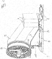
- FIG. 1 is a side perspective view of a vehicle tank 1 in accordance with the invention.
- the tank 1 has a right angled triangular cross section defined by an upper mounting surface 2, a iower surface 8 and a vertical surface 10.
- Such a tank 1 is located under the bonnet (not shown) at the front of the tractor.
- the tank 1 is provided with an upper mounting surface on its exterior 2 to which a fan 3 and radiator or radiators 4 are mounted.
- the fan 3 and radiator(s) 4 stand in an upright position on the upper mounting surface 2 of the tank 1.
- the fan 3 is located at the front of the tractor and when the bonnet is closed, air from outside enters the fan 3 through a grill in the bonnet (not shown).
- the fan 3 is provided with a shroud 5 which extends from the fan to the radiator(s) 4.
- the shroud 5 and upper mounting surface 2 form a channel which guides cooling air from the fan to the radiator(s).
- the fan 3, radiators 4, shroud 5 and tank 1 comprise the cooling arrangement of the tractor.
- Upper mounting surface 2 is sloped.
- Mounting surface 2 provides a fan mounting surface part 6 to which the fan is attached and a radiator mounting part 7 to which the radiator(s) is attached.
- Fan mounting surface part 6 may comprise a curve as shown in figure 3 for co operating with the circumference of the fan. When the tank is fitted to the tractor, fan mounting surface part 6 is higher relative to the radiator mounting part 7.
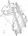
- Lower surface 8 of the tank 1 is the surface which forms the base of the tank and which is attached to the chassis, or frame 9 of the tractor as shown in figure 2 .
- the lower surface 8 extends in a horizontal plane across the frames.
- Figure 2 shows a perspective view of the tank 1 from underneath the frame 9 looking upwards.
- Vertical surface 10 connects the lower surface 8 and upper surface 2. When fitted in the tractor, vertical surface 10 lies in a generally vertical plane.
- the space between the three surfaces, the upper surface 2, lower surface 8 and vertical surface 10 defines the tank 1 which is used to store fluids.
- the tank 1 may be used to store hydraulic fluid to work the fan belt mechanism of the fan 3. Since the tank 1 sits below the fan 3, it saves having to pipe fluid from other tanks on the tractor for the fan mechanism thus saving space, time and costs during manufacture.
- the tank 1 is part of a cooling arrangement of the vehicle.
- the tank 1 is a one piece manufactured by injection moulding and allows a further 27 litres to be stored on the tractor.
Landscapes
- Engineering & Computer Science (AREA)
- Chemical & Material Sciences (AREA)
- Combustion & Propulsion (AREA)
- Mechanical Engineering (AREA)
- Transportation (AREA)
- General Engineering & Computer Science (AREA)
- Life Sciences & Earth Sciences (AREA)
- Sustainable Development (AREA)
- Sustainable Energy (AREA)
- Cooling, Air Intake And Gas Exhaust, And Fuel Tank Arrangements In Propulsion Units (AREA)
Abstract
Description
- This Invention relates to a tank on a vehicle. More specifically, this Invention relates to a tank of a cooling arrangement on an agricultural tractor.
- Agricultural tractors require a number of radiators at the front of the tractor In order to cool a number of working parts, such as a water cooler and a charge air cooler (CAC) for the engine, a transmission oil cooler and a hydraulic oii cooler. It is common practice to arrange the radiators in a series under the vehicle bonnet so that air from a fan positioned at the front of the tractor drives air through the radiators. Fans are usually hydraulically driven by belt means.
- As the trend for larger sized engines increases, so does the requirement for an effective means to cool the engine and its parts. This has led to the requirement for larger sized fans, which in turn require a greater amount of fluid to drive an associated fan belt than previously required. An efficient means to convey cooling air from the fan to the radiators is also necessary.
- To concentrate the flow of air from the fan to the first radiator, that is the first radiator downstream of the fan, the fan is usually provided with a fan shroud which projects in a direction towards the radiators. The fan shroud typically borders the circumference of the fan and extends a short distance parallel, or substantially parallel to the longitudinal axis of the vehicle. In a further arrangement disclosed in the applicant's patent application
PCT/EP2014/065620 - However, to work the fan, fluid from fluid tanks on the vehicle, such as from the front axle must be delivered to the fan mechanism. This fluid is conducted by pipes/tubes which adds to the cost of the vehicle and can also create problems due to the lack of space under the bonnet.
- It is an aim of the invention to provide a vehicle tank which overcomes, or at least alleviates some of the aforementioned problems associated with a vehicle cooling arrangement.
- According to the invention, there is provided a vehicle tank comprising an upper outer surface for mounting a fan and radiator thereto, said upper outer surface comprising a sloped surface between a fan mounting surface part and a radiator mounting surface part so that there is a difference in the relative heights of the two mounting surface parts, said tank further comprising a iower outer surface having a horizontal plane for abutment with a chassis or vehicle frame, and wherein the space between said upper and iower outer surfaces provides a space to hold a fluid.
- The invention thus provides a tank which supports the fan and radiators and provides a fluid holder which is in close proximity to the fan. This avoids the necessity of having to pipe fluid from other tanks on the tractor to the fan mechanism which saves space on the tractor and time and costs during manufacture.
- Preferably, the tank is part of a cooling arrangement of the vehicle. The form of the tank assists in channeling air from the fan to the radiators.
- More preferably the tank is manufactured by injection moulding.
- The vehicle tank is preferably an agricultural tractor tank.
- The invention wiii now be described, by way of example only, with reference to the following drawings in which:
-
Figure 1 is a side perspective view of a vehicle tank in accordance with the invention, -
Figure 2 is a perspective view from below the vehicle tank offigure 1 , and -
Figure 3 is perspective view from above of the vehicle tank offigure 1 . -
Figure 1 is a side perspective view of avehicle tank 1 in accordance with the invention. Thetank 1 has a right angled triangular cross section defined by anupper mounting surface 2, aiower surface 8 and avertical surface 10. Such atank 1 is located under the bonnet (not shown) at the front of the tractor. Thetank 1 is provided with an upper mounting surface on itsexterior 2 to which afan 3 and radiator or radiators 4 are mounted. Typically thefan 3 and radiator(s) 4 stand in an upright position on theupper mounting surface 2 of thetank 1. Thefan 3 is located at the front of the tractor and when the bonnet is closed, air from outside enters thefan 3 through a grill in the bonnet (not shown). Thefan 3 is provided with ashroud 5 which extends from the fan to the radiator(s) 4. Theshroud 5 andupper mounting surface 2 form a channel which guides cooling air from the fan to the radiator(s). Thefan 3, radiators 4,shroud 5 andtank 1 comprise the cooling arrangement of the tractor. -
Upper mounting surface 2 is sloped.Mounting surface 2 provides a fanmounting surface part 6 to which the fan is attached and aradiator mounting part 7 to which the radiator(s) is attached. Fanmounting surface part 6 may comprise a curve as shown infigure 3 for co operating with the circumference of the fan. When the tank is fitted to the tractor, fanmounting surface part 6 is higher relative to theradiator mounting part 7. -
Lower surface 8 of thetank 1 is the surface which forms the base of the tank and which is attached to the chassis, or frame 9 of the tractor as shown infigure 2 . When thetank 1 is fitted to the tractor, thelower surface 8 extends in a horizontal plane across the frames.Figure 2 shows a perspective view of thetank 1 from underneath the frame 9 looking upwards. -
Vertical surface 10 connects thelower surface 8 andupper surface 2. When fitted in the tractor,vertical surface 10 lies in a generally vertical plane. - The space between the three surfaces, the
upper surface 2,lower surface 8 andvertical surface 10 defines thetank 1 which is used to store fluids. For example, thetank 1 may be used to store hydraulic fluid to work the fan belt mechanism of thefan 3. Since thetank 1 sits below thefan 3, it saves having to pipe fluid from other tanks on the tractor for the fan mechanism thus saving space, time and costs during manufacture. Thetank 1 is part of a cooling arrangement of the vehicle. - The
tank 1 is a one piece manufactured by injection moulding and allows a further 27 litres to be stored on the tractor.
Claims (4)
- A vehicle tank comprising an upper outer surface for mounting a fan and radiator thereto, said upper outer surface comprising a sloped surface between a fan mounting surface part and a radiator mounting surface part so that there is a difference in the relative heights of the two mounting surface parts, said tank further comprising a lower outer surface having a horizontal plane for abutment with a chassis or vehicle frame, and wherein the space between said upper and lower outer surfaces provides a space to hold a fluid.
- A vehicle tank as claimed in claim 1 wherein the tank is part of a cooling arrangement of the vehicle.
- A vehicle tank as claimed in claim 1 or claim 2 manufactured by injection moulding.
- A vehicle tank as claimed in any preceding claim wherein the vehicle is an agricultural tractor.
Applications Claiming Priority (1)
| Application Number | Priority Date | Filing Date | Title |
|---|---|---|---|
| GBGB1615151.6A GB201615151D0 (en) | 2016-09-07 | 2016-09-07 | Vehicle tank |
Publications (2)
| Publication Number | Publication Date |
|---|---|
| EP3299201A1 true EP3299201A1 (en) | 2018-03-28 |
| EP3299201B1 EP3299201B1 (en) | 2019-06-26 |
Family
ID=57139750
Family Applications (1)
| Application Number | Title | Priority Date | Filing Date |
|---|---|---|---|
| EP17186707.0A Not-in-force EP3299201B1 (en) | 2016-09-07 | 2017-08-17 | Vehicle tank |
Country Status (3)
| Country | Link |
|---|---|
| US (1) | US10144277B2 (en) |
| EP (1) | EP3299201B1 (en) |
| GB (1) | GB201615151D0 (en) |
Citations (4)
| Publication number | Priority date | Publication date | Assignee | Title |
|---|---|---|---|---|
| EP1329682A2 (en) * | 2002-01-18 | 2003-07-23 | Clark Equipment Company | Integrated fluid reservoir and heat exchanger ducts |
| DE102012020716A1 (en) * | 2012-10-23 | 2014-04-24 | Daimler Ag | Mounting arrangement for fastening module portion on motor vehicle, has holding element that is moved from pre-assembly position into final assembly position so that module portion is fixed at other holding element in mounting position |
| WO2015007914A1 (en) * | 2013-07-19 | 2015-01-22 | Agco International Gmbh | Fan shroud on an agricultural vehicle |
| EP3009624A1 (en) * | 2014-10-13 | 2016-04-20 | Deere & Company | Method for the combined pre-heating and cooling of a coolant |
Family Cites Families (18)
| Publication number | Priority date | Publication date | Assignee | Title |
|---|---|---|---|---|
| US1369540A (en) * | 1919-01-30 | 1921-02-22 | Pribula John | Tractor |
| US1458129A (en) * | 1919-10-29 | 1923-06-12 | Edward T Curran | Water-circulating system |
| DE2834789A1 (en) | 1978-08-09 | 1980-02-14 | Teves Gmbh Alfred | Double fluid reservoir for car - has min. level duct and vent hole via filler |
| DE19702183A1 (en) * | 1997-01-23 | 1998-07-30 | Laengerer & Reich Gmbh & Co | Cooling module |
| US5928535A (en) * | 1997-05-08 | 1999-07-27 | Miller Electric Manufacturing Co. | Fuel tank filler assembly for engine driven welder |
| US6109310A (en) * | 1998-12-29 | 2000-08-29 | Illinois Tool Works, Inc. | Fuel tank vent system with orifice |
| US6523507B2 (en) | 2001-07-20 | 2003-02-25 | Kohler Co. | Fan shroud with snap-on coolant bottle |
| US6926110B2 (en) * | 2003-07-11 | 2005-08-09 | Harley Davidson Motor Company Group, Inc. | Oil tank cover |
| US7077228B1 (en) * | 2004-07-08 | 2006-07-18 | White Reed J | Integral oil tank and chin spoiler for a motorcycle |
| JP2006151131A (en) * | 2004-11-26 | 2006-06-15 | Yamaha Motor Co Ltd | vehicle |
| JP4647507B2 (en) * | 2006-01-31 | 2011-03-09 | 本田技研工業株式会社 | Reserve tank structure |
| US7931397B2 (en) * | 2007-02-27 | 2011-04-26 | Mcneilus Truck And Manufacturing, Inc. | Under pedestal tank arrangement |
| US8613543B2 (en) * | 2007-12-13 | 2013-12-24 | Mcneilus Truck And Manufacturing, Inc. | Under drum water tank |
| JP2010070062A (en) | 2008-09-18 | 2010-04-02 | Toyota Motor Corp | Pipe connection structure |
| JP5168343B2 (en) | 2010-11-15 | 2013-03-21 | マツダ株式会社 | Arrangement structure of fuel tank for vehicle |
| KR20130026635A (en) | 2011-09-06 | 2013-03-14 | 주식회사 만도 | Reservoir tank of brake master cylinder |
| JP5205536B1 (en) * | 2012-06-28 | 2013-06-05 | 株式会社小松製作所 | Wheel loader |
| DE102012020706B4 (en) | 2012-10-23 | 2025-03-20 | Deutz Aktiengesellschaft | Method for operating an internal combustion engine |
-
2016
- 2016-09-07 GB GBGB1615151.6A patent/GB201615151D0/en not_active Ceased
-
2017
- 2017-08-17 EP EP17186707.0A patent/EP3299201B1/en not_active Not-in-force
- 2017-09-01 US US15/693,769 patent/US10144277B2/en active Active
Patent Citations (4)
| Publication number | Priority date | Publication date | Assignee | Title |
|---|---|---|---|---|
| EP1329682A2 (en) * | 2002-01-18 | 2003-07-23 | Clark Equipment Company | Integrated fluid reservoir and heat exchanger ducts |
| DE102012020716A1 (en) * | 2012-10-23 | 2014-04-24 | Daimler Ag | Mounting arrangement for fastening module portion on motor vehicle, has holding element that is moved from pre-assembly position into final assembly position so that module portion is fixed at other holding element in mounting position |
| WO2015007914A1 (en) * | 2013-07-19 | 2015-01-22 | Agco International Gmbh | Fan shroud on an agricultural vehicle |
| EP3009624A1 (en) * | 2014-10-13 | 2016-04-20 | Deere & Company | Method for the combined pre-heating and cooling of a coolant |
Also Published As
| Publication number | Publication date |
|---|---|
| EP3299201B1 (en) | 2019-06-26 |
| GB201615151D0 (en) | 2016-10-19 |
| US10144277B2 (en) | 2018-12-04 |
| US20180065470A1 (en) | 2018-03-08 |
Similar Documents
| Publication | Publication Date | Title |
|---|---|---|
| US8230957B2 (en) | Flow-inducing baffle for engine compartment ventilation | |
| US5234051A (en) | Compact heat exchanger-ventilation unit for a vehicle | |
| US7559295B2 (en) | Cooling structure for a work vehicle | |
| CN102039811A (en) | Construction machine | |
| US10279677B2 (en) | Motor vehicle undertray trim panel having an air inlet | |
| FR3057341B1 (en) | COMPACT LIQUID COOLING COMPACT MODULE | |
| EP1849684A2 (en) | Utility vehicle, in particular an agricultural tractor | |
| CN108928229B (en) | Heat Exchanger for Vehicles | |
| US9561717B2 (en) | Fan shroud on an agricultural vehicle | |
| US7743868B2 (en) | Radiator mounting for a motorcycle | |
| US20070000705A1 (en) | Radiator module for commercial motor vehicles | |
| US20200263685A1 (en) | Hydraulic unit | |
| US10189348B2 (en) | Motor vehicle undertray trim panel having an air inlet | |
| US9676271B1 (en) | Vehicle cooling arrangement | |
| EP3299201B1 (en) | Vehicle tank | |
| US9616741B2 (en) | Vehicle cooling arrangement | |
| EP2135798B1 (en) | Agricultural utility vehicle comprising a fluid reservoir | |
| JP2018034759A (en) | Vehicle front structure | |
| JP2014214526A (en) | Construction machine | |
| JP2017095049A (en) | Vehicle cooling system | |
| WO2016012030A1 (en) | Cooling arrangement on an agricultural vehicle | |
| CN201963388U (en) | Truck engine cooling device | |
| CN105612292B (en) | Arrangement of components of a cooling unit in a construction machine | |
| KR200490125Y1 (en) | Saddle type rice transplanter | |
| EP3267074A1 (en) | Utility vehicle lubrication and cooling |
Legal Events
| Date | Code | Title | Description |
|---|---|---|---|
| PUAI | Public reference made under article 153(3) epc to a published international application that has entered the european phase |
Free format text: ORIGINAL CODE: 0009012 |
|
| STAA | Information on the status of an ep patent application or granted ep patent |
Free format text: STATUS: THE APPLICATION HAS BEEN PUBLISHED |
|
| AK | Designated contracting states |
Kind code of ref document: A1 Designated state(s): AL AT BE BG CH CY CZ DE DK EE ES FI FR GB GR HR HU IE IS IT LI LT LU LV MC MK MT NL NO PL PT RO RS SE SI SK SM TR |
|
| AX | Request for extension of the european patent |
Extension state: BA ME |
|
| STAA | Information on the status of an ep patent application or granted ep patent |
Free format text: STATUS: REQUEST FOR EXAMINATION WAS MADE |
|
| 17P | Request for examination filed |
Effective date: 20180928 |
|
| RBV | Designated contracting states (corrected) |
Designated state(s): AL AT BE BG CH CY CZ DE DK EE ES FI FR GB GR HR HU IE IS IT LI LT LU LV MC MK MT NL NO PL PT RO RS SE SI SK SM TR |
|
| RIC1 | Information provided on ipc code assigned before grant |
Ipc: F01P 3/20 20060101ALI20181127BHEP Ipc: B60K 15/063 20060101ALI20181127BHEP Ipc: F01P 11/10 20060101ALI20181127BHEP Ipc: B60K 11/04 20060101AFI20181127BHEP |
|
| GRAP | Despatch of communication of intention to grant a patent |
Free format text: ORIGINAL CODE: EPIDOSNIGR1 |
|
| STAA | Information on the status of an ep patent application or granted ep patent |
Free format text: STATUS: GRANT OF PATENT IS INTENDED |
|
| INTG | Intention to grant announced |
Effective date: 20190125 |
|
| GRAS | Grant fee paid |
Free format text: ORIGINAL CODE: EPIDOSNIGR3 |
|
| GRAA | (expected) grant |
Free format text: ORIGINAL CODE: 0009210 |
|
| STAA | Information on the status of an ep patent application or granted ep patent |
Free format text: STATUS: THE PATENT HAS BEEN GRANTED |
|
| AK | Designated contracting states |
Kind code of ref document: B1 Designated state(s): AL AT BE BG CH CY CZ DE DK EE ES FI FR GB GR HR HU IE IS IT LI LT LU LV MC MK MT NL NO PL PT RO RS SE SI SK SM TR |
|
| REG | Reference to a national code |
Ref country code: GB Ref legal event code: FG4D |
|
| REG | Reference to a national code |
Ref country code: CH Ref legal event code: EP |
|
| REG | Reference to a national code |
Ref country code: AT Ref legal event code: REF Ref document number: 1147878 Country of ref document: AT Kind code of ref document: T Effective date: 20190715 |
|
| REG | Reference to a national code |
Ref country code: IE Ref legal event code: FG4D |
|
| REG | Reference to a national code |
Ref country code: DE Ref legal event code: R096 Ref document number: 602017004807 Country of ref document: DE |
|
| REG | Reference to a national code |
Ref country code: NL Ref legal event code: MP Effective date: 20190626 |
|
| PG25 | Lapsed in a contracting state [announced via postgrant information from national office to epo] |
Ref country code: NO Free format text: LAPSE BECAUSE OF FAILURE TO SUBMIT A TRANSLATION OF THE DESCRIPTION OR TO PAY THE FEE WITHIN THE PRESCRIBED TIME-LIMIT Effective date: 20190926 Ref country code: FI Free format text: LAPSE BECAUSE OF FAILURE TO SUBMIT A TRANSLATION OF THE DESCRIPTION OR TO PAY THE FEE WITHIN THE PRESCRIBED TIME-LIMIT Effective date: 20190626 Ref country code: HR Free format text: LAPSE BECAUSE OF FAILURE TO SUBMIT A TRANSLATION OF THE DESCRIPTION OR TO PAY THE FEE WITHIN THE PRESCRIBED TIME-LIMIT Effective date: 20190626 Ref country code: SE Free format text: LAPSE BECAUSE OF FAILURE TO SUBMIT A TRANSLATION OF THE DESCRIPTION OR TO PAY THE FEE WITHIN THE PRESCRIBED TIME-LIMIT Effective date: 20190626 Ref country code: AL Free format text: LAPSE BECAUSE OF FAILURE TO SUBMIT A TRANSLATION OF THE DESCRIPTION OR TO PAY THE FEE WITHIN THE PRESCRIBED TIME-LIMIT Effective date: 20190626 Ref country code: LT Free format text: LAPSE BECAUSE OF FAILURE TO SUBMIT A TRANSLATION OF THE DESCRIPTION OR TO PAY THE FEE WITHIN THE PRESCRIBED TIME-LIMIT Effective date: 20190626 |
|
| REG | Reference to a national code |
Ref country code: LT Ref legal event code: MG4D |
|
| PG25 | Lapsed in a contracting state [announced via postgrant information from national office to epo] |
Ref country code: BG Free format text: LAPSE BECAUSE OF FAILURE TO SUBMIT A TRANSLATION OF THE DESCRIPTION OR TO PAY THE FEE WITHIN THE PRESCRIBED TIME-LIMIT Effective date: 20190926 Ref country code: RS Free format text: LAPSE BECAUSE OF FAILURE TO SUBMIT A TRANSLATION OF THE DESCRIPTION OR TO PAY THE FEE WITHIN THE PRESCRIBED TIME-LIMIT Effective date: 20190626 Ref country code: LV Free format text: LAPSE BECAUSE OF FAILURE TO SUBMIT A TRANSLATION OF THE DESCRIPTION OR TO PAY THE FEE WITHIN THE PRESCRIBED TIME-LIMIT Effective date: 20190626 Ref country code: GR Free format text: LAPSE BECAUSE OF FAILURE TO SUBMIT A TRANSLATION OF THE DESCRIPTION OR TO PAY THE FEE WITHIN THE PRESCRIBED TIME-LIMIT Effective date: 20190927 |
|
| REG | Reference to a national code |
Ref country code: AT Ref legal event code: MK05 Ref document number: 1147878 Country of ref document: AT Kind code of ref document: T Effective date: 20190626 |
|
| PG25 | Lapsed in a contracting state [announced via postgrant information from national office to epo] |
Ref country code: RO Free format text: LAPSE BECAUSE OF FAILURE TO SUBMIT A TRANSLATION OF THE DESCRIPTION OR TO PAY THE FEE WITHIN THE PRESCRIBED TIME-LIMIT Effective date: 20190626 Ref country code: SK Free format text: LAPSE BECAUSE OF FAILURE TO SUBMIT A TRANSLATION OF THE DESCRIPTION OR TO PAY THE FEE WITHIN THE PRESCRIBED TIME-LIMIT Effective date: 20190626 Ref country code: EE Free format text: LAPSE BECAUSE OF FAILURE TO SUBMIT A TRANSLATION OF THE DESCRIPTION OR TO PAY THE FEE WITHIN THE PRESCRIBED TIME-LIMIT Effective date: 20190626 Ref country code: AT Free format text: LAPSE BECAUSE OF FAILURE TO SUBMIT A TRANSLATION OF THE DESCRIPTION OR TO PAY THE FEE WITHIN THE PRESCRIBED TIME-LIMIT Effective date: 20190626 Ref country code: PT Free format text: LAPSE BECAUSE OF FAILURE TO SUBMIT A TRANSLATION OF THE DESCRIPTION OR TO PAY THE FEE WITHIN THE PRESCRIBED TIME-LIMIT Effective date: 20191028 Ref country code: CZ Free format text: LAPSE BECAUSE OF FAILURE TO SUBMIT A TRANSLATION OF THE DESCRIPTION OR TO PAY THE FEE WITHIN THE PRESCRIBED TIME-LIMIT Effective date: 20190626 Ref country code: NL Free format text: LAPSE BECAUSE OF FAILURE TO SUBMIT A TRANSLATION OF THE DESCRIPTION OR TO PAY THE FEE WITHIN THE PRESCRIBED TIME-LIMIT Effective date: 20190626 |
|
| PG25 | Lapsed in a contracting state [announced via postgrant information from national office to epo] |
Ref country code: IT Free format text: LAPSE BECAUSE OF FAILURE TO SUBMIT A TRANSLATION OF THE DESCRIPTION OR TO PAY THE FEE WITHIN THE PRESCRIBED TIME-LIMIT Effective date: 20190626 Ref country code: SM Free format text: LAPSE BECAUSE OF FAILURE TO SUBMIT A TRANSLATION OF THE DESCRIPTION OR TO PAY THE FEE WITHIN THE PRESCRIBED TIME-LIMIT Effective date: 20190626 Ref country code: IS Free format text: LAPSE BECAUSE OF FAILURE TO SUBMIT A TRANSLATION OF THE DESCRIPTION OR TO PAY THE FEE WITHIN THE PRESCRIBED TIME-LIMIT Effective date: 20191026 Ref country code: ES Free format text: LAPSE BECAUSE OF FAILURE TO SUBMIT A TRANSLATION OF THE DESCRIPTION OR TO PAY THE FEE WITHIN THE PRESCRIBED TIME-LIMIT Effective date: 20190626 |
|
| PG25 | Lapsed in a contracting state [announced via postgrant information from national office to epo] |
Ref country code: TR Free format text: LAPSE BECAUSE OF FAILURE TO SUBMIT A TRANSLATION OF THE DESCRIPTION OR TO PAY THE FEE WITHIN THE PRESCRIBED TIME-LIMIT Effective date: 20190626 |
|
| PG25 | Lapsed in a contracting state [announced via postgrant information from national office to epo] |
Ref country code: PL Free format text: LAPSE BECAUSE OF FAILURE TO SUBMIT A TRANSLATION OF THE DESCRIPTION OR TO PAY THE FEE WITHIN THE PRESCRIBED TIME-LIMIT Effective date: 20190626 Ref country code: DK Free format text: LAPSE BECAUSE OF FAILURE TO SUBMIT A TRANSLATION OF THE DESCRIPTION OR TO PAY THE FEE WITHIN THE PRESCRIBED TIME-LIMIT Effective date: 20190626 |
|
| PG25 | Lapsed in a contracting state [announced via postgrant information from national office to epo] |
Ref country code: LU Free format text: LAPSE BECAUSE OF NON-PAYMENT OF DUE FEES Effective date: 20190817 Ref country code: IS Free format text: LAPSE BECAUSE OF FAILURE TO SUBMIT A TRANSLATION OF THE DESCRIPTION OR TO PAY THE FEE WITHIN THE PRESCRIBED TIME-LIMIT Effective date: 20200320 Ref country code: MC Free format text: LAPSE BECAUSE OF FAILURE TO SUBMIT A TRANSLATION OF THE DESCRIPTION OR TO PAY THE FEE WITHIN THE PRESCRIBED TIME-LIMIT Effective date: 20190626 |
|
| REG | Reference to a national code |
Ref country code: BE Ref legal event code: MM Effective date: 20190831 |
|
| REG | Reference to a national code |
Ref country code: DE Ref legal event code: R097 Ref document number: 602017004807 Country of ref document: DE |
|
| PLBE | No opposition filed within time limit |
Free format text: ORIGINAL CODE: 0009261 |
|
| STAA | Information on the status of an ep patent application or granted ep patent |
Free format text: STATUS: NO OPPOSITION FILED WITHIN TIME LIMIT |
|
| PG2D | Information on lapse in contracting state deleted |
Ref country code: IS |
|
| PG25 | Lapsed in a contracting state [announced via postgrant information from national office to epo] |
Ref country code: IE Free format text: LAPSE BECAUSE OF NON-PAYMENT OF DUE FEES Effective date: 20190817 |
|
| 26N | No opposition filed |
Effective date: 20200603 |
|
| PG25 | Lapsed in a contracting state [announced via postgrant information from national office to epo] |
Ref country code: SI Free format text: LAPSE BECAUSE OF FAILURE TO SUBMIT A TRANSLATION OF THE DESCRIPTION OR TO PAY THE FEE WITHIN THE PRESCRIBED TIME-LIMIT Effective date: 20190626 Ref country code: BE Free format text: LAPSE BECAUSE OF NON-PAYMENT OF DUE FEES Effective date: 20190831 |
|
| REG | Reference to a national code |
Ref country code: CH Ref legal event code: PL |
|
| PG25 | Lapsed in a contracting state [announced via postgrant information from national office to epo] |
Ref country code: CH Free format text: LAPSE BECAUSE OF NON-PAYMENT OF DUE FEES Effective date: 20200831 Ref country code: LI Free format text: LAPSE BECAUSE OF NON-PAYMENT OF DUE FEES Effective date: 20200831 |
|
| PG25 | Lapsed in a contracting state [announced via postgrant information from national office to epo] |
Ref country code: CY Free format text: LAPSE BECAUSE OF FAILURE TO SUBMIT A TRANSLATION OF THE DESCRIPTION OR TO PAY THE FEE WITHIN THE PRESCRIBED TIME-LIMIT Effective date: 20190626 |
|
| PG25 | Lapsed in a contracting state [announced via postgrant information from national office to epo] |
Ref country code: HU Free format text: LAPSE BECAUSE OF FAILURE TO SUBMIT A TRANSLATION OF THE DESCRIPTION OR TO PAY THE FEE WITHIN THE PRESCRIBED TIME-LIMIT; INVALID AB INITIO Effective date: 20170817 Ref country code: MT Free format text: LAPSE BECAUSE OF FAILURE TO SUBMIT A TRANSLATION OF THE DESCRIPTION OR TO PAY THE FEE WITHIN THE PRESCRIBED TIME-LIMIT Effective date: 20190626 |
|
| PG25 | Lapsed in a contracting state [announced via postgrant information from national office to epo] |
Ref country code: MK Free format text: LAPSE BECAUSE OF FAILURE TO SUBMIT A TRANSLATION OF THE DESCRIPTION OR TO PAY THE FEE WITHIN THE PRESCRIBED TIME-LIMIT Effective date: 20190626 |
|
| P01 | Opt-out of the competence of the unified patent court (upc) registered |
Effective date: 20230518 |
|
| PGFP | Annual fee paid to national office [announced via postgrant information from national office to epo] |
Ref country code: GB Payment date: 20230822 Year of fee payment: 7 |
|
| PGFP | Annual fee paid to national office [announced via postgrant information from national office to epo] |
Ref country code: FR Payment date: 20230825 Year of fee payment: 7 Ref country code: DE Payment date: 20230821 Year of fee payment: 7 |
|
| REG | Reference to a national code |
Ref country code: DE Ref legal event code: R119 Ref document number: 602017004807 Country of ref document: DE |
|
| GBPC | Gb: european patent ceased through non-payment of renewal fee |
Effective date: 20240817 |
|
| PG25 | Lapsed in a contracting state [announced via postgrant information from national office to epo] |
Ref country code: DE Free format text: LAPSE BECAUSE OF NON-PAYMENT OF DUE FEES Effective date: 20250301 |
|
| PG25 | Lapsed in a contracting state [announced via postgrant information from national office to epo] |
Ref country code: GB Free format text: LAPSE BECAUSE OF NON-PAYMENT OF DUE FEES Effective date: 20240817 |
|
| PG25 | Lapsed in a contracting state [announced via postgrant information from national office to epo] |
Ref country code: FR Free format text: LAPSE BECAUSE OF NON-PAYMENT OF DUE FEES Effective date: 20240831 |