EP3299179A1 - Tool for changing the callipers in disc brakes - Google Patents
Tool for changing the callipers in disc brakes Download PDFInfo
- Publication number
- EP3299179A1 EP3299179A1 EP16795928.7A EP16795928A EP3299179A1 EP 3299179 A1 EP3299179 A1 EP 3299179A1 EP 16795928 A EP16795928 A EP 16795928A EP 3299179 A1 EP3299179 A1 EP 3299179A1
- Authority
- EP
- European Patent Office
- Prior art keywords
- tool
- changing
- plate
- disc brakes
- inclination
- Prior art date
- Legal status (The legal status is an assumption and is not a legal conclusion. Google has not performed a legal analysis and makes no representation as to the accuracy of the status listed.)
- Withdrawn
Links
Images

Classifications
-
- B—PERFORMING OPERATIONS; TRANSPORTING
- B66—HOISTING; LIFTING; HAULING
- B66C—CRANES; LOAD-ENGAGING ELEMENTS OR DEVICES FOR CRANES, CAPSTANS, WINCHES, OR TACKLES
- B66C23/00—Cranes comprising essentially a beam, boom, or triangular structure acting as a cantilever and mounted for translatory of swinging movements in vertical or horizontal planes or a combination of such movements, e.g. jib-cranes, derricks, tower cranes
- B66C23/18—Cranes comprising essentially a beam, boom, or triangular structure acting as a cantilever and mounted for translatory of swinging movements in vertical or horizontal planes or a combination of such movements, e.g. jib-cranes, derricks, tower cranes specially adapted for use in particular purposes
- B66C23/36—Cranes comprising essentially a beam, boom, or triangular structure acting as a cantilever and mounted for translatory of swinging movements in vertical or horizontal planes or a combination of such movements, e.g. jib-cranes, derricks, tower cranes specially adapted for use in particular purposes mounted on road or rail vehicles; Manually-movable jib-cranes for use in workshops; Floating cranes
- B66C23/48—Manually-movable jib cranes for use in workshops
-
- B—PERFORMING OPERATIONS; TRANSPORTING
- B25—HAND TOOLS; PORTABLE POWER-DRIVEN TOOLS; MANIPULATORS
- B25B—TOOLS OR BENCH DEVICES NOT OTHERWISE PROVIDED FOR, FOR FASTENING, CONNECTING, DISENGAGING, OR HOLDING
- B25B11/00—Work holders not covered by any preceding group in the subclass, e.g. magnetic work holders, vacuum work holders
-
- B—PERFORMING OPERATIONS; TRANSPORTING
- B25—HAND TOOLS; PORTABLE POWER-DRIVEN TOOLS; MANIPULATORS
- B25H—WORKSHOP EQUIPMENT, e.g. FOR MARKING-OUT WORK; STORAGE MEANS FOR WORKSHOPS
- B25H1/00—Work benches; Portable stands or supports for positioning portable tools or work to be operated on thereby
- B25H1/0007—Work benches; Portable stands or supports for positioning portable tools or work to be operated on thereby for engines, motor-vehicles or bicycles
-
- B—PERFORMING OPERATIONS; TRANSPORTING
- B25—HAND TOOLS; PORTABLE POWER-DRIVEN TOOLS; MANIPULATORS
- B25H—WORKSHOP EQUIPMENT, e.g. FOR MARKING-OUT WORK; STORAGE MEANS FOR WORKSHOPS
- B25H1/00—Work benches; Portable stands or supports for positioning portable tools or work to be operated on thereby
- B25H1/0021—Stands, supports or guiding devices for positioning portable tools or for securing them to the work
- B25H1/0028—Tool balancers
-
- B—PERFORMING OPERATIONS; TRANSPORTING
- B25—HAND TOOLS; PORTABLE POWER-DRIVEN TOOLS; MANIPULATORS
- B25H—WORKSHOP EQUIPMENT, e.g. FOR MARKING-OUT WORK; STORAGE MEANS FOR WORKSHOPS
- B25H1/00—Work benches; Portable stands or supports for positioning portable tools or work to be operated on thereby
- B25H1/0021—Stands, supports or guiding devices for positioning portable tools or for securing them to the work
- B25H1/0035—Extensible supports, e.g. telescopic
-
- B—PERFORMING OPERATIONS; TRANSPORTING
- B60—VEHICLES IN GENERAL
- B60B—VEHICLE WHEELS; CASTORS; AXLES FOR WHEELS OR CASTORS; INCREASING WHEEL ADHESION
- B60B29/00—Apparatus or tools for mounting or dismounting wheels
-
- B—PERFORMING OPERATIONS; TRANSPORTING
- B60—VEHICLES IN GENERAL
- B60T—VEHICLE BRAKE CONTROL SYSTEMS OR PARTS THEREOF; BRAKE CONTROL SYSTEMS OR PARTS THEREOF, IN GENERAL; ARRANGEMENT OF BRAKING ELEMENTS ON VEHICLES IN GENERAL; PORTABLE DEVICES FOR PREVENTING UNWANTED MOVEMENT OF VEHICLES; VEHICLE MODIFICATIONS TO FACILITATE COOLING OF BRAKES
- B60T17/00—Component parts, details, or accessories of power brake systems not covered by groups B60T8/00, B60T13/00 or B60T15/00, or presenting other characteristic features
- B60T17/18—Safety devices; Monitoring
- B60T17/22—Devices for monitoring or checking brake systems; Signal devices
-
- F—MECHANICAL ENGINEERING; LIGHTING; HEATING; WEAPONS; BLASTING
- F16—ENGINEERING ELEMENTS AND UNITS; GENERAL MEASURES FOR PRODUCING AND MAINTAINING EFFECTIVE FUNCTIONING OF MACHINES OR INSTALLATIONS; THERMAL INSULATION IN GENERAL
- F16D—COUPLINGS FOR TRANSMITTING ROTATION; CLUTCHES; BRAKES
- F16D2250/00—Manufacturing; Assembly
- F16D2250/0084—Assembly or disassembly
Definitions
- the object of the present invention is a device for assembling and disassembling calipers of disc brakes on transportation vehicles, such as trailers or trucks, which makes them easy to replace, even by a single person.
- the object of the present invention is a tool for changing the calipers of disc brakes on trailers or towing vehicles for land transport. This objective is achieved by means of the tool described in the independent claim that is attached to the present specification and which is incorporated herein as a reference to the same. The specific embodiments of the tool are described in the dependent claims that are likewise incorporated into the present description as a reference.
- the tool for changing calipers of a disc brake on road transportation vehicles object of the present invention, comprises a base or support 1 that is mobile thanks to a plurality of wheels 2 arranged in such a way so as to facilitate the movement thereof throughout the workshop and facilitate the best position for changing the calipers 10.
- a telescopically adjustable neck 3 that can be adjusted by means of an adjuster 4, preferably of the type that screws, such that said neck 3 can face the caliper 10 in the best possible position before being changed.
- the neck 3 comprises an inverted L-shaped body 5 at the top part thereof, the ends of which are joined by means of a plate 6 that comprises a plurality of coupling screws 7, two in this specific embodiment, placed between two parallel plates 8 with slotted holes 8a in order to allow for a better positioning of the coupling screws 7 in a position of use.
- the plate 6 is foldable with respect to a folding axis 9 and adjustable in its angle of inclination ( ⁇ ) thanks to an adjuster that adjusts the inclination, in this specific embodiment being a bolt 9a in the folding axis 9 and a tensioner 9b arranged on the neck 3 and which adapts the position of the plate 6 when it folds with respect to the caliper 10 due to the fact that the tensioner 9b moves towards the plate 6 against the caliper 10 itself.
- ⁇ angle of inclination
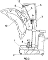
- Figure 2 shows the tool with the caliper 10 coupled to the plate 6 by means of coupling screws 7 and fixed by a bolt at the top 12.
- the use of the tool is quite simple. After placing the tool close to the brake, the brake's air chamber is removed and the tool is placed facing the caliper 10 to subsequently remove the screws from the caliper. Once the screws joining the caliper 10 to the body of the brake are removed, the same is screwed to the plate 6 by means of the coupling screws 7, adjusting the height 4 and the inclination ( ⁇ ) using the height adjuster 4 and the inclination adjuster (9a, 9b) with respect to the folding axis 9. Once the caliper is fixed to the plate 6 of the tool, the same is then effortlessly removed, since the weight of the caliper is compensated for by a counterweight 11 arranged on the base 1.
Landscapes
- Engineering & Computer Science (AREA)
- Mechanical Engineering (AREA)
- Transportation (AREA)
- Braking Arrangements (AREA)
Abstract
Description
- The object of the present invention is a device for assembling and disassembling calipers of disc brakes on transportation vehicles, such as trailers or trucks, which makes them easy to replace, even by a single person.
- One of the most common mechanical failures of road transportation vehicles, both for towing vehicles and trailers, is due to a failure in the disc brakes. Nowadays, to disassemble the calipers of the disc brakes on trailers or trucks, there are no tools that can be used to avoid having to manually assemble or disassemble the same. Furthermore, due to the weight of the parts involved in the labor, which range around 40kg, it is necessary that two people perform said assembly or disassembly.
- Manual assembling or disassembling leads to serious problems, some of which include strain on the workers and the possibility of work-related accidents, since these parts, as was previously mentioned, are considerably heavy, making it recommendable that two mechanics perform the task, which is not always possible. Therefore, it is necessary to have a tool or device that allows the brake calipers to be changed without the physical labor of the worker involved.
- The object of the present invention is a tool for changing the calipers of disc brakes on trailers or towing vehicles for land transport. This objective is achieved by means of the tool described in the independent claim that is attached to the present specification and which is incorporated herein as a reference to the same. The specific embodiments of the tool are described in the dependent claims that are likewise incorporated into the present description as a reference.
- Thanks to the tool described, the technical problems related to changing or replacing calipers due to the heavy weight thereof are solved, and, furthermore, a new tool, unknown until now in the sector, is unveiled.
- Throughout the description and the claims the word "comprise" and the variants thereof do not aim to exclude other technical characteristics, additions, components or steps. For those skilled in the art, other objects, advantages and characteristics of the invention may be deduced from both the description and the practical use of the invention. Furthermore, the present invention covers all of the possible combinations of particular and preferred embodiments indicated herein.
- What follows is a very brief description of a series of drawings that aid in better understanding the invention, and which are expressly related to an embodiment of said invention that is presented by way of a non-limiting example of the same.
-
FIG 1 shows a view of the tool, object of the present invention. -
FIG 2 shows a view of the tool infigure 1 with a brake caliper coupled to the same, in an operating position. - As can be seen in the attached figures, the tool for changing calipers of a disc brake on road transportation vehicles, object of the present invention, comprises a base or
support 1 that is mobile thanks to a plurality ofwheels 2 arranged in such a way so as to facilitate the movement thereof throughout the workshop and facilitate the best position for changing thecalipers 10. - Perpendicularly emanating from the aforementioned support is a telescopically
adjustable neck 3 that can be adjusted by means of anadjuster 4, preferably of the type that screws, such that saidneck 3 can face thecaliper 10 in the best possible position before being changed. - The
neck 3 comprises an inverted L-shaped body 5 at the top part thereof, the ends of which are joined by means of aplate 6 that comprises a plurality ofcoupling screws 7, two in this specific embodiment, placed between twoparallel plates 8 with slottedholes 8a in order to allow for a better positioning of thecoupling screws 7 in a position of use. - The
plate 6 is foldable with respect to a foldingaxis 9 and adjustable in its angle of inclination (α) thanks to an adjuster that adjusts the inclination, in this specific embodiment being abolt 9a in thefolding axis 9 and atensioner 9b arranged on theneck 3 and which adapts the position of theplate 6 when it folds with respect to thecaliper 10 due to the fact that thetensioner 9b moves towards theplate 6 against thecaliper 10 itself. -
Figure 2 shows the tool with thecaliper 10 coupled to theplate 6 by means ofcoupling screws 7 and fixed by a bolt at thetop 12. The use of the tool is quite simple. After placing the tool close to the brake, the brake's air chamber is removed and the tool is placed facing thecaliper 10 to subsequently remove the screws from the caliper. Once the screws joining thecaliper 10 to the body of the brake are removed, the same is screwed to theplate 6 by means of thecoupling screws 7, adjusting theheight 4 and the inclination (α) using theheight adjuster 4 and the inclination adjuster (9a, 9b) with respect to thefolding axis 9. Once the caliper is fixed to theplate 6 of the tool, the same is then effortlessly removed, since the weight of the caliper is compensated for by acounterweight 11 arranged on thebase 1. - Thus, thanks to the tool herein described, a single worker can effortlessly disassemble the
caliper 10, since they only have to remove the screws from thecaliper 10 and fix the same to the tool, thecaliper 10 remaining in the position shown infigure 2 . Obviously, when the tasks of repairing the brake are finished, the operation will be repeated, placing the caliper on the brake, removing thecoupling screws 7 and placing the screws of the brake to complete the operation.
Claims (3)
- A tool for changing the calipers of disc brakes comprising a mobile base (1) by means of wheels (2) and which comprises a counterweight (11), characterized in that emanating perpendicularly from the base (1) is a telescopic neck (3) that comprises a height adjuster (4) and wherein said neck (3) comprises an inverted L-shaped body (5) on the upper part thereof, the ends of which are joined by means of a plate (6) that comprises a plurality of coupling screws (7), and wherein said plate (6) is foldable with respect to a folding axis (9), the angle of inclination (α) of which is adjustable thanks to an inclination adjuster (9a, 9b).
- The tool of claim 1 in which the coupling screws (7) are placed between two parallel plates (8) with slotted holes (8a).
- The tool of any of claims 1-2 in which the inclination adjuster (9a, 9b) comprises a bolt (9a) in the folding axis (9) and a tensioner (9b) arranged on the neck (3).
Applications Claiming Priority (2)
| Application Number | Priority Date | Filing Date | Title |
|---|---|---|---|
| ES201500354U ES1140306Y (en) | 2015-05-21 | 2015-05-21 | useful for changing calipers on disc brakes |
| PCT/ES2016/000046 WO2016185055A1 (en) | 2015-05-21 | 2016-04-13 | Tool for changing the callipers in disc brakes |
Publications (2)
| Publication Number | Publication Date |
|---|---|
| EP3299179A1 true EP3299179A1 (en) | 2018-03-28 |
| EP3299179A4 EP3299179A4 (en) | 2019-01-23 |
Family
ID=53396653
Family Applications (1)
| Application Number | Title | Priority Date | Filing Date |
|---|---|---|---|
| EP16795928.7A Withdrawn EP3299179A4 (en) | 2015-05-21 | 2016-04-13 | TOOL FOR CHANGING THE DISC BRAKE CALIPERS |
Country Status (5)
| Country | Link |
|---|---|
| US (1) | US20180155163A1 (en) |
| EP (1) | EP3299179A4 (en) |
| CA (1) | CA2986650A1 (en) |
| ES (1) | ES1140306Y (en) |
| WO (1) | WO2016185055A1 (en) |
Cited By (1)
| Publication number | Priority date | Publication date | Assignee | Title |
|---|---|---|---|---|
| CN115648146A (en) * | 2022-12-12 | 2023-01-31 | 射阳兴凯飞航空设备有限公司 | A workstation for supplementary installation of wing wingtip |
Families Citing this family (1)
| Publication number | Priority date | Publication date | Assignee | Title |
|---|---|---|---|---|
| CN112590458A (en) * | 2020-12-07 | 2021-04-02 | 吴翊展 | Tire changing device |
Family Cites Families (12)
| Publication number | Priority date | Publication date | Assignee | Title |
|---|---|---|---|---|
| US2763053A (en) * | 1955-06-09 | 1956-09-18 | Wisconsin Hydraulics Inc | Universal work positioners |
| US3917200A (en) * | 1973-12-14 | 1975-11-04 | Jay Johnson | Pneumatic boom support for hand tools |
| US4239196A (en) * | 1979-05-09 | 1980-12-16 | Hanger James E | Engine stand |
| GB8623520D0 (en) * | 1986-10-01 | 1986-11-05 | Hales P B | Commercial vehicle brake drum and hub lift |
| US5033717A (en) * | 1987-02-13 | 1991-07-23 | Peter Symon | Lifting device for vehicle parts |
| US5897100A (en) * | 1995-05-15 | 1999-04-27 | Napier; Corbett | Apparatus for removing an engine from a van |
| US5863034A (en) * | 1996-10-24 | 1999-01-26 | Vauter; Andrew F. | Work piece stand |
| US5895030A (en) * | 1997-06-13 | 1999-04-20 | Mohun; George E. | Heavy duty device for use in removing and servicing wheel drum and hub assemblies |
| US20050081355A1 (en) * | 2003-10-16 | 2005-04-21 | Nechvatal Robert J. | Air disc brake caliper jack assembly |
| US7766306B2 (en) * | 2007-12-21 | 2010-08-03 | Morey Robert P | Device for removing wheel end components as an assembly on vehicles with ball joints and method for servicing vehicle ball joints |
| DK176850B1 (en) * | 2008-03-30 | 2009-12-07 | Stack O Matic Aps | Lifting gear |
| SE536555C2 (en) * | 2012-06-20 | 2014-02-18 | Scania Cv Ab | Device for mounting and disassembly of caliper and method for mounting and disassembling such caliper |
-
2015
- 2015-05-21 ES ES201500354U patent/ES1140306Y/en not_active Expired - Fee Related
-
2016
- 2016-04-13 US US15/576,030 patent/US20180155163A1/en not_active Abandoned
- 2016-04-13 CA CA2986650A patent/CA2986650A1/en not_active Abandoned
- 2016-04-13 EP EP16795928.7A patent/EP3299179A4/en not_active Withdrawn
- 2016-04-13 WO PCT/ES2016/000046 patent/WO2016185055A1/en not_active Ceased
Cited By (1)
| Publication number | Priority date | Publication date | Assignee | Title |
|---|---|---|---|---|
| CN115648146A (en) * | 2022-12-12 | 2023-01-31 | 射阳兴凯飞航空设备有限公司 | A workstation for supplementary installation of wing wingtip |
Also Published As
| Publication number | Publication date |
|---|---|
| WO2016185055A1 (en) | 2016-11-24 |
| ES1140306Y (en) | 2015-09-15 |
| ES1140306U (en) | 2015-06-22 |
| US20180155163A1 (en) | 2018-06-07 |
| CA2986650A1 (en) | 2016-11-24 |
| EP3299179A4 (en) | 2019-01-23 |
Similar Documents
| Publication | Publication Date | Title |
|---|---|---|
| CN103189728B (en) | Road Simulation Test Bench | |
| US9239126B2 (en) | Twist jack stand apparatus and method | |
| US9254722B2 (en) | Tool for supporting and locking a rim or tired wheel for motorcycles | |
| CN206057512U (en) | Combined motor is to dragging testboard | |
| CN101445026B (en) | Tyre fitting machine | |
| CA2890557C (en) | Steering shock compressor systems and methods | |
| CN104507642B (en) | There is the fixed fixture of the spring of general clamping platform | |
| EP3299179A1 (en) | Tool for changing the callipers in disc brakes | |
| CN105667308B (en) | Acceleration and braking mechanism kit for a vehicle | |
| KR101652001B1 (en) | Spring-load type caster structure | |
| CN105666110B (en) | A kind of device for screwing up for vehicle assembling | |
| US8950760B1 (en) | Three wheeled automotive dolly and method of use | |
| US9573796B1 (en) | Weight supporting apparatus and method | |
| US9895930B2 (en) | Compression jaw support | |
| EP1724563A2 (en) | Lifting device for fitting vehicle wheels on wheel balancers | |
| EP2161235B1 (en) | Lifting device, particularly for lifting wheels of vehicles and the like, for wheel balancing and tire removing machines | |
| BRPI0516719B1 (en) | ADJUSTABLE BACKREST ARRANGEMENT FOR A CYLINDER AND PISTON UNIT | |
| US20140201962A1 (en) | Spindle Removal Tool | |
| EP2735405B1 (en) | An improved press for the reversible disassembling of car shock absorbers | |
| CN204868046U (en) | Assembly line of shock strut unit and drag angle unit | |
| US2538962A (en) | Fluid pressure-operated tire bead loosening tool | |
| CN205085565U (en) | Guide structure of automobile wheel hub jacking device | |
| US2493289A (en) | Buffing stand | |
| KR100440721B1 (en) | Dolly for nose landing gear | |
| CN109501658A (en) | A kind of unmanned plane clamping device |
Legal Events
| Date | Code | Title | Description |
|---|---|---|---|
| STAA | Information on the status of an ep patent application or granted ep patent |
Free format text: STATUS: THE INTERNATIONAL PUBLICATION HAS BEEN MADE |
|
| PUAI | Public reference made under article 153(3) epc to a published international application that has entered the european phase |
Free format text: ORIGINAL CODE: 0009012 |
|
| STAA | Information on the status of an ep patent application or granted ep patent |
Free format text: STATUS: REQUEST FOR EXAMINATION WAS MADE |
|
| 17P | Request for examination filed |
Effective date: 20171121 |
|
| AK | Designated contracting states |
Kind code of ref document: A1 Designated state(s): AL AT BE BG CH CY CZ DE DK EE ES FI FR GB GR HR HU IE IS IT LI LT LU LV MC MK MT NL NO PL PT RO RS SE SI SK SM TR |
|
| AX | Request for extension of the european patent |
Extension state: BA ME |
|
| DAV | Request for validation of the european patent (deleted) | ||
| DAX | Request for extension of the european patent (deleted) | ||
| A4 | Supplementary search report drawn up and despatched |
Effective date: 20190103 |
|
| RIC1 | Information provided on ipc code assigned before grant |
Ipc: B25B 11/00 20060101ALI20181219BHEP Ipc: B60T 17/22 20060101ALI20181219BHEP Ipc: B66C 23/48 20060101ALI20181219BHEP Ipc: B25H 1/00 20060101ALI20181219BHEP Ipc: B60B 29/00 20060101AFI20181219BHEP |
|
| GRAP | Despatch of communication of intention to grant a patent |
Free format text: ORIGINAL CODE: EPIDOSNIGR1 |
|
| STAA | Information on the status of an ep patent application or granted ep patent |
Free format text: STATUS: GRANT OF PATENT IS INTENDED |
|
| INTG | Intention to grant announced |
Effective date: 20191107 |
|
| GRAS | Grant fee paid |
Free format text: ORIGINAL CODE: EPIDOSNIGR3 |
|
| STAA | Information on the status of an ep patent application or granted ep patent |
Free format text: STATUS: THE APPLICATION IS DEEMED TO BE WITHDRAWN |
|
| 18D | Application deemed to be withdrawn |
Effective date: 20201103 |