EP3299160A1 - Bonding arrangement and assigned production method - Google Patents
Bonding arrangement and assigned production method Download PDFInfo
- Publication number
- EP3299160A1 EP3299160A1 EP16189841.6A EP16189841A EP3299160A1 EP 3299160 A1 EP3299160 A1 EP 3299160A1 EP 16189841 A EP16189841 A EP 16189841A EP 3299160 A1 EP3299160 A1 EP 3299160A1
- Authority
- EP
- European Patent Office
- Prior art keywords
- structural elements
- bonding arrangement
- supporting member
- coating structure
- arrangement according
- Prior art date
- Legal status (The legal status is an assumption and is not a legal conclusion. Google has not performed a legal analysis and makes no representation as to the accuracy of the status listed.)
- Withdrawn
Links
Images


Classifications
-
- B—PERFORMING OPERATIONS; TRANSPORTING
- B32—LAYERED PRODUCTS
- B32B—LAYERED PRODUCTS, i.e. PRODUCTS BUILT-UP OF STRATA OF FLAT OR NON-FLAT, e.g. CELLULAR OR HONEYCOMB, FORM
- B32B7/00—Layered products characterised by the relation between layers; Layered products characterised by the relative orientation of features between layers, or by the relative values of a measurable parameter between layers, i.e. products comprising layers having different physical, chemical or physicochemical properties; Layered products characterised by the interconnection of layers
- B32B7/04—Interconnection of layers
- B32B7/12—Interconnection of layers using interposed adhesives or interposed materials with bonding properties
-
- B—PERFORMING OPERATIONS; TRANSPORTING
- B32—LAYERED PRODUCTS
- B32B—LAYERED PRODUCTS, i.e. PRODUCTS BUILT-UP OF STRATA OF FLAT OR NON-FLAT, e.g. CELLULAR OR HONEYCOMB, FORM
- B32B1/00—Layered products having a non-planar shape
-
- B—PERFORMING OPERATIONS; TRANSPORTING
- B32—LAYERED PRODUCTS
- B32B—LAYERED PRODUCTS, i.e. PRODUCTS BUILT-UP OF STRATA OF FLAT OR NON-FLAT, e.g. CELLULAR OR HONEYCOMB, FORM
- B32B15/00—Layered products comprising a layer of metal
-
- B—PERFORMING OPERATIONS; TRANSPORTING
- B32—LAYERED PRODUCTS
- B32B—LAYERED PRODUCTS, i.e. PRODUCTS BUILT-UP OF STRATA OF FLAT OR NON-FLAT, e.g. CELLULAR OR HONEYCOMB, FORM
- B32B15/00—Layered products comprising a layer of metal
- B32B15/04—Layered products comprising a layer of metal comprising metal as the main or only constituent of a layer, which is next to another layer of the same or of a different material
- B32B15/046—Layered products comprising a layer of metal comprising metal as the main or only constituent of a layer, which is next to another layer of the same or of a different material of foam
-
- B—PERFORMING OPERATIONS; TRANSPORTING
- B32—LAYERED PRODUCTS
- B32B—LAYERED PRODUCTS, i.e. PRODUCTS BUILT-UP OF STRATA OF FLAT OR NON-FLAT, e.g. CELLULAR OR HONEYCOMB, FORM
- B32B15/00—Layered products comprising a layer of metal
- B32B15/04—Layered products comprising a layer of metal comprising metal as the main or only constituent of a layer, which is next to another layer of the same or of a different material
- B32B15/08—Layered products comprising a layer of metal comprising metal as the main or only constituent of a layer, which is next to another layer of the same or of a different material of synthetic resin
-
- B—PERFORMING OPERATIONS; TRANSPORTING
- B32—LAYERED PRODUCTS
- B32B—LAYERED PRODUCTS, i.e. PRODUCTS BUILT-UP OF STRATA OF FLAT OR NON-FLAT, e.g. CELLULAR OR HONEYCOMB, FORM
- B32B15/00—Layered products comprising a layer of metal
- B32B15/20—Layered products comprising a layer of metal comprising aluminium or copper
-
- B—PERFORMING OPERATIONS; TRANSPORTING
- B32—LAYERED PRODUCTS
- B32B—LAYERED PRODUCTS, i.e. PRODUCTS BUILT-UP OF STRATA OF FLAT OR NON-FLAT, e.g. CELLULAR OR HONEYCOMB, FORM
- B32B25/00—Layered products comprising a layer of natural or synthetic rubber
-
- B—PERFORMING OPERATIONS; TRANSPORTING
- B32—LAYERED PRODUCTS
- B32B—LAYERED PRODUCTS, i.e. PRODUCTS BUILT-UP OF STRATA OF FLAT OR NON-FLAT, e.g. CELLULAR OR HONEYCOMB, FORM
- B32B25/00—Layered products comprising a layer of natural or synthetic rubber
- B32B25/14—Layered products comprising a layer of natural or synthetic rubber comprising synthetic rubber copolymers
-
- B—PERFORMING OPERATIONS; TRANSPORTING
- B32—LAYERED PRODUCTS
- B32B—LAYERED PRODUCTS, i.e. PRODUCTS BUILT-UP OF STRATA OF FLAT OR NON-FLAT, e.g. CELLULAR OR HONEYCOMB, FORM
- B32B3/00—Layered products comprising a layer with external or internal discontinuities or unevennesses, or a layer of non-planar shape; Layered products comprising a layer having particular features of form
-
- B—PERFORMING OPERATIONS; TRANSPORTING
- B32—LAYERED PRODUCTS
- B32B—LAYERED PRODUCTS, i.e. PRODUCTS BUILT-UP OF STRATA OF FLAT OR NON-FLAT, e.g. CELLULAR OR HONEYCOMB, FORM
- B32B3/00—Layered products comprising a layer with external or internal discontinuities or unevennesses, or a layer of non-planar shape; Layered products comprising a layer having particular features of form
- B32B3/02—Layered products comprising a layer with external or internal discontinuities or unevennesses, or a layer of non-planar shape; Layered products comprising a layer having particular features of form characterised by features of form at particular places, e.g. in edge regions
-
- B—PERFORMING OPERATIONS; TRANSPORTING
- B32—LAYERED PRODUCTS
- B32B—LAYERED PRODUCTS, i.e. PRODUCTS BUILT-UP OF STRATA OF FLAT OR NON-FLAT, e.g. CELLULAR OR HONEYCOMB, FORM
- B32B3/00—Layered products comprising a layer with external or internal discontinuities or unevennesses, or a layer of non-planar shape; Layered products comprising a layer having particular features of form
- B32B3/02—Layered products comprising a layer with external or internal discontinuities or unevennesses, or a layer of non-planar shape; Layered products comprising a layer having particular features of form characterised by features of form at particular places, e.g. in edge regions
- B32B3/06—Layered products comprising a layer with external or internal discontinuities or unevennesses, or a layer of non-planar shape; Layered products comprising a layer having particular features of form characterised by features of form at particular places, e.g. in edge regions for securing layers together; for attaching the product to another member, e.g. to a support, or to another product, e.g. groove/tongue, interlocking
-
- B—PERFORMING OPERATIONS; TRANSPORTING
- B32—LAYERED PRODUCTS
- B32B—LAYERED PRODUCTS, i.e. PRODUCTS BUILT-UP OF STRATA OF FLAT OR NON-FLAT, e.g. CELLULAR OR HONEYCOMB, FORM
- B32B3/00—Layered products comprising a layer with external or internal discontinuities or unevennesses, or a layer of non-planar shape; Layered products comprising a layer having particular features of form
- B32B3/10—Layered products comprising a layer with external or internal discontinuities or unevennesses, or a layer of non-planar shape; Layered products comprising a layer having particular features of form characterised by a discontinuous layer, i.e. formed of separate pieces of material
- B32B3/12—Layered products comprising a layer with external or internal discontinuities or unevennesses, or a layer of non-planar shape; Layered products comprising a layer having particular features of form characterised by a discontinuous layer, i.e. formed of separate pieces of material characterised by a layer of regularly- arranged cells, e.g. a honeycomb structure
-
- B—PERFORMING OPERATIONS; TRANSPORTING
- B32—LAYERED PRODUCTS
- B32B—LAYERED PRODUCTS, i.e. PRODUCTS BUILT-UP OF STRATA OF FLAT OR NON-FLAT, e.g. CELLULAR OR HONEYCOMB, FORM
- B32B3/00—Layered products comprising a layer with external or internal discontinuities or unevennesses, or a layer of non-planar shape; Layered products comprising a layer having particular features of form
- B32B3/10—Layered products comprising a layer with external or internal discontinuities or unevennesses, or a layer of non-planar shape; Layered products comprising a layer having particular features of form characterised by a discontinuous layer, i.e. formed of separate pieces of material
- B32B3/18—Layered products comprising a layer with external or internal discontinuities or unevennesses, or a layer of non-planar shape; Layered products comprising a layer having particular features of form characterised by a discontinuous layer, i.e. formed of separate pieces of material characterised by an internal layer formed of separate pieces of material which are juxtaposed side-by-side
- B32B3/22—Layered products comprising a layer with external or internal discontinuities or unevennesses, or a layer of non-planar shape; Layered products comprising a layer having particular features of form characterised by a discontinuous layer, i.e. formed of separate pieces of material characterised by an internal layer formed of separate pieces of material which are juxtaposed side-by-side of spaced pieces
-
- B—PERFORMING OPERATIONS; TRANSPORTING
- B32—LAYERED PRODUCTS
- B32B—LAYERED PRODUCTS, i.e. PRODUCTS BUILT-UP OF STRATA OF FLAT OR NON-FLAT, e.g. CELLULAR OR HONEYCOMB, FORM
- B32B3/00—Layered products comprising a layer with external or internal discontinuities or unevennesses, or a layer of non-planar shape; Layered products comprising a layer having particular features of form
- B32B3/26—Layered products comprising a layer with external or internal discontinuities or unevennesses, or a layer of non-planar shape; Layered products comprising a layer having particular features of form characterised by a particular shape of the outline of the cross-section of a continuous layer; characterised by a layer with cavities or internal voids ; characterised by an apertured layer
-
- B—PERFORMING OPERATIONS; TRANSPORTING
- B32—LAYERED PRODUCTS
- B32B—LAYERED PRODUCTS, i.e. PRODUCTS BUILT-UP OF STRATA OF FLAT OR NON-FLAT, e.g. CELLULAR OR HONEYCOMB, FORM
- B32B3/00—Layered products comprising a layer with external or internal discontinuities or unevennesses, or a layer of non-planar shape; Layered products comprising a layer having particular features of form
- B32B3/26—Layered products comprising a layer with external or internal discontinuities or unevennesses, or a layer of non-planar shape; Layered products comprising a layer having particular features of form characterised by a particular shape of the outline of the cross-section of a continuous layer; characterised by a layer with cavities or internal voids ; characterised by an apertured layer
- B32B3/28—Layered products comprising a layer with external or internal discontinuities or unevennesses, or a layer of non-planar shape; Layered products comprising a layer having particular features of form characterised by a particular shape of the outline of the cross-section of a continuous layer; characterised by a layer with cavities or internal voids ; characterised by an apertured layer characterised by a layer comprising a deformed thin sheet, i.e. the layer having its entire thickness deformed out of the plane, e.g. corrugated, crumpled
-
- B—PERFORMING OPERATIONS; TRANSPORTING
- B32—LAYERED PRODUCTS
- B32B—LAYERED PRODUCTS, i.e. PRODUCTS BUILT-UP OF STRATA OF FLAT OR NON-FLAT, e.g. CELLULAR OR HONEYCOMB, FORM
- B32B3/00—Layered products comprising a layer with external or internal discontinuities or unevennesses, or a layer of non-planar shape; Layered products comprising a layer having particular features of form
- B32B3/26—Layered products comprising a layer with external or internal discontinuities or unevennesses, or a layer of non-planar shape; Layered products comprising a layer having particular features of form characterised by a particular shape of the outline of the cross-section of a continuous layer; characterised by a layer with cavities or internal voids ; characterised by an apertured layer
- B32B3/30—Layered products comprising a layer with external or internal discontinuities or unevennesses, or a layer of non-planar shape; Layered products comprising a layer having particular features of form characterised by a particular shape of the outline of the cross-section of a continuous layer; characterised by a layer with cavities or internal voids ; characterised by an apertured layer characterised by a layer formed with recesses or projections, e.g. hollows, grooves, protuberances, ribs
-
- B—PERFORMING OPERATIONS; TRANSPORTING
- B32—LAYERED PRODUCTS
- B32B—LAYERED PRODUCTS, i.e. PRODUCTS BUILT-UP OF STRATA OF FLAT OR NON-FLAT, e.g. CELLULAR OR HONEYCOMB, FORM
- B32B37/00—Methods or apparatus for laminating, e.g. by curing or by ultrasonic bonding
- B32B37/12—Methods or apparatus for laminating, e.g. by curing or by ultrasonic bonding characterised by using adhesives
- B32B37/1284—Application of adhesive
- B32B37/1292—Application of adhesive selectively, e.g. in stripes, in patterns
-
- B—PERFORMING OPERATIONS; TRANSPORTING
- B32—LAYERED PRODUCTS
- B32B—LAYERED PRODUCTS, i.e. PRODUCTS BUILT-UP OF STRATA OF FLAT OR NON-FLAT, e.g. CELLULAR OR HONEYCOMB, FORM
- B32B37/00—Methods or apparatus for laminating, e.g. by curing or by ultrasonic bonding
- B32B37/14—Methods or apparatus for laminating, e.g. by curing or by ultrasonic bonding characterised by the properties of the layers
- B32B37/144—Methods or apparatus for laminating, e.g. by curing or by ultrasonic bonding characterised by the properties of the layers using layers with different mechanical or chemical conditions or properties, e.g. layers with different thermal shrinkage, layers under tension during bonding
-
- B—PERFORMING OPERATIONS; TRANSPORTING
- B32—LAYERED PRODUCTS
- B32B—LAYERED PRODUCTS, i.e. PRODUCTS BUILT-UP OF STRATA OF FLAT OR NON-FLAT, e.g. CELLULAR OR HONEYCOMB, FORM
- B32B5/00—Layered products characterised by the non- homogeneity or physical structure, i.e. comprising a fibrous, filamentary, particulate or foam layer; Layered products characterised by having a layer differing constitutionally or physically in different parts
- B32B5/18—Layered products characterised by the non- homogeneity or physical structure, i.e. comprising a fibrous, filamentary, particulate or foam layer; Layered products characterised by having a layer differing constitutionally or physically in different parts characterised by features of a layer of foamed material
-
- B—PERFORMING OPERATIONS; TRANSPORTING
- B32—LAYERED PRODUCTS
- B32B—LAYERED PRODUCTS, i.e. PRODUCTS BUILT-UP OF STRATA OF FLAT OR NON-FLAT, e.g. CELLULAR OR HONEYCOMB, FORM
- B32B7/00—Layered products characterised by the relation between layers; Layered products characterised by the relative orientation of features between layers, or by the relative values of a measurable parameter between layers, i.e. products comprising layers having different physical, chemical or physicochemical properties; Layered products characterised by the interconnection of layers
- B32B7/04—Interconnection of layers
-
- B—PERFORMING OPERATIONS; TRANSPORTING
- B32—LAYERED PRODUCTS
- B32B—LAYERED PRODUCTS, i.e. PRODUCTS BUILT-UP OF STRATA OF FLAT OR NON-FLAT, e.g. CELLULAR OR HONEYCOMB, FORM
- B32B7/00—Layered products characterised by the relation between layers; Layered products characterised by the relative orientation of features between layers, or by the relative values of a measurable parameter between layers, i.e. products comprising layers having different physical, chemical or physicochemical properties; Layered products characterised by the interconnection of layers
- B32B7/04—Interconnection of layers
- B32B7/05—Interconnection of layers the layers not being connected over the whole surface, e.g. discontinuous connection or patterned connection
-
- B—PERFORMING OPERATIONS; TRANSPORTING
- B32—LAYERED PRODUCTS
- B32B—LAYERED PRODUCTS, i.e. PRODUCTS BUILT-UP OF STRATA OF FLAT OR NON-FLAT, e.g. CELLULAR OR HONEYCOMB, FORM
- B32B7/00—Layered products characterised by the relation between layers; Layered products characterised by the relative orientation of features between layers, or by the relative values of a measurable parameter between layers, i.e. products comprising layers having different physical, chemical or physicochemical properties; Layered products characterised by the interconnection of layers
- B32B7/04—Interconnection of layers
- B32B7/12—Interconnection of layers using interposed adhesives or interposed materials with bonding properties
- B32B7/14—Interconnection of layers using interposed adhesives or interposed materials with bonding properties applied in spaced arrangements, e.g. in stripes
-
- F—MECHANICAL ENGINEERING; LIGHTING; HEATING; WEAPONS; BLASTING
- F16—ENGINEERING ELEMENTS AND UNITS; GENERAL MEASURES FOR PRODUCING AND MAINTAINING EFFECTIVE FUNCTIONING OF MACHINES OR INSTALLATIONS; THERMAL INSULATION IN GENERAL
- F16B—DEVICES FOR FASTENING OR SECURING CONSTRUCTIONAL ELEMENTS OR MACHINE PARTS TOGETHER, e.g. NAILS, BOLTS, CIRCLIPS, CLAMPS, CLIPS OR WEDGES; JOINTS OR JOINTING
- F16B11/00—Connecting constructional elements or machine parts by sticking or pressing them together, e.g. cold pressure welding
- F16B11/006—Connecting constructional elements or machine parts by sticking or pressing them together, e.g. cold pressure welding by gluing
-
- B—PERFORMING OPERATIONS; TRANSPORTING
- B32—LAYERED PRODUCTS
- B32B—LAYERED PRODUCTS, i.e. PRODUCTS BUILT-UP OF STRATA OF FLAT OR NON-FLAT, e.g. CELLULAR OR HONEYCOMB, FORM
- B32B2255/00—Coating on the layer surface
- B32B2255/20—Inorganic coating
- B32B2255/205—Metallic coating
-
- B—PERFORMING OPERATIONS; TRANSPORTING
- B32—LAYERED PRODUCTS
- B32B—LAYERED PRODUCTS, i.e. PRODUCTS BUILT-UP OF STRATA OF FLAT OR NON-FLAT, e.g. CELLULAR OR HONEYCOMB, FORM
- B32B2255/00—Coating on the layer surface
- B32B2255/26—Polymeric coating
-
- B—PERFORMING OPERATIONS; TRANSPORTING
- B32—LAYERED PRODUCTS
- B32B—LAYERED PRODUCTS, i.e. PRODUCTS BUILT-UP OF STRATA OF FLAT OR NON-FLAT, e.g. CELLULAR OR HONEYCOMB, FORM
- B32B2255/00—Coating on the layer surface
- B32B2255/28—Multiple coating on one surface
-
- B—PERFORMING OPERATIONS; TRANSPORTING
- B32—LAYERED PRODUCTS
- B32B—LAYERED PRODUCTS, i.e. PRODUCTS BUILT-UP OF STRATA OF FLAT OR NON-FLAT, e.g. CELLULAR OR HONEYCOMB, FORM
- B32B2605/00—Vehicles
-
- B—PERFORMING OPERATIONS; TRANSPORTING
- B32—LAYERED PRODUCTS
- B32B—LAYERED PRODUCTS, i.e. PRODUCTS BUILT-UP OF STRATA OF FLAT OR NON-FLAT, e.g. CELLULAR OR HONEYCOMB, FORM
- B32B2605/00—Vehicles
- B32B2605/18—Aircraft
Definitions
- the invention relates to a bonding arrangement for the assembly of structures, the structures comprising at least one substrate member to which at least one coating structure is applied, the substrate member and the coating structure comprising a common interface which forms at least one bond, the at least one bond being designed as an adhesive bond.
- the invention also relates to a method of providing such a bonding arrangement for use in an aircraft or spacecraft, as well as to a vehicle, particularly an aircraft or a spacecraft, that incorporates one or more devices comprising an assembled structure with such a bonding arrangement.
- NDT non-destructive testing
- a bonding arrangement and a method of forming such a bonding arrangement are provided for use particularly in aeronautical applications.
- a vehicle such as an aircraft or spacecraft, as recited in claim 15 is also provided.
- the invention provides a bonding arrangement according to the introducing explanations, in which particularly the coating structure is split into a plurality of neighboring structural elements spatially separated from each other, and whereby at least one supporting member is provided, which comprises a plurality of recesses receiving the structural elements in operating position.
- the invention provides a load sharing arrangement which is incapable of locally loading the adhesive above the peel strength. This effectively removes the weak peeling mode failure from adhesive bonds.
- the supporting member covers the surfaces of the structural elements facing the recesses thus ensuring a plane reception of the individual structural elements.
- the supporting member forms a sort of a bracket surrounding each of the neighboring structural elements of the coating structure at least in part.
- the individual structural elements form a kind of "islands" and are covered by a female bracket which has a form fit to the elements.
- the islands can be installed in the bracket before application to the surface to ensure placement accuracy.
- An adhesive can be applied to the islands or an appropriately shaped adhesive film.
- the bond of the supporting member together with the structural elements received in the recesses, the recesses surrounding the structural elements as a form of a female bracket forms itself a kind of a pad.
- the supporting member and the neighboring structural elements of the coating structure are connected indirectly to enhance the supporting capabilities of the supporting member.
- a preferred embodiment may therefore comprise an intermediate layer, which is arranged between the supporting member and the neighboring structural elements of the coating structure and which particularly provides the mechanical properties of a spring between the supporting member and the respective neighboring structural element.
- the islands formed by the neighboring structural elements are not connected directly to the female bracket of the supporting member.
- an intermediate layer which acts as a spring.
- the spring formed by the intermediate layer shows an asymptotic load vs. displacement loading behavior, which means the faster the material reaches the asymptote the more sensitive the load sharing is and consequently the lower are the displacements allowed.
- the spring (layer) is bonded to the female bracket of the supporting member and to the respective "island".
- the thickness of the spring layer, the "islands” and adhesives should be minimized to reduce secondary bending.
- the material of the intermediate layer may comprise an anisotropic lattice material, which material is especially formed by foam, a super-elastic polymer or a multi-material combination, in each case showing asymptotic spring loading behavior.
- the respective spring can be manufactured, for example, using additive manufacturing for an anisotropic lattice
- the material is formed by at least one elastomeric foam, a super-elastic alloy and/or a shape memory alloy, for example a copper-aluminium-nickel (Cu-Al-Ni) alloy, a Nitinol shape memory alloy or a super-elastic polyisoprene-based polymer.
- the intermediate layer is formed by any material, which exhibits asymptotic spring loading behavior.
- the plurality of first structural elements comprises a regular structure, particularly a periodic structure and/or wherein the periodic structure of the first structural elements forming the mentioned islands is designed such, that the perimeter of the structure is minimized. Therefore, the islands are preferably formed as hexagons.
- an adhesive means arranged between at least one of the contacting surfaces of the structural elements, the intermediate layer, and the supporting member.
- the disclosure provides a method of forming a bonding arrangement, with at least one substrate member and one coating structure to be assembled, both comprising a common interface which forms at least one bond, comprising the steps of:
- the method according to the present invention further comprises the step of attaching the bonding arrangement to the substrate being the desired surface to fasten the coating structure to the substrate to be covered and /or subsequently followed by a curing step to safely cure the assembly.
- the structural elements of the coating structure and/or the supporting member made available in the production process are advantageously provided using a selective laser melting process or a selective laser sintering process.
- the present disclosure also provides a vehicle, such as an aircraft or spacecraft, which incorporates at least one bonding arrangement according to any one of the embodiments of the disclosure described above.
- FIG. 1 of the drawings a general structure providing the load sharing concept of a bond arrangement in whole referenced with 10 is illustrated.
- a plurality of individual structural elements 22 of a coating structure 20 is shown, the structural elements 22 are formed as hexagonal "islands.
- the structural elements 22 are received in recesses 32 of a supporting member 30 according to embodiments of the disclosure.
- the islands (structural elements 22) can be installed in the bracket before application to the surface of the substrate 50 to ensure placement accuracy.
- An adhesive (not shown in Fig.1 ) can be applied to the structural elements 22 or a hexagonally shaped adhesive film (neither shown).
- FIG. 2 of the drawings a schematic perspective view of a somewhat arbitrarily chosen plurality of neighboring structural elements 22 of the coating structure 20 is shown, the structural elements 22 each comprising a symbolic spring element 42 illustrating the redundancy of the load sharing of the bonding arrangement according to embodiments of the disclosure.
- the hexagonal islands representing the structural elements 22 are not connected directly to the associated female bracket of the respective recesses as there is an intermediate layer 40 which acts as a spring (spring element 42). Due to the characteristics of the material under load, the load on a single, pad-like structural element 22 cannot increase above a predetermined level. Due to this characteristic the load is spread around over all the other "islands" which are not at maximum load carrying capability. This ensures maximum uniform load distribution before failure.
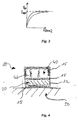
- the spring element 42 of the intermediate layer 40 has asymptotic load vs displacement loading behavior, which can be learned best from the graphic representation of FIG.3 of the drawings. In the graph there is drawn this behavior with two curves comprising different velocities in converging towards a maximum load value F max .
- the asymptotic behavior of the intermediate layer material ensures that the peel strength will not be exceeded. Furthermore, the faster the material reaches the asymptotic value of F max , the more sensitive the load sharing of the bonding arrangement 10 is (lower allowable displacements).
- FIG. 3 of the drawings an example of schematically illustrates the asymptotic load vs. displacement loading behavior of the intermediate layer acting as a spring according to an embodiment of the disclosure by graphic representation with two curves approaching a maximum value of load F with increasing displacement ⁇ in an asymptotic manner.
- FIGS. 4 and 5 it is initially shown a schematic lateral view illustration of the bonding arrangement 10 according to embodiments of the disclosure with the substrate 50 with applied coating structure 20 subdivided into neighboring structural elements 22 and the supporting member 30 provided with several adhesive means in FIG. 4 .
- a substrate 50 of the bonding arrangement 10 of the present disclosure equipped with a coating structure 20.
- the coating structure 20 covers an area of the substrate 50 and is subdivided into hexagonal structural elements 22.
- the structural elements 22 itselves are received in recesses 32 of a supporting member 30, the recesses 32 forming female brackets for the island-like structural elements 22.
- an intermediate layer 40 acting as a spring represented by spring elements 42 arranged in the recesses 32 there is arranged an intermediate layer 40 acting as a spring represented by spring elements 42 arranged in the recesses 32. Furthermore, there are adhesives provided between the supporting member 30 and the structural elements 22 as well as between the structural elements 22 and the substrate 50 to create a tough bonding arrangement 10.
- the supporting member 30 is shown in greater detail in the schematic perspective sectional view of FIG. 5 , where the supporting member 30 is illustrated from the bottom with an installed intermediate layer 40 and the recesses 32 ready to receive the individual structural members 22 of the coating structure 20 according to embodiments of the disclosure.
- the intermediate layer 40 is illustrated with a layer structure 41 as well as a spring element 42 making clear its mechanical properties.
- the hexagonal shape of the recesses 32 reflecting as well the shape of the structural elements 22 (not shown here for sake of clarity) is clearly demonstrated in FIG. 5 .
- a bonding arrangement 10 for the assembly of structures comprising at least one substrate member 50 to which at least one coating structure 20 is applied, the substrate member 50 and the coating structure 20 comprising a common interface which forms at least one bond, the at least one bond being designed as an adhesive bond.
- the coating structure 20 is split into a plurality of neighboring structural elements 22 spatially separated from each other, and at least one supporting member 30 is provided, which comprises a plurality of recesses 32 receiving the structural elements 22 in operating position.
- the terms “comprise”, “comprising”, “include”, “including”, “contain”, “containing”, “have”, “having”, and any variations thereof, are intended to be understood in an inclusive (i.e. non-exclusive) sense, such that the process, method, device, apparatus or system described herein is not limited to those features or parts or elements or steps recited but may include other elements, features, parts or steps not expressly listed or inherent to such process, method, article, or apparatus.
- the terms “a” and “an” used herein are intended to be understood as meaning one or more unless explicitly stated otherwise.
- the terms “first”, “second”, “third”, etc. are used merely as labels, and are not intended to impose numerical requirements on or to establish a certain ranking of importance of their object.
Landscapes
- Engineering & Computer Science (AREA)
- Mechanical Engineering (AREA)
- General Engineering & Computer Science (AREA)
- Adhesives Or Adhesive Processes (AREA)
- Laminated Bodies (AREA)
Abstract
Description
- The invention relates to a bonding arrangement for the assembly of structures, the structures comprising at least one substrate member to which at least one coating structure is applied, the substrate member and the coating structure comprising a common interface which forms at least one bond, the at least one bond being designed as an adhesive bond. The invention also relates to a method of providing such a bonding arrangement for use in an aircraft or spacecraft, as well as to a vehicle, particularly an aircraft or a spacecraft, that incorporates one or more devices comprising an assembled structure with such a bonding arrangement.
- The handling of composite materials comprising polymer matrix composites as fiber-reinforced plastics often raise the question how to join composite structures with other materials as, for example, certain metals or themselves. To join composites or mixed materials, mechanical attachments may be used with the different su rfaces.
- State of the art bonding uses small test specimens produced in the same cycle, with the same materials and by the same operators in order to verify the quality of the bond. This technique is aimed at guaranteeing the strength of the bond.
- Unfortunately, non-destructive testing (NDT) of bond strength is very expensive and time consuming.
- It is therefore an object of the present invention to provide a new and improved bonding arrangement, especially for use in an aircraft or spacecraft. It would be particularly desirable to provide a bonding arrangement that is designed or configured to or create a bond design which is incapable of locally loading the adhesive above the peel strength.
- In accordance with the present invention, a bonding arrangement and a method of forming such a bonding arrangement, as recited in claim 1 and claim 12, respectively, are provided for use particularly in aeronautical applications. Furthermore, in accordance with the invention, a vehicle, such as an aircraft or spacecraft, as recited in
claim 15 is also provided. A number of preferred features of the invention are recited in the dependent claims. - According to one aspect, therefore, the invention provides a bonding arrangement according to the introducing explanations, in which particularly the coating structure is split into a plurality of neighboring structural elements spatially separated from each other, and whereby at least one supporting member is provided, which comprises a plurality of recesses receiving the structural elements in operating position. Thus, as the structural elements of the coating structure are separated from each other, a load exerted on the arrangement in Mode I is spread over the individual structural elements. Accordingly, the invention provides a load sharing arrangement which is incapable of locally loading the adhesive above the peel strength. This effectively removes the weak peeling mode failure from adhesive bonds.
- In a beneficial embodiment of the present invention, the supporting member covers the surfaces of the structural elements facing the recesses thus ensuring a plane reception of the individual structural elements. In a further embodiment, the supporting member forms a sort of a bracket surrounding each of the neighboring structural elements of the coating structure at least in part. Accordingly, the individual structural elements form a kind of "islands" and are covered by a female bracket which has a form fit to the elements. The islands can be installed in the bracket before application to the surface to ensure placement accuracy. An adhesive can be applied to the islands or an appropriately shaped adhesive film. The bond of the supporting member together with the structural elements received in the recesses, the recesses surrounding the structural elements as a form of a female bracket forms itself a kind of a pad.
- In another advantageous embodiment of the present invention, the supporting member and the neighboring structural elements of the coating structure are connected indirectly to enhance the supporting capabilities of the supporting member. A preferred embodiment may therefore comprise an intermediate layer, which is arranged between the supporting member and the neighboring structural elements of the coating structure and which particularly provides the mechanical properties of a spring between the supporting member and the respective neighboring structural element.
- As seen before, the islands formed by the neighboring structural elements are not connected directly to the female bracket of the supporting member. There is an intermediate layer which acts as a spring. Preferably, in another embodiment of the present invention the spring formed by the intermediate layer shows an asymptotic load vs. displacement loading behavior, which means the faster the material reaches the asymptote the more sensitive the load sharing is and consequently the lower are the displacements allowed.
- Due to the characteristics of the material under load, the load on a single structural element, forming one of the mentioned islands, cannot increase above a predetermined level. Due to this characteristic the load is spread around all the other "islands" which are not at maximum load carrying capability. This ensures maximum uniform load distribution before failure.
- The spring (layer) is bonded to the female bracket of the supporting member and to the respective "island". The thickness of the spring layer, the "islands" and adhesives should be minimized to reduce secondary bending.
- In a further embodiment, the material of the intermediate layer may comprise an anisotropic lattice material, which material is especially formed by foam, a super-elastic polymer or a multi-material combination, in each case showing asymptotic spring loading behavior. The respective spring can be manufactured, for example, using additive manufacturing for an anisotropic lattice
- In other advantageous embodiments the material is formed by at least one elastomeric foam, a super-elastic alloy and/or a shape memory alloy, for example a copper-aluminium-nickel (Cu-Al-Ni) alloy, a Nitinol shape memory alloy or a super-elastic polyisoprene-based polymer. Furthermore, it is conceivable that the intermediate layer is formed by any material, which exhibits asymptotic spring loading behavior.
- To ensure a regular and accurate coating of the substrate member and a uniform load distribution in case of Mode I loading if the bonding arrangement, in a further embodiment of the present invention the plurality of first structural elements comprises a regular structure, particularly a periodic structure and/or wherein the periodic structure of the first structural elements forming the mentioned islands is designed such, that the perimeter of the structure is minimized. Therefore, the islands are preferably formed as hexagons.
- In further embodiment of the present invention, having an improved stability between the arrangement members, there is an adhesive means arranged between at least one of the contacting surfaces of the structural elements, the intermediate layer, and the supporting member.
- According to another aspect, the disclosure provides a method of forming a bonding arrangement, with at least one substrate member and one coating structure to be assembled, both comprising a common interface which forms at least one bond, comprising the steps of:
- providing a coating structure and subdividing the coating structure into a plurality of neighboring structural elements spatially separated from each other;
- providing a supporting member with recesses which are designed to receive the neighboring structural elements;
- providing an intermediate layer showing spring properties and securing the layer with its elements in recesses of the supporting member;
- securing the plurality of neighboring structural elements in the recesses of the supporting member;
- preparing surfaces of all parts;
- applying at least one adhesive to the neighboring structural elements.
- In one embodiment, the method according to the present invention further comprises the step of attaching the bonding arrangement to the substrate being the desired surface to fasten the coating structure to the substrate to be covered and /or subsequently followed by a curing step to safely cure the assembly.
- To facilitate the production of bonding arrangements the structural elements of the coating structure and/or the supporting member made available in the production process, according to still another embodiment of the present invention, are advantageously provided using a selective laser melting process or a selective laser sintering process.
- According to still another aspect, the present disclosure also provides a vehicle, such as an aircraft or spacecraft, which incorporates at least one bonding arrangement according to any one of the embodiments of the disclosure described above.
- For a more complete understanding of the invention and the advantages thereof, exemplary embodiments of the invention are explained in more detail in the following description with reference to the accompanying drawings, in which like reference characters designate like parts and in which:
- FIG. 1
- is a schematic illustration of a plane view of individual structural elements of a coating structure received in recesses of a supporting member according to embodiments of the disclosure;
- FIG. 2
- is a schematic perspective view of a plurality of neighboring structural elements each comprising a symbolic spring element illustrating the redundancy of the load sharing of the bonding arrangement according to embodiments of the disclosure;
- FIG: 3
- schematically illustrates the asymptotic load vs. displacement loading behavior of the intermediate layer acting as a spring according to an embodiment of the disclosure by graphic representation;
- FIG. 4
- is a schematic lateral view illustration of the bonding arrangement according to embodiments of the disclosure with the substrate with applied coating structure subdivided into neighboring structural elements and the supporting member provided with several adhesive means; and
- FIG: 5
- is a schematic perspective sectional view from the bottom illustrating the supporting member with installed intermediate layer and the recesses ready to receive the individual structural members of the coating structure according to embodiments of the disclosure.
- The accompanying drawings are included to provide a further understanding of the present disclosure and are incorporated in and constitute a part of this specification. The drawings illustrate particular embodiments of the invention and together with the description serve to explain the principles of the invention. Other embodiments of the invention and many of the attendant advantages of the invention will be readily appreciated as they become better understood with reference to the following detailed description.
- It will be appreciated that common and well understood elements that may be useful or necessary in a commercially feasible embodiment are not necessarily depicted in order to facilitate a more abstracted view of the embodiments. The elements of the drawings are not necessarily illustrated to scale relative to each other. It will further be appreciated that certain actions and/or steps in an embodiment of a method may be described or depicted in a particular order of occurrences while those skilled in the art will understand that such specificity with respect to sequence is not necessarily required. It will also be understood that the terms and expressions used in the present specification have the ordinary meaning as is accorded to such terms and expressions with respect to their corresponding respective areas of inquiry and study, except where specific meanings have otherwise been set forth herein.
- With reference firstly to
FIG. 1 of the drawings, a general structure providing the load sharing concept of a bond arrangement in whole referenced with 10 is illustrated. A plurality of individualstructural elements 22 of acoating structure 20 is shown, thestructural elements 22 are formed as hexagonal "islands. Thestructural elements 22 are received inrecesses 32 of a supportingmember 30 according to embodiments of the disclosure. One can identify the tiling of the neighboringstructural elements 22 as individual hexagonal "islands" which are covered by the recesses each forming a kind of a female bracket which has a form fit to the hexagons. The islands (structural elements 22) can be installed in the bracket before application to the surface of thesubstrate 50 to ensure placement accuracy. An adhesive (not shown inFig.1 ) can be applied to thestructural elements 22 or a hexagonally shaped adhesive film (neither shown). - Referring now to
FIG. 2 of the drawings, a schematic perspective view of a somewhat arbitrarily chosen plurality of neighboringstructural elements 22 of thecoating structure 20 is shown, thestructural elements 22 each comprising asymbolic spring element 42 illustrating the redundancy of the load sharing of the bonding arrangement according to embodiments of the disclosure. The hexagonal islands representing thestructural elements 22 are not connected directly to the associated female bracket of the respective recesses as there is anintermediate layer 40 which acts as a spring (spring element 42). Due to the characteristics of the material under load, the load on a single, pad-likestructural element 22 cannot increase above a predetermined level. Due to this characteristic the load is spread around over all the other "islands" which are not at maximum load carrying capability. This ensures maximum uniform load distribution before failure. - The
spring element 42 of theintermediate layer 40 has asymptotic load vs displacement loading behavior, which can be learned best from the graphic representation ofFIG.3 of the drawings. In the graph there is drawn this behavior with two curves comprising different velocities in converging towards a maximum load value Fmax. The asymptotic behavior of the intermediate layer material ensures that the peel strength will not be exceeded. Furthermore, the faster the material reaches the asymptotic value of Fmax, the more sensitive the load sharing of thebonding arrangement 10 is (lower allowable displacements). - Referring now to
FIG. 3 of the drawings, an example of schematically illustrates the asymptotic load vs. displacement loading behavior of the intermediate layer acting as a spring according to an embodiment of the disclosure by graphic representation with two curves approaching a maximum value of load F with increasing displacement δ in an asymptotic manner. - Now turning to
FIGS. 4 and5 , it is initially shown a schematic lateral view illustration of thebonding arrangement 10 according to embodiments of the disclosure with thesubstrate 50 with appliedcoating structure 20 subdivided into neighboringstructural elements 22 and the supportingmember 30 provided with several adhesive means inFIG. 4 . At the bottom ofFIG.4 , one finds asubstrate 50 of thebonding arrangement 10 of the present disclosure equipped with acoating structure 20. Thecoating structure 20 covers an area of thesubstrate 50 and is subdivided into hexagonalstructural elements 22. Thestructural elements 22 itselves are received inrecesses 32 of a supportingmember 30, therecesses 32 forming female brackets for the island-likestructural elements 22. Between thecoating structure 20 with thestructural elements 22 and the supportingmember 30 with itsrecesses 32 there is arranged anintermediate layer 40 acting as a spring represented byspring elements 42 arranged in therecesses 32. Furthermore, there are adhesives provided between the supportingmember 30 and thestructural elements 22 as well as between thestructural elements 22 and thesubstrate 50 to create atough bonding arrangement 10. - The supporting
member 30 is shown in greater detail in the schematic perspective sectional view ofFIG. 5 , where the supportingmember 30 is illustrated from the bottom with an installedintermediate layer 40 and therecesses 32 ready to receive the individualstructural members 22 of thecoating structure 20 according to embodiments of the disclosure. To simplify matters and to clarify one of the concepts of the present invention, theintermediate layer 40 is illustrated with a layer structure 41 as well as aspring element 42 making clear its mechanical properties. Moreover, the hexagonal shape of therecesses 32 reflecting as well the shape of the structural elements 22 (not shown here for sake of clarity) is clearly demonstrated inFIG. 5 . - To conclude, according to the above explanations a
bonding arrangement 10 for the assembly of structures is disclosed, the structures comprising at least onesubstrate member 50 to which at least onecoating structure 20 is applied, thesubstrate member 50 and thecoating structure 20 comprising a common interface which forms at least one bond, the at least one bond being designed as an adhesive bond. Thecoating structure 20 is split into a plurality of neighboringstructural elements 22 spatially separated from each other, and at least one supportingmember 30 is provided, which comprises a plurality ofrecesses 32 receiving thestructural elements 22 in operating position. - Thus, with the present disclosure a structural design concept is provided, which uniformly spreads all peel loads due to asymptotic spring-displacement behavior of an intermediate interface. This gives the opportunity to remove Mode I failure from bonded joints. Consequently, local bonding defects (weak bonds) have a decreasing impact on bond strength as the number of islands (structural elements 22) goes up leading to negligible influence at high number of islands, in other words, a higher degree of redundancy is provided.
- Although specific embodiments of the invention have been illustrated and described herein, it will be appreciated by those of ordinary skill in the art that a variety of alternate and/or equivalent implementations exist. It should be appreciated that the exemplary embodiment or exemplary embodiments are only examples, and are not intended to limit the scope, applicability, or configuration in any way. Rather, the foregoing summary and detailed description will provide those skilled in the art with a convenient road map for implementing at least one exemplary embodiment, it being understood that various changes may be made in the function and arrangement of elements described in an exemplary embodiment without departing from the scope as set forth in the appended claims and their legal equivalents. Generally, this application is intended to cover any adaptations or variations of the specific embodiments discussed herein.
- In this document, the terms "comprise", "comprising", "include", "including", "contain", "containing", "have", "having", and any variations thereof, are intended to be understood in an inclusive (i.e. non-exclusive) sense, such that the process, method, device, apparatus or system described herein is not limited to those features or parts or elements or steps recited but may include other elements, features, parts or steps not expressly listed or inherent to such process, method, article, or apparatus. Furthermore, the terms "a" and "an" used herein are intended to be understood as meaning one or more unless explicitly stated otherwise. Moreover, the terms "first", "second", "third", etc. are used merely as labels, and are not intended to impose numerical requirements on or to establish a certain ranking of importance of their object.
-
- 10
- bonding arrangement
- 15
- adhesive means
- 20
- coating structure
- 22
- structural element
- 30
- supporting member
- 32
- recess
- 40
- intermediate layer
- 42
- spring element
- 50
- su bstrate
Claims (15)
- A bonding arrangement (10) for the assembly of structures, the structures comprising at least one substrate member (50) to which at least one coating structure (20) is applied, the substrate member (50) and the coating structure (20) comprising a common interface which forms at least one bond, the at least one bond being designed as an adhesive bond, wherein the coating structure (20) is split into a plurality of neighboring structural elements (22) spatially separated from each other, and wherein at least one supporting member (30) is provided, which comprises a plurality of recesses (32) receiving the structural elements (22) in operating position.
- Bonding arrangement according to claim 1, wherein the supporting member (30) covers the surfaces of the neighboring structural elements (22) facing the recesses (32).
- Bonding arrangement according to claim 1 or 2, wherein the supporting member (30) forms a sort of a bracket surrounding each of the neighboring structural elements (22) of the coating structure (20) at least in part.
- Bonding arrangement according to at least one of the preceding claims, wherein the supporting member (30) and the neighboring structural elements (22) of the coating structure (20) are connected indirectly.
- Bonding arrangement according to at least one of the preceding claims, wherein an intermediate layer (40) is arranged between the supporting member (30) and the neighboring structural elements (22) of the coating structure (32).
- Bonding arrangement according to claim 5, wherein the intermediate layer (40) provides the mechanical properties of a spring between the supporting member (30) and the respective neighboring structural element (22).
- Bonding arrangement according to claim 6, wherein the spring (42) formed by the intermediate (40) layer shows an asymptotic load vs. displacement loading behavior.
- Bonding arrangement according to at least one of the claims 5 to 7, wherein the intermediate layer (40) comprises an anisotropic lattice material, which is especially formed by a foam, a super-elastic polymer or a multi-material combination, each showing asymptotic spring loading behavior.
- Bonding arrangement according to claim 8, wherein the material is formed by at least one elastomeric foam, by a super-elastic alloy and/or a shape memory alloy, for example a copper-aluminium-nickel (CuAlNi) alloy, a Nitinol shape memory alloy or a super-elastic polyisoprene-based polymer.
- Bonding arrangement according to at least one of the preceding claims, wherein the plurality of first structural elements (22) comprises a regular structure, particularly a periodic structure and/or whereby the periodic structure of the first structural elements (22) is designed such, that the perimeter of the structure is minimized.
- Bonding arrangement according to at least one of the preceding claims, wherein between contacting surfaces of at least two of the structural elements, the intermediate layer, and the supporting member an adhesive means (15) is arranged.
- Production method for a bonding arrangement (10), particularly a bonding arrangement (10) according to at least one of the preceding claims, with at least one substrate member (50) and one coating structure (20) to be assembled, both comprising a common interface which forms at least one bond, comprising the following steps:providing a coating structure (20) and subdividing the coating structure (20) into a plurality of neighboring structural elements (22) spatially separated from each other;providing a supporting member (30) with recesses which are designed to receive the neighboring structural elements (22);providing an intermediate layer (40) showing spring properties and securing the layer (40) with its elements in recesses (32) of the supporting member (30);securing the plurality of neighboring structural elements (22) in the recesses (32) of the supporting member (30);preparing surfaces of all parts; andapplying adhesive (15) to the neighboring structural elements (22);
- Method according to claim 12, further comprising the step of attaching the bonding arrangement (10) to the substrate (50) and/or curing of the assembly.
- Method according to claim 13 or 14, wherein the structural elements (22) of the coating structure (20) are provided using a selective laser melting process or a selective laser sintering process.
- Vehicle, particularly aircraft or spacecraft provided with at least one device comprising an assembled structure with a bonding arrangement (10) according to one of the claims 1 to 11 or produced according to a method according to one of the claims 12 to 14.
Priority Applications (2)
| Application Number | Priority Date | Filing Date | Title |
|---|---|---|---|
| EP16189841.6A EP3299160A1 (en) | 2016-09-21 | 2016-09-21 | Bonding arrangement and assigned production method |
| US15/706,919 US10479048B2 (en) | 2016-09-21 | 2017-09-18 | Bonding arrangement and production method |
Applications Claiming Priority (1)
| Application Number | Priority Date | Filing Date | Title |
|---|---|---|---|
| EP16189841.6A EP3299160A1 (en) | 2016-09-21 | 2016-09-21 | Bonding arrangement and assigned production method |
Publications (1)
| Publication Number | Publication Date |
|---|---|
| EP3299160A1 true EP3299160A1 (en) | 2018-03-28 |
Family
ID=57218665
Family Applications (1)
| Application Number | Title | Priority Date | Filing Date |
|---|---|---|---|
| EP16189841.6A Withdrawn EP3299160A1 (en) | 2016-09-21 | 2016-09-21 | Bonding arrangement and assigned production method |
Country Status (2)
| Country | Link |
|---|---|
| US (1) | US10479048B2 (en) |
| EP (1) | EP3299160A1 (en) |
Citations (7)
| Publication number | Priority date | Publication date | Assignee | Title |
|---|---|---|---|---|
| US6558222B1 (en) * | 1997-02-28 | 2003-05-06 | Paul Thomas Maddock | Panelling and supports for interconnected toy blocks |
| DE202007008330U1 (en) * | 2007-06-14 | 2007-09-13 | Syrbe, Alexandra | Cover or cover for flat objects, such as books, brochures, magazines or toys in book form |
| EP2415601A2 (en) * | 2010-08-05 | 2012-02-08 | Alfred Waas | Method and device for producing a sandwich board and core layer for a sandwich board |
| US20130087273A1 (en) * | 2010-03-23 | 2013-04-11 | Airbus Operations Gmbh | Stiffening component and method as well as combing tool |
| WO2014082867A1 (en) * | 2012-11-28 | 2014-06-05 | Tesa Se | Transparent security film |
| US20140220854A1 (en) * | 2013-02-07 | 2014-08-07 | Yang-Chih Lee | Adaptor brick |
| US20150086824A1 (en) * | 2011-08-03 | 2015-03-26 | Oswaldo Nicolas Burga | Undrainable battery power system of interlocking lego-like interconnectable pluggable interchangeable inter-rechargeable batteries |
Family Cites Families (2)
| Publication number | Priority date | Publication date | Assignee | Title |
|---|---|---|---|---|
| DE9408914U1 (en) * | 1994-05-31 | 1994-09-29 | Chicony Electronics Co., Ltd., Taipeh/T'ai-pei | Key switch |
| GB0205164D0 (en) * | 2002-03-06 | 2002-04-17 | Bennett Nicholas R | Improvements to key pad keys (2) |
-
2016
- 2016-09-21 EP EP16189841.6A patent/EP3299160A1/en not_active Withdrawn
-
2017
- 2017-09-18 US US15/706,919 patent/US10479048B2/en active Active
Patent Citations (7)
| Publication number | Priority date | Publication date | Assignee | Title |
|---|---|---|---|---|
| US6558222B1 (en) * | 1997-02-28 | 2003-05-06 | Paul Thomas Maddock | Panelling and supports for interconnected toy blocks |
| DE202007008330U1 (en) * | 2007-06-14 | 2007-09-13 | Syrbe, Alexandra | Cover or cover for flat objects, such as books, brochures, magazines or toys in book form |
| US20130087273A1 (en) * | 2010-03-23 | 2013-04-11 | Airbus Operations Gmbh | Stiffening component and method as well as combing tool |
| EP2415601A2 (en) * | 2010-08-05 | 2012-02-08 | Alfred Waas | Method and device for producing a sandwich board and core layer for a sandwich board |
| US20150086824A1 (en) * | 2011-08-03 | 2015-03-26 | Oswaldo Nicolas Burga | Undrainable battery power system of interlocking lego-like interconnectable pluggable interchangeable inter-rechargeable batteries |
| WO2014082867A1 (en) * | 2012-11-28 | 2014-06-05 | Tesa Se | Transparent security film |
| US20140220854A1 (en) * | 2013-02-07 | 2014-08-07 | Yang-Chih Lee | Adaptor brick |
Also Published As
| Publication number | Publication date |
|---|---|
| US10479048B2 (en) | 2019-11-19 |
| US20180079171A1 (en) | 2018-03-22 |
Similar Documents
| Publication | Publication Date | Title |
|---|---|---|
| KR101739148B1 (en) | Rigid tipped riblets | |
| US9823143B2 (en) | Additively grown enhanced impact resistance features for improved structure and joint protection | |
| US20120286091A1 (en) | Composite Aircraft Joint | |
| CN103391840B (en) | For aircraft or the connector of spacecraft and the manufacture method of connector | |
| US11458704B2 (en) | Carrier film for transferring microelement | |
| US7998389B2 (en) | Method for septumizing injection molded thermoplastic core | |
| KR101755483B1 (en) | Adhering structure of different kinds of materials | |
| EP3268622B1 (en) | Thermally activated, shape configuable mechanical locking z-pin | |
| US10549483B2 (en) | Surfaces with tunable adhesion based on composite structures and methods of making the same | |
| EP4129635B1 (en) | Method of manufacturing adhered components | |
| US10479048B2 (en) | Bonding arrangement and production method | |
| JP2016039343A (en) | Electronic device and manufacturing method of the same | |
| US20200023628A1 (en) | Methods for fast and reversible dry adhesion tuning between composite structures and substrates using dynamically tunable stiffness | |
| US8455085B2 (en) | Metal/composite joint with selective interlaminar reinforcement | |
| CN106590451A (en) | Combination gluing comprising permanent gluing and temporary gluing for facilitating and accelerating production | |
| CN105873757A (en) | Bonded assembly provided with an intermediate deformation layer with variable flexibility | |
| US10464281B2 (en) | Sandwich composite with shape memory alloy core and method of making same | |
| WO2008023012A1 (en) | Assembly, optical system and method for producing an assembly | |
| CN114270508A (en) | Method and system for stretching a receptor substrate to adjust placement of components | |
| CN113851441A (en) | Attachment system and method for attaching a sensor to a substrate | |
| US20140252362A1 (en) | Thin film apparatus | |
| WO2021122660A1 (en) | Intermediate deformation layer with adjustable macroscopic stiffness for bonded assembly | |
| EP2781345B1 (en) | Method and system for producing composite structures | |
| KR20190066340A (en) | Repair fastener for composite materials delamination and the methods using the device | |
| Schubert et al. | Advanced micro structuring and joining technologies for direct integration of piezo fibers into metallic materials |
Legal Events
| Date | Code | Title | Description |
|---|---|---|---|
| PUAI | Public reference made under article 153(3) epc to a published international application that has entered the european phase |
Free format text: ORIGINAL CODE: 0009012 |
|
| STAA | Information on the status of an ep patent application or granted ep patent |
Free format text: STATUS: THE APPLICATION HAS BEEN PUBLISHED |
|
| AK | Designated contracting states |
Kind code of ref document: A1 Designated state(s): AL AT BE BG CH CY CZ DE DK EE ES FI FR GB GR HR HU IE IS IT LI LT LU LV MC MK MT NL NO PL PT RO RS SE SI SK SM TR |
|
| AX | Request for extension of the european patent |
Extension state: BA ME |
|
| STAA | Information on the status of an ep patent application or granted ep patent |
Free format text: STATUS: REQUEST FOR EXAMINATION WAS MADE |
|
| STAA | Information on the status of an ep patent application or granted ep patent |
Free format text: STATUS: EXAMINATION IS IN PROGRESS |
|
| 17P | Request for examination filed |
Effective date: 20180925 |
|
| RBV | Designated contracting states (corrected) |
Designated state(s): AL AT BE BG CH CY CZ DE DK EE ES FI FR GB GR HR HU IE IS IT LI LT LU LV MC MK MT NL NO PL PT RO RS SE SI SK SM TR |
|
| 17Q | First examination report despatched |
Effective date: 20181018 |
|
| STAA | Information on the status of an ep patent application or granted ep patent |
Free format text: STATUS: THE APPLICATION IS DEEMED TO BE WITHDRAWN |
|
| 18D | Application deemed to be withdrawn |
Effective date: 20221011 |