EP3298819B1 - Attention (at) commands for packet data network connection offload - Google Patents
Attention (at) commands for packet data network connection offload Download PDFInfo
- Publication number
- EP3298819B1 EP3298819B1 EP15892784.8A EP15892784A EP3298819B1 EP 3298819 B1 EP3298819 B1 EP 3298819B1 EP 15892784 A EP15892784 A EP 15892784A EP 3298819 B1 EP3298819 B1 EP 3298819B1
- Authority
- EP
- European Patent Office
- Prior art keywords
- command
- network
- context
- wlan
- circuitry
- Prior art date
- Legal status (The legal status is an assumption and is not a legal conclusion. Google has not performed a legal analysis and makes no representation as to the accuracy of the status listed.)
- Active
Links
Images





Classifications
-
- H—ELECTRICITY
- H04—ELECTRIC COMMUNICATION TECHNIQUE
- H04W—WIRELESS COMMUNICATION NETWORKS
- H04W76/00—Connection management
- H04W76/10—Connection setup
- H04W76/12—Setup of transport tunnels
-
- H—ELECTRICITY
- H04—ELECTRIC COMMUNICATION TECHNIQUE
- H04L—TRANSMISSION OF DIGITAL INFORMATION, e.g. TELEGRAPHIC COMMUNICATION
- H04L47/00—Traffic control in data switching networks
- H04L47/10—Flow control; Congestion control
- H04L47/29—Flow control; Congestion control using a combination of thresholds
-
- H—ELECTRICITY
- H04—ELECTRIC COMMUNICATION TECHNIQUE
- H04W—WIRELESS COMMUNICATION NETWORKS
- H04W28/00—Network traffic management; Network resource management
- H04W28/02—Traffic management, e.g. flow control or congestion control
- H04W28/10—Flow control between communication endpoints
- H04W28/12—Flow control between communication endpoints using signalling between network elements
-
- H—ELECTRICITY
- H04—ELECTRIC COMMUNICATION TECHNIQUE
- H04W—WIRELESS COMMUNICATION NETWORKS
- H04W36/00—Hand-off or reselection arrangements
- H04W36/0005—Control or signalling for completing the hand-off
- H04W36/0011—Control or signalling for completing the hand-off for data sessions of end-to-end connection
- H04W36/0016—Hand-off preparation specially adapted for end-to-end data sessions
-
- H—ELECTRICITY
- H04—ELECTRIC COMMUNICATION TECHNIQUE
- H04W—WIRELESS COMMUNICATION NETWORKS
- H04W36/00—Hand-off or reselection arrangements
- H04W36/16—Performing reselection for specific purposes
- H04W36/22—Performing reselection for specific purposes for handling the traffic
-
- H—ELECTRICITY
- H04—ELECTRIC COMMUNICATION TECHNIQUE
- H04W—WIRELESS COMMUNICATION NETWORKS
- H04W36/00—Hand-off or reselection arrangements
- H04W36/24—Reselection being triggered by specific parameters
-
- H—ELECTRICITY
- H04—ELECTRIC COMMUNICATION TECHNIQUE
- H04W—WIRELESS COMMUNICATION NETWORKS
- H04W36/00—Hand-off or reselection arrangements
- H04W36/34—Reselection control
- H04W36/36—Reselection control by user or terminal equipment
-
- H—ELECTRICITY
- H04—ELECTRIC COMMUNICATION TECHNIQUE
- H04W—WIRELESS COMMUNICATION NETWORKS
- H04W72/00—Local resource management
- H04W72/12—Wireless traffic scheduling
-
- H—ELECTRICITY
- H04—ELECTRIC COMMUNICATION TECHNIQUE
- H04W—WIRELESS COMMUNICATION NETWORKS
- H04W76/00—Connection management
- H04W76/10—Connection setup
- H04W76/15—Setup of multiple wireless link connections
- H04W76/16—Involving different core network technologies, e.g. a packet-switched [PS] bearer in combination with a circuit-switched [CS] bearer
-
- H—ELECTRICITY
- H04—ELECTRIC COMMUNICATION TECHNIQUE
- H04W—WIRELESS COMMUNICATION NETWORKS
- H04W84/00—Network topologies
- H04W84/02—Hierarchically pre-organised networks, e.g. paging networks, cellular networks, WLAN [Wireless Local Area Network] or WLL [Wireless Local Loop]
- H04W84/10—Small scale networks; Flat hierarchical networks
- H04W84/12—WLAN [Wireless Local Area Networks]
-
- H—ELECTRICITY
- H04—ELECTRIC COMMUNICATION TECHNIQUE
- H04W—WIRELESS COMMUNICATION NETWORKS
- H04W88/00—Devices specially adapted for wireless communication networks, e.g. terminals, base stations or access point devices
- H04W88/02—Terminal devices
- H04W88/06—Terminal devices adapted for operation in multiple networks or having at least two operational modes, e.g. multi-mode terminals
-
- H—ELECTRICITY
- H04—ELECTRIC COMMUNICATION TECHNIQUE
- H04W—WIRELESS COMMUNICATION NETWORKS
- H04W36/00—Hand-off or reselection arrangements
- H04W36/0005—Control or signalling for completing the hand-off
- H04W36/0011—Control or signalling for completing the hand-off for data sessions of end-to-end connection
- H04W36/0033—Control or signalling for completing the hand-off for data sessions of end-to-end connection with transfer of context information
Definitions
- Embodiments pertain to wireless communications, in particular to communication signals between user equipment (UE) components.
- UE user equipment
- WO 2013/025192 A1 relates to a method for a User Equipment (UE).
- the method includes responsive, at least in part, to an ATtention (AT) command for touch-sensitive display action, emulating or reporting a meta-navigation gesture for a touch-sensitive input including a display area and a non-display area.
- AT ATtention
- 3GPP TS 27.007 "AT command set for User Equipment (UE) (Release 13)", Version 13.0.0, March 2015 , specifies a profile of AT commands and recommends that this profile be used for controlling Mobile Termination (MT) functions and GSM/UMTS network services from a Terminal Equipment (TE) through Terminal Adaptor (TA).
- UE User Equipment
- TA Terminal Adaptor
- the UE 102 can be configured to communicate using Orthogonal Frequency-Division Multiplexing (OFDM) communication signals with any of the eNodeBs 212 over a multicarrier communication channel in accordance with various communication techniques, such as an Orthogonal Frequency-Division Multiple Access (OFDMA) communication technique or a Single Carrier Frequency Division Multiple Access (SC-FDMA) communication technique, although the scope of the embodiments is not limited in this respect.
- OFDM signals can comprise a plurality of orthogonal subcarriers.
- the UE 102 can be configured to determine a synchronization reference time based on reception of one or more signals from any of the eNodeBs 212.
- the UE 102 can also be configured to support device-to-device (D2D) or proximity-based services (ProSE) communication with other UEs using OFDMA, SC-FDMA, or other multiple access schemes.
- D2D device-to-device
- ProSE proximity-based services
- an LP eNodeB can be implemented with a picocell eNodeB since it is coupled to a macro eNodeB via an X2 interface.
- Picocell eNodeBs or other LP eNodeBs can incorporate some or all functionality of a macro eNodeB.
- a picocell eNodeB can be referred to as an access point base station (AP BS) or enterprise femtocell.
- AP BS access point base station
- enterprise femtocell enterprise femtocell
- a radio resource control (RRC) state indicates whether an RRC layer of the UE 102 is logically connected to an RRC layer of the E-UTRAN 210.
- RRC radio resource control
- RRC_CONNECTED When the UE 102 has data packets to transmit or receive, its RRC state becomes RRC_CONNECTED.
- the UE 102 when in an RRC_IDLE state, can associate itself to different cells.
- a downlink resource grid can be used for downlink transmissions from any of the eNodeBs 212 to the UE 102, while uplink transmission from the UE 102 to any of the eNodeBs 212 can utilize similar techniques.
- the grid can be a time-frequency grid, called a resource grid or time-frequency resource grid, which is the physical resource in the downlink in each slot.
- a time-frequency plane representation is a common practice for OFDM systems, which makes it intuitive for radio resource allocation.
- Each column and each row of the resource grid corresponds to one OFDM symbol and one OFDM subcarrier, respectively.
- the duration of the resource grid in the time domain corresponds to one slot in a radio frame.
- Each resource grid comprises a number of resource blocks, which describe the mapping of certain physical channels to resource elements.
- Each resource block comprises a collection of resource elements; in the frequency domain, this represents the smallest quantity of resources that currently can be allocated.
- the synthesizer circuitry 306d may be a fractional-N synthesizer or a fractional N/N+1 synthesizer, although the scope of the embodiments is not limited in this respect as other types of frequency synthesizers may be suitable.
- synthesizer circuitry 306d may be a delta-sigma synthesizer, a frequency multiplier, or a synthesizer comprising a phase-locked loop with a frequency divider.
- the synthesizer circuitry 306d may be configured to synthesize an output frequency for use by the mixer circuitry 306a of the RF circuitry 306 based on a frequency input and a divider control input. In some embodiments, the synthesizer circuitry 306d may be a fractional N/N+1 synthesizer.
- FIG. 4A is an illustration of a UE device as mobile termination (MT) and terminal equipment (TE) functional blocks in accordance with the present invention.
- a UE 400 is illustrated as including a TE 402 and an MT 404 communicatively coupled via a terminal adaptor (TA) 406.
- the TE 402 includes application circuitry (e.g., the application circuitry 302 of the UE 300 of FIG. 3 ) and the MT 404 includes baseband circuitry (e.g., the baseband circuitry 304 of the UE 300 of FIG. 3 ).
- the abstract architecture of UE 400 can be physically implemented in various ways.
- the TE 402, the MT 404, and the TA 406 are implemented as three separate entities.
- the TA 406 is integrated under the MT 404 cover, and the TE 402 is implemented as a separate entity.
- the TA 406 is integrated under the TE 402 cover, and the MT 404 is implemented as a separate entity.
- the TA 406 and the MT 404 are integrated under the TE 402 cover as a single entity.
- the MT 404 may transmit and receive signal data to and from the one or more networks 412 (shown as operations 454 and 461, respectively), including non-access stratum (NAS) messages for establishing PDN connections and maintaining PDN connections as the UE 400 moves.
- the MT 404 can send MT status messages to the TA 406 (shown as operation 462), which the TA 406 sends to the TE 402 as responses to the AT commands (shown as operation 463). Data from these responses may then be transmitted to the one or more applications 410 (shown as operation 464).
- NAS non-access stratum
- underline Underlined defined subparameter value is the recommended default setting of this subparameter.
- this value should be used in factory settings which may be configured, for example, by ITU-T Recommendation V.250: "Serial asynchronous automatic dialing and control.”
- action type commands this value should be used when subparameter is not given.
- set command enables or disables sending of unsolicited result codes, +CGEV : XXX from MT to TE in the case of certain events occurring in the Packet Domain MT or the network.
- ⁇ mode> controls the processing of unsolicited result codes specified within this command.
- ⁇ bfr> controls the effect on buffered codes when ⁇ mode> 1 or 2 is entered. If a setting is not supported by the MT, ERROR or +CME ERROR: is returned.
- Refer subclause 9.2 for possible ⁇ err> values may comprise, for example, values defined in subclause 9.2 of 3GPP TS 27.007 "AT Command set for User Equipment (UE) .”
- Read command returns the current mode and buffer settings Test command returns the modes and buffer settings supported by the MT as compound values.
- the above fields may describe, for example, a bearer identification associated with the Primary PDP context, an access point name associated with the Primary PDP context, a local address and subnet mask associated with the Primary PDP context, a gateway address associated with the Primary PDP Context, primary or secondary domain name system (DNS) Server address associated with the primary context, primary or secondary proxy-call session control function (P-CSCF) Server address associated with the Primary PDP context, an IP Multimedia Core Network (IM_CN) flag associated with the Primary PDP context identifying the PDN connection as a multimedia PDN Connection, a local IP access (LIPA) indicator associated with the Primary PDP context, an IP maximum transmission unit (MTU) defining a maximum packet size for the primary PDP Context, or data indicating whether the PDN connection associated with a Primary PDP context can be offloaded from the cellular network to the non-cellular network.
- IM_CN IP Multimedia Core Network
- LIPA local IP access
- MTU IP maximum transmission unit
- the test command returns a list of ⁇ cid>s associated with active non secondary contexts.
- the test command returns a list of ⁇ cid>s associated with active secondary PDP contexts.
- Test command returns the values supported by MT as compound values.
- Test command returns the values supported by MT as compound values.
- the UE 600 and eNodeB 650 are each illustrated as having several separate functional elements, one or more of the functional elements can be combined and can be implemented by combinations of software-configured elements, such as processing elements including digital signal processors (DSPs), and/or other hardware elements.
- DSPs digital signal processors
- some elements can comprise one or more microprocessors, DSPs, field-programmable gate arrays (FPGAs), application specific integrated circuits (ASICs), radiofrequency integrated circuits (RFICs), and combinations of various hardware and circuitry for performing at least the functions described herein.
- the functional elements can refer to one or more processes operating on one or more processing elements.
- the example computer system 700 includes a processor 702 (e.g., a central processing unit (CPU), a graphics processing unit (GPU), or both), a main memory 704, and a static memory 706, which communicate with each other via a bus 708.
- the computer system 700 can further include a video display unit 710 (e.g., an LCD or a cathode ray tube (CRT)).
- the computer system 700 also includes an alphanumeric input device 712 (e.g., a keyboard), a user interface navigation (or cursor control) device 714 (e.g., a mouse), a storage device 716, a signal generation device 718 (e.g., a speaker), and a network interface device 720.
- the storage device 716 includes a non-transitory machine-readable medium 722 on which is stored one or more sets of data structures and software 724 embodying or utilized by any one or more of the methodologies or functions described herein.
- the software 724 can also reside, completely or at least partially, within the main memory 704 and/or within the processor 702 during execution thereof by the computer system 700, with the main memory 704 and the processor 702 also constituting non-transitory machine-readable media 722.
- the software 724 can also reside, completely or at least partially, within the static memory 706.
- machine-readable medium 722 is shown, in an example embodiment, to be a single medium, the term “machine-readable medium” can include a single medium or multiple media (e.g., a centralized or distributed database, and/or associated caches and servers) that store the one or more data structures and software 724.
- the term “machine-readable medium” can also be taken to include any tangible medium that is capable of storing, encoding, or carrying instructions for execution by the machine and that cause the machine to perform any one or more of the methodologies of the present embodiments, or that is capable of storing, encoding, or carrying data structures utilized by or associated with such instructions.
Landscapes
- Engineering & Computer Science (AREA)
- Computer Networks & Wireless Communication (AREA)
- Signal Processing (AREA)
- Mobile Radio Communication Systems (AREA)
- Telephone Function (AREA)
Description
- Embodiments pertain to wireless communications, in particular to communication signals between user equipment (UE) components.
- Wireless mobile devices or user equipments (UEs) may communicate with each other via cellular networks using radio access technologies such as the 3GPP Long-Term Evolution ("LTE") standard, 3GPP LTE Advanced Release 12 (March 2014) (the "LTE-A Standard"), the IEEE 802.16 standard, IEEE Std. 802.16-2009, published May 29, 2009 ("WiMAX"), as well as any other wireless protocols that are designated as 3G, 4G, 5G, and beyond. User equipments (UEs) can be configured to connect to one or more cellular networks and one or more non-cellular networks, such as wireless local area networks (WLANs).
-
WO 2012/044085 A2 relates to an apparatus that includes a Mobile Termination (MT) that offers functions related to communication with a network, a Terminal Equipment (TE) that offers services to a user of the apparatus, and a Terminal Adaptor (TA) that allows communication between the MT and the TE using Attention (AT) commands. A packet domain event reporting command (+CGEREP) is one type of AT command that enables or disables sending of result codes from the MT to the TE in case certain events occur in the MT for a packet domain or in the network. One such type of event is a Packet Data Protocol (PDP) context activation, for which the MT sends to the TE a result code that includes an integer type parameter to indicate the reason why a context activation request with PDP type IPv4v6 was not granted, and a context id parameter to indicate the capability of Mobile Termination for autonomously requesting a second address bearer, and the result of the second address bearer activation. -
WO 2013/025192 A1 relates to a method for a User Equipment (UE). The method includes responsive, at least in part, to an ATtention (AT) command for touch-sensitive display action, emulating or reporting a meta-navigation gesture for a touch-sensitive input including a display area and a non-display area. - 3GPP TS 27.007, "AT command set for User Equipment (UE) (Release 13)", Version 13.0.0, March 2015, specifies a profile of AT commands and recommends that this profile be used for controlling Mobile Termination (MT) functions and GSM/UMTS network services from a Terminal Equipment (TE) through Terminal Adaptor (TA).
- The invention is defined by the independent claims. Advantageous embodiments are subject to the dependent claims.
-
-
FIG. 1 illustrates an architecture of a wireless network with various components of the network in accordance with some embodiments. -
FIG. 2 illustrates an architecture of components of an LTE network in accordance with some embodiments. -
FIG. 3 illustrates example components of a user equipment device in accordance with some embodiments. -
FIG. 4A is an illustration of a user equipment device as mobile termination and terminal equipment functional blocks in accordance with some embodiments. -
FIG. 4B illustrates a flow diagram of a process for a mobile termination and a terminal equipment of a user equipment device to exchange information in accordance with some embodiments. -
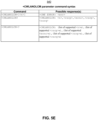
FIG. 5A - FIG. 5E illustrate command/response tables for attention commands in accordance with some embodiments. -
FIG. 6 illustrates a block diagram of a user equipment device and an eNodeB in accordance with some embodiments. -
FIG. 7 illustrates a block diagram illustrating components of a machine, according to some example embodiments, able to read instructions from a machine-readable medium and perform any one or more of the methodologies discussed herein, according to aspects of the disclosure. - The following description and the drawings sufficiently illustrate specific embodiments to enable those skilled in the art to practice them. Other embodiments can incorporate structural, logical, electrical, process, and other changes. Portions and features of some embodiments can be included in, or substituted for, those of other embodiments.
- In some embodiments, mobile devices or other devices described herein can be part of a portable wireless communication device, such as a personal digital assistant (PDA), a laptop or portable computer with wireless communication capability, a web tablet, a wireless telephone, a smartphone, a wireless headset, a pager, a wearable mobile computing device (e.g., a mobile computing device included in a wearable housing), an instant messaging device, a digital camera, an access point, a television, a medical device (e.g., a heart rate monitor, a blood pressure monitor, etc.), or another device that can receive and/or transmit information wirelessly. In some embodiments, the mobile device or other device can be a user equipment (UE) or an evolved node-B (eNodeB) configured to operate in accordance with 3GPP standards (e.g., the 3 GPP Long Term Evolution ("LTE") Advanced Release 12 (March 2014) (the "LTE-A Standard")). In some embodiments, the mobile device or other device can be configured to operate according to other protocols or standards, including IEEE 802.1 1 or other IEEE and 3GPP standards. In some embodiments, the mobile device or other device can include one or more of a keyboard, a display, a non-volatile memory port, multiple antennas, a graphics processor, an application processor, speakers, and other mobile device elements. The display can be a liquid crystal display (LCD) screen including a touch screen.
-
FIG. 1 illustrates an architecture of a wireless network with various components of the network in accordance with some embodiments. Asystem 100 is shown to include a user equipment (UE) 102 and a UE 104. The UEs 102 and 104 are illustrated as smartphones (i.e., handheld touchscreen mobile computing devices connectable to one or more cellular networks), but can also include personal digital assistants (PDAs), pagers, laptop computers, desktop computers, a machine-to-machine (M2M) device, an internet of things (IoT) device, etc. - The UEs 102 and 104 are configured to access a radio access network (RAN) 106 via
connections connections - The RAN 106 can include one or more access points that enable the
connections core network 110. Thecore network 110 can be used to enable a packet-switched data exchange with the Internet 112 in addition to bridging circuit-switched calls between the UEs 102 and 104. In some embodiments, the RAN 106 can comprise an Evolved Universal Mobile Telecommunications System (UMTS) Terrestrial RAN (E-UTRAN 210), and thecore network 110 can comprise an Evolved Packet Core (EPC) network. - The UE 104 is shown to be configured to access an access point (AP) 108 via a
connection 124. Theconnection 124 can comprise a local wireless connection, such as a connection consistent with IEEE 802.11, wherein the AP 108 would comprise a wireless fidelity (WiFi) router. In this example, the AP 108 is shown to be connected to the Internet 112 without connecting to thecore network 110. - The Internet 112 is shown to be communicatively coupled to an
application server 116. Theapplication server 116 can be implemented as a plurality of structurally separate servers, or can be included in a single server. Theapplication server 116 is shown as connected to both the Internet 112 and thecore network 110; in other embodiments, thecore network 110 connects to theapplication server 116 via the Internet 112. Theapplication server 116 can also be configured to support one or more communication services (e.g., Voice-over-Internet Protocol (VoIP) sessions, Push-to-Talk (PTT) sessions, group communication sessions, social networking services, etc.) for UEs that can connect to theapplication server 116 via thecore network 110 and/or the Internet 112. Theapplication server 116 can also be configured as a cloud services provider (CSP) for cellular Internet of Things (CIoT) UEs, as described in further detail below. - The
core network 110 is further shown to be communicatively coupled to an Internet Protocol (IP) Multimedia Subsystem (IMS) 114. The IMS 114 comprises an integrated network of telecommunications carriers that can enable the use of IP for packet communications, such as traditional telephony, fax, e-mail, internet access, Voice over IP (VoIP), instant messaging (IM), videoconference sessions and video on demand (VoD), etc. -
FIG. 2 illustrates an architecture of components of an LTE network in accordance with some embodiments. In this example, a (sub)system 200 comprises an Evolved Packet System (EPS) on an LTE network, and thus includes anE-UTRAN 210 and anEPC network 220 communicatively coupled via anS1 interface 215. In this illustration, only a portion of the components of theE-UTRAN 210 and theEPC network 220 are shown. Some of the elements described below may be referred to as "modules" or "logic." As referred to herein, "modules" or "logic" may describe hardware (such as a circuit), software (such as a program driver), or a combination thereof (such as a programmed microprocessing unit). - The E-UTRAN 210 includes eNodeBs 212 (which can operate as base stations) for communicating with one or more UEs (e.g., the UE 102). The eNodeBs 212 are shown in this example to include macro eNodeBs and low-power (LP) eNodeBs. Any of the eNodeBs 212 can terminate the air interface protocol and can be the first point of contact for the UE 102. In some embodiments, any of the eNodeBs 212 can fulfill various logical functions for the E-UTRAN 210 including but not limited to radio network controller (RNC) functions such as radio bearer management, uplink and downlink dynamic radio resource management and data packet scheduling, and mobility management. eNodeBs in EPS/LTE networks, such as the
eNodeBs 212, do not utilize a separate controller (i.e., an RNC) to communicate with theEPC network 220; in other embodiments utilizing other specification protocols, RANs can include an RNC to enable communication between BSs andcore networks 110. - In accordance with some embodiments, the
UE 102 can be configured to communicate using Orthogonal Frequency-Division Multiplexing (OFDM) communication signals with any of theeNodeBs 212 over a multicarrier communication channel in accordance with various communication techniques, such as an Orthogonal Frequency-Division Multiple Access (OFDMA) communication technique or a Single Carrier Frequency Division Multiple Access (SC-FDMA) communication technique, although the scope of the embodiments is not limited in this respect. The OFDM signals can comprise a plurality of orthogonal subcarriers. - In accordance with some embodiments, the
UE 102 can be configured to determine a synchronization reference time based on reception of one or more signals from any of theeNodeBs 212. TheUE 102 can also be configured to support device-to-device (D2D) or proximity-based services (ProSE) communication with other UEs using OFDMA, SC-FDMA, or other multiple access schemes. - The
S1 interface 215 is the interface that separates the E-UTRAN 210 and theEPC network 220. It is split into two parts: the S1-U, which carries traffic data between theeNodeBs 212 and a serving gateway (S-GW) 224, and the S1-MME, which is a signaling interface between theeNodeBs 212 and one or more mobility management entities (MMEs) 222. An X2 interface is the interface between theeNodeBs 212. The X2 interface can comprise two parts (not shown): the X2-C and X2-U. The X2-C is the control plane interface between theeNodeBs 212, while the X2-U is the user plane interface between theeNodeBs 212. - With cellular networks, low-power cells can be used to extend coverage to indoor areas where outdoor signals do not reach well, or to add network capacity in areas with very dense phone usage, such as train stations. As used herein, the term "LP eNodeB" refers to any suitable relatively low-
power eNodeB 212 for implementing a narrower cell (i.e., narrower than a macro cell) such as a femtocell, a picocell, or a micro cell at the edge of the network. Femtocell eNodeBs are typically provided by a mobile network operator to its residential or enterprise customers. A femtocell is typically the size of a residential gateway or smaller, and generally connects to the user's broadband line. Once plugged in, the femtocell connects to the mobile operator's mobile network and provides extra coverage in a range of typically 30 to 50 meters for residential femtocells. Thus, an LP eNodeB might be a femtocell eNodeB since it is coupled through a packet data network gateway (P-GW) 226. Similarly, a picocell is a wireless communication system typically covering a small area, such as in-building (offices, shopping malls, train stations, etc.) or, more recently, in-aircraft. A picocell eNodeB can generally connect through the X2 link to anothereNodeB 212 such as a macro eNodeB through its base station controller (BSC) functionality. Thus, an LP eNodeB can be implemented with a picocell eNodeB since it is coupled to a macro eNodeB via an X2 interface. Picocell eNodeBs or other LP eNodeBs can incorporate some or all functionality of a macro eNodeB. In some cases, a picocell eNodeB can be referred to as an access point base station (AP BS) or enterprise femtocell. - The
UE 102 performs cell selection upon power-up and cell reselections throughout its operation. TheUE 102 searches for a cell provided by the E-UTRAN 210 (e.g., a macro cell or a picocell). During the cell reselection process, theUE 102 can measure reference signal strength for each neighboring cell (e.g., Reference Signal Received Power/Reference Signal Received Quality (RSRP/RSRQ)) and select a cell based on this measurement (e.g., select a cell with the highest RSRP value). After theUE 102 selects a cell, it can verify the accessibility of the cell by reading the master information block (MIB). If theUE 102 fails to read the MIB of the selected cell, it can discard the selected cell and repeat the above process until a suitable cell is discovered. - A radio resource control (RRC) state indicates whether an RRC layer of the
UE 102 is logically connected to an RRC layer of theE-UTRAN 210. After theUE 102 is communicatively coupled to a cell, its RRC state is RRC_IDLE. When theUE 102 has data packets to transmit or receive, its RRC state becomes RRC_CONNECTED. TheUE 102, when in an RRC_IDLE state, can associate itself to different cells. - In some embodiments, a downlink resource grid can be used for downlink transmissions from any of the
eNodeBs 212 to theUE 102, while uplink transmission from theUE 102 to any of theeNodeBs 212 can utilize similar techniques. The grid can be a time-frequency grid, called a resource grid or time-frequency resource grid, which is the physical resource in the downlink in each slot. Such a time-frequency plane representation is a common practice for OFDM systems, which makes it intuitive for radio resource allocation. Each column and each row of the resource grid corresponds to one OFDM symbol and one OFDM subcarrier, respectively. The duration of the resource grid in the time domain corresponds to one slot in a radio frame. The smallest time-frequency unit in a resource grid is denoted as a resource element. Each resource grid comprises a number of resource blocks, which describe the mapping of certain physical channels to resource elements. Each resource block comprises a collection of resource elements; in the frequency domain, this represents the smallest quantity of resources that currently can be allocated. There are several different physical downlink channels that are conveyed using such resource blocks. - The physical downlink shared channel (PDSCH) carries user data and higher-layer signaling to the
UE 102. The physical downlink control channel (PDCCH) carries information about the transport format and resource allocations related to the PDSCH channel, among other things. It also informs theUE 102 about the transport format, resource allocation, and H-ARQ (Hybrid Automatic Repeat Request) information related to the uplink shared channel. Typically, downlink scheduling (assigning control and shared channel resource blocks to theUE 102 within a cell) is performed at any of theeNodeBs 212 based on channel quality information fed back from theUE 102 to any of theeNodeBs 212, and then the downlink resource assignment information is sent to theUE 102 on the control channel (PDCCH) used for (assigned to) theUE 102. - The PDCCH uses control channel elements (CCEs) to convey the control information. Before being mapped to resource elements, the PDCCH complex-valued symbols are first organized into quadruplets, which are then permuted using a sub-block inter-leaver for rate matching. Each PDCCH is transmitted using one or more of these CCEs, where each CCE corresponds to nine sets of four physical resource elements known as resource element groups (REGs). Four quadrature phase shift keying (QPSK) symbols are mapped to each REG. The PDCCH can be transmitted using one or more CCEs, depending on the size of the downlink control information (DCI) and the channel condition. There can be four or more different PDCCH formats defined in LTE with different numbers of CCEs (e.g., aggregation level, L=1, 2, 4, or 8).
- The
EPC network 220 includes theMMEs 222, the S-GW 224, the P-GW 226, and a home subscriber server (HSS) 228. TheMMEs 222 are similar in function to the control plane of legacy serving general packet radio service (GPRS) support nodes (SGSN). TheMMEs 222 manage mobility aspects in access such as gateway selection and tracking area list management. TheHSS 228 comprises a database for network users, including subscription-related information to support the network entities' handling of communication sessions. TheEPC network 220 may comprise one orseveral HSSs 228, depending on the number of mobile subscribers, on the capacity of the equipment, on the organization of the network, etc. For example, theHSS 228 can provide support for routing/roaming, authentication, authorization, naming/addressing resolution, location dependencies, etc. - The S-
GW 224 terminates the interface toward theE-UTRAN 210, and routes data packets between the E-UTRAN 210 and theEPC network 220. In addition, it can be a local mobility anchor point for inter-eNodeB handovers and also can provide an anchor for inter-3GPP mobility. Other responsibilities can include lawful intercept, charging, and some policy enforcement. - The S-
GW 224, theMMEs 222, and theHSS 228 can be implemented in one physical node or separate physical nodes. The P-GW 226 terminates an SGi interface (not illustrated) toward the packet data network (PDN). The P-GW 226 routes data packets between theEPC network 220 and external networks (e.g., the Internet 112), and can be a key node for policy enforcement and charging data collection. The P-GW 226 and S-GW 224 can be implemented in one physical node or separated physical nodes. In this embodiment, theEPC network 220 is shown to be communicatively coupled to theapplication server 116, wherein packet data can be exchanged via the P-GW 226. -
FIG. 3 illustrates example components of aUE device 300 in accordance with some embodiments. In some embodiments, theUE device 300 may includeapplication circuitry 302,baseband circuitry 304, radio frequency (RF)circuitry 306, front-end module (FEM)circuitry 308 and one ormore antennas 310, coupled together at least as shown. In some embodiments, theUE device 300 may include additional elements such as, for example, memory/storage, display, camera, sensor, and/or input/output (I/O) interface. - The
application circuitry 302 may include one or more application processors. For example, theapplication circuitry 302 may include circuitry such as, but not limited to, one or more single-core or multi-core processors. The processor(s) may include any combination of general-purpose processors and dedicated processors (e.g., graphics processors, application processors, etc.). The processors may be coupled with and/or may include memory/storage and may be configured to execute instructions stored in the memory/storage to enable various applications and/or operating systems to run on the system. - The
baseband circuitry 304 may include circuitry such as, but not limited to, one or more single-core or multi-core processors. Thebaseband circuitry 304 may include one or more baseband processors and/or control logic to process baseband signals received from a receive signal path of theRF circuitry 306 and to generate baseband signals for a transmit signal path of theRF circuitry 306.Baseband circuity 304 may interface with theapplication circuitry 302 for generation and processing of the baseband signals and for controlling operations of theRF circuitry 306. For example, in some embodiments, thebaseband circuitry 304 may include a second generation (2G) baseband processor 304a, third generation (3G) baseband processor 304b, fourth generation (4G) baseband processor 304c, and/or other baseband processor(s) 304d for other existing generations, generations in development or to be developed in the future (e.g., fifth generation (5G), 6G, etc.). The baseband circuitry 304 (e.g., one or more of baseband processors 304a-d) may handle various radio control functions that enable communication with one or more radio networks via theRF circuitry 306. The radio control functions may include, but are not limited to, signal modulation/demodulation, encoding/decoding, radio frequency shifting, etc. In some embodiments, modulation/demodulation circuitry of thebaseband circuitry 304 may include fast-Fourier transform (FFT), precoding, and/or constellation mapping/demapping functionality. In some embodiments, encoding/decoding circuitry of thebaseband circuitry 304 may include convolution, tail-biting convolution, turbo, Viterbi, and/or low density parity check (LDPC) encoder/decoder functionality. Embodiments of modulation/demodulation and encoder/decoder functionality are not limited to these examples and may include other suitable functionality in other embodiments. - In some embodiments, the
baseband circuitry 304 may include elements of a protocol stack such as, for example, elements of an EUTRAN protocol including, for example, physical (PHY), media access control (MAC), radio link control (RLC), packet data convergence protocol (PDCP), and/or RRC elements. A central processing unit (CPU) 304e of thebaseband circuitry 304 may be configured to run elements of the protocol stack for signaling of the PHY, MAC, RLC, PDCP and/or RRC layers. In some embodiments, thebaseband circuitry 304 may include one or more audio digital signal processor(s) (DSP) 304f. The audio DSP(s) 304f may be or include elements for compression/decompression and echo cancellation and may include other suitable processing elements in other embodiments. Components of thebaseband circuitry 304 may be suitably combined in a single chip, a single chipset, or disposed on a same circuit board, in some embodiments. In some embodiments, some or all of the constituent components of thebaseband circuitry 304 and theapplication circuitry 302 may be implemented together, such as, for example, on a system on a chip (SOC). - In some embodiments, the
baseband circuitry 304 may provide for communication compatible with one or more radio technologies. For example, in some embodiments, thebaseband circuitry 304 may support communication with an evolved universal terrestrial radio access network (EUTRAN) and/or other wireless metropolitan area networks (WMAN), a wireless local area network (WLAN), a wireless personal area network (WPAN). Embodiments in which thebaseband circuitry 304 is configured to support radio communications of more than one wireless protocol may be referred to asmultimode baseband circuitry 304. -
RF circuitry 306 may enable communication with wireless networks using modulated electromagnetic radiation through a non-solid medium. In various embodiments, theRF circuitry 306 may include switches, filters, amplifiers, etc., to facilitate the communication with the wireless network.RF circuitry 306 may include a receive signal path which may include circuitry to down-convert RF signals received from theFEM circuitry 308 and provide baseband signals to thebaseband circuitry 304.RF circuitry 306 may also include a transmit signal path which may include circuitry to up-convert baseband signals provided by thebaseband circuitry 304 and provide RF output signals to theFEM circuitry 308 for transmission. - In some embodiments, the
RF circuitry 306 may include a receive signal path and a transmit signal path. The receive signal path of theRF circuitry 306 may include mixer circuitry 306a, amplifier circuitry 306b and filter circuitry 306c. The transmit signal path of theRF circuitry 306 may include filter circuitry 306c and mixer circuitry 306a.RF circuitry 306 may also include synthesizer circuitry 306d for synthesizing a frequency for use by the mixer circuitry 306a of the receive signal path and the transmit signal path. In some embodiments, the mixer circuitry 306a of the receive signal path may be configured to down-convert RF signals received from theFEM circuitry 308 based on the synthesized frequency provided by synthesizer circuitry 306d. The amplifier circuitry 306b may be configured to amplify the down-converted signals and the filter circuitry 306c may be a low-pass filter (LPF) or band-pass filter (BPF) configured to remove unwanted signals from the down-converted signals to generate output baseband signals. Output baseband signals may be provided to thebaseband circuitry 304 for further processing. In some embodiments, the output baseband signals may be zero-frequency baseband signals. In some embodiments, mixer circuitry 306a of the receive signal path may comprise passive mixers, although the scope of the embodiments is not limited in this respect. - In some embodiments, the mixer circuitry 306a of the transmit signal path may be configured to up-convert input baseband signals based on the synthesized frequency provided by the synthesizer circuitry 306d to generate RF output signals for the
FEM circuitry 308. The baseband signals may be provided by thebaseband circuitry 304 and may be filtered by filter circuitry 306c. The filter circuitry 306c may include a low-pass filter (LPF), although the scope of the embodiments is not limited in this respect. - In some embodiments, the mixer circuitry 306a of the receive signal path and the mixer circuitry 306a of the transmit signal path may include two or more mixers and may be arranged for quadrature downconversion and/or upconversion respectively. In some embodiments, the mixer circuitry 306a of the receive signal path and the mixer circuitry 306a of the transmit signal path may include two or more mixers and may be arranged for image rejection (e.g., Hartley image rejection). In some embodiments, the mixer circuitry 306a of the receive signal path and the mixer circuitry 306a of the transmit signal path may be arranged for direct downconversion and/or direct upconversion, respectively. In some embodiments, the mixer circuitry 306a of the receive signal path and the mixer circuitry 306a of the transmit signal path may be configured for superheterodyne operation.
- In some embodiments, the output baseband signals and the input baseband signals may be analog baseband signals, although the scope of the embodiments is not limited in this respect. In some alternate embodiments, the output baseband signals and the input baseband signals may be digital baseband signals. In these alternate embodiments, the
RF circuitry 306 may include analog-to-digital converter (ADC) and digital-to-analog converter (DAC) circuitry and thebaseband circuitry 304 may include a digital baseband interface to communicate with theRF circuitry 306. - In some dual-mode embodiments, a separate radio integrated circuit (IC) circuitry may be provided for processing signals for each spectrum, although the scope of the embodiments is not limited in this respect.
- In some embodiments, the synthesizer circuitry 306d may be a fractional-N synthesizer or a fractional N/N+1 synthesizer, although the scope of the embodiments is not limited in this respect as other types of frequency synthesizers may be suitable. For example, synthesizer circuitry 306d may be a delta-sigma synthesizer, a frequency multiplier, or a synthesizer comprising a phase-locked loop with a frequency divider.
- The synthesizer circuitry 306d may be configured to synthesize an output frequency for use by the mixer circuitry 306a of the
RF circuitry 306 based on a frequency input and a divider control input. In some embodiments, the synthesizer circuitry 306d may be a fractional N/N+1 synthesizer. - In some embodiments, frequency input may be provided by a voltage controlled oscillator (VCO). Divider control input may be provided by either the
baseband circuitry 304 or theapplications processor 302, depending on the desired output frequency. In some embodiments, a divider control input (e.g., N) may be determined from a look-up table based on a channel indicated by theapplications processor 302. - Synthesizer circuitry 306d of the
RF circuitry 306 may include a divider, a delay-locked loop (DLL), a multiplexer and a phase accumulator. In some embodiments, the divider may be a dual modulus divider (DMD) and the phase accumulator may be a digital phase accumulator (DPA). In some embodiments, the DMD may be configured to divide the input signal by either N or N+1 (e.g., based on a carry out) to provide a fractional division ratio. In some example embodiments, the DLL may include a set of cascaded, tunable, delay elements, a phase detector, a charge pump and a D-type flip-flop. In these embodiments, the delay elements may be configured to break a VCO period up into Nd equal packets of phase, where Nd is the number of delay elements in the delay line. In this way, the DLL provides negative feedback to help ensure that the total delay through the delay line is one VCO cycle. - In some embodiments, synthesizer circuitry 306d may be configured to generate a carrier frequency as the output frequency while, in other embodiments, the output frequency may be a multiple of the carrier frequency (e.g., twice the carrier frequency, four times the carrier frequency) and used in conjunction with quadrature generator and divider circuitry to generate multiple signals at the carrier frequency with multiple different phases with respect to each other. In some embodiments, the output frequency may be a LO frequency (fLO). In some embodiments, the
RF circuitry 306 may include an IQ/polar converter. -
FEM circuitry 308 may include a receive signal path which may include circuitry configured to operate on RF signals received from one ormore antennas 310, amplify the received signals and provide the amplified versions of the received signals to theRF circuitry 306 for further processing.FEM circuitry 308 may also include a transmit signal path which may include circuitry configured to amplify signals for transmission provided by theRF circuitry 306 for transmission by one or more of the one ormore antennas 310. - In some embodiments, the
FEM circuitry 308 may include a TX/RX switch to switch between transmit mode and receive mode operation. TheFEM circuitry 308 may include a receive signal path and a transmit signal path. The receive signal path of theFEM circuitry 308 may include a low-noise amplifier (LNA) to amplify received RF signals and provide the amplified received RF signals as an output (e.g., to the RF circuitry 306). The transmit signal path of theFEM circuitry 308 may include a power amplifier (PA) to amplify input RF signals (e.g., provided by RF circuitry 306), and one or more filters to generate RF signals for subsequent transmission (e.g., by one or more of the one ormore antennas 310. -
FIG. 4A is an illustration of a UE device as mobile termination (MT) and terminal equipment (TE) functional blocks in accordance with the present invention. AUE 400 is illustrated as including aTE 402 and anMT 404 communicatively coupled via a terminal adaptor (TA) 406. In some embodiments, theTE 402 includes application circuitry (e.g., theapplication circuitry 302 of theUE 300 ofFIG. 3 ) and theMT 404 includes baseband circuitry (e.g., thebaseband circuitry 304 of theUE 300 ofFIG. 3 ). One ormore applications 410 may utilize one or more PDN connections, and can transmit data to theTE 402 indicating an application type (e.g., web browser, streaming application, etc.), quality of service (QoS) parameters of theapplication 410, etc. TheMT 404 may interact with one ormore networks 412 via any of the components illustrated inFIG. 1 and/orFIG. 2 (e.g., components of the E-UTRAN 210 and theEPC 220 ofFIG. 2 ). - The abstract architecture of
UE 400 can be physically implemented in various ways. In some embodiments, theTE 402, theMT 404, and theTA 406 are implemented as three separate entities. In some embodiments, theTA 406 is integrated under theMT 404 cover, and theTE 402 is implemented as a separate entity. In some embodiments, theTA 406 is integrated under theTE 402 cover, and theMT 404 is implemented as a separate entity. In some embodiments, theTA 406 and theMT 404 are integrated under theTE 402 cover as a single entity. -
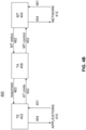
FIG. 4B illustrates a flow diagram of a process for anMT 404 and aTE 402 of aUE 400 device to exchange information in accordance with some embodiments. Process and logical flow diagrams as illustrated herein provide examples of sequences of various process actions. Although the actions are shown in a particular sequence or order, unless otherwise specified, the order of the actions may be modified. Thus, the described and illustrated implementations should be understood only as examples, and the illustrated processes may be performed in a different order, and some actions may be performed in parallel. Additionally, one or more actions may be omitted in various embodiments; thus, not all actions are executed in every implementation. Other process flows are possible. - The one or
more applications 410 may be executed via theUE 400 for utilizing PDNs. The one ormore applications 410 may indicate a command for theTE 402 to control the MT 404 (shown as operation 451). TheTE 402 sends attention (AT) commands to the TA 406 (shown as operation 452), which are then parsed as MT control commands (shown as operation 453). - The AT commands can include, for example, general commands, call control commands, network service related commands, MT control and status commands, MT errors result codes, commands for packet domain, commands for voice group call service (VGCS) and voice broadcast service (VBS), and commands for the Universal Subscriber Identity Module (USIM) Application Toolkit.
- The
MT 404 may transmit and receive signal data to and from the one or more networks 412 (shown asoperations UE 400 moves. TheMT 404 can send MT status messages to the TA 406 (shown as operation 462), which theTA 406 sends to theTE 402 as responses to the AT commands (shown as operation 463). Data from these responses may then be transmitted to the one or more applications 410 (shown as operation 464). - Thus, AT commands provide a way for the
TE 402 to control theMT 404. TheUE 400 may be coupled to a cellular network and/or a non-cellular network (e.g., a WLAN). When theUE 400 is initially coupled to a cellular network and then subsequently also connects to a non-cellular network, theUE 400 may perform traffic offloading - i.e., offloading a PDN connection to the non-cellular network. Cellular network components (e.g., thePGW 226 ofFIG. 2 ) may decide which PDN connection is to be offloaded to the non-cellular network, and provide this information to theMT 404 via one or more NAS messages. - In some embodiments, existing AT commands sent by the
TE 402 and their associated responses sent by theMT 404 are modified so that they may indicate to theTE 402 which PDN connections can be offloaded to the non-cellular network. -
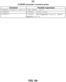
FIG. 5A - FIG. 5C illustrate command/response tables for modified AT commands in accordance with some embodiments. As described below, these modified AT commands allow for aTE 402 to receive data indicating offload-ability characteristics for specific PDN connections, and also allow for a TE to independently query and determine WLAN offload characteristics of individual primary and secondary packet data protocol (PDP) contexts of a PDN connection. The command/response tables described below may be used in a variety of cellular communications protocols, such as 3GPP (LTE) protocols, legacy 3GPP UMTS Terrestrial Radio Access Network (UTRAN) network protocols, and so forth. - For the purposes of the illustrated command/response tables, the following syntactical definitions apply:
- <CR> Carriage return character, which value is specified with command S3.
- <LF> Linefeed character, which value is specified with command S 4.
- <...> Name enclosed in angle brackets is a syntactical element. Brackets themselves do not appear in the command line.
- [...] Optional subparameter of a command or an optional part of TA information response is enclosed in square brackets. Brackets themselves do not appear in the command line. When subparameter is not given in parameter type commands, new value equals to its previous value. In action type commands, action should be done on the basis of the recommended default setting of the subparameter.
- underline Underlined defined subparameter value is the recommended default setting of this subparameter. In parameter type commands, this value should be used in factory settings which may be configured, for example, by ITU-T Recommendation V.250: "Serial asynchronous automatic dialing and control." In action type commands, this value should be used when subparameter is not given.
-
FIG. 5A illustrates a command/response table 500 for the packet domain event reporting (+CGEREP) AT command. In this embodiment, the +CGREP command is updated to provide WLAN offload characteristics of a PDN connection, when the PDN connection is activated, deactivated or modified. - More specifically, with regard to the +CGREP command, set command enables or disables sending of unsolicited result codes, +CGEV : XXX from MT to TE in the case of certain events occurring in the Packet Domain MT or the network. <mode> controls the processing of unsolicited result codes specified within this command. <bfr> controls the effect on buffered codes when <mode> 1 or 2 is entered. If a setting is not supported by the MT, ERROR or +CME ERROR: is returned. Refer subclause 9.2 for possible <err> values may comprise, for example, values defined in subclause 9.2 of 3GPP TS 27.007 "AT Command set for User Equipment (UE)."
- Read command returns the current mode and buffer settings
Test command returns the modes and buffer settings supported by the MT as compound values. - Defined values are as follows:
- <mode>: integer type
- 0 buffer unsolicited result codes in the MT; if MT result code buffer is full, the oldest ones can be discarded. No codes are forwarded to the TE.
- 1 discard unsolicited result codes when MT-TE link is reserved (e.g. in on-line data mode); otherwise forward them directly to the TE
- 2 buffer unsolicited result codes in the MT when MT-TE link is reserved (e.g. in on-line data mode) and flush them to the TE when MT-TE link becomes available; otherwise forward them directly to the TE
- <bfr>: integer type
- 0 MT buffer of unsolicited result codes defined within this command is cleared when <mode> 1 or 2 is entered
- 1 MT buffer of unsolicited result codes defined within this command is flushed to the TE when <mode> 1 or 2 is entered (OK response shall be given before flushing the codes)
- Defined events are valid for GPRS/UMTS and LTE.
- For network attachment, the following unsolicited result codes and the corresponding events are defined:
- +CGEV: NW DETACH
The network has forced a PS detach. This implies that all active contexts have been deactivated. These are not reported separately. - +CGEV: ME DETACH
The mobile termination has forced a PS detach. This implies that all active contexts have been deactivated. These are not reported separately. - For MT class, the following unsolicited result codes and the corresponding events are defined:
- +CGEV: NW CLASS <class>
The network has forced a change of MT class. The highest available class is reported (see +CGCLASS). The format of the parameter <class> is found in command +CGCLASS. - +CGEV: ME CLASS <class>
The mobile termination has forced a change of MT class. The highest available class is reported (see +CGCLASS). The format of the parameter <class> is found in command +CGCLASS. - For PDP context activation, the following unsolicited result codes and the corresponding events are defined:
- +CGEV: NW PDN ACT <cid> [,<WLAN_Offload>]
- The network has activated a context. The context represents a Primary PDP context in GSM/UMTS. The <cid> for this context is provided to the TE. The format of the parameter <cid> is found in command +CGDCONT.
- <WLAN_Offload>: integer type. An integer that indicates whether traffic can be offloaded using the specified PDN connection via a WLAN or not. This refers to bit 1 (E-UTRAN offload acceptability value) and bit 2 (UTRAN offload acceptability value) in the WLAN offload acceptability IE as specified in, for example, 3GPP TS 24.008: "Mobile Radio Interface Layer 3 specification; Core Network Protocols-Stage 3."
- 0 offloading the traffic of the PDN connection via a WLAN when in S1 mode or when in Iu mode is not acceptable.
- 1 offloading the traffic of the PDN connection via a WLAN when in S1 mode is acceptable, but not acceptable in Iu mode.
- 2 offloading the traffic of the PDN connection via a WLAN when in Iu mode is acceptable, but not acceptable in S1 mode.
- 3 offloading the traffic of the PDN connection via a WLAN when in S1 mode or when in Iu mode is acceptable.
- +CGEV: ME PDN ACT <cid>[,<reason>[,<cid_other>]][,<WLA N_Offload>]
- The mobile termination has activated a context. The context represents a PDN connection in LTE or a Primary PDP context in GSM/UMTS. The <cid> for this context is provided to the TE. This event is sent either in result of explicit context activation request (+CGACT), or in result of implicit context activation request associated to attach request (+CGATT=1). The format of the parameters <cid> and <cid_other> are found in command +CGDCONT. The format of the parameter <WLAN_Offload> is defined above.<reason>: integer type; indicates the reason why the context activation request for PDP type IPv4v6 was not granted. This parameter is only included if the requested PDP type associated with <cid> is IPv4v6, and the PDP type assigned by the network for <cid> is either IPv4 or IPv6.
- 0 IPv4 only allowed
- 1 IPv6 only allowed
- 2 single address bearers only allowed.
- 3 single address bearers only allowed and MT initiated context activation for a second address type bearer was not successful.
- <cid_other>: integer type; indicates the context identifier allocated by MT for an MT initiated context of a second address type. MT shall only include this parameter if <reason> parameter indicates single address bearers only allowed, and MT supports MT initiated context activation of a second address type without additional commands from TE, and MT has activated the PDN connection or PDP context associated with <cid_other>.
- <cid_other> returned to TE.
- +CGEV: NW ACT <p_cid>, <cid>, <event_type> [,<WLAN_Offload>]
- The network has activated a context. The <cid> for this context is provided to the TE in addition to the associated primary <p_cid>. The format of the parameters <p_cid> and <cid> are found in command +CGDSCONT. The format of the parameter <WLAN_Offload> is defined above.
- <event_type>: integer type; indicates whether this is an informational event or whether the TE has to acknowledge it.
- 0 Informational event
- 1 Information request: Acknowledgement required. The acknowledgement can be accept or reject, see +CGANS.
- +CGEV: ME ACT <p_cid>, <cid>, <event_type> [,<WLAN_Offload>]
The network has responded to an ME initiated context activation. The <cid> for this context is provided to the TE in addition to the associated primary <pcid>. The format of the parameters <p_cid> and <cid> are found in command +CGDSCONT. The format of the parameters <event_type> and <WLAN_Offload> is defined above. - For PDP context deactivation, the following unsolicited result codes and the corresponding events are defined:
- +CGEV: NW DEACT <PDP_type>, <PDP_addr>, [<cid>]
The network has forced a context deactivation. The <cid> that was used to activate the context is provided if known to the MT. The format of the parameters <PDP_type>, <PDP_addr> and <cid> are found in command +CGDCONT. - +CGEV: ME DEACT <PDP_type>, <PDP_addr>, [<cid>]
The mobile termination has forced a context deactivation. The <cid> that was used to activate the context is provided if known to the MT. The format of the parameters <PDP_type>, <PDP_addr> and <cid> are found in command +CGDCONT. - +CGEV: NW PDN DEACT <cid>[,<WLAN_Offload>]
The network has deactivated a context. The context represents a PDN connection in LTE or a Primary PDP context in GSM/UMTS. The associated <cid> for this context is provided to the TE. The format of the parameter <cid> is found in command +CGDCONT. The format of the parameter <WLAN_Offload> is defined above.
NOTE: Occurrence of this event replaces usage of the event - +CGEV: NW DEACT <PDP_type>, <PDP_addr>, [<cid>].
- +CGEV: ME PDN DEACT <cid>
The mobile termination has deactivated a context. The context represents a PDN connection in LTE or a Primary PDP context in GSM/UMTS. The <cid> for this context is provided to the TE. The format of the parameter <cid> is found in command +CGDCONT.
NOTE: Occurrence of this event replaces usage of the event - +CGEV: ME DEACT <PDP_type>, <PDP_addr>, [<cid>].
- +CGEV: NW DEACT <p_cid>, <cid>, <event_type> [,<WLAN_Offload>]
The network has deactivated a context. The <cid> for this context is provided to the TE in addition to the associated primary <pcid>. The format of the parameters <p_cid> and <cid> are found in command +CGDSCONT. The format of the parameters <event_type> <WLAN_Offload> is defined above.
NOTE: Occurrence of this event replaces usage of the event - +CGEV: NW DEACT <PDP_type>, <PDP_addr>, [<cid>].
- +CGEV: ME DEACT <p_cid>, <cid>, <event_type>
The network has responded to an ME initiated context deactivation request. The associated <cid> is provided to the TE in addition to the associated primary <p_cid>. The format of the parameters <p_cid> and <cid> are found in command +CGDSCONT. The format of the parameter <event_type> is defined above.
NOTE: Occurrence of this event replaces usage of the event - +CGEV: ME DEACT <PDP_type>, <PDP_addr>, [<cid>].
- For PDP context modification, the following unsolicited result codes and the corresponding events are defined:
- +CGEV: NW MODIFY <cid>, <change_reason>, <event_type> [,<WLAN_Offload>]
The network has modified a context. The associated <cid> is provided to the TE in addition to the <change_reason> and <event_type>. The format of the parameter <cid> is found in command +CGDCONT or +CGDSCONT. The format of the parameters <change_reason>, <event_type>, and <WLAN_Offload> are defined above. - <change_reason>: integer type; a bitmap that indicates what kind of change occurred.
- The <changereason> value is determined by summing all the applicablebits. For example if both the values of the QoS changed (Bit 2) and WLAN_Offload changed (Bit 3) havechanged, then <change_reason> value is 6.
- NOTE: The WLAN offload value will change when
bit 1 or bit 2 or both of the indicators in the WLAN offload acceptability IE change, see the parameter <WLAN_Offload> defined above. -
Bit 1 TFT changed - Bit 2 Qos changed
- Bit 3 WLAN Offload changed
- +CGEV: ME MODIFY <cid>, <change_reason>, <event_type> [,<WLAN_Offload>]
The mobile termination has modified a context. The associated <cid> is provided to the TE in addition to the <changereason> and <event__type>. The format of the parameter <cid> is found in command +CGDCONT or +CGDSCONT. The format of the parameters <change_reason>, <event_type> and <WLAN_Offload> are defined above. - For other PDP context handling, the following unsolicited result codes and the corresponding events are defined:
- +CGEV: REJECT <PDP_type>, <PDP_addr>
A network request for context activation occurred when the MT was unable to report it to the TE with a +CRING unsolicited result code and was automatically rejected. The format of the parameters <PDP_type> and <PDP_addr> are found in command +CGDCONT.
NOTE: This event is not applicable for EPS. - +CGEV: NW REACT <PDP_type>, <PDP_addr>, [<cid>]
The network has requested a context reactivation. The <cid> that was used to reactivate the context is provided if known to the MT. The format of the parameters <PDP_type>, <PDP_addr> and <cid> are found in command +CGDCONT.
NOTE: This event is not applicable for EPS -
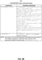
FIG. 5B illustrates a command/response table 510 for the PDP context read dynamic parameters (+CGCONTRDP) command. In this embodiment, the +CGCONTRDP command can be used to query WLAN offload characteristics of any active PDN connection associated with a primary PDP context. As discussed herein a PDP Context comprises a record of parameters, including information for establishing an end-to-end connection, such as PDP Type, PDP address type, QoS profile request (e.g., QoS parameters requested by user), QoS profile negotiated (e.g., QoS parameters negotiated by network), Authentication type (e.g., PAP or CHAP), and DNS type (e.g., Dynamic DNS or Static DNS). - More specifically, with regard to the + CGCONTRDP command, the execution command returns the relevant information <bearer_id>, <apn>, <local_addr and subnet_mask>, <gw_addr>, <DNS_prim_addr>, <DNS_sec_addr>, <P-CSCF_prim_addr>, <P-CSCF_sec_addr>,<IM_CN+Signalling_Flag>, <LIPA_indication>, <IPv4_MTU> and <WLAN _Offload> for an active non secondary PDP context with the context identifier <cid>.
- The above fields may describe, for example, a bearer identification associated with the Primary PDP context, an access point name associated with the Primary PDP context, a local address and subnet mask associated with the Primary PDP context, a gateway address associated with the Primary PDP Context, primary or secondary domain name system (DNS) Server address associated with the primary context, primary or secondary proxy-call session control function (P-CSCF) Server address associated with the Primary PDP context, an IP Multimedia Core Network (IM_CN) flag associated with the Primary PDP context identifying the PDN connection as a multimedia PDN Connection, a local IP access (LIPA) indicator associated with the Primary PDP context, an IP maximum transmission unit (MTU) defining a maximum packet size for the primary PDP Context, or data indicating whether the PDN connection associated with a Primary PDP context can be offloaded from the cellular network to the non-cellular network.
- If the MT indicates more than two IP addresses of P-CSCF servers or more than two IP addresses of DNS servers, multiple lines of information per <cid> will be returned.
- If the MT has dual stack capabilities, at least one pair of lines with information is returned per <cid>. First one line with the IPv4 parameters followed by one line with the IPv6 parameters. If this MT with dual stack capabilities indicates more than two IP addresses of P-CSCF servers or more than two IP addresses of DNS servers, multiple of such pairs of lines are returned.
- NOTE: If the MT doesn't have all the IP addresses to be included in a line, e.g. in case the UE received four IP addresses of DNS servers and two IP addresses of P-CSCF servers, the parameter value representing an IP address that cannot be populated is set to an empty string or an absent string.
- If the parameter <cid> is omitted, the relevant information for all active non secondary PDP contexts is returned.
- The test command returns a list of <cid>s associated with active non secondary contexts.
- Defined values:
- <cid>: integer type; specifies a particular non secondary PDP context definition. The parameter is local to the TE-MT interface and is used in other PDP context-related commands (see the +CGDCONT and +CGDSCONT commands).
- <bearer id>: integer type; identifies the bearer, i.e. the EPS bearer in EPS and the NSAPI in UMTS/GPRS.
- <apn>: string type; a logical name that was used to select the GGSN or the external packet data network.
- <local_addr and subnet_mask>: string type; shows the IP address and subnet mask of the MT. The string is given as dot-separated numeric (0-255) parameters on the form:
- "a1.a2.a3.a4.m1.m2.m3.m4" for IPv4 or "a1.a2.a3.a4.a5.a6.a7.a8.a9.a10.a11.a12.a13.a14.a15.a16.m1.m2.m3.m4.m 5.m6.m7.m8.m9.m10.m11.m12.m13.m14.m15.m16" for IPv6.
- When +CGPIAF is supported, its settings can influence the format of this parameter returned with the execute form of +CGCONTRDP.
- <gw_addr>: string type; shows the Gateway Address of the MT. The string is given as dot-separated numeric (0-255) parameters.
When +CGPIAF is supported, its settings can influence the format of this parameter returned with the execute form of +CGCONTRDP. - <DNS_prim_addr>: string type; shows the IP address of the primary DNS server.
When +CGPIAF is supported, its settings can influence the format of this parameter returned with the execute form of +CGCONTRDP. - <DNS_sec_addr>: string type; shows the IP address of the secondary DNS server.
When +CGPIAF is supported, its settings can influence the format of this parameter returned with the execute form of +CGCONTRDP. - <P_CSCF_prim_addr>: string type; shows the IP address of the primary P-CSCF server.
When +CGPIAF is supported, its settings can influence the format of this parameter returned with the execute form of +CGCONTRDP. - <P_CSCF_sec_addr>: string type; shows the IP address of the secondary P-CSCF server.
When +CGPIAF is supported, its settings can influence the format of this parameter returned with the execute form of +CGCONTRDP. - <IM_CN_Signalling_Flag>: integer type; shows whether the PDP context is for IM CN subsystem-related signalling only or not.
- 0 PDP context is not for IM CN subsystem-related signalling only
- 1 PDP context is for IM CN subsystem-related signalling only
- <LIPA_indication>: integer type; indicates that the PDP context provides connectivity using a LIPA PDN connection. This parameter cannot be set by the TE.
- 0 indication not received that the PDP context provides connectivity using a LIPA PDN connection
- 1 indication received that the PDP context provides connectivity using a LIPA PDN connection
- <IPv4_MTU>: integer type; shows the IPv4 MTU size in octets.
- <WLAN _Offload>: integer type. An integer that indicates whether traffic can be offloaded using the specified PDN connection via a WLAN or not. This refers to
bits 1 and 2 of the WLAN offload acceptability IE as specified in, for example, 3GPP TS 24.008 subclause 10.5.6.20.- 0 offloading the traffic of the PDN connection via a WLAN when in S1 mode or when in Iu mode is not acceptable.
- 1 offloading the traffic of the PDN connection via a WLAN when in S1 mode is acceptable, but not acceptable in Iu mode.
- 2 offloading the traffic of the PDN connection via a WLAN when in Iu mode is acceptable, but not acceptable in S1 mode.
- 3 offloading the traffic of the PDN connection via a WLAN when in S1 mode or when in Iu mode is acceptable.
-
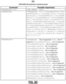
FIG. 5C illustrates a command/response table 520 for the secondary PDP context read dynamic parameters (+CGSCONTRDP) command. In this embodiment, the +CGSCONTRDP command can be used to query WLAN offload characteristics of an active PDN connection associated with any active secondary PDP context. - More specifically, with regard to the + CGSCONTRDP command, the execution command returns <p_cid>, <bearer_id>, <IM_CN_Signalling_Flag> and <WLAN _Offload> for an active secondary PDP context with the context identifier <cid>.
- If the parameter <cid> is omitted, the <cid>, <p_cid>, <bearer_id>, <IM_CN_Signalling_Flag> and <WLAN_Offload> are returned for all active secondary PDP contexts.
- In EPS, the Traffic Flow parameters are returned.
- NOTE: Parameters for UE initiated and network initiated PDP contexts are returned.
- The test command returns a list of <cid>s associated with active secondary PDP contexts.
- Defined values:
- <cid>: integer type; specifies a particular active secondary PDP context or Traffic Flows definition. The parameter is local to the TE-MT interface and is used in other PDP context-related commands (see the +CGDCONT and +CGDSCONT commands).
- <p_cid>: integer type; specifies a particular PDP context definition or default EPS context Identifier which has been specified by use of the +CGDCONT command. The parameter is local to the TE-MT interface (see the +CGDSCONT command).
- <bearer id>: integer type; identifies the bearer, EPS Bearer in EPS and NSAPI in UMTS/GPRS.
- <IM_CN_Signalling_Flag>: integer type; shows whether the PDP context is for IM CN subsystem-related signalling only or not.
- 0 PDP context is not for IM CN subsystem-related signalling only
- 1 PDP context is for IM CN subsystem-related signalling only
- <WLAN _Offload>: integer type. An integer that indicates whether traffic can be offloaded using the specified PDN connection via a WLAN or not. This refers to
bits 1 and 2 of the WLAN offload acceptability IE as specified in, for example, 3GPP TS 24.008 , subclause 10.5.6.20.- 0 offloading the traffic of the PDN connection via a WLAN when in S1 mode or when in Iu mode is not acceptable.
- 1 offloading the traffic of the PDN connection via a WLAN when in S1 mode is acceptable, but not acceptable in Iu mode.
- 2 offloading the traffic of the PDN connection via a WLAN when in Iu mode is acceptable, but not acceptable in S1 mode.
- 3 offloading the traffic of the PDN connection via a WLAN when in S1 mode or when in Iu mode is acceptable.
- Thus, in the embodiments discussed above, pre-existing AT Commands +CGEREP, +CGCONTRDP and +CGSCONTRDP are extended to provide WLAN offloading indications on a per PDN connection basis to a TE. Furthermore, the WLAN_Offload setting could be considered as being specific for each individual PDN connection. Adding WLAN_Offload setting as a new parameter allows having this setting apply to offloading of every single PDN connection. Furthermore this parameter allows to determine WLAN offload characteristics to specific Radio Access Technologies (RATs) such as UTRAN or EUTRAN.
-
FIG. 5D illustrates a command/response table 530 for providing WLAN offload assistance information in accordance with some embodiments. The table 540 illustrates a WLAN Offload Assistance Data (+CWLANOLAD) AT command; set command enables or disables the sending of the following unsolicited result code from MT to TE whenever the WLAN offload assistance data changes at the MT.
+CWLANOLADI: [,<threshRSCPLow>,<threshRSCPHigh>[,<thres hEcnoLow>,<threshEcnoHigh> [,<threshRSRPLow>,<threshRSR PHigh> [,<threshRSRQLow>,<threshRSRQHigh> [, <threshChUti lLow>,<threshChUtilHigh>[,<threshBackhRateDLLow>,<thre shBackhRateDLHigh>[,<threshBackhRateULLow>,<threshBack hRateULHigh>[,<threshBeaconRSSILow>,<threshBeaconRSSIH igh>[,<opi>[,<tSteering>[,<WLANIdentifierListLength>[, <ssid_1>,<bssid_1>,<hessid_1>][,...][,<ssid_m>,<bssid_m> ,<hessid_m>]]]]]]]]]]]] - If a setting is not supported by the MT, ERROR or +CME ERROR: is returned.
- Read command returns the current status of result code and the WLAN offload assistance data currently available at the MT.
- Test command returns the values supported by MT as compound values.
- Defined values:
- <n>: integer type
- 0 disable WLAN Offload Assistance Data unsolicited result code
- 1 enable WLAN Offload Assistance Data unsolicited result code +CWLANOLADI
- <threshRSCPLow>: integer type; indicates the threshold for received signal code power for offloading traffic from UTRAN to WLAN.
- <threshRSCPHigh>: integer type; indicates the threshold for received signal code power for offloading traffic from WLAN to UTRAN.
- <threshEcnoLow>: integer type; indicates the threshold for ratio of the received energy per pseudorandom noise (PN) chip to the total received power spectral density for offloading traffic from UTRAN to WLAN.
- <threshEcnoHigh>: integer type; indicates the threshold for ratio of the received energy per PN chip to the total received power spectral density for offloading traffic from WLAN to UTRAN.
- <threshRSRPLow>: integer type; indicates the threshold for reference signal received power for offloading traffic from E-UTRAN to WLAN.
- <threshRSRPHigh>: integer type; indicates the threshold for reference signal received power for offloading traffic from WLAN to E-UTRAN.
- <threshRSRQLow>: integer type; indicates the threshold for reference signal received quality for offloading traffic from E-UTRAN to WLAN.
- <threshRSRQHigh>: integer type; indicates the threshold for reference signal received quality for offloading traffic from WLAN to E-UTRAN.
- (the above values may be consistent with, for example, subclause 8.69 of 3GPP TS 27.007 "AT Command set for User Equipment (UE)."
- <threshChUtilLow>: integer type; indicates the low threshold value of WLAN channel utilization (BSS load).obtained from 802.11 (Beacon or Probe Response) signalling for traffic offloading to WLAN.
- <threshChUtilHigh>: integer type; indicates the high threshold value of WLAN channel utilization (BSS load) obtained from 802.11 (Beacon or Probe Response) signalling for traffic offloading to UTRAN or E-UTRAN. Refer to IEEE 802.11 [152].
- (the above values may be consistent with an IEEE 802.11 (for example IEEE 802.11n) radio communication standard.
- <threshBackhRateDLLow>: integer type; indicates the low threshold value of backhaul available downlink bandwidth for traffic offloading to UTRAN or E-UTRAN..
- <threshBackhRateDLHigh>: integer type; indicates the high threshold value of backhaul available downlink bandwidth for traffic offloading to WLAN.
- <threshBackhRateULLow>: integer type; indicates the low threshold value of backhaul available uplink bandwidth for traffic offloading to UTRAN or E-UTRAN.
- <threshBackhRateDLHigh>: integer type; indicates the high threshold value of backhaul available uplink bandwidth for traffic offloading to WLAN.
- (the above values may be consistent with a Wi-Fi Certified passpoint (e.g., Hot Spot 2.0) specification.
- <threshBeaconRSSILow>: integer type; indicates the low threshold value of beacon RSSI used for traffic offloading to UTRAN or E-UTRAN.
- <threshBeaconRSSIHigh>: integer type; indicates the high threshold value of beacon RSSI used for traffic offloading to WLAN.
- (the above values may be consistent with an IEEE 802.11 (for example IEEE 802.11n) radio communication standard.
- <opi>: integer type;A 16-bit integer formatted as a bitmap that specifies the Offload Preference Indicator.
- (the above values may be consistent with, for example, 3GPP TS 24.312 "Access Network Discovery and Selection Function (ANDSF) Management Object (MO)."
- <tSteering>: integer type; indicates the timer value in seconds during which the rules should be fulfilled before starting traffic offloading between E-UTRAN and WLAN.
- <ssid>: octet string type; indicates the 802.11 Service Set Identifier (SSID).
- <bssid>: octet string type; indicates the 802.11 Basic Service Set Identifier (BSSID).
- <hessid>: octet string type; indicates the 802.11 Homogenous Extended Service Set Identifier (HESSID).
- (the above values may be consistent with an IEEE 802.11 (for example IEEE 802.11n) radio communication standard.
- <WLANIdentifierListLength>: integer type; indicates the number of entries in WLAN identifier list which is a tuple consisting of <ssid>, <bssid>, <hessid> identifiers. If any of the identifier is not present it will be indicated as an empty string.
-
FIG. 5E illustrates a command/response table 540 for providing WLAN Offload Cell Measurement information in accordance with some embodiments. The table 550 illustrates a WLAN Offload Cell Measurement (+CWLANOLCM) AT command; set command enables or disables the sending of the following unsolicited result code from MT to TE whenever the cell measurement parameters meet the criteria for WLAN offloading based on configured thresholds.
+CWLANOLCMI: <rscp>,<ecno>,<rsrp>,<rsrq> - If a setting is not supported by the MT, ERROR or +CME ERROR: is returned.
- Read command returns the current status of result code presentation and the measurements from the current primary serving cell at the MT.
- Test command returns the values supported by MT as compound values.
- Defined values:
- <n>: integer type
- 0 disable WLAN Offload Cell Measurement unsolicited result code
- 1 enable WLAN Offload Cell Measurement unsolicited result code +CWLANOLCMI
- <rscp>: integer type; indicates the received signal code power.
- <ecno>: integer type; indicates the ratio of the received energy per PN chip to the total received power spectral density.
- <rsrp>: integer type; indicates the reference signal received power.
- <rsrq>: integer type; indicates the reference signal received quality.
- (the above values may be consistent with, for example, the +CESQ command as described in subclause 8.69 of 3GPP TS 27.007 "AT Command set for User Equipment (UE)."
-
FIG. 6 illustrates a block diagram of aUE 600 and aneNodeB 650, in accordance with some embodiments. It should be noted that, in some embodiments, theeNodeB 650 can be a stationary (non-mobile) device. TheUE 600 can include physical layer circuitry (PHY) 602 for transmitting and receiving signals to and from theeNodeB 650, other eNodeBs, other UEs, or other devices using one ormore antennas 601, while theeNodeB 650 can include physical layer circuitry (PHY) 652 for transmitting and receiving signals to and from theUE 600, other eNodeBs, other UEs, or other devices using one ormore antennas 651. TheUE 600 can also include medium access control layer (MAC)circuitry 604 for controlling access to the wireless medium, while theeNodeB 650 can also includeMAC circuitry 654 for controlling access to the wireless medium. TheUE 600 can also includeprocessing circuitry 606 andmemory 608 arranged to perform the operations described herein, and theeNodeB 650 can also includeprocessing circuitry 656 andmemory 658 arranged to perform the operations described herein. - The
antennas antennas - Although the
UE 600 andeNodeB 650 are each illustrated as having several separate functional elements, one or more of the functional elements can be combined and can be implemented by combinations of software-configured elements, such as processing elements including digital signal processors (DSPs), and/or other hardware elements. For example, some elements can comprise one or more microprocessors, DSPs, field-programmable gate arrays (FPGAs), application specific integrated circuits (ASICs), radiofrequency integrated circuits (RFICs), and combinations of various hardware and circuitry for performing at least the functions described herein. In some embodiments, the functional elements can refer to one or more processes operating on one or more processing elements. - Embodiments can be implemented in one or a combination of hardware, firmware, and software. Embodiments can also be implemented as instructions stored on a computer-readable storage device, which can be read and executed by at least one processor to perform the operations described herein. A computer-readable storage device can include any non-transitory mechanism for storing information in a form readable by a machine (e.g., a computer). For example, a computer-readable storage device can include read-only memory (ROM), random-access memory (RAM), magnetic disk storage media, optical storage media, flash memory devices, and other storage devices and media. Some embodiments can include one or more processors and can be configured with instructions stored on a computer-readable storage device.
- In accordance with embodiments, the
UE 600 can operate in accordance with a D2D communication mode. TheUE 600 can includeprocessing circuitry 606 configured to determine a synchronization reference time based on reception of one or more signals from theeNodeB 650. Thehardware processing circuitry 606 can be further configured to, during a D2D communication session, transmit multi-time transmission interval bundle groups (MTBGs) of data symbols during a first group of data transmission intervals (DTIs) and refrain from transmission of data symbols during a second group of DTIs that is exclusive of the first group of DTIs. Starting times of the DTIs can be based, at least partly, on the synchronization reference time. Thehardware processing circuitry 606 can be further configured to transmit, during an in-network communication session exclusive of the D2D communication session, data symbols according to a time transmission interval (TTI) reference time that is synchronized to the synchronization reference time. - In some scenarios, the
UE 600, operating in a cellular communication network, can begin to experience performance degradation for various reasons. As an example, user loading or throughput demands of thenetwork 412 can become high. As another example, theUE 600 can move toward or beyond the edges of coverage cells. While operating in thenetwork 412, theUE 600 can actually be in communication with other UEs that are physically located in close proximity to theUE 600, although the communication can take place through thenetwork 412. -
FIG. 7 illustrates a block diagram illustrating components of a machine, according to some example embodiments, able to read instructions from a machine-readable medium and perform any one or more of the methodologies discussed herein, according to aspects of the disclosure. In particular,FIG. 7 illustrates an exemplary computer system 700 (which can comprise any of the network elements discussed above) within whichsoftware 724 for causing the machine to perform any one or more of the methodologies discussed herein can be executed. In alternative embodiments, the machine operates as a standalone device or can be connected (e.g., networked) to other machines. In a networked deployment, the machine can operate in the capacity of a server or a client machine in a server-client network environment, or as a peer machine in a peer-to-peer (or distributed) network environment. Thecomputer system 700 can function as any of the above described UEs or eNodeBs, and can be a personal computer (PC), a wearable mobile computing device, a tablet PC, a set-top box (STB), a PDA, a cellular telephone, a web appliance, a network router, switch, or bridge, or any machine capable of executing instructions (sequential or otherwise) that specify actions to be taken by that machine. Further, while only a single machine is illustrated, the term "machine" can also be taken to include any collection of machines that individually or jointly execute a set (or multiple sets) of instructions to perform any one or more of the methodologies discussed herein. - The
example computer system 700 includes a processor 702 (e.g., a central processing unit (CPU), a graphics processing unit (GPU), or both), amain memory 704, and astatic memory 706, which communicate with each other via abus 708. Thecomputer system 700 can further include a video display unit 710 (e.g., an LCD or a cathode ray tube (CRT)). Thecomputer system 700 also includes an alphanumeric input device 712 (e.g., a keyboard), a user interface navigation (or cursor control) device 714 (e.g., a mouse), astorage device 716, a signal generation device 718 (e.g., a speaker), and anetwork interface device 720. - The
storage device 716 includes a non-transitory machine-readable medium 722 on which is stored one or more sets of data structures andsoftware 724 embodying or utilized by any one or more of the methodologies or functions described herein. Thesoftware 724 can also reside, completely or at least partially, within themain memory 704 and/or within theprocessor 702 during execution thereof by thecomputer system 700, with themain memory 704 and theprocessor 702 also constituting non-transitory machine-readable media 722. Thesoftware 724 can also reside, completely or at least partially, within thestatic memory 706. - While the non-transitory machine-
readable medium 722 is shown, in an example embodiment, to be a single medium, the term "machine-readable medium" can include a single medium or multiple media (e.g., a centralized or distributed database, and/or associated caches and servers) that store the one or more data structures andsoftware 724. The term "machine-readable medium" can also be taken to include any tangible medium that is capable of storing, encoding, or carrying instructions for execution by the machine and that cause the machine to perform any one or more of the methodologies of the present embodiments, or that is capable of storing, encoding, or carrying data structures utilized by or associated with such instructions. The term "machine-readable medium" can accordingly be taken to include, but not be limited to, solid-state memories, and optical and magnetic media. Specific examples of machine-readable media 722 include non-volatile memory, including by way of example semiconductor memory devices (e.g., erasable programmable read-only memory (EPROM), electrically erasable programmable read-only memory (EEPROM), and flash memory devices); magnetic disks such as internal hard disks and removable disks; magneto-optical disks; and compact disc read-only memory (CD-ROM) and digital versatile disc (or digital video disc) read-only memory (DVD-ROM) disks. - The
software 724 can further be transmitted or received over acommunications network 726 using a transmission medium. Thesoftware 724 can be transmitted using thenetwork interface device 720 and any one of a number of well-known transfer protocols (e.g., HyperText Transfer Protocol (HTTP)). Examples ofcommunication networks 726 include a local area network (LAN), a wide area network (WAN), theInternet 112, mobile telephone networks, plain old telephone service (POTS) networks, and wireless data networks (e.g., WiFi and WiMax networks). The term "transmission medium" can be taken to include any intangible medium capable of storing, encoding, or carrying instructions for execution by the machine, and includes digital or analog communications signals or other intangible media to facilitate communication ofsuch software 724. - The drawings and the forgoing description give examples of the present disclosure. Although embodiments are depicted as a number of disparate functional items, those skilled in the art will appreciate that one or more of such elements can well be combined into single functional elements. Alternatively, certain elements can be split into multiple functional elements. Elements from one embodiment can be added to another embodiment. For example, orders of processes described herein can be changed and are not limited to the manner described herein. Moreover, the operations of any flow diagram need not be implemented in the order shown; nor do all of the operations necessarily need to be performed. Also, those operations that are not dependent on other operations can be performed in parallel with the other operations.
Claims (12)
- A user equipment, UE (102, 300, 400), comprising:a mobile termination, MT (404), configured to transmit and receive messages from a cellular network; anda terminal equipment, TE (402), configured to execute one or more applications to utilize one or more packet data network, PDN, connections of the cellular network or a wireless local area network, WLAN; andcharacterized in that
the UE is configured to:
cause a terminal adaptor, TA (406), of the UE (102, 300, 400) to:forward an attention, AT, command received from the TE (402) as an MT control command to the MT (404);forward an MT (404) status message generated by the MT (404) as an AT command response to the TE (402); andforward an unsolicited result code +CGEV generated by the MT (404) to the TE (402), indicating whether a specific PDN connection can be offloaded from the cellular network to the WLAN, when acceptability of offloading the specific PDN connection changes. - The UE (102, 300, 400) of claim 1, wherein the AT command comprises a packet domain event reporting +CGEREP AT command.
- The UE (102, 300, 400) of claim 2, wherein the AT command indicates that the MT activated a context, and the context represents a primary packet data protocol (PDP) context or the specific PDN connection.
- The UE (102, 300, 400) of claim 3, wherein the AT command is sent in response to an explicit context activation request +CGACT or an implicit context activation request associated to attach request +CGATT=1.
- The UE (102, 300, 400) of claim 4, wherein the AT command comprises a reason parameter, and the reason parameter is an integer that indicates a reason why context activation was not granted.
- The UE (102, 300, 400) of claim 5, wherein the reason parameter is included if a requested PDP type is IPv4v6, and a PDP type assigned by the network is either IPv4 or IPv6.
- The UE (102, 300, 400) of claim 1, wherein the cellular network is:a Universal Mobile Telecommunications Service Terrestrial Radio Access Network/ Global System for Mobile Communications, GSM, Edge Radio Access Network, UTRAN/GERAN,-based serving network; oran Evolved Universal Mobile Telecommunications Service Terrestrial Radio Access Network, E-UTRAN,-based serving network.
- The UE (102, 300, 400) of claim 1, wherein the MT is further configured to forward an AT command, wherein the AT command further comprises a set command to enable and disable sending of unsolicited result codes.
- A non-transitory computer-readable storage medium comprising contents that, when executed by a user equipment, UE (102, 300, 400), cause the UE (102, 300, 400) to perform operations to:cause a mobile termination, MT (404), of the UE (102, 300, 400) to transmit and receive messages from a cellular network; andcause a terminal equipment, TE (402), of the UE (102, 300, 400) to execute one or more applications to utilize one or more packet data network, PDN, connections of the cellular network or a wireless local area network, WLAN; andcharacterized in that execution of the contents further cause the UE (102, 300, 400) to perform operations to:
cause a terminal adaptor, TA (406), of the UE (102, 300, 400) to:forward an attention, AT, command received from the TE (402) as an MT control command to the MT (404);forward an MT (404) status message generated by the MT (404) as an AT command response to the TE (402); andforward an unsolicited result code +CGEV generated by the MT (404) to the TE (402), indicating whether a specific PDN connection can be offloaded from the cellular network to the WLAN, when acceptability of offloading the specific PDN connection changes. - The non-transitory computer-readable storage medium of claim 9, wherein the AT command is a packet domain event reporting +CGEREP AT command.
- The non-transitory computer-readable storage medium of claim 10, wherein the AT command indicates that the MT (404) activated the context, and the context represents a primary packet data protocol, PDP, context or the specific PDN connection.
- The non-transitory computer-readable storage medium of claim 11,wherein the AT command is sent in response to an explicit context activation request +CGACT or an implicit context activation request associated to attach request +CGATT=1;wherein the AT command comprises a reason parameter, and the reason parameter is an integer that indicates a reason why context activation was not granted andwherein the reason parameter is included if a requested PDP type is IPv4v6, and a PDP type assigned by the network is either IPv4 or IPv6.
Applications Claiming Priority (2)
| Application Number | Priority Date | Filing Date | Title |
|---|---|---|---|
| US201562163213P | 2015-05-18 | 2015-05-18 | |
| PCT/US2015/052444 WO2016186685A1 (en) | 2015-05-18 | 2015-09-25 | Attention (at) commands for packet data network connection offload |
Publications (3)
| Publication Number | Publication Date |
|---|---|
| EP3298819A1 EP3298819A1 (en) | 2018-03-28 |
| EP3298819A4 EP3298819A4 (en) | 2019-01-09 |
| EP3298819B1 true EP3298819B1 (en) | 2025-04-16 |
Family
ID=57319678
Family Applications (1)
| Application Number | Title | Priority Date | Filing Date |
|---|---|---|---|
| EP15892784.8A Active EP3298819B1 (en) | 2015-05-18 | 2015-09-25 | Attention (at) commands for packet data network connection offload |
Country Status (8)
| Country | Link |
|---|---|
| US (2) | US10477601B2 (en) |
| EP (1) | EP3298819B1 (en) |
| JP (1) | JP6601641B2 (en) |
| KR (3) | KR102451122B1 (en) |
| CN (2) | CN112911644A (en) |
| HK (1) | HK1257147A1 (en) |
| TW (1) | TWI713400B (en) |
| WO (1) | WO2016186685A1 (en) |
Families Citing this family (10)
| Publication number | Priority date | Publication date | Assignee | Title |
|---|---|---|---|---|
| WO2016186685A1 (en) | 2015-05-18 | 2016-11-24 | Addepalli Kiran Kumar | Attention (at) commands for packet data network connection offload |
| US10257838B2 (en) | 2017-05-19 | 2019-04-09 | At&T Intellectual Property I, L.P. | Standardized commands for coverage modes in a wireless communications system |
| CN109495425B (en) * | 2017-09-12 | 2021-11-26 | 中国电信股份有限公司 | Data transmission method, communication module, upper computer and data transmission system |
| AU2019291417B2 (en) * | 2018-06-21 | 2021-08-05 | Guangdong Oppo Mobile Telecommunications Corp., Ltd. | BWP switching method and apparatus, and terminal device |
| CN112640321B (en) * | 2018-08-07 | 2024-11-29 | 欧芬诺有限责任公司 | Method and system for cell grouping in beam fault recovery procedure |
| EP4531298A3 (en) | 2018-09-27 | 2025-06-04 | Nokia Technologies Oy | Beam failure recovery for serving cell |
| US11026275B2 (en) * | 2018-10-06 | 2021-06-01 | Mediatek Inc. | Handling of collision between PDU session establishment and release procedures |
| US11399274B2 (en) | 2019-04-04 | 2022-07-26 | At&T Intellectual Property I, L.P. | Obtaining 5G or next generation network dual connectivity mobile device communication-related operating information |
| US11570679B2 (en) | 2019-07-03 | 2023-01-31 | Mediatek Inc. | Modem and application interaction for voice calls |
| US11588877B2 (en) * | 2020-07-08 | 2023-02-21 | Qualcomm Incorporated | Attention (AT) interface for radio access network bitrate recommendations |
Family Cites Families (14)
| Publication number | Priority date | Publication date | Assignee | Title |
|---|---|---|---|---|
| US8787311B2 (en) * | 2008-09-29 | 2014-07-22 | Telefonaktiebolaget Lm Ericsson (Publ) | Technique for AT command handling in relation to an EPS packet domain |
| CN102056294B (en) * | 2009-11-09 | 2013-01-16 | 华为技术有限公司 | Method and device for maintaining service continuity through traffic offload function (TOF) entity |
| CA2812954C (en) * | 2010-09-28 | 2018-05-01 | Research In Motion Limited | Residential/enterprise network connection management and handover scenarios |
| WO2012044085A2 (en) | 2010-10-01 | 2012-04-05 | Lg Electronics Inc. | Attention commands enhancement |
| KR101582015B1 (en) * | 2011-01-21 | 2015-12-31 | 블랙베리 리미티드 | Network apparatus and process to determine the connection context for connections used for (local) offloading |
| US9282487B2 (en) * | 2011-08-05 | 2016-03-08 | Lg Electronics Inc. | Multi-homed terminals |
| CN103080890B (en) | 2011-08-12 | 2016-06-15 | 黑莓有限公司 | Portable electric appts and control method thereof |
| US9706423B2 (en) * | 2012-03-16 | 2017-07-11 | Qualcomm Incorporated | System and method of offloading traffic to a wireless local area network |
| CN102823281B (en) | 2012-06-01 | 2016-05-25 | 华为终端有限公司 | Realize method, subscriber equipment and the wireless routing device of WiFi communication |
| EP2983448A1 (en) * | 2012-07-06 | 2016-02-10 | Qualcomm Technologies, Inc. | Configurable host interface using multi-radio device and architecture for wlan offload |
| US9124595B2 (en) * | 2012-09-17 | 2015-09-01 | Intel Deutschland Gmbh | Modem devices, application processors, communication devices, methods for controlling a modem device, methods for controlling an application processor, and methods for controlling a communication device |
| WO2015062643A1 (en) * | 2013-10-30 | 2015-05-07 | Nokia Solutions And Networks Oy | Keeping user equipment in a state attached to a cellular communication network during offloading of cellular data to another communication network |
| US9713046B2 (en) * | 2015-01-28 | 2017-07-18 | Mediatek Inc. | RAN assistance parameter reporting for LTE-WLAN interworking control and management |
| WO2016186685A1 (en) | 2015-05-18 | 2016-11-24 | Addepalli Kiran Kumar | Attention (at) commands for packet data network connection offload |
-
2015
- 2015-09-25 WO PCT/US2015/052444 patent/WO2016186685A1/en not_active Ceased
- 2015-09-25 CN CN202110336241.3A patent/CN112911644A/en active Pending
- 2015-09-25 KR KR1020177029885A patent/KR102451122B1/en active Active
- 2015-09-25 EP EP15892784.8A patent/EP3298819B1/en active Active
- 2015-09-25 KR KR1020237034586A patent/KR102611360B1/en active Active
- 2015-09-25 JP JP2017552151A patent/JP6601641B2/en active Active
- 2015-09-25 CN CN201580079087.9A patent/CN108307688A/en active Pending
- 2015-09-25 US US15/567,350 patent/US10477601B2/en active Active
- 2015-09-25 KR KR1020227034040A patent/KR20220140640A/en not_active Withdrawn
- 2015-09-25 HK HK18116403.7A patent/HK1257147A1/en unknown
-
2016
- 2016-04-13 TW TW105111523A patent/TWI713400B/en active
-
2019
- 2019-05-09 US US16/408,166 patent/US10791582B2/en active Active
Also Published As
| Publication number | Publication date |
|---|---|
| EP3298819A4 (en) | 2019-01-09 |
| KR20230147757A (en) | 2023-10-23 |
| US10477601B2 (en) | 2019-11-12 |
| CN108307688A (en) | 2018-07-20 |
| JP6601641B2 (en) | 2019-11-06 |
| KR102611360B1 (en) | 2023-12-08 |
| KR20180008418A (en) | 2018-01-24 |
| US10791582B2 (en) | 2020-09-29 |
| CN112911644A (en) | 2021-06-04 |
| US20180160461A1 (en) | 2018-06-07 |
| HK1257147A1 (en) | 2019-10-11 |
| KR20220140640A (en) | 2022-10-18 |
| WO2016186685A1 (en) | 2016-11-24 |
| TW201642696A (en) | 2016-12-01 |
| JP2018515967A (en) | 2018-06-14 |
| TWI713400B (en) | 2020-12-11 |
| KR102451122B1 (en) | 2022-10-05 |
| US20190373650A1 (en) | 2019-12-05 |
| EP3298819A1 (en) | 2018-03-28 |
Similar Documents
| Publication | Publication Date | Title |
|---|---|---|
| US11716122B2 (en) | Beam management enhancement for FR2 with V-Pol/H-Pol virtualization | |
| US10791582B2 (en) | Attention (AT) commands for packet data network connection offload | |
| EP3272158B1 (en) | Procedures to provision and attach a cellular internet of things device to a cloud service provider | |
| US20200107327A1 (en) | Beam management with multi-transmission reception point multi-panel operation | |
| US20200153576A1 (en) | Uplink transmissions using precoded sounding reference signals for communication systems | |
| EP3626016B1 (en) | Method and apparatus for radio link monitoring | |
| US20260128781A1 (en) | Beam recovery frame structure and recovery request for communication systems | |
| WO2018035334A1 (en) | Beam refinement and control signaling for mobile communication systems | |
| US12052597B2 (en) | Reference timing for target data measurement in unlicensed spectrum for new radio | |
| US12167286B2 (en) | Interruption and measurement exception with SMTC2-LP in idle and inactive RRM | |
| US12058573B2 (en) | Delay requirements determination for handover with primary secondary cell | |
| US20230344492A1 (en) | Fast measurement with multiple concurrent beams | |
| US20240032002A1 (en) | Dynamic resource allocation | |
| WO2024065504A1 (en) | Cell re-selection for atg |
Legal Events
| Date | Code | Title | Description |
|---|---|---|---|
| STAA | Information on the status of an ep patent application or granted ep patent |
Free format text: STATUS: THE INTERNATIONAL PUBLICATION HAS BEEN MADE |
|
| PUAI | Public reference made under article 153(3) epc to a published international application that has entered the european phase |
Free format text: ORIGINAL CODE: 0009012 |
|
| STAA | Information on the status of an ep patent application or granted ep patent |
Free format text: STATUS: REQUEST FOR EXAMINATION WAS MADE |
|
| 17P | Request for examination filed |
Effective date: 20171031 |
|
| AK | Designated contracting states |
Kind code of ref document: A1 Designated state(s): AL AT BE BG CH CY CZ DE DK EE ES FI FR GB GR HR HU IE IS IT LI LT LU LV MC MK MT NL NO PL PT RO RS SE SI SK SM TR |
|
| AX | Request for extension of the european patent |
Extension state: BA ME |
|
| DAV | Request for validation of the european patent (deleted) | ||
| DAX | Request for extension of the european patent (deleted) | ||
| A4 | Supplementary search report drawn up and despatched |
Effective date: 20181210 |
|
| RIC1 | Information provided on ipc code assigned before grant |
Ipc: H04B 1/401 20150101ALN20181204BHEP Ipc: H04W 88/06 20090101AFI20181204BHEP |
|
| GRAP | Despatch of communication of intention to grant a patent |
Free format text: ORIGINAL CODE: EPIDOSNIGR1 |
|
| STAA | Information on the status of an ep patent application or granted ep patent |
Free format text: STATUS: GRANT OF PATENT IS INTENDED |
|
| RIC1 | Information provided on ipc code assigned before grant |
Ipc: H04W 88/06 20090101AFI20190916BHEP Ipc: H04B 1/401 20150101ALN20190916BHEP |
|
| INTG | Intention to grant announced |
Effective date: 20191002 |
|
| GRAJ | Information related to disapproval of communication of intention to grant by the applicant or resumption of examination proceedings by the epo deleted |
Free format text: ORIGINAL CODE: EPIDOSDIGR1 |
|
| STAA | Information on the status of an ep patent application or granted ep patent |
Free format text: STATUS: REQUEST FOR EXAMINATION WAS MADE |
|
| GRAP | Despatch of communication of intention to grant a patent |
Free format text: ORIGINAL CODE: EPIDOSNIGR1 |
|
| STAA | Information on the status of an ep patent application or granted ep patent |
Free format text: STATUS: GRANT OF PATENT IS INTENDED |
|
| INTC | Intention to grant announced (deleted) | ||
| RIC1 | Information provided on ipc code assigned before grant |
Ipc: H04B 1/401 20150101ALN20200213BHEP Ipc: H04W 88/06 20090101AFI20200213BHEP |
|
| INTG | Intention to grant announced |
Effective date: 20200225 |
|
| GRAJ | Information related to disapproval of communication of intention to grant by the applicant or resumption of examination proceedings by the epo deleted |
Free format text: ORIGINAL CODE: EPIDOSDIGR1 |
|
| STAA | Information on the status of an ep patent application or granted ep patent |
Free format text: STATUS: REQUEST FOR EXAMINATION WAS MADE |
|
| STAA | Information on the status of an ep patent application or granted ep patent |
Free format text: STATUS: EXAMINATION IS IN PROGRESS |
|
| INTC | Intention to grant announced (deleted) | ||
| 17Q | First examination report despatched |
Effective date: 20200604 |
|
| RAP1 | Party data changed (applicant data changed or rights of an application transferred) |
Owner name: APPLE INC. |
|
| REG | Reference to a national code |
Ref country code: DE Ref legal event code: R079 Free format text: PREVIOUS MAIN CLASS: H04W0028020000 Ipc: H04W0088060000 Ref country code: DE Ref legal event code: R079 Ref document number: 602015091469 Country of ref document: DE Free format text: PREVIOUS MAIN CLASS: H04W0028020000 Ipc: H04W0088060000 |
|
| GRAP | Despatch of communication of intention to grant a patent |
Free format text: ORIGINAL CODE: EPIDOSNIGR1 |
|
| STAA | Information on the status of an ep patent application or granted ep patent |
Free format text: STATUS: GRANT OF PATENT IS INTENDED |
|
| RIC1 | Information provided on ipc code assigned before grant |
Ipc: H04B 1/401 20150101ALN20241104BHEP Ipc: H04W 88/06 20090101AFI20241104BHEP |
|
| INTG | Intention to grant announced |
Effective date: 20241114 |
|
| GRAS | Grant fee paid |
Free format text: ORIGINAL CODE: EPIDOSNIGR3 |
|
| GRAA | (expected) grant |
Free format text: ORIGINAL CODE: 0009210 |
|
| STAA | Information on the status of an ep patent application or granted ep patent |
Free format text: STATUS: THE PATENT HAS BEEN GRANTED |
|
| AK | Designated contracting states |
Kind code of ref document: B1 Designated state(s): AL AT BE BG CH CY CZ DE DK EE ES FI FR GB GR HR HU IE IS IT LI LT LU LV MC MK MT NL NO PL PT RO RS SE SI SK SM TR |
|
| P01 | Opt-out of the competence of the unified patent court (upc) registered |
Free format text: CASE NUMBER: APP_11530/2025 Effective date: 20250310 |
|
| REG | Reference to a national code |
Ref country code: GB Ref legal event code: FG4D |
|
| REG | Reference to a national code |
Ref country code: CH Ref legal event code: EP |
|
| REG | Reference to a national code |
Ref country code: IE Ref legal event code: FG4D |
|
| REG | Reference to a national code |
Ref country code: DE Ref legal event code: R096 Ref document number: 602015091469 Country of ref document: DE |
|
| REG | Reference to a national code |
Ref country code: NL Ref legal event code: MP Effective date: 20250416 |
|
| PG25 | Lapsed in a contracting state [announced via postgrant information from national office to epo] |
Ref country code: NL Free format text: LAPSE BECAUSE OF FAILURE TO SUBMIT A TRANSLATION OF THE DESCRIPTION OR TO PAY THE FEE WITHIN THE PRESCRIBED TIME-LIMIT Effective date: 20250416 |
|
| REG | Reference to a national code |
Ref country code: AT Ref legal event code: MK05 Ref document number: 1786760 Country of ref document: AT Kind code of ref document: T Effective date: 20250416 |
|
| PG25 | Lapsed in a contracting state [announced via postgrant information from national office to epo] |
Ref country code: PT Free format text: LAPSE BECAUSE OF FAILURE TO SUBMIT A TRANSLATION OF THE DESCRIPTION OR TO PAY THE FEE WITHIN THE PRESCRIBED TIME-LIMIT Effective date: 20250818 Ref country code: FI Free format text: LAPSE BECAUSE OF FAILURE TO SUBMIT A TRANSLATION OF THE DESCRIPTION OR TO PAY THE FEE WITHIN THE PRESCRIBED TIME-LIMIT Effective date: 20250416 Ref country code: ES Free format text: LAPSE BECAUSE OF FAILURE TO SUBMIT A TRANSLATION OF THE DESCRIPTION OR TO PAY THE FEE WITHIN THE PRESCRIBED TIME-LIMIT Effective date: 20250416 |
|
| PGFP | Annual fee paid to national office [announced via postgrant information from national office to epo] |
Ref country code: DE Payment date: 20250919 Year of fee payment: 11 |
|
| REG | Reference to a national code |
Ref country code: LT Ref legal event code: MG9D |
|
| PG25 | Lapsed in a contracting state [announced via postgrant information from national office to epo] |
Ref country code: GR Free format text: LAPSE BECAUSE OF FAILURE TO SUBMIT A TRANSLATION OF THE DESCRIPTION OR TO PAY THE FEE WITHIN THE PRESCRIBED TIME-LIMIT Effective date: 20250717 Ref country code: NO Free format text: LAPSE BECAUSE OF FAILURE TO SUBMIT A TRANSLATION OF THE DESCRIPTION OR TO PAY THE FEE WITHIN THE PRESCRIBED TIME-LIMIT Effective date: 20250716 |
|
| PG25 | Lapsed in a contracting state [announced via postgrant information from national office to epo] |
Ref country code: PL Free format text: LAPSE BECAUSE OF FAILURE TO SUBMIT A TRANSLATION OF THE DESCRIPTION OR TO PAY THE FEE WITHIN THE PRESCRIBED TIME-LIMIT Effective date: 20250416 |
|
| PG25 | Lapsed in a contracting state [announced via postgrant information from national office to epo] |
Ref country code: BG Free format text: LAPSE BECAUSE OF FAILURE TO SUBMIT A TRANSLATION OF THE DESCRIPTION OR TO PAY THE FEE WITHIN THE PRESCRIBED TIME-LIMIT Effective date: 20250416 |
|
| PGFP | Annual fee paid to national office [announced via postgrant information from national office to epo] |
Ref country code: GB Payment date: 20250917 Year of fee payment: 11 |
|
| PG25 | Lapsed in a contracting state [announced via postgrant information from national office to epo] |
Ref country code: HR Free format text: LAPSE BECAUSE OF FAILURE TO SUBMIT A TRANSLATION OF THE DESCRIPTION OR TO PAY THE FEE WITHIN THE PRESCRIBED TIME-LIMIT Effective date: 20250416 |
|
| PG25 | Lapsed in a contracting state [announced via postgrant information from national office to epo] |
Ref country code: AT Free format text: LAPSE BECAUSE OF FAILURE TO SUBMIT A TRANSLATION OF THE DESCRIPTION OR TO PAY THE FEE WITHIN THE PRESCRIBED TIME-LIMIT Effective date: 20250416 |
|
| PG25 | Lapsed in a contracting state [announced via postgrant information from national office to epo] |
Ref country code: RS Free format text: LAPSE BECAUSE OF FAILURE TO SUBMIT A TRANSLATION OF THE DESCRIPTION OR TO PAY THE FEE WITHIN THE PRESCRIBED TIME-LIMIT Effective date: 20250716 |
|
| PG25 | Lapsed in a contracting state [announced via postgrant information from national office to epo] |
Ref country code: IS Free format text: LAPSE BECAUSE OF FAILURE TO SUBMIT A TRANSLATION OF THE DESCRIPTION OR TO PAY THE FEE WITHIN THE PRESCRIBED TIME-LIMIT Effective date: 20250816 |
|
| PG25 | Lapsed in a contracting state [announced via postgrant information from national office to epo] |
Ref country code: LV Free format text: LAPSE BECAUSE OF FAILURE TO SUBMIT A TRANSLATION OF THE DESCRIPTION OR TO PAY THE FEE WITHIN THE PRESCRIBED TIME-LIMIT Effective date: 20250416 |
|
| PG25 | Lapsed in a contracting state [announced via postgrant information from national office to epo] |
Ref country code: DK Free format text: LAPSE BECAUSE OF FAILURE TO SUBMIT A TRANSLATION OF THE DESCRIPTION OR TO PAY THE FEE WITHIN THE PRESCRIBED TIME-LIMIT Effective date: 20250416 Ref country code: SM Free format text: LAPSE BECAUSE OF FAILURE TO SUBMIT A TRANSLATION OF THE DESCRIPTION OR TO PAY THE FEE WITHIN THE PRESCRIBED TIME-LIMIT Effective date: 20250416 |
|
| REG | Reference to a national code |
Ref country code: DE Ref legal event code: R097 Ref document number: 602015091469 Country of ref document: DE |
|
| PG25 | Lapsed in a contracting state [announced via postgrant information from national office to epo] |
Ref country code: CZ Free format text: LAPSE BECAUSE OF FAILURE TO SUBMIT A TRANSLATION OF THE DESCRIPTION OR TO PAY THE FEE WITHIN THE PRESCRIBED TIME-LIMIT Effective date: 20250416 |
|
| PG25 | Lapsed in a contracting state [announced via postgrant information from national office to epo] |
Ref country code: EE Free format text: LAPSE BECAUSE OF FAILURE TO SUBMIT A TRANSLATION OF THE DESCRIPTION OR TO PAY THE FEE WITHIN THE PRESCRIBED TIME-LIMIT Effective date: 20250416 |
|
| PG25 | Lapsed in a contracting state [announced via postgrant information from national office to epo] |
Ref country code: SK Free format text: LAPSE BECAUSE OF FAILURE TO SUBMIT A TRANSLATION OF THE DESCRIPTION OR TO PAY THE FEE WITHIN THE PRESCRIBED TIME-LIMIT Effective date: 20250416 Ref country code: RO Free format text: LAPSE BECAUSE OF FAILURE TO SUBMIT A TRANSLATION OF THE DESCRIPTION OR TO PAY THE FEE WITHIN THE PRESCRIBED TIME-LIMIT Effective date: 20250416 |
|
| PG25 | Lapsed in a contracting state [announced via postgrant information from national office to epo] |
Ref country code: IT Free format text: LAPSE BECAUSE OF FAILURE TO SUBMIT A TRANSLATION OF THE DESCRIPTION OR TO PAY THE FEE WITHIN THE PRESCRIBED TIME-LIMIT Effective date: 20250416 |
|
| PLBE | No opposition filed within time limit |
Free format text: ORIGINAL CODE: 0009261 |
|
| STAA | Information on the status of an ep patent application or granted ep patent |
Free format text: STATUS: NO OPPOSITION FILED WITHIN TIME LIMIT |
|
| REG | Reference to a national code |
Ref country code: CH Ref legal event code: L10 Free format text: ST27 STATUS EVENT CODE: U-0-0-L10-L00 (AS PROVIDED BY THE NATIONAL OFFICE) Effective date: 20260225 |
|
| 26N | No opposition filed |
Effective date: 20260119 |
|
| REG | Reference to a national code |
Ref country code: CH Ref legal event code: H13 Free format text: ST27 STATUS EVENT CODE: U-0-0-H10-H13 (AS PROVIDED BY THE NATIONAL OFFICE) Effective date: 20260425 |
|
| PG25 | Lapsed in a contracting state [announced via postgrant information from national office to epo] |
Ref country code: LU Free format text: LAPSE BECAUSE OF NON-PAYMENT OF DUE FEES Effective date: 20250925 |
|
| REG | Reference to a national code |
Ref country code: BE Ref legal event code: MM Effective date: 20250930 |
|
| PG25 | Lapsed in a contracting state [announced via postgrant information from national office to epo] |
Ref country code: LT Free format text: LAPSE BECAUSE OF FAILURE TO SUBMIT A TRANSLATION OF THE DESCRIPTION OR TO PAY THE FEE WITHIN THE PRESCRIBED TIME-LIMIT Effective date: 20250416 |
|
| PG25 | Lapsed in a contracting state [announced via postgrant information from national office to epo] |
Ref country code: MC Free format text: LAPSE BECAUSE OF FAILURE TO SUBMIT A TRANSLATION OF THE DESCRIPTION OR TO PAY THE FEE WITHIN THE PRESCRIBED TIME-LIMIT Effective date: 20250416 |
|
| PG25 | Lapsed in a contracting state [announced via postgrant information from national office to epo] |
Ref country code: IE Free format text: LAPSE BECAUSE OF NON-PAYMENT OF DUE FEES Effective date: 20250925 Ref country code: CH Free format text: LAPSE BECAUSE OF NON-PAYMENT OF DUE FEES Effective date: 20250930 Ref country code: BE Free format text: LAPSE BECAUSE OF NON-PAYMENT OF DUE FEES Effective date: 20250930 |
|
| PG25 | Lapsed in a contracting state [announced via postgrant information from national office to epo] |
Ref country code: FR Free format text: LAPSE BECAUSE OF NON-PAYMENT OF DUE FEES Effective date: 20250930 |
|
| PG25 | Lapsed in a contracting state [announced via postgrant information from national office to epo] |
Ref country code: SE Free format text: LAPSE BECAUSE OF FAILURE TO SUBMIT A TRANSLATION OF THE DESCRIPTION OR TO PAY THE FEE WITHIN THE PRESCRIBED TIME-LIMIT Effective date: 20250416 |