EP3297080A1 - Fuel cell stack - Google Patents
Fuel cell stack Download PDFInfo
- Publication number
- EP3297080A1 EP3297080A1 EP15891846.6A EP15891846A EP3297080A1 EP 3297080 A1 EP3297080 A1 EP 3297080A1 EP 15891846 A EP15891846 A EP 15891846A EP 3297080 A1 EP3297080 A1 EP 3297080A1
- Authority
- EP
- European Patent Office
- Prior art keywords
- fuel cell
- cell stack
- manifold
- single cells
- separators
- Prior art date
- Legal status (The legal status is an assumption and is not a legal conclusion. Google has not performed a legal analysis and makes no representation as to the accuracy of the status listed.)
- Granted
Links
Images





Classifications
-
- H—ELECTRICITY
- H01—ELECTRIC ELEMENTS
- H01M—PROCESSES OR MEANS, e.g. BATTERIES, FOR THE DIRECT CONVERSION OF CHEMICAL ENERGY INTO ELECTRICAL ENERGY
- H01M8/00—Fuel cells; Manufacture thereof
- H01M8/02—Details
- H01M8/0202—Collectors; Separators, e.g. bipolar separators; Interconnectors
- H01M8/0258—Collectors; Separators, e.g. bipolar separators; Interconnectors characterised by the configuration of channels, e.g. by the flow field of the reactant or coolant
-
- H—ELECTRICITY
- H01—ELECTRIC ELEMENTS
- H01M—PROCESSES OR MEANS, e.g. BATTERIES, FOR THE DIRECT CONVERSION OF CHEMICAL ENERGY INTO ELECTRICAL ENERGY
- H01M8/00—Fuel cells; Manufacture thereof
- H01M8/02—Details
- H01M8/0271—Sealing or supporting means around electrodes, matrices or membranes
- H01M8/0273—Sealing or supporting means around electrodes, matrices or membranes with sealing or supporting means in the form of a frame
-
- H—ELECTRICITY
- H01—ELECTRIC ELEMENTS
- H01M—PROCESSES OR MEANS, e.g. BATTERIES, FOR THE DIRECT CONVERSION OF CHEMICAL ENERGY INTO ELECTRICAL ENERGY
- H01M8/00—Fuel cells; Manufacture thereof
- H01M8/02—Details
-
- H—ELECTRICITY
- H01—ELECTRIC ELEMENTS
- H01M—PROCESSES OR MEANS, e.g. BATTERIES, FOR THE DIRECT CONVERSION OF CHEMICAL ENERGY INTO ELECTRICAL ENERGY
- H01M8/00—Fuel cells; Manufacture thereof
- H01M8/02—Details
- H01M8/0271—Sealing or supporting means around electrodes, matrices or membranes
-
- H—ELECTRICITY
- H01—ELECTRIC ELEMENTS
- H01M—PROCESSES OR MEANS, e.g. BATTERIES, FOR THE DIRECT CONVERSION OF CHEMICAL ENERGY INTO ELECTRICAL ENERGY
- H01M8/00—Fuel cells; Manufacture thereof
- H01M8/04—Auxiliary arrangements, e.g. for control of pressure or for circulation of fluids
- H01M8/04082—Arrangements for control of reactant parameters, e.g. pressure or concentration
- H01M8/04089—Arrangements for control of reactant parameters, e.g. pressure or concentration of gaseous reactants
- H01M8/04119—Arrangements for control of reactant parameters, e.g. pressure or concentration of gaseous reactants with simultaneous supply or evacuation of electrolyte; Humidifying or dehumidifying
- H01M8/04156—Arrangements for control of reactant parameters, e.g. pressure or concentration of gaseous reactants with simultaneous supply or evacuation of electrolyte; Humidifying or dehumidifying with product water removal
-
- H—ELECTRICITY
- H01—ELECTRIC ELEMENTS
- H01M—PROCESSES OR MEANS, e.g. BATTERIES, FOR THE DIRECT CONVERSION OF CHEMICAL ENERGY INTO ELECTRICAL ENERGY
- H01M8/00—Fuel cells; Manufacture thereof
- H01M8/10—Fuel cells with solid electrolytes
- H01M8/1016—Fuel cells with solid electrolytes characterised by the electrolyte material
- H01M8/1018—Polymeric electrolyte materials
-
- H—ELECTRICITY
- H01—ELECTRIC ELEMENTS
- H01M—PROCESSES OR MEANS, e.g. BATTERIES, FOR THE DIRECT CONVERSION OF CHEMICAL ENERGY INTO ELECTRICAL ENERGY
- H01M8/00—Fuel cells; Manufacture thereof
- H01M8/24—Grouping of fuel cells, e.g. stacking of fuel cells
-
- H—ELECTRICITY
- H01—ELECTRIC ELEMENTS
- H01M—PROCESSES OR MEANS, e.g. BATTERIES, FOR THE DIRECT CONVERSION OF CHEMICAL ENERGY INTO ELECTRICAL ENERGY
- H01M8/00—Fuel cells; Manufacture thereof
- H01M8/24—Grouping of fuel cells, e.g. stacking of fuel cells
- H01M8/241—Grouping of fuel cells, e.g. stacking of fuel cells with solid or matrix-supported electrolytes
- H01M8/242—Grouping of fuel cells, e.g. stacking of fuel cells with solid or matrix-supported electrolytes comprising framed electrodes or intermediary frame-like gaskets
-
- H—ELECTRICITY
- H01—ELECTRIC ELEMENTS
- H01M—PROCESSES OR MEANS, e.g. BATTERIES, FOR THE DIRECT CONVERSION OF CHEMICAL ENERGY INTO ELECTRICAL ENERGY
- H01M8/00—Fuel cells; Manufacture thereof
- H01M8/24—Grouping of fuel cells, e.g. stacking of fuel cells
- H01M8/2465—Details of groupings of fuel cells
- H01M8/2483—Details of groupings of fuel cells characterised by internal manifolds
-
- H—ELECTRICITY
- H01—ELECTRIC ELEMENTS
- H01M—PROCESSES OR MEANS, e.g. BATTERIES, FOR THE DIRECT CONVERSION OF CHEMICAL ENERGY INTO ELECTRICAL ENERGY
- H01M8/00—Fuel cells; Manufacture thereof
- H01M8/10—Fuel cells with solid electrolytes
- H01M2008/1095—Fuel cells with polymeric electrolytes
-
- Y—GENERAL TAGGING OF NEW TECHNOLOGICAL DEVELOPMENTS; GENERAL TAGGING OF CROSS-SECTIONAL TECHNOLOGIES SPANNING OVER SEVERAL SECTIONS OF THE IPC; TECHNICAL SUBJECTS COVERED BY FORMER USPC CROSS-REFERENCE ART COLLECTIONS [XRACs] AND DIGESTS
- Y02—TECHNOLOGIES OR APPLICATIONS FOR MITIGATION OR ADAPTATION AGAINST CLIMATE CHANGE
- Y02E—REDUCTION OF GREENHOUSE GAS [GHG] EMISSIONS, RELATED TO ENERGY GENERATION, TRANSMISSION OR DISTRIBUTION
- Y02E60/00—Enabling technologies; Technologies with a potential or indirect contribution to GHG emissions mitigation
- Y02E60/30—Hydrogen technology
- Y02E60/50—Fuel cells
-
- Y—GENERAL TAGGING OF NEW TECHNOLOGICAL DEVELOPMENTS; GENERAL TAGGING OF CROSS-SECTIONAL TECHNOLOGIES SPANNING OVER SEVERAL SECTIONS OF THE IPC; TECHNICAL SUBJECTS COVERED BY FORMER USPC CROSS-REFERENCE ART COLLECTIONS [XRACs] AND DIGESTS
- Y02—TECHNOLOGIES OR APPLICATIONS FOR MITIGATION OR ADAPTATION AGAINST CLIMATE CHANGE
- Y02P—CLIMATE CHANGE MITIGATION TECHNOLOGIES IN THE PRODUCTION OR PROCESSING OF GOODS
- Y02P70/00—Climate change mitigation technologies in the production process for final industrial or consumer products
- Y02P70/50—Manufacturing or production processes characterised by the final manufactured product
Definitions
- the present invention relates to an improvement of fuel cells such as polymer electrolyte fuel cells, in particular to a fuel cell stack in which a plurality of single cells each including a membrane electrode assembly and a pair of separators is stacked.
- Patent Document 1 For example, one of such fuel cell stacks in the art is described in Patent Document 1.
- the fuel cell stack described in Patent Document 1 includes electrolyte-electrode assemblies and metal separators that are alternately stacked in the horizontal direction, in which fluid communication holes for distributing coolant or reaction gas penetrate in the stacking direction.
- the fuel cell stack is configured such that insulative members are provided to the metal separators to cover the surfaces of the metal separators and the inner walls of the fluid communication holes so that the sealing property against the coolant or the reaction gas is secured by means of the insulative members.
- Patent Document 1 JP 4551746B
- a possible measure for preventing such retention of the generated water in the fluid communication hole is to cover the entire inner wall of the fluid communication hole with an insulative member.
- the flow area is changed depending on the temperature and the compression condition of the insulative member, which may have a negative influence on the pressure loss of the channel and the distribution of fluid to each single cell.
- the present invention has been made in view of the above-described problem with the prior art, and an object thereof is to provide a fuel cell stack that includes a manifold for distributing reaction gas in the stacking direction and that can suitably discharge generated water through the manifold without a decrease of the flowability of the reaction gas and an increase of the production cost.
- the fuel cell stack according to the present invention includes a stacked plurality of single cells, each of the single cells having a membrane electrode assembly with a peripheral frame and a pair of separators that hold the peripheral frame and the membrane electrode assembly between them. Further, the fuel cell stack is configured such that the peripheral frames and separators of the single cells have respective distribution holes that continue to each other in the stacked state to form a manifold for distributing reaction gas, and at least a part of the inner wall of the manifold is formed in a continuous flat shape that extends in the stacking direction of the plurality of single cells.
- the fuel cell stack according to the present invention includes the manifold for the reaction gas in the stacking direction, in which at least a part of the inner wall of the manifold is formed in a gapless continuous flat shape extending in the stacking direction of the single cells by the end faces (the inner walls of the distribution holes) of the stacked members such as the frames and the separators without any special member. That is, the end faces of the stacked members continue to be flush with each other at least in a part of the inner wall of the manifold.
- the fuel cell stack can suitably discharge generated water through the manifold without a decrease of the flowability of the reaction gas and an increase of the production cost. Further, since the fuel cell stack exhibits good water drainage, corrosion of the stacked members such as the frames and the separators due to the retained generated water can be prevented even when the end faces of the stacked members are exposed in the inner wall of the manifold.
- FIG. 1 to FIG. 4 illustrate a fuel cell stack according to a first embodiment of the present invention.
- the fuel celt stack FS in FIG. 1 (A) includes an end plate 56A that is disposed at one end (right end in FIG. 1 ) in the stacking direction of a stack A of single cells C via a current collector plate 54A and a spacer 55, and an end plate 56B that is disposed at the other end via a current collector plate 54B.
- the fuel cell stack FS further includes fastening plates 57A, 57B that are disposed on both faces (upper and under faces in FIG. 1 ) of the stack A corresponding to the long sides of the single cells C, and reinforcing plates 58A, 58B that are disposed on both faces corresponding to the short sides.
- the fastening plates 57A, 57B and the reinforcing plates 58A, 58B are each coupled to both of the end plates 56B, 56B with bolts B.
- the fuel cell stack FS has a case-integrated structure as illustrated in FIG. 1 (B) , which restrains and presses the stack A in the stacking direction to apply a predetermined contact surface pressure to each of the single cells C, so that the gas sealing property, the electrical conductivity and the like are maintained at high level.
- each of the single cells C includes a membrane electrode assembly 1 with a peripheral frame 51, a pair of separators 2A, 2B that holds the frame 51 and the membrane electrode assembly 1 between them, in which anode and cathode gas channels are formed between the frame 51 and the membrane electrode assembly 1 and the respective separators 2A, 2B.
- the membrane electrode assembly 1 which is generally referred to as an MEA, has a structure known in the art in which an electrolyte layer of a solid polymer is intervened between an anode electrode layer and a cathode electrode layer although the detailed structure is not shown in the figure.
- the frame 51 is integrally formed with the membrane electrode assembly 1 by resin molding (e.g. injection molding).
- the frame 51 has a rectangular shape, and the membrane electrode assembly 1 is disposed at the center thereof.
- the frame 51 has distribution holes H1 to H3, H4 to H6 for distributing reaction gas, which are disposed such that three holes are arranged at both short sides.
- the separators 2A, 3B are constituted by rectangular metal plate members having approximately the same length and width as the frame 5.
- the separators 2A, 3B are made of stainless steel, and one plate has inverted faces to those of the other plate.
- the separators 2A, 2B have an uneven cross section at least at the center part opposed to the membrane electrode assembly 1.
- the uneven shape of the separators 2A, 2B continuously extends in the longitudinal direction.
- the tips of the corrugation are in contact with the membrane electrode assembly 1 while the recesses of the corrugation form the anode and cathode gas channels between the separators 2A, 2B and the membrane electrode assembly 1.
- the separators 2A, 2B have distribution holes H1 to H6 at the short sides that are formed in the similar manner as the distribution holes H1 to H6 of the frame 51.
- the above-described membrane electrode assembly 1 with the frame 51 and the separators 2A, 2B are laminated to each other to form a single cell C.
- the distribution holes H1 to H6 of the frame 51 and the separators 2A, 2B are connected to corresponding holes to respectively form manifold M1 to M6 for distributing reaction gas.
- a plurality of single cells C are stacked to constitute the fuel cell stack (stack A) FS, and a channel for cooling fluid is formed between single cells C adjacent in the stacking direction.
- the fuel cell stack FS has the manifolds M1 to M6 for distributing reaction gas in the stacking direction of the single cells C.
- the manifolds M1 to M3 at one end are configured respectively to supply cathode gas (M1), to supply the cooling fluid (M2) and to discharge anode gas (M3) in the descending order.
- the manifolds M4 to M6 at the other end are configured respectively to supply the anode gas (M4), to discharge the cooling fluid (M5) and to supply the cathode gas (M6) in the descending order.
- the anode gas is hydrogen-containing gas.
- the cathode gas is oxygen-containing gas, for example, air.
- the cooling fluid is, for example, water.
- gas sealings S are provided to the single cell C along the edge of the frame 51 and around the distribution holes H1 to H3 to seal the gap to the separators 2A, 2B.
- the gas sealings S can be constituted by adhesive that bonds the frame 51 and the separators 2A, 2B to each other.
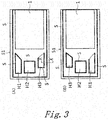
- the distribution holes H1 to H3 as illustrated in FIG. 3 have the same function as those illustrated in FIG. 1 and FIG. 2 although they have different shapes.
- the gas sealings S (bold lines) are provided along the edge except for a side of the distribution hole H3 for discharging the anode gas so as not to prevent distribution of the anode gas.
- an opening (discontinued part) for distributing the anode gas is formed in the gas sealings S at a suitable part of the edge of the distribution hole H3.
- the gas sealings S are provided along the edge except for a side of the distribution hole H1 for supplying the cathode gas so as not to prevent distribution of the cathode gas.
- sealings are also provided between the single cells (between mutually opposed separators) along the edge except for respective sides of the distribution holes H2, H4 of the separators so as not to prevent distribution of the cooling fluid.
- the fuel cell stack FS including a stacked plurality of single cells C
- at least a part of the inner walls of the manifolds M3, M6 for discharging reaction gas is formed in a continuous flat shape that extends in the stacking direction of the plurality of single cells C.
- the end faces (inner walls of the distribution holes H3, H6) of the stacked members which are the frames 51 and the separators 2A, 2B, form the inner walls of the manifolds M3, M6 which are at least partly formed in a continuous flat shape that extends in the stacking direction of the plurality of single cells C. That is, the end faces of the stacked members (51, 2A, 2B) continue to be flush with each other at least in a part of the inner walls of the manifolds M3, M6.
- the fuel cell stack FS of the embodiment is installed such that the long sides of the single cells C are horizontal as illustrated in FIG. 1 .
- the flat parts of the inner walls of the manifold M3, M6 are located at the lower side with respect to the direction of gravity. In addition to the lower side, the flat parts may extend to the other sides. Further, in addition to the discharging manifolds M3, M6, the inner walls of the supplying manifolds M1, M4 may also have a flat part.
- FIG. 4 is a perspective cross sectional view taken along the line X-X in FIG. 3 , illustrating the manifold M3 for discharging the anode gas.
- the gas in the manifold M3 flows downward as illustrated by the arrow in FIG. 4 (A) , but the gas flows in the horizontal direction when the fuel cell stack FS is positioned as described above in FIG. 1 .
- the frames 51 and the separators 2A, 2B of the single cells C have flattening faces F1, F2, F3 in the inner walls of the respective distribution holes H3.
- the flattening faces F1, F2, F3 continue to be flush with each other so that at least a part of the inner wall of the manifold M3 is formed in a continuous flat shape that extends in the stacking direction of the single cells C.
- the frames 51 include integrally formed respective ribs 21 that protrude from the cathode side (lower side in FIG. 4 ) along the inner peripheries of the distribution holes H3, and the inner walls of the distribution holes H3 including the ribs 21 forms the flattening faces F1. Further, the inner walls of the distribution holes H3 of the separators 2A, 2B respectively form the flattening faces F2, F3.
- gas sealings S are provided between the edges of the respective distribution holes H3 of the anode separators 2A and the frames 51, between the edges of the respective distribution holes H3 of the frames 51 and the cathode separators 2B and between the edges of the cathode separators 2B and the anode separators 2A of adjacent single cells C.
- the gas sealings are provided between the top faces of the ribs 21 and the cathode separators 2B,
- the above-described openings for distributing the cathode gas can be formed by partly removing the ribs 21.
- FIG. 4 illustrates the manifold M3 for discharging the anode gas as an example, it should be understood that the other manifolds M1, M4, M6 for the reaction gas may have the same configuration.
- each of the single cells C generates electric power by electrochemical reaction when the anode gas and the cathode gas are supplied respectively to the anode electrode layer and the cathode electrode layer of the membrane electrode assembly 1.
- water is generated.
- the generated water is discharged mainly through the manifolds M3, M6 for discharging the reaction gas.
- the end faces of the stacked members which are the frames 51 and the separators 2A, 2B, form the inner wall of the manifold M3, at least a part of which is formed in a continuous flat shape that extends in the stacking direction of the single cells C without any gaps.
- the frames 51 and the separators 2A, 2B respectively have the flattening faces F1 to F3 in the inner walls of the distribution holes H3, and the flattening faces F1 to F3 continues to each other to be flash in the same flat face so that at least a part of the inner wall of the manifold M3 is formed in a continuous flat shape that extends in the stacking direction of the single cells C.
- the fuel cell stack FS can suitably discharge the generated water through the manifold M3 without a decrease of the flowability of the reaction gas and an increase of the production cost. Further, in the fuel cell stack FS, the good drainage can prevent corrosion of the stacked members (51, 2A, 2B) due to the retained generated water even though the end faces (i.e. the flattening faces F1 to F3) of the stacked members, which are frames 51 and the separators 2A, 2B, are exposed in the inner wall of the manifold M3.
- the generated water can be smoothly and rapidly discharged since the part formed in a flat shape in the inner wall of the manifold M3 is at least in the lower side of the inner wall of the manifold M3 with respect to the direction of gravity.
- FIG. 5 illustrates a fuel cell according to a second embodiment of the present invention, which is a perspective cross sectional view and an enlarged cross sectional view taken along the line X-X in FIG. 3 as with the FIG. 4 . That is, FIG. 5 illustrates a manifold M3 for discharging anode gas.
- the same reference signs are denoted to the same components as those of the first embodiment, and the detailed description thereof is omitted.
- frames 51 of single cells C include respective ribs 21 that is disposed in the inner walls (edges) of distribution holes H3 and protrude at least from one side of the frames 51 to cover the inner walls of the distribution holes H3 of separators 2A, 2B, and respective flattening faces F1 that include the side walls of the ribs 21.
- the frames 51 of the illustrated example integrally include the ribs 21 that protrude towards the cathode side (lower side in FIG. 5 ).
- the flattening faces F1 of the frames 51 continue to be flush with each other so that at least a part of the inner wall of the manifold M3 is formed in a gapless continuous flat shape that extends in the stacking direction of the single cells C. That is, while the flattening faces F1 to F3 of the frames 51 and the separators 2A, 2B form the flat face of the manifold M3 in the previously-described first embodiment, only the flattening faces F1 of the frames 51 form the flat face of the manifold M3 in this embodiment.
- this fuel cell stack FS can suitably discharge generated water through the manifold M3 without a decrease of the flowability of reaction gas and an increase of the production cost. Further, since the ribs 21 of the resin frames 51 cover the inner walls of the distribution holes H3 of the metal separators 2A, 2B, generated water does not come in contact with these inner walls. This can impart a function of sufficiently protecting the inner walls against corrosion to the fuel cell stack FS.
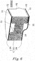
- FIG. 6 illustrates a fuel cell stack according to a third embodiment of the present invention, which is a cross sectional view of a distribution hole of a single cell taken along the line X-X in FIG. 3 .
- a frame 51 of the single cell C of FIG. 6 includes integrally formed ribs 21, 21 that protrude from both sides of the frame 51 in the inner wall (edge) of a distribution hole H3, and the inner wall including the side walls of the ribs 21, 21 forms a flattening face F1.
- the single cell C includes adhesive portions in the edge of the distribution hole H3 of the frame 51 for adhesion to the opposed members adjacent in the stacking direction and pits for adhesive 22 on the opposite side of the adhesive portions from the distribution hole.
- the adhesive 22 is applied on the adhesive portions and serves as sealing after curing,
- the adhesive portions are equivalent of the above-described gas sealings (see FIG. 3 ) and correspond to the top faces of the ribs 21 in the illustrated example.
- the opposed members adjacent in the stacking direction are anode and cathode separators 2A, 2B.
- the fuel cell stack in which a plurality of fuel cells C with the above-described configuration is stacked, can suitably discharge generated water through the manifold M3 without a decrease of the flowability of reaction gas and an increase of the production cost. Furthermore, the gaps between the frames 51 and the separators 2A, 2B are completely filled with the adhesive 22, and the pits 23 can release excess adhesive 22 to prevent it from being extruded to the distribution holes H3. Therefore, the inner wall of the manifold M3 can be formed in a flat shape.
- FIG. 7 illustrates a fuel cell stack according to a third embodiment of the present invention, which is a cross sectional view of a distribution hole of a single cell taken along the line X-X in FIG. 3 .
- a frame 51 of the single cell C of FIG. 7 includes integrally formed ribs 21, 21 that protrude from both sides of the frame 51 in the inner wall (edge) of the distribution hole H3, and the inner wall including the side walls of the ribs 21, 21 forms a flattening face F1.
- the single cell C includes adhesive portions in the edge of the distribution hole H3 of the frame 51 for adhesion to the opposed members (separators 2A, 2B) adjacent in the stacking direction and pits 23 for adhesive 22 on the opposite side of the adhesive portions 22 from the distribution hole H3. Further, the adhesive portions have inclined faces 24 that form downward slopes to the pits 23.
- the fuel cell stack in which a plurality of single cells C with the above-described configuration is stacked, can suitably discharge generated water through the manifold M3 without a decrease of the flowability of reaction gas and an increase of the production cost. Furthermore, the gaps between the frames 51 and the separators 2A, 2B are completely filled with the adhesive 22, and the inclined faces 24 can actively release excess adhesive 22 to the pits 23. This can prevent extrusion of the adhesive 22 to the distribution holes H3 more reliably, and the inner wall of the manifold M3 can therefore be formed in a flat shape.
- the configuration of the fuel cell stack of the present invention is not limited to the above-described embodiments.
- the details of the configuration can be suitably changed, or the configurations of the above-described embodiments can be suitable combined without departing from the features of the present invention.
Landscapes
- Life Sciences & Earth Sciences (AREA)
- Engineering & Computer Science (AREA)
- Manufacturing & Machinery (AREA)
- Sustainable Development (AREA)
- Sustainable Energy (AREA)
- Chemical & Material Sciences (AREA)
- Chemical Kinetics & Catalysis (AREA)
- Electrochemistry (AREA)
- General Chemical & Material Sciences (AREA)
- Fuel Cell (AREA)
Abstract
Description
- The present invention relates to an improvement of fuel cells such as polymer electrolyte fuel cells, in particular to a fuel cell stack in which a plurality of single cells each including a membrane electrode assembly and a pair of separators is stacked.
- For example, one of such fuel cell stacks in the art is described in
Patent Document 1. The fuel cell stack described inPatent Document 1 includes electrolyte-electrode assemblies and metal separators that are alternately stacked in the horizontal direction, in which fluid communication holes for distributing coolant or reaction gas penetrate in the stacking direction. Further, the fuel cell stack is configured such that insulative members are provided to the metal separators to cover the surfaces of the metal separators and the inner walls of the fluid communication holes so that the sealing property against the coolant or the reaction gas is secured by means of the insulative members. - Patent Document 1:
JP 4551746B - In fuel cell stacks as describe above, water is generated along with power generation, and a fluid discharging communication hole is used also as a route for discharging the generated water among the fluid communication holes formed in the stacking direction. However, a problem with the conventional fuel cell stack is that the generated water is likely to be retained inside the fluid communication hole since the fluid communication holes have uneven inner walls due to the gaps between the layers, and it has been required to solve the problem.
- For example, a possible measure for preventing such retention of the generated water in the fluid communication hole is to cover the entire inner wall of the fluid communication hole with an insulative member. However, this results in the high production cost. Further, the flow area is changed depending on the temperature and the compression condition of the insulative member, which may have a negative influence on the pressure loss of the channel and the distribution of fluid to each single cell.
- The present invention has been made in view of the above-described problem with the prior art, and an object thereof is to provide a fuel cell stack that includes a manifold for distributing reaction gas in the stacking direction and that can suitably discharge generated water through the manifold without a decrease of the flowability of the reaction gas and an increase of the production cost.
- The fuel cell stack according to the present invention includes a stacked plurality of single cells, each of the single cells having a membrane electrode assembly with a peripheral frame and a pair of separators that hold the peripheral frame and the membrane electrode assembly between them. Further, the fuel cell stack is configured such that the peripheral frames and separators of the single cells have respective distribution holes that continue to each other in the stacked state to form a manifold for distributing reaction gas, and at least a part of the inner wall of the manifold is formed in a continuous flat shape that extends in the stacking direction of the plurality of single cells.
- The fuel cell stack according to the present invention includes the manifold for the reaction gas in the stacking direction, in which at least a part of the inner wall of the manifold is formed in a gapless continuous flat shape extending in the stacking direction of the single cells by the end faces (the inner walls of the distribution holes) of the stacked members such as the frames and the separators without any special member. That is, the end faces of the stacked members continue to be flush with each other at least in a part of the inner wall of the manifold.
- With this configuration, the fuel cell stack can suitably discharge generated water through the manifold without a decrease of the flowability of the reaction gas and an increase of the production cost. Further, since the fuel cell stack exhibits good water drainage, corrosion of the stacked members such as the frames and the separators due to the retained generated water can be prevented even when the end faces of the stacked members are exposed in the inner wall of the manifold.
-
-
FIG. 1 is (A) a perspective view of a fuel cell stack according to a first embodiment of the present invention in a disassembled state and (B) a perspective view thereof in an assembled state. -
FIG. 2 is (A) a plan view of a single cell of the fuel cell stack inFIG. 1 in a disassembled state and (B) a plan view thereof in an assembled state. -
FIG. 3 is (A) a partial plan view of the anode side of a membrane electrode assembly and (B) a partial plan view of the cathode side of the membrane electrode assembly. -
FIG. 4 is (A) a perspective cross sectional view of the main part of a fuel cell stack taken along the line X-X inFIG. 3 and (B) an enlarged cross sectional view of a distribution hole. -
FIG. 5 is (A) a perspective cross sectional view of the main part of a fuel cell stack according to a second embodiment of the present invention and (B) an enlarged cross sectional view of a distribution hole. -
FIG. 6 is a perspective cross sectional view of the main part of a fuel cell stack according to a third embodiment of the present invention. -
FIG. 7 is a perspective cross sectional view of the main part of a fuel cell stack according to a fourth embodiment of the present invention. -
FIG. 1 to FIG. 4 illustrate a fuel cell stack according to a first embodiment of the present invention.
The fuel celt stack FS inFIG. 1 (A) includes anend plate 56A that is disposed at one end (right end inFIG. 1 ) in the stacking direction of a stack A of single cells C via acurrent collector plate 54A and aspacer 55, and anend plate 56B that is disposed at the other end via acurrent collector plate 54B. The fuel cell stack FS further includesfastening plates FIG. 1 ) of the stack A corresponding to the long sides of the single cells C, and reinforcingplates - In the fuel cell stack FS, the
fastening plates reinforcing plates end plates FIG. 1 (B) , which restrains and presses the stack A in the stacking direction to apply a predetermined contact surface pressure to each of the single cells C, so that the gas sealing property, the electrical conductivity and the like are maintained at high level. - As illustrated in
FIG. 2 , each of the single cells C includes amembrane electrode assembly 1 with aperipheral frame 51, a pair ofseparators frame 51 and themembrane electrode assembly 1 between them, in which anode and cathode gas channels are formed between theframe 51 and themembrane electrode assembly 1 and therespective separators - The
membrane electrode assembly 1, which is generally referred to as an MEA, has a structure known in the art in which an electrolyte layer of a solid polymer is intervened between an anode electrode layer and a cathode electrode layer although the detailed structure is not shown in the figure. - The
frame 51 is integrally formed with themembrane electrode assembly 1 by resin molding (e.g. injection molding). In the embodiment, theframe 51 has a rectangular shape, and themembrane electrode assembly 1 is disposed at the center thereof. Further, theframe 51 has distribution holes H1 to H3, H4 to H6 for distributing reaction gas, which are disposed such that three holes are arranged at both short sides. - The
separators 2A, 3B are constituted by rectangular metal plate members having approximately the same length and width as the frame 5. For example, theseparators 2A, 3B are made of stainless steel, and one plate has inverted faces to those of the other plate. In the illustrated example, theseparators membrane electrode assembly 1. The uneven shape of theseparators membrane electrode assembly 1 while the recesses of the corrugation form the anode and cathode gas channels between theseparators membrane electrode assembly 1. Further, theseparators frame 51. - The above-described
membrane electrode assembly 1 with theframe 51 and theseparators frame 51 and theseparators - In the single cell C in
FIG. 2 (B) , the manifolds M1 to M3 at one end, which is the left side in the figure, are configured respectively to supply cathode gas (M1), to supply the cooling fluid (M2) and to discharge anode gas (M3) in the descending order. Further, in the single cell C, the manifolds M4 to M6 at the other end, which is the right side in the figure, are configured respectively to supply the anode gas (M4), to discharge the cooling fluid (M5) and to supply the cathode gas (M6) in the descending order. The anode gas is hydrogen-containing gas. The cathode gas is oxygen-containing gas, for example, air. The cooling fluid is, for example, water. - As illustrated in the
frame 51 and themembrane electrode assembly 1 ofFIG 3 , gas sealings S are provided to the single cell C along the edge of theframe 51 and around the distribution holes H1 to H3 to seal the gap to theseparators frame 51 and theseparators FIG. 3 have the same function as those illustrated inFIG. 1 andFIG. 2 although they have different shapes. - At the anode side as illustrated in
FIG. 3 (A) , the gas sealings S (bold lines) are provided along the edge except for a side of the distribution hole H3 for discharging the anode gas so as not to prevent distribution of the anode gas. In other words, an opening (discontinued part) for distributing the anode gas is formed in the gas sealings S at a suitable part of the edge of the distribution hole H3. - At the cathode side as illustrated in
FIG. 3 (B) , the gas sealings S (bold lines) are provided along the edge except for a side of the distribution hole H1 for supplying the cathode gas so as not to prevent distribution of the cathode gas. Although not shown in the figure, sealings are also provided between the single cells (between mutually opposed separators) along the edge except for respective sides of the distribution holes H2, H4 of the separators so as not to prevent distribution of the cooling fluid. - In the fuel cell stack FS including a stacked plurality of single cells C, at least a part of the inner walls of the manifolds M3, M6 for discharging reaction gas is formed in a continuous flat shape that extends in the stacking direction of the plurality of single cells C. To be more specific, in the fuel cell stack FS, the end faces (inner walls of the distribution holes H3, H6) of the stacked members, which are the
frames 51 and theseparators - The fuel cell stack FS of the embodiment is installed such that the long sides of the single cells C are horizontal as illustrated in
FIG. 1 . In this position, the flat parts of the inner walls of the manifold M3, M6 are located at the lower side with respect to the direction of gravity. In addition to the lower side, the flat parts may extend to the other sides. Further, in addition to the discharging manifolds M3, M6, the inner walls of the supplying manifolds M1, M4 may also have a flat part. -
FIG. 4 is a perspective cross sectional view taken along the line X-X inFIG. 3 , illustrating the manifold M3 for discharging the anode gas. The gas in the manifold M3 flows downward as illustrated by the arrow inFIG. 4 (A) , but the gas flows in the horizontal direction when the fuel cell stack FS is positioned as described above inFIG. 1 . - In the embodiment, as illustrated in the enlarged cross section of
FIG. 4 (B) , theframes 51 and theseparators - To be more specific, the
frames 51 include integrally formedrespective ribs 21 that protrude from the cathode side (lower side inFIG. 4 ) along the inner peripheries of the distribution holes H3, and the inner walls of the distribution holes H3 including theribs 21 forms the flattening faces F1. Further, the inner walls of the distribution holes H3 of theseparators - The above-described gas sealings S are provided between the edges of the respective distribution holes H3 of the
anode separators 2A and theframes 51, between the edges of the respective distribution holes H3 of theframes 51 and thecathode separators 2B and between the edges of thecathode separators 2B and theanode separators 2A of adjacent single cells C. - Since the illustrated example of the fuel cell stack FS includes the
ribs 21 that protrude from the cathode side of theframes 51, the gas sealings are provided between the top faces of theribs 21 and thecathode separators 2B, The above-described openings for distributing the cathode gas can be formed by partly removing theribs 21. WhileFIG. 4 illustrates the manifold M3 for discharging the anode gas as an example, it should be understood that the other manifolds M1, M4, M6 for the reaction gas may have the same configuration. - In the fuel cell stack FS with the above-described configuration, each of the single cells C generates electric power by electrochemical reaction when the anode gas and the cathode gas are supplied respectively to the anode electrode layer and the cathode electrode layer of the
membrane electrode assembly 1. Along with the power generation, water is generated. The generated water is discharged mainly through the manifolds M3, M6 for discharging the reaction gas. - In this regard, in the fuel cell stack FS, the end faces of the stacked members, which are the
frames 51 and theseparators - Particularly in the fuel stack FS of the embodiment, the
frames 51 and theseparators - With this configuration, the fuel cell stack FS can suitably discharge the generated water through the manifold M3 without a decrease of the flowability of the reaction gas and an increase of the production cost. Further, in the fuel cell stack FS, the good drainage can prevent corrosion of the stacked members (51, 2A, 2B) due to the retained generated water even though the end faces (i.e. the flattening faces F1 to F3) of the stacked members, which are
frames 51 and theseparators - In the fuel cell stack FS of the embodiment, the generated water can be smoothly and rapidly discharged since the part formed in a flat shape in the inner wall of the manifold M3 is at least in the lower side of the inner wall of the manifold M3 with respect to the direction of gravity.
-
FIG. 5 illustrates a fuel cell according to a second embodiment of the present invention, which is a perspective cross sectional view and an enlarged cross sectional view taken along the line X-X inFIG. 3 as with theFIG. 4 . That is,FIG. 5 illustrates a manifold M3 for discharging anode gas. In the second to fourth embodiments inFIG. 5 to FIG. 7 , the same reference signs are denoted to the same components as those of the first embodiment, and the detailed description thereof is omitted. - In the fuel cell stack FS in
FIG. 5 , frames 51 of single cells C includerespective ribs 21 that is disposed in the inner walls (edges) of distribution holes H3 and protrude at least from one side of theframes 51 to cover the inner walls of the distribution holes H3 ofseparators ribs 21. Theframes 51 of the illustrated example integrally include theribs 21 that protrude towards the cathode side (lower side inFIG. 5 ). - In the fuel cell stack FS, the flattening faces F1 of the
frames 51 continue to be flush with each other so that at least a part of the inner wall of the manifold M3 is formed in a gapless continuous flat shape that extends in the stacking direction of the single cells C. That is, while the flattening faces F1 to F3 of theframes 51 and theseparators frames 51 form the flat face of the manifold M3 in this embodiment. - As with the first embodiment, this fuel cell stack FS can suitably discharge generated water through the manifold M3 without a decrease of the flowability of reaction gas and an increase of the production cost. Further, since the
ribs 21 of the resin frames 51 cover the inner walls of the distribution holes H3 of themetal separators -
FIG. 6 illustrates a fuel cell stack according to a third embodiment of the present invention, which is a cross sectional view of a distribution hole of a single cell taken along the line X-X inFIG. 3 . - A
frame 51 of the single cell C ofFIG. 6 includes integrally formedribs frame 51 in the inner wall (edge) of a distribution hole H3, and the inner wall including the side walls of theribs - The single cell C includes adhesive portions in the edge of the distribution hole H3 of the
frame 51 for adhesion to the opposed members adjacent in the stacking direction and pits for adhesive 22 on the opposite side of the adhesive portions from the distribution hole. - The adhesive 22 is applied on the adhesive portions and serves as sealing after curing, The adhesive portions are equivalent of the above-described gas sealings (see
FIG. 3 ) and correspond to the top faces of theribs 21 in the illustrated example. The opposed members adjacent in the stacking direction are anode andcathode separators pits 23, which are recesses in theframe 51 formed in a groove shape, allow to release excess adhesive 22 when theseparators - As with the previously-described embodiments, the fuel cell stack, in which a plurality of fuel cells C with the above-described configuration is stacked, can suitably discharge generated water through the manifold M3 without a decrease of the flowability of reaction gas and an increase of the production cost. Furthermore, the gaps between the
frames 51 and theseparators pits 23 can release excess adhesive 22 to prevent it from being extruded to the distribution holes H3. Therefore, the inner wall of the manifold M3 can be formed in a flat shape. -
FIG. 7 illustrates a fuel cell stack according to a third embodiment of the present invention, which is a cross sectional view of a distribution hole of a single cell taken along the line X-X inFIG. 3 . - A
frame 51 of the single cell C ofFIG. 7 includes integrally formedribs frame 51 in the inner wall (edge) of the distribution hole H3, and the inner wall including the side walls of theribs - The single cell C includes adhesive portions in the edge of the distribution hole H3 of the
frame 51 for adhesion to the opposed members (separators adhesive portions 22 from the distribution hole H3. Further, the adhesive portions have inclined faces 24 that form downward slopes to thepits 23. - As with the previously-described embodiments, the fuel cell stack, in which a plurality of single cells C with the above-described configuration is stacked, can suitably discharge generated water through the manifold M3 without a decrease of the flowability of reaction gas and an increase of the production cost. Furthermore, the gaps between the
frames 51 and theseparators pits 23. This can prevent extrusion of the adhesive 22 to the distribution holes H3 more reliably, and the inner wall of the manifold M3 can therefore be formed in a flat shape. - The configuration of the fuel cell stack of the present invention is not limited to the above-described embodiments. The details of the configuration can be suitably changed, or the configurations of the above-described embodiments can be suitable combined without departing from the features of the present invention.
-
- 1
- Membrane electrode assembly
- 2A, 2B
- Separator
- 21
- Rib
- 22
- Adhesive
- 23
- Pit
- 24
- Inclined face
- 51
- Frame
- C
- Single cell
- FS
- Fuel cell stack
- F1
- Flattening face of frame
- F2, F3
- Flattening face of separator
- H1 to H6
- Distribution hole
- M1
- Manifold for supplying cathode gas
- M3
- Manifold for discharging anode gas
- M4
- Manifold for supplying anode gas
- M6
- Manifold for discharging cathode gas
Claims (6)
- A fuel cell stack, which comprises a stacked plurality of single cells, each of the single cells having a membrane electrode assembly with a peripheral frame and a pair of separators holding the peripheral frame and the membrane electrode assembly between them,
wherein the peripheral frame and the separators of each of the single cells have distribution holes that continue to each other in a stacked state to form a manifold for distributing reaction gas, and
at least a part of an inner wall of the manifold is formed in a continuous flat shape that extends in a stacking direction of the single cells. - The fuel cell stack according to claim 1, wherein each of the peripheral frames and each of the separators comprise a flattening face in an inner wall of the respective distribution hole, and
each of the flattening face continues to each other so that at least a part of the inner wall of the manifold is formed in the continuous flat shape that extends in the stacking direction of the single cells. - The fuel cell stack according to claim 1, wherein each of the peripheral flames comprises a rib that is disposed in the inner wall of each of the distribution holes and that protrudes at least from one side of the peripheral frame to cover the inner wall of the distribution hole of the separator, and a flattening face that includes a side wall of the rib, and
the flattening faces of each of the peripheral frames continue to each other so that at least a part of the inner wall of the manifold is formed in the continuous flat shape that extends in the stacking direction of the single cells. - The fuel cell stack according to any one of claims 1 to 3, wherein the flat part of the inner wall of the manifold extends at least in a lower side with respect to a direction of gravity.
- The fuel cell stack according to any one of claims 1 to 4, wherein each of the peripheral frames comprises a adhesive portion for adhesion to an opposed member adjacent in the stacking direction at an edge of each of the distribution holes and a pit for adhesive on an opposite side of the adhesive portion from the distribution hole.
- The fuel cell stack according to claim 5, wherein the adhesive portion comprises an inclined face that forms a downward slope to the pit.
Applications Claiming Priority (1)
| Application Number | Priority Date | Filing Date | Title |
|---|---|---|---|
| PCT/JP2015/063753 WO2016181522A1 (en) | 2015-05-13 | 2015-05-13 | Fuel cell stack |
Publications (3)
| Publication Number | Publication Date |
|---|---|
| EP3297080A1 true EP3297080A1 (en) | 2018-03-21 |
| EP3297080A4 EP3297080A4 (en) | 2018-05-30 |
| EP3297080B1 EP3297080B1 (en) | 2020-12-23 |
Family
ID=57249070
Family Applications (1)
| Application Number | Title | Priority Date | Filing Date |
|---|---|---|---|
| EP15891846.6A Not-in-force EP3297080B1 (en) | 2015-05-13 | 2015-05-13 | Fuel cell stack |
Country Status (7)
| Country | Link |
|---|---|
| US (1) | US10312528B2 (en) |
| EP (1) | EP3297080B1 (en) |
| JP (1) | JP6395121B2 (en) |
| KR (1) | KR101963998B1 (en) |
| CN (1) | CN107534178B (en) |
| CA (1) | CA2985885C (en) |
| WO (1) | WO2016181522A1 (en) |
Families Citing this family (1)
| Publication number | Priority date | Publication date | Assignee | Title |
|---|---|---|---|---|
| JP6607411B2 (en) * | 2015-11-06 | 2019-11-20 | 日産自動車株式会社 | Fuel cell single cell structure and fuel cell stack structure in which the fuel cell single cells are stacked |
Family Cites Families (18)
| Publication number | Priority date | Publication date | Assignee | Title |
|---|---|---|---|---|
| US5045413A (en) | 1989-05-03 | 1991-09-03 | Institute Of Gas Technology | Fully internal mainfolded fuel cell stack |
| US6613470B1 (en) | 1999-09-01 | 2003-09-02 | Honda Giken Kogyo Kabushiki Kaisha | Solid polymer electrolyte fuel cell stack |
| JP4151314B2 (en) | 2001-06-18 | 2008-09-17 | トヨタ自動車株式会社 | Fuel cell |
| JP4993828B2 (en) | 2001-09-06 | 2012-08-08 | 株式会社日本自動車部品総合研究所 | Fuel cell |
| JP2004192893A (en) * | 2002-12-10 | 2004-07-08 | Toyota Motor Corp | Stacked fuel cell, stacked fuel cell manufacturing method, and stacked fuel cell manufacturing apparatus |
| JP2004213972A (en) * | 2002-12-27 | 2004-07-29 | Hitachi Ltd | Stacked fuel cell |
| JP4551746B2 (en) | 2004-11-24 | 2010-09-29 | 本田技研工業株式会社 | Fuel cell stack |
| FR2887686B1 (en) | 2005-06-28 | 2010-08-13 | Peugeot Citroen Automobiles Sa | SEAL AND FUEL CELL COMPRISING SUCH A SEAL APPOSE TO BIPOLAR PLATES |
| JP2007250232A (en) * | 2006-03-14 | 2007-09-27 | Equos Research Co Ltd | Fuel cell stack |
| US7709123B2 (en) | 2006-06-16 | 2010-05-04 | Panasonic Corporation | Film electrode assembly for fuel cell, polymer electrolytic cell for fuel cell and method for manufacturing polymer electrolytic fuel cell and film electrode assembly |
| JP5146899B2 (en) * | 2006-10-24 | 2013-02-20 | トヨタ自動車株式会社 | Fuel cell |
| JP5286895B2 (en) * | 2008-04-04 | 2013-09-11 | トヨタ自動車株式会社 | Single cell assembly and fuel cell |
| JP5353558B2 (en) * | 2009-08-21 | 2013-11-27 | トヨタ自動車株式会社 | Fuel cell stack |
| KR101154396B1 (en) | 2009-11-27 | 2012-06-15 | 현대자동차주식회사 | Separator of fuel cell stack for vehicle |
| EP2579376B1 (en) * | 2010-06-01 | 2017-04-19 | Nissan Motor Co., Ltd | Fuel cell |
| JP5666396B2 (en) * | 2011-07-14 | 2015-02-12 | 本田技研工業株式会社 | Manufacturing method of metal separator for fuel cell |
| JP5773232B2 (en) * | 2012-03-21 | 2015-09-02 | 日産自動車株式会社 | Fuel cell |
| US10644329B2 (en) | 2012-12-26 | 2020-05-05 | Nissan Motor Co., Ltd. | Fuel cell stack having a displacement absorbing member disposed in a cooling fluid channel |
-
2015
- 2015-05-13 KR KR1020177032591A patent/KR101963998B1/en not_active Expired - Fee Related
- 2015-05-13 CN CN201580079953.4A patent/CN107534178B/en not_active Expired - Fee Related
- 2015-05-13 JP JP2017517538A patent/JP6395121B2/en not_active Expired - Fee Related
- 2015-05-13 WO PCT/JP2015/063753 patent/WO2016181522A1/en not_active Ceased
- 2015-05-13 EP EP15891846.6A patent/EP3297080B1/en not_active Not-in-force
- 2015-05-13 CA CA2985885A patent/CA2985885C/en active Active
- 2015-05-13 US US15/573,296 patent/US10312528B2/en active Active
Also Published As
| Publication number | Publication date |
|---|---|
| KR101963998B1 (en) | 2019-03-29 |
| WO2016181522A1 (en) | 2016-11-17 |
| JPWO2016181522A1 (en) | 2018-03-08 |
| CA2985885A1 (en) | 2016-11-17 |
| CN107534178A (en) | 2018-01-02 |
| US20180138524A1 (en) | 2018-05-17 |
| CN107534178B (en) | 2019-01-22 |
| US10312528B2 (en) | 2019-06-04 |
| EP3297080B1 (en) | 2020-12-23 |
| EP3297080A4 (en) | 2018-05-30 |
| JP6395121B2 (en) | 2018-09-26 |
| CA2985885C (en) | 2019-07-30 |
| KR20170129272A (en) | 2017-11-24 |
Similar Documents
| Publication | Publication Date | Title |
|---|---|---|
| US9799898B2 (en) | Fuel cell | |
| US20140011111A1 (en) | Membrane electrode assembly for fuel cell | |
| US9214682B2 (en) | Fuel cell | |
| CA2728953C (en) | Fuel cell assembly having embossed separator plates | |
| US9812728B2 (en) | Fuel-cell single cell | |
| CN110197913A (en) | Generate electricity monocell | |
| US20170200957A1 (en) | Fuel cell assemblies with improved reactant flow | |
| KR20110013963A (en) | Separator for Fuel Cell | |
| US20120258377A1 (en) | Fuel cell | |
| US9559376B2 (en) | Fuel cell with an electrolyte membrane and gas diffusion layers | |
| EP2830130B1 (en) | Fuel cell | |
| CN108933272A (en) | Fuel cell pack | |
| EP3297081B1 (en) | Fuel cell stack | |
| EP3361543B1 (en) | Fuel cell stack | |
| CA2985885C (en) | Fuel cell stack | |
| US10103391B2 (en) | Fuel cell seal | |
| US9595722B2 (en) | Fuel cell plate and fuel cell | |
| GB2525951A (en) | Bipolar plate assembly, fuel cell system and vehicle | |
| JP2013222698A (en) | Fuel cell | |
| EP3419091B1 (en) | Unit cell structure for fuel cell |
Legal Events
| Date | Code | Title | Description |
|---|---|---|---|
| STAA | Information on the status of an ep patent application or granted ep patent |
Free format text: STATUS: THE INTERNATIONAL PUBLICATION HAS BEEN MADE |
|
| PUAI | Public reference made under article 153(3) epc to a published international application that has entered the european phase |
Free format text: ORIGINAL CODE: 0009012 |
|
| STAA | Information on the status of an ep patent application or granted ep patent |
Free format text: STATUS: REQUEST FOR EXAMINATION WAS MADE |
|
| 17P | Request for examination filed |
Effective date: 20171205 |
|
| AK | Designated contracting states |
Kind code of ref document: A1 Designated state(s): AL AT BE BG CH CY CZ DE DK EE ES FI FR GB GR HR HU IE IS IT LI LT LU LV MC MK MT NL NO PL PT RO RS SE SI SK SM TR |
|
| AX | Request for extension of the european patent |
Extension state: BA ME |
|
| A4 | Supplementary search report drawn up and despatched |
Effective date: 20180503 |
|
| RIC1 | Information provided on ipc code assigned before grant |
Ipc: H01M 8/0273 20160101ALI20180423BHEP Ipc: H01M 8/2483 20160101ALI20180423BHEP Ipc: H01M 8/24 20160101AFI20180423BHEP Ipc: H01M 8/242 20160101ALI20180423BHEP Ipc: H01M 8/02 20160101ALI20180423BHEP |
|
| DAV | Request for validation of the european patent (deleted) | ||
| DAX | Request for extension of the european patent (deleted) | ||
| STAA | Information on the status of an ep patent application or granted ep patent |
Free format text: STATUS: EXAMINATION IS IN PROGRESS |
|
| 17Q | First examination report despatched |
Effective date: 20190910 |
|
| GRAP | Despatch of communication of intention to grant a patent |
Free format text: ORIGINAL CODE: EPIDOSNIGR1 |
|
| STAA | Information on the status of an ep patent application or granted ep patent |
Free format text: STATUS: GRANT OF PATENT IS INTENDED |
|
| INTG | Intention to grant announced |
Effective date: 20201013 |
|
| GRAS | Grant fee paid |
Free format text: ORIGINAL CODE: EPIDOSNIGR3 |
|
| GRAA | (expected) grant |
Free format text: ORIGINAL CODE: 0009210 |
|
| STAA | Information on the status of an ep patent application or granted ep patent |
Free format text: STATUS: THE PATENT HAS BEEN GRANTED |
|
| AK | Designated contracting states |
Kind code of ref document: B1 Designated state(s): AL AT BE BG CH CY CZ DE DK EE ES FI FR GB GR HR HU IE IS IT LI LT LU LV MC MK MT NL NO PL PT RO RS SE SI SK SM TR |
|
| REG | Reference to a national code |
Ref country code: GB Ref legal event code: FG4D |
|
| REG | Reference to a national code |
Ref country code: DE Ref legal event code: R096 Ref document number: 602015063995 Country of ref document: DE |
|
| REG | Reference to a national code |
Ref country code: AT Ref legal event code: REF Ref document number: 1348602 Country of ref document: AT Kind code of ref document: T Effective date: 20210115 |
|
| REG | Reference to a national code |
Ref country code: IE Ref legal event code: FG4D |
|
| PG25 | Lapsed in a contracting state [announced via postgrant information from national office to epo] |
Ref country code: NO Free format text: LAPSE BECAUSE OF FAILURE TO SUBMIT A TRANSLATION OF THE DESCRIPTION OR TO PAY THE FEE WITHIN THE PRESCRIBED TIME-LIMIT Effective date: 20210323 Ref country code: RS Free format text: LAPSE BECAUSE OF FAILURE TO SUBMIT A TRANSLATION OF THE DESCRIPTION OR TO PAY THE FEE WITHIN THE PRESCRIBED TIME-LIMIT Effective date: 20201223 Ref country code: FI Free format text: LAPSE BECAUSE OF FAILURE TO SUBMIT A TRANSLATION OF THE DESCRIPTION OR TO PAY THE FEE WITHIN THE PRESCRIBED TIME-LIMIT Effective date: 20201223 Ref country code: GR Free format text: LAPSE BECAUSE OF FAILURE TO SUBMIT A TRANSLATION OF THE DESCRIPTION OR TO PAY THE FEE WITHIN THE PRESCRIBED TIME-LIMIT Effective date: 20210324 |
|
| REG | Reference to a national code |
Ref country code: AT Ref legal event code: MK05 Ref document number: 1348602 Country of ref document: AT Kind code of ref document: T Effective date: 20201223 |
|
| REG | Reference to a national code |
Ref country code: NL Ref legal event code: MP Effective date: 20201223 |
|
| PG25 | Lapsed in a contracting state [announced via postgrant information from national office to epo] |
Ref country code: BG Free format text: LAPSE BECAUSE OF FAILURE TO SUBMIT A TRANSLATION OF THE DESCRIPTION OR TO PAY THE FEE WITHIN THE PRESCRIBED TIME-LIMIT Effective date: 20210323 Ref country code: SE Free format text: LAPSE BECAUSE OF FAILURE TO SUBMIT A TRANSLATION OF THE DESCRIPTION OR TO PAY THE FEE WITHIN THE PRESCRIBED TIME-LIMIT Effective date: 20201223 Ref country code: LV Free format text: LAPSE BECAUSE OF FAILURE TO SUBMIT A TRANSLATION OF THE DESCRIPTION OR TO PAY THE FEE WITHIN THE PRESCRIBED TIME-LIMIT Effective date: 20201223 |
|
| PG25 | Lapsed in a contracting state [announced via postgrant information from national office to epo] |
Ref country code: NL Free format text: LAPSE BECAUSE OF FAILURE TO SUBMIT A TRANSLATION OF THE DESCRIPTION OR TO PAY THE FEE WITHIN THE PRESCRIBED TIME-LIMIT Effective date: 20201223 Ref country code: HR Free format text: LAPSE BECAUSE OF FAILURE TO SUBMIT A TRANSLATION OF THE DESCRIPTION OR TO PAY THE FEE WITHIN THE PRESCRIBED TIME-LIMIT Effective date: 20201223 |
|
| REG | Reference to a national code |
Ref country code: LT Ref legal event code: MG9D |
|
| PG25 | Lapsed in a contracting state [announced via postgrant information from national office to epo] |
Ref country code: SM Free format text: LAPSE BECAUSE OF FAILURE TO SUBMIT A TRANSLATION OF THE DESCRIPTION OR TO PAY THE FEE WITHIN THE PRESCRIBED TIME-LIMIT Effective date: 20201223 Ref country code: LT Free format text: LAPSE BECAUSE OF FAILURE TO SUBMIT A TRANSLATION OF THE DESCRIPTION OR TO PAY THE FEE WITHIN THE PRESCRIBED TIME-LIMIT Effective date: 20201223 Ref country code: EE Free format text: LAPSE BECAUSE OF FAILURE TO SUBMIT A TRANSLATION OF THE DESCRIPTION OR TO PAY THE FEE WITHIN THE PRESCRIBED TIME-LIMIT Effective date: 20201223 Ref country code: CZ Free format text: LAPSE BECAUSE OF FAILURE TO SUBMIT A TRANSLATION OF THE DESCRIPTION OR TO PAY THE FEE WITHIN THE PRESCRIBED TIME-LIMIT Effective date: 20201223 Ref country code: SK Free format text: LAPSE BECAUSE OF FAILURE TO SUBMIT A TRANSLATION OF THE DESCRIPTION OR TO PAY THE FEE WITHIN THE PRESCRIBED TIME-LIMIT Effective date: 20201223 Ref country code: PT Free format text: LAPSE BECAUSE OF FAILURE TO SUBMIT A TRANSLATION OF THE DESCRIPTION OR TO PAY THE FEE WITHIN THE PRESCRIBED TIME-LIMIT Effective date: 20210423 Ref country code: RO Free format text: LAPSE BECAUSE OF FAILURE TO SUBMIT A TRANSLATION OF THE DESCRIPTION OR TO PAY THE FEE WITHIN THE PRESCRIBED TIME-LIMIT Effective date: 20201223 |
|
| PG25 | Lapsed in a contracting state [announced via postgrant information from national office to epo] |
Ref country code: AT Free format text: LAPSE BECAUSE OF FAILURE TO SUBMIT A TRANSLATION OF THE DESCRIPTION OR TO PAY THE FEE WITHIN THE PRESCRIBED TIME-LIMIT Effective date: 20201223 Ref country code: PL Free format text: LAPSE BECAUSE OF FAILURE TO SUBMIT A TRANSLATION OF THE DESCRIPTION OR TO PAY THE FEE WITHIN THE PRESCRIBED TIME-LIMIT Effective date: 20201223 |
|
| REG | Reference to a national code |
Ref country code: DE Ref legal event code: R097 Ref document number: 602015063995 Country of ref document: DE |
|
| PG25 | Lapsed in a contracting state [announced via postgrant information from national office to epo] |
Ref country code: IS Free format text: LAPSE BECAUSE OF FAILURE TO SUBMIT A TRANSLATION OF THE DESCRIPTION OR TO PAY THE FEE WITHIN THE PRESCRIBED TIME-LIMIT Effective date: 20210423 |
|
| PG25 | Lapsed in a contracting state [announced via postgrant information from national office to epo] |
Ref country code: IT Free format text: LAPSE BECAUSE OF FAILURE TO SUBMIT A TRANSLATION OF THE DESCRIPTION OR TO PAY THE FEE WITHIN THE PRESCRIBED TIME-LIMIT Effective date: 20201223 Ref country code: AL Free format text: LAPSE BECAUSE OF FAILURE TO SUBMIT A TRANSLATION OF THE DESCRIPTION OR TO PAY THE FEE WITHIN THE PRESCRIBED TIME-LIMIT Effective date: 20201223 |
|
| PLBE | No opposition filed within time limit |
Free format text: ORIGINAL CODE: 0009261 |
|
| STAA | Information on the status of an ep patent application or granted ep patent |
Free format text: STATUS: NO OPPOSITION FILED WITHIN TIME LIMIT |
|
| PG25 | Lapsed in a contracting state [announced via postgrant information from national office to epo] |
Ref country code: DK Free format text: LAPSE BECAUSE OF FAILURE TO SUBMIT A TRANSLATION OF THE DESCRIPTION OR TO PAY THE FEE WITHIN THE PRESCRIBED TIME-LIMIT Effective date: 20201223 |
|
| 26N | No opposition filed |
Effective date: 20210924 |
|
| REG | Reference to a national code |
Ref country code: CH Ref legal event code: PL |
|
| PG25 | Lapsed in a contracting state [announced via postgrant information from national office to epo] |
Ref country code: ES Free format text: LAPSE BECAUSE OF FAILURE TO SUBMIT A TRANSLATION OF THE DESCRIPTION OR TO PAY THE FEE WITHIN THE PRESCRIBED TIME-LIMIT Effective date: 20201223 Ref country code: CH Free format text: LAPSE BECAUSE OF NON-PAYMENT OF DUE FEES Effective date: 20210531 Ref country code: LU Free format text: LAPSE BECAUSE OF NON-PAYMENT OF DUE FEES Effective date: 20210513 Ref country code: MC Free format text: LAPSE BECAUSE OF FAILURE TO SUBMIT A TRANSLATION OF THE DESCRIPTION OR TO PAY THE FEE WITHIN THE PRESCRIBED TIME-LIMIT Effective date: 20201223 Ref country code: LI Free format text: LAPSE BECAUSE OF NON-PAYMENT OF DUE FEES Effective date: 20210531 |
|
| REG | Reference to a national code |
Ref country code: BE Ref legal event code: MM Effective date: 20210531 |
|
| PG25 | Lapsed in a contracting state [announced via postgrant information from national office to epo] |
Ref country code: SI Free format text: LAPSE BECAUSE OF FAILURE TO SUBMIT A TRANSLATION OF THE DESCRIPTION OR TO PAY THE FEE WITHIN THE PRESCRIBED TIME-LIMIT Effective date: 20201223 |
|
| PG25 | Lapsed in a contracting state [announced via postgrant information from national office to epo] |
Ref country code: IE Free format text: LAPSE BECAUSE OF NON-PAYMENT OF DUE FEES Effective date: 20210513 |
|
| PG25 | Lapsed in a contracting state [announced via postgrant information from national office to epo] |
Ref country code: IS Free format text: LAPSE BECAUSE OF FAILURE TO SUBMIT A TRANSLATION OF THE DESCRIPTION OR TO PAY THE FEE WITHIN THE PRESCRIBED TIME-LIMIT Effective date: 20210423 |
|
| PG25 | Lapsed in a contracting state [announced via postgrant information from national office to epo] |
Ref country code: BE Free format text: LAPSE BECAUSE OF NON-PAYMENT OF DUE FEES Effective date: 20210531 |
|
| PG25 | Lapsed in a contracting state [announced via postgrant information from national office to epo] |
Ref country code: HU Free format text: LAPSE BECAUSE OF FAILURE TO SUBMIT A TRANSLATION OF THE DESCRIPTION OR TO PAY THE FEE WITHIN THE PRESCRIBED TIME-LIMIT; INVALID AB INITIO Effective date: 20150513 |
|
| PG25 | Lapsed in a contracting state [announced via postgrant information from national office to epo] |
Ref country code: CY Free format text: LAPSE BECAUSE OF FAILURE TO SUBMIT A TRANSLATION OF THE DESCRIPTION OR TO PAY THE FEE WITHIN THE PRESCRIBED TIME-LIMIT Effective date: 20201223 |
|
| PGFP | Annual fee paid to national office [announced via postgrant information from national office to epo] |
Ref country code: FR Payment date: 20230420 Year of fee payment: 9 Ref country code: DE Payment date: 20230419 Year of fee payment: 9 |
|
| PGFP | Annual fee paid to national office [announced via postgrant information from national office to epo] |
Ref country code: GB Payment date: 20230420 Year of fee payment: 9 |
|
| PG25 | Lapsed in a contracting state [announced via postgrant information from national office to epo] |
Ref country code: MK Free format text: LAPSE BECAUSE OF FAILURE TO SUBMIT A TRANSLATION OF THE DESCRIPTION OR TO PAY THE FEE WITHIN THE PRESCRIBED TIME-LIMIT Effective date: 20201223 |
|
| PG25 | Lapsed in a contracting state [announced via postgrant information from national office to epo] |
Ref country code: TR Free format text: LAPSE BECAUSE OF FAILURE TO SUBMIT A TRANSLATION OF THE DESCRIPTION OR TO PAY THE FEE WITHIN THE PRESCRIBED TIME-LIMIT Effective date: 20201223 |
|
| PG25 | Lapsed in a contracting state [announced via postgrant information from national office to epo] |
Ref country code: MT Free format text: LAPSE BECAUSE OF FAILURE TO SUBMIT A TRANSLATION OF THE DESCRIPTION OR TO PAY THE FEE WITHIN THE PRESCRIBED TIME-LIMIT Effective date: 20201223 |
|
| REG | Reference to a national code |
Ref country code: DE Ref legal event code: R119 Ref document number: 602015063995 Country of ref document: DE |
|
| GBPC | Gb: european patent ceased through non-payment of renewal fee |
Effective date: 20240513 |
|
| PG25 | Lapsed in a contracting state [announced via postgrant information from national office to epo] |
Ref country code: DE Free format text: LAPSE BECAUSE OF NON-PAYMENT OF DUE FEES Effective date: 20241203 |
|
| PG25 | Lapsed in a contracting state [announced via postgrant information from national office to epo] |
Ref country code: FR Free format text: LAPSE BECAUSE OF NON-PAYMENT OF DUE FEES Effective date: 20240531 |
|
| PG25 | Lapsed in a contracting state [announced via postgrant information from national office to epo] |
Ref country code: GB Free format text: LAPSE BECAUSE OF NON-PAYMENT OF DUE FEES Effective date: 20240513 |