EP3297056B1 - Secondary electrochemical battery with sealer body and packaged chip shielding structure - Google Patents
Secondary electrochemical battery with sealer body and packaged chip shielding structure Download PDFInfo
- Publication number
- EP3297056B1 EP3297056B1 EP15894821.6A EP15894821A EP3297056B1 EP 3297056 B1 EP3297056 B1 EP 3297056B1 EP 15894821 A EP15894821 A EP 15894821A EP 3297056 B1 EP3297056 B1 EP 3297056B1
- Authority
- EP
- European Patent Office
- Prior art keywords
- negative electrode
- circuit board
- electrode cap
- battery
- battery case
- Prior art date
- Legal status (The legal status is an assumption and is not a legal conclusion. Google has not performed a legal analysis and makes no representation as to the accuracy of the status listed.)
- Active
Links
Images



Classifications
-
- H—ELECTRICITY
- H01—ELECTRIC ELEMENTS
- H01M—PROCESSES OR MEANS, e.g. BATTERIES, FOR THE DIRECT CONVERSION OF CHEMICAL ENERGY INTO ELECTRICAL ENERGY
- H01M10/00—Secondary cells; Manufacture thereof
- H01M10/42—Methods or arrangements for servicing or maintenance of secondary cells or secondary half-cells
- H01M10/425—Structural combination with electronic components, e.g. electronic circuits integrated to the outside of the casing
-
- H—ELECTRICITY
- H01—ELECTRIC ELEMENTS
- H01M—PROCESSES OR MEANS, e.g. BATTERIES, FOR THE DIRECT CONVERSION OF CHEMICAL ENERGY INTO ELECTRICAL ENERGY
- H01M10/00—Secondary cells; Manufacture thereof
- H01M10/42—Methods or arrangements for servicing or maintenance of secondary cells or secondary half-cells
- H01M10/425—Structural combination with electronic components, e.g. electronic circuits integrated to the outside of the casing
- H01M10/4257—Smart batteries, e.g. electronic circuits inside the housing of the cells or batteries
-
- H—ELECTRICITY
- H01—ELECTRIC ELEMENTS
- H01M—PROCESSES OR MEANS, e.g. BATTERIES, FOR THE DIRECT CONVERSION OF CHEMICAL ENERGY INTO ELECTRICAL ENERGY
- H01M50/00—Constructional details or processes of manufacture of the non-active parts of electrochemical cells other than fuel cells, e.g. hybrid cells
- H01M50/10—Primary casings; Jackets or wrappings
- H01M50/147—Lids or covers
- H01M50/148—Lids or covers characterised by their shape
- H01M50/152—Lids or covers characterised by their shape for cells having curved cross-section, e.g. round or elliptic
-
- H—ELECTRICITY
- H01—ELECTRIC ELEMENTS
- H01M—PROCESSES OR MEANS, e.g. BATTERIES, FOR THE DIRECT CONVERSION OF CHEMICAL ENERGY INTO ELECTRICAL ENERGY
- H01M50/00—Constructional details or processes of manufacture of the non-active parts of electrochemical cells other than fuel cells, e.g. hybrid cells
- H01M50/10—Primary casings; Jackets or wrappings
- H01M50/147—Lids or covers
- H01M50/155—Lids or covers characterised by the material
- H01M50/157—Inorganic material
- H01M50/159—Metals
-
- H—ELECTRICITY
- H01—ELECTRIC ELEMENTS
- H01M—PROCESSES OR MEANS, e.g. BATTERIES, FOR THE DIRECT CONVERSION OF CHEMICAL ENERGY INTO ELECTRICAL ENERGY
- H01M50/00—Constructional details or processes of manufacture of the non-active parts of electrochemical cells other than fuel cells, e.g. hybrid cells
- H01M50/10—Primary casings; Jackets or wrappings
- H01M50/147—Lids or covers
- H01M50/166—Lids or covers characterised by the methods of assembling casings with lids
- H01M50/169—Lids or covers characterised by the methods of assembling casings with lids by welding, brazing or soldering
-
- H—ELECTRICITY
- H01—ELECTRIC ELEMENTS
- H01M—PROCESSES OR MEANS, e.g. BATTERIES, FOR THE DIRECT CONVERSION OF CHEMICAL ENERGY INTO ELECTRICAL ENERGY
- H01M50/00—Constructional details or processes of manufacture of the non-active parts of electrochemical cells other than fuel cells, e.g. hybrid cells
- H01M50/10—Primary casings; Jackets or wrappings
- H01M50/183—Sealing members
- H01M50/186—Sealing members characterised by the disposition of the sealing members
-
- H—ELECTRICITY
- H05—ELECTRIC TECHNIQUES NOT OTHERWISE PROVIDED FOR
- H05K—PRINTED CIRCUITS; CASINGS OR CONSTRUCTIONAL DETAILS OF ELECTRIC APPARATUS; MANUFACTURE OF ASSEMBLAGES OF ELECTRICAL COMPONENTS
- H05K9/00—Screening of apparatus or components against electric or magnetic fields
- H05K9/0007—Casings
-
- Y—GENERAL TAGGING OF NEW TECHNOLOGICAL DEVELOPMENTS; GENERAL TAGGING OF CROSS-SECTIONAL TECHNOLOGIES SPANNING OVER SEVERAL SECTIONS OF THE IPC; TECHNICAL SUBJECTS COVERED BY FORMER USPC CROSS-REFERENCE ART COLLECTIONS [XRACs] AND DIGESTS
- Y02—TECHNOLOGIES OR APPLICATIONS FOR MITIGATION OR ADAPTATION AGAINST CLIMATE CHANGE
- Y02E—REDUCTION OF GREENHOUSE GAS [GHG] EMISSIONS, RELATED TO ENERGY GENERATION, TRANSMISSION OR DISTRIBUTION
- Y02E60/00—Enabling technologies; Technologies with a potential or indirect contribution to GHG emissions mitigation
- Y02E60/10—Energy storage using batteries
Definitions
- the present invention relates to a secondary battery comprising a secondary electrochemical battery sealing body with a packaged chip heat dissipation structure.
- secondary batteries also known as rechargeable batteries
- Lithium-ion secondary batteries have been increasingly applied in such fields due to their advantages such as high energy, capability of high-power discharge, and environmental friendliness.
- the rechargeable batteries often have to cooperate with integrated circuit chips with other functions to achieve desirable operation effects.
- the rechargeable batteries are packaged isolately from the integrated circuit chips and then connected with them for use in combination through circuit boards and wires.
- Such products include a large number of peripheral components, require many manufacture processes, and are high in cost.
- the rechargeable batteries and the integrated circuit chips are large in volume and relatively poor in performance, which are not beneficial for the miniaturization and microminiaturization.
- each component of the lithium-ion secondary batteries occupies a relatively fixed space.
- a positive electrode tab, an isolation diaphragm, and a negative electrode tab are arranged inside a polymer battery cell, and one end of the positive electrode tab, facing away from the isolation diaphragm, is packaged by a battery cell top seal of a predefined height.
- the battery cell top seal occupies a certain height of the polymer battery cell, the usable space inside the polymer battery cell is reduced.
- the space utilization of the polymer battery cell is substantially related to the energy density and capacity of the lithium-ion secondary batteries. Generally, the larger the space utilization of the polymer battery cell is, the higher the energy density and capacity of the lithium-ion secondary battery are. Therefore, existing lithium-ion secondary batteries all suffer from the problems of relatively low energy density and capacity due to low space utilization of the polymer battery cell.
- a patent document US 2011/104538 A1 discloses a cap assembly including a safety vent, a printed circuit board, a thermo device acting as a PTC, a cap-up, and a gasket.
- a sealing member 200 for a secondary battery comprises a metal ring, a flexible substrate carrying an electronic circuit and a terminal cap soldered to the circuit board. The assembly is secured by caulking the peripheral portions of sealing bottom plate and inner gasket.
- a patent document JP 2007 305323 A discloses a battery comprising a printed wiring board housed in a battery case, underneath an electrode cap. The cap is connected to the circuit board through a plurality of legs.
- a resin ring washer is fitted over the battery lid to seal the battery.
- a patent document WO 2015/039584 A1 disclose a rechargeable lithium ion battery comprising a battery sealing body sealing an opening portion of a battery case provided with a loop line, and a battery cell disposed within the battery case.
- the battery sealing body comprises electrode cap, circuit board and insulating washer.
- the electrode cap is soldered onto and in electrical contact with the circuit substrate of the printed circuit board, thus forming a fist enclosed electromagnetic shielding space.
- the present invention provides a secondary electrochemical battery having a sealing body with a packaged chip shielding structure, which is used for sealing an opening portion of a battery case of a secondary electrochemical battery, wherein the sealing body includes a negative electrode cap, a circuit board module and an insulating washer, the battery case has a recessed loop line structure at one end thereof adjacent to the negative electrode cap; the circuit board module is located between a loop line and the negative electrode cap, and a plurality of electronic components for generating electromagnetic radiation during operation are arranged on the circuit board module, the diameter of the circuit board module is sized to be between an inner diameter of a recess composed by the loop line and an inner diameter of the battery case, so that the circuit board module may be clamped in one side of the loop line for sealing the opening portion of the battery case; the circuit board module and the negative electrode cap are connected through an electrically-conductive material, the negative electrode cap and the circuit board module constitute a first enclosed electromagnetic shielding space, the battery case and the circuit board module constitute a
- Clamp protrusions corresponding to clamp slots are provided at the edge of the negative electrode cap, for fixing the negative electrode cap on the circuit board module.
- the negative electrode cap is made of an electrically-conductive material.
- a metal ring is arranged on a contact part between the circuit board component and the negative electrode cap, the clamp slots are provided within the metal ring, and the metal ring is in conductive contact with the clamp slots, so as to constitute an enclosed electromagnetic shielding space with the negative electrode cap.
- the insulating washer is a flexible and elastic annular insulating padding layer.
- one segment of the -shaped insulating washer is used to press and fix the circuit board module between the loop line and the battery case, and the other segment is used to isolate the battery case from the negative electrode cap.
- the loop line has a recess depth of 0.2 mm to 1.2 mm relative to the surface of the battery case.
- the sealing body is used to seal an opening portion of a battery case of the secondary electrochemical battery, and the battery further includes a battery cell and a positive electrode cap, the positive electrode cap is connected to the battery case so as to constitute a positive electrode of the secondary battery; the battery cell is disposed within the battery case, and located between the positive electrode cap and the loop line structure.
- a electrochemical battery sealing body has a cleverly and reasonably designed structure in that a sealing region of the electrochemical battery electrode has an electrode cap which can cooperate with a circuit board to form a shielding structure capable of preventing high frequency components inside it from causing interference to an external environment and conducting heat generated by the circuit board during its operation to the external environment, thereby playing a role of protecting the circuit board and the components.
- a loop line structure is arranged on the battery case between the battery cell and the circuit board to position the battery cell and the circuit board relative to each other, and to cooperate with the insulating washer between the electrode cap and the battery case to fix the circuit board without any soldering.
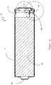
- FIG. 1a and FIG. 1b are a structural schematic view and an exploded perspective view of an electrochemical battery according to the present invention, respectively.
- an electrochemical battery 100 includes a battery case 101, a battery cell 102 disposed within the battery case 101, a negative electrode cap 103, a circuit board module 104 disposed in the space between the battery cell 102 and the negative electrode cap 103, and a positive electrode cap 105.
- the negative electrode cap of the present invention has functions of electromagnetic shielding, electrostatic shielding and heat dissipation.
- the battery cell 102 is housed in the battery case 101.
- the battery case 101 is a steel case with a cylinder or cuboid shaped structure for outputting a positive electrode and fixing the circuit board module 104.
- the positive electrode cap 105 is rotated to the right so as to be integrally formed with the battery case 101.
- the circuit board module 104 is at least one layer of printed circuit boards (PCBs) with a first side and a second side, wherein the first side is directed towards the negative electrode cap 103 relative to the electrochemical battery 100, and the second side is directed towards the battery cell 102 relative to the electrochemical battery 100.
- the PCB is a circuit board having a wiring pattern printed thereon (as shown in FIG. Id) and is of a size substantially corresponding to an inner diameter of the case for the battery 100.
- a plurality of printed wires and components are arranged on the first side or second side of the circuit board module 104.
- the circuit board module 104 is in proximity to the side of the negative electrode cap 103 of the battery 100 and positioned between the battery cell 102 and the negative electrode cap 103.
- a connector is provided on the circuit board module 104 for fixing the negative electrode cap 103 onto the circuit board module 104.
- the negative electrode cap 103 may be fixed onto the circuit board module 104 by means of clamping.
- the circuit board module is configured to perform charging protection and charging indication on the lithium battery as well as discharge protection, short circuit protection, over discharge protection, and output voltage control on the battery.
- Electrode connecting wires 108a and 108b are provided between the circuit module 104 and the battery cell 102 for leading the positive electrode and a negative electrode out of the battery, respectively.
- the connecting wire for the positive electrode is denoted as 108a and the connecting wire for the negative electrode is denoted as 108b.
- FIG. 1c is a sectional view taken along a line A-A in FIG. 1a .
- Insulating washers 106 are provided between the circuit board module 104 and the battery case 101 outside, and between the negative electrode cap 103 and the battery case 101.
- Each of the insulating washers 106 is a flexible and elastic annular insulating padding layer and has a -shaped section along the line A-A of the electrochemical battery 101.
- the insulating washers 106 can play a role of isolating the battery case 101 that serves as a first electrode from the negative electrode cap 103 that serves as a second electrode, and can press and fix the circuit board module 104 due to the elasticity of the insulating padding layer 106 to seal the gap between the battery case 101 and the negative electrode cap 103.
- one segment of the shape is used to press and fix the circuit board module 104 between the loop line 107 and the battery case 101, and the other segment of the shape is used to isolate the battery case 101 from the negative electrode cap 103.
- a loop line 107 is formed as an annular inward recess on an outer surface, corresponding to a location between the battery cell 102 and the printed circuit board 106, of the battery case 101.
- the battery cell 102 is arranged within the battery case 101 and positioned between the positive electrode cap 105 and the loop line 107 structure.
- the insulating washer 106 and the loop line 107 are arranged in such a manner that the circuit board module 104 is fixed between the annular recess of the battery case 101 and the bottom of the battery case 101. Therefore, the battery case 101 and the negative electrode cap 103 are connected without any soldering.
- the loop line 107 structure is configured to position the circuit board module 104.
- the circuit board module 104 is configured with the diameter thereof being sized between an inner diameter of the annular recess constituted by the loop line 107 and an inner diameter of the battery case 101.
- the battery cell 102 has a sealed structure and can be operated by leading a positive electrode and a negative electrode of the battery cell 102 out of the battery cell 102 so as to be connected to the positive electrode and the negative electrode of the battery respectively.
- the loop line 107 has a recess depth of 0.2 mm to 1.2 mm relative to the surface of the battery case 101.
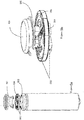
- FIG. 2a shows schematically an exploded perspective structural view showing a sealing body 200 for an electrochemical battery according to a first embodiment of a secondary electrochemical battery of the present invention.
- FIG. 2b shows schematically a partial enlarged sectional view showing a sealing body 200 for an electrochemical battery according to a first embodiment of the present invention.
- the sealing body 200 includes a first PCB 201, a second PCB 202, a negative electrode cap 203, and insulating washers 207 arranged between the second PCB 202 and the battery case 206 and between an exterior portion of the negative electrode cap and the battery case 206.
- the first PCB 201 and the second PCB 202 are two printed circuit boards of the same area.
- the first PCB 201 is close to the battery cell 204, and the second PCB 202 is far away from the battery cell 204.
- the first PCB 201 is engaged onto the battery case 206 through the loop line 205.
- the second PCB 202 and the negative electrode cap 203 are electrically connected through contact and constitute a shielding structure.
- a plurality of chips or circuit components are arranged on one side of the first PCB 201 in proximity to the battery cell 204 and one side of the second PCB 202 far away from the battery cell 204, wherein components generating radiations during operation are arranged in a shielding structure constituted by the second PCB 202 and the negative electrode cap 203.
- the insulating washers 207 are arranged between the second PCB 202 and the battery case 206 and between an exterior portion of the negative electrode cap 203 and the battery case 206.
- Each of the insulating washers 207 is a flexible annular insulating padding layer that can press and fix the first PCB 201 and the second PCB 202 onto the loop line 205 in order to seal the gap between the battery case 206 and the negative electrode cap 203.
- a tin coating 210 for enhancing contact is applied at places where the battery case 206 is in contact with the first PCB and the second PCB, in order to seal the gap between the circuit board and the battery case.
- a negative electrode connecting wire 208b led out of the battery cell 204 is connected with the wires on the first PCB and the second PCB.
- An electrically-conductive material such as a copper coating is coated on the inner surface of the through hole 209 such that the wiring of a plurality of circuit boards can be connected by means of the through hole 209 and connected to a place where the negative electrode cap is in contact with the circuit board, thereby conducting it to the negative electrode cap.
- a large number of electronic components are integrated on the circuit board module of the secondary electrochemical battery according to the present invention, with a relatively integration degree, some electronic components, such as inductive coils, may generate electromagnetic radiation during operation, therefore when the secondary electrochemical battery is used, these electronic components may generate the electromagnetic radiation to affect electronic devices using these batteries.
- some electronic components such as inductive coils
- these electronic components may generate the electromagnetic radiation to affect electronic devices using these batteries.
- the electromagnetic radiation generated by the electronic components of the battery itself may interfere the loudspeaker itself if not shielded, resulting in an undesired squealing noise and affecting the effect of using the electronic devices.
- the sealing body 200 according to the present invention may achieve a purpose of effectively shielding the electromagnetic radiation generated by the electronic components on the PCB by means of the arranged special structure.
- clamp slots are arranged on another side of the PCB board relative to the loop line 205, that is, on one side of the second PCB 202 facing the negative electrode cap 203 as shown in FIG. 2a and 2b , for clamping and fixing the negative electrode cap 203.
- the shape of the clamp slot should correspond to a shape of the edge of the negative electrode cap 203.
- the battery is a cylindrical battery
- the negative electrode cap 203 is of a circular shape
- the clamp slot should be of an annular shape corresponding to the circular shape.
- the clamp slot should be of a rectangular shape corresponding to the rectangular shape.
- One region, surrounded by the clamp slot, of the circuit board module constitutes an enclosed space jointly with the negative electrode cap 203, the electronic component (such as an inductor) generating the electromagnetic radiation is arranged within the enclosed space on one side of the circuit board module facing the negative electrode cap 203, which may effectively shield the electromagnetic radiation generated by the electronic component, and thus may eliminate the electromagnetic interference influences of the electronic devices using the batteries.
- An electrically-conductive material layer such as a metal plating layer, is provided on the inner wall (namely, a contact surface with the negative electrode cap 203) of the clamp slot, for being in conductive contact with the negative electrode cap 203, thereby constituting an enclosed electromagnetic radiation space.
- the negative electrode cap 203 is preferably made of an electrically-conductive material, so as to effectively shield the electromagnetic radiation generated by the electronic components.
- the negative electrode cap 203 is made of a metal.
- sealing body 200 as shown in FIG. 2a and 2b , including two PCBs, is only illustrative, and the sealing body of the present invention is also applicable to one PCB or a combination of multiple layers of PCBs.
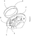
- FIG.3 is an exploded perspective view showing a sealing body 300 for an electrochemical battery according to an embodiment of the present invention.
- the sealing body 300 includes a first PCB 301, a second PCB 302, and a negative electrode cap 303, wherein the first PCB 301 and the second PCB 302 have a plurality of circuit components arranged thereon.
- a plurality of small holes 304 are provided on edges of the first PCB 301 and the second PCB 302 for fixing the first PCB 301 and the second PCB 302 together.
- one side, which is connected to the negative electrode cap 303, of the second PCB 302 has clamp slots 305 (shown in a dashed line in the figure) at locations corresponding to the edge of the negative electrode cap 303, and the edge of the negative electrode cap 303 has clamp protrusions 306 corresponding to the clamp slots 305 for fixing the negative electrode cap 303 onto the second PCB 302 and for realizing electrical connection to form an enclosed electromagnetic shielding space.
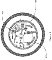
- FIG. 4 shows an electromagnetic shielding structure according to an embodiment of the present invention.
- clamp slots 402 are provided on one side, which is adjacent to the negative electrode cap 303, of the second PCB 302, and FIG. 4 illustrates two opposite clamp slots 402a and 402b.
- a metal ring 401 is arranged on a contact part between the second PCB 302 and the negative electrode cap 303, the clamp slots 402a and 402b are provided within the metal ring 401, and the metal ring 401 is in conductive contact with the clamp slots 402a and 402b, and metal layers, being in conductive contact with the metal ring 401, are provided on the inner walls of the clamp slots 402a and 402b.
- the negative electrode cap 303 After being engaged onto the second PCB 302 through the clamp slots 402, the negative electrode cap 303 is in contact with the metal ring 401 by means of the clamp slots 402, so as to cooperate to function as an electromagnetic shielding shroud.
- the negative electrode cap 303 is made of a metal.
- FIG. 5a is a schematic view showing a shielding structure of a battery sealing body according to an embodiment not forming part of the present invention.
- the negative electrode cap 501 and the battery housing 502 are arranged on two sides of the circuit board 504, and the two both are enclosed metallic cases, the negative electrode cap 501 and the circuit board module 504 constitute a first enclosed electromagnetic shielding space, the battery case 502 and the circuit board module 504 constitute a second enclosed electromagnetic shielding space, and the two enclosed electromagnetic shielding spaces may excellently enclose the electromagnetic interference generated by the circuit on external electric appliances, and excellently shield the damage of external static electricity on the electronic components 503 on an internal circuit of the battery.
- FIG. 5b is an enlarged schematic view showing the shielding structure of the battery sealing body.
- the negative electrode cap 501 is welded on the circuit board 504, and a position of a circuit negative electrode output terminal on the circuit board 504 is a soldering part 506 of the negative electrode cap 501 and the circuit board 504, so that the same wire is used for negative electrode output and circuit grounding, and the induced electricity generated by the high-frequency electronic components 503 goes back to the ground and cannot be transmitted to the outside.
- the soldering part 506 is of a "C"-shaped annular structure.
- a electrochemical battery sealing body has a cleverly and reasonably designed structure in that a sealing region of the electrochemical battery electrode has an electrode cap which can cooperate with a circuit board to form a shielding structure capable of preventing high frequency components inside it from causing interference to an external environment and conducting heat generated by the circuit board during its operation to the external environment, thereby playing a role of protecting the circuit board and the components.
- a loop line structure is arranged on the battery case between the battery cell and the circuit board to position the battery cell and the circuit board relative to each other, and to cooperate with the insulating washer between the electrode cap and the battery case to fix the circuit board without any soldering.
Landscapes
- Chemical & Material Sciences (AREA)
- Chemical Kinetics & Catalysis (AREA)
- Electrochemistry (AREA)
- General Chemical & Material Sciences (AREA)
- Engineering & Computer Science (AREA)
- Microelectronics & Electronic Packaging (AREA)
- Manufacturing & Machinery (AREA)
- Inorganic Chemistry (AREA)
- Sealing Battery Cases Or Jackets (AREA)
- Connection Of Batteries Or Terminals (AREA)
- Battery Mounting, Suspending (AREA)
Description
- The present invention relates to a secondary battery comprising a secondary electrochemical battery sealing body with a packaged chip heat dissipation structure.
- In recent years, secondary batteries (also known as rechargeable batteries) have been widely used in various portable electric devices and electronic devices such as toys and handheld devices. This has imposed an increasingly high requirement on energy storage of the secondary batteries. Lithium-ion secondary batteries have been increasingly applied in such fields due to their advantages such as high energy, capability of high-power discharge, and environmental friendliness.
- During normal operation, the rechargeable batteries often have to cooperate with integrated circuit chips with other functions to achieve desirable operation effects. Usually, the rechargeable batteries are packaged isolately from the integrated circuit chips and then connected with them for use in combination through circuit boards and wires. Such products include a large number of peripheral components, require many manufacture processes, and are high in cost. Also, the rechargeable batteries and the integrated circuit chips are large in volume and relatively poor in performance, which are not beneficial for the miniaturization and microminiaturization.
- In packaging the lithium-ion secondary batteries, each component of the lithium-ion secondary batteries occupies a relatively fixed space. A positive electrode tab, an isolation diaphragm, and a negative electrode tab are arranged inside a polymer battery cell, and one end of the positive electrode tab, facing away from the isolation diaphragm, is packaged by a battery cell top seal of a predefined height. As the battery cell top seal occupies a certain height of the polymer battery cell, the usable space inside the polymer battery cell is reduced. The space utilization of the polymer battery cell is substantially related to the energy density and capacity of the lithium-ion secondary batteries. Generally, the larger the space utilization of the polymer battery cell is, the higher the energy density and capacity of the lithium-ion secondary battery are. Therefore, existing lithium-ion secondary batteries all suffer from the problems of relatively low energy density and capacity due to low space utilization of the polymer battery cell.
- For example, a patent document
US 2011/104538 A1 discloses a cap assembly including a safety vent, a printed circuit board, a thermo device acting as a PTC, a cap-up, and a gasket. And another patent documentEP 1026761 A1 a sealingmember 200 for a secondary battery. The sealing member comprises a metal ring, a flexible substrate carrying an electronic circuit and a terminal cap soldered to the circuit board. The assembly is secured by caulking the peripheral portions of sealing bottom plate and inner gasket. In addition, a patent documentJP 2007 305323 A WO 2015/039584 A1 disclose a rechargeable lithium ion battery comprising a battery sealing body sealing an opening portion of a battery case provided with a loop line, and a battery cell disposed within the battery case. The battery sealing body comprises electrode cap, circuit board and insulating washer. The electrode cap is soldered onto and in electrical contact with the circuit substrate of the printed circuit board, thus forming a fist enclosed electromagnetic shielding space. However, each of the above disclosed documents has some disadvantages. - The present invention, which is defined by the appended claims, provides a secondary electrochemical battery having a sealing body with a packaged chip shielding structure, which is used for sealing an opening portion of a battery case of a secondary electrochemical battery, wherein the sealing body includes a negative electrode cap, a circuit board module and an insulating washer, the battery case has a recessed loop line structure at one end thereof adjacent to the negative electrode cap; the circuit board module is located between a loop line and the negative electrode cap, and a plurality of electronic components for generating electromagnetic radiation during operation are arranged on the circuit board module, the diameter of the circuit board module is sized to be between an inner diameter of a recess composed by the loop line and an inner diameter of the battery case, so that the circuit board module may be clamped in one side of the loop line for sealing the opening portion of the battery case; the circuit board module and the negative electrode cap are connected through an electrically-conductive material, the negative electrode cap and the circuit board module constitute a first enclosed electromagnetic shielding space, the battery case and the circuit board module constitute a second enclosed electromagnetic shielding space, and the electronic components are arranged within the first enclosed electromagnetic shielding space and the second enclosed electromagnetic shielding space; the insulating washer has a ""-shaped section, and disposed within gaps of the battery case, the circuit board module and the negative electrode cap, so as to press and fix the circuit board module between the loop line and the battery case, and isolate the battery case from the negative electrode cap.

- Clamp protrusions corresponding to clamp slots are provided at the edge of the negative electrode cap, for fixing the negative electrode cap on the circuit board module.
- Preferably, the negative electrode cap is made of an electrically-conductive material.
- A metal ring is arranged on a contact part between the circuit board component and the negative electrode cap, the clamp slots are provided within the metal ring, and the metal ring is in conductive contact with the clamp slots, so as to constitute an enclosed electromagnetic shielding space with the negative electrode cap.
- Preferably, the insulating washer is a flexible and elastic annular insulating padding layer. Preferably, one segment of the-shaped insulating washer is used to press and fix the circuit board module between the loop line and the battery case, and the other segment is used to isolate the battery case from the negative electrode cap.
- Preferably, the loop line has a recess depth of 0.2 mm to 1.2 mm relative to the surface of the battery case.
- The sealing body is used to seal an opening portion of a battery case of the secondary electrochemical battery, and the battery further includes a battery cell and a positive electrode cap, the positive electrode cap is connected to the battery case so as to constitute a positive electrode of the secondary battery; the battery cell is disposed within the battery case, and located between the positive electrode cap and the loop line structure.
- A electrochemical battery sealing body according to the present invention has a cleverly and reasonably designed structure in that a sealing region of the electrochemical battery electrode has an electrode cap which can cooperate with a circuit board to form a shielding structure capable of preventing high frequency components inside it from causing interference to an external environment and conducting heat generated by the circuit board during its operation to the external environment, thereby playing a role of protecting the circuit board and the components. Further, a loop line structure is arranged on the battery case between the battery cell and the circuit board to position the battery cell and the circuit board relative to each other, and to cooperate with the insulating washer between the electrode cap and the battery case to fix the circuit board without any soldering.
- Further objects, functions, and advantages of the present invention shall become apparent from the following description of embodiments of the present invention with reference to accompanying drawings, wherein
-
FIG. 1a schematically shows a structural schematic view showing an electrochemical battery according to the present invention. -
FIG. 1b is an exploded perspective view showing an electrochemical battery according to the present invention. -
FIG. 1c is a cross-sectional view ofFIG. 1a taken along a line A-A. - FIG. Id is a circuit schematic view showing a circuit board module according to the present invention.
-
FIG. 2a schematically shows an exploded perspective structural schematic view showing an electrochemicalbattery sealing body 200 for the secondary electrochemical battery. -
FIG. 2b schematically shows an enlarged partial cross-sectional view showing an electrochemicalbattery sealing body 200. -
FIG. 3 is an exploded perspective view showing a sealing body 300 for an electrochemical battery according to an embodiment of the present invention. -
FIG. 4 is a structural schematic view showing another embodiment of a second printed circuit board according to an embodiment of the present invention. -
FIG. 5a is a structural schematic view showing a shielding structure according to an embodiment not forming part of the present invention. -
FIG. 5b is an enlarged partial structural schematic view ofFIG. 5a . - With reference to exemplary embodiments, objects and functions of the present invention as well as methods for achieving them shall be explained. However, the present invention is not to be limited by the exemplary embodiments disclosed below, but can be realized in various forms. The specification is intended in nature solely to provide a thorough understanding of specific details of the present invention to those skilled in the art.
- It should be understood that the general description above and detailed description below are only exemplarily explanative and illustrative, and shall not be understood as limitations on the protection scope claimed by the present invention.
- In the following, embodiments of the present invention will be described with reference to the accompanying drawings. In the accompanying drawings, like reference numerals refer to like or similar parts, or like or similar steps.
- The present invention provides a secondary electrochemical battery.
FIG. 1a and FIG. 1b are a structural schematic view and an exploded perspective view of an electrochemical battery according to the present invention, respectively. As shown inFIG. 1a and FIG. 1b , anelectrochemical battery 100 includes abattery case 101, abattery cell 102 disposed within thebattery case 101, anegative electrode cap 103, acircuit board module 104 disposed in the space between thebattery cell 102 and thenegative electrode cap 103, and apositive electrode cap 105. The negative electrode cap of the present invention has functions of electromagnetic shielding, electrostatic shielding and heat dissipation. Thebattery cell 102 is housed in thebattery case 101. Thebattery case 101 is a steel case with a cylinder or cuboid shaped structure for outputting a positive electrode and fixing thecircuit board module 104. According to one embodiment of the present invention, thepositive electrode cap 105 is rotated to the right so as to be integrally formed with thebattery case 101. - The
circuit board module 104 is at least one layer of printed circuit boards (PCBs) with a first side and a second side, wherein the first side is directed towards thenegative electrode cap 103 relative to theelectrochemical battery 100, and the second side is directed towards thebattery cell 102 relative to theelectrochemical battery 100. The PCB is a circuit board having a wiring pattern printed thereon (as shown in FIG. Id) and is of a size substantially corresponding to an inner diameter of the case for thebattery 100. A plurality of printed wires and components are arranged on the first side or second side of thecircuit board module 104. Thecircuit board module 104 is in proximity to the side of thenegative electrode cap 103 of thebattery 100 and positioned between thebattery cell 102 and thenegative electrode cap 103. A connector is provided on thecircuit board module 104 for fixing thenegative electrode cap 103 onto thecircuit board module 104. For example, thenegative electrode cap 103 may be fixed onto thecircuit board module 104 by means of clamping. The circuit board module is configured to perform charging protection and charging indication on the lithium battery as well as discharge protection, short circuit protection, over discharge protection, and output voltage control on the battery.Electrode connecting wires circuit module 104 and thebattery cell 102 for leading the positive electrode and a negative electrode out of the battery, respectively. The connecting wire for the positive electrode is denoted as 108a and the connecting wire for the negative electrode is denoted as 108b.FIG. 1c is a sectional view taken along a line A-A inFIG. 1a . Insulatingwashers 106 are provided between thecircuit board module 104 and thebattery case 101 outside, and between thenegative electrode cap 103 and thebattery case 101. Each of the insulatingwashers 106 is a flexible and elastic annular insulating padding layer and has a-shaped section along the line A-A of theelectrochemical battery 101. The insulatingwashers 106 can play a role of isolating thebattery case 101 that serves as a first electrode from thenegative electrode cap 103 that serves as a second electrode, and can press and fix thecircuit board module 104 due to the elasticity of the insulatingpadding layer 106 to seal the gap between thebattery case 101 and thenegative electrode cap 103. Particularly, as shown inFIG. 1c , one segment of theshape is used to press and fix thecircuit board module 104 between theloop line 107 and thebattery case 101, and the other segment of theshape is used to isolate thebattery case 101 from thenegative electrode cap 103. - A
loop line 107 is formed as an annular inward recess on an outer surface, corresponding to a location between thebattery cell 102 and the printedcircuit board 106, of thebattery case 101. Thebattery cell 102 is arranged within thebattery case 101 and positioned between thepositive electrode cap 105 and theloop line 107 structure. The insulatingwasher 106 and theloop line 107 are arranged in such a manner that thecircuit board module 104 is fixed between the annular recess of thebattery case 101 and the bottom of thebattery case 101. Therefore, thebattery case 101 and thenegative electrode cap 103 are connected without any soldering. - The
loop line 107 structure is configured to position thecircuit board module 104. Particularly, thecircuit board module 104 is configured with the diameter thereof being sized between an inner diameter of the annular recess constituted by theloop line 107 and an inner diameter of thebattery case 101. When the battery is assembled, thebattery cell 102 is arranged in thebattery case 101; then thecircuit board module 104 is assembled into thebattery case 101, thecircuit board module 104 is sized so that it can be engaged onto theloop line 107 structure, thereby avoiding being in contact with thebattery cell 102; and then thebattery case 101 is isolated from thenegative electrode cap 103 through the insulatingpadding layer 106. As such, the assembly of thebattery 100 is completed. Such a structure allows thecircuit board module 104 to form an enclosed space inside thebattery case 101 for accommodating thebattery cell 102 by means of theloop line 107 structure, therefore the volume of thebattery cell 102 and thus the capacity of the secondary battery can be increased. Preferably, thebattery cell 102 has a sealed structure and can be operated by leading a positive electrode and a negative electrode of thebattery cell 102 out of thebattery cell 102 so as to be connected to the positive electrode and the negative electrode of the battery respectively. - Preferably, the
loop line 107 has a recess depth of 0.2 mm to 1.2 mm relative to the surface of thebattery case 101. -
FIG. 2a shows schematically an exploded perspective structural view showing a sealingbody 200 for an electrochemical battery according to a first embodiment of a secondary electrochemical battery of the present invention.FIG. 2b shows schematically a partial enlarged sectional view showing a sealingbody 200 for an electrochemical battery according to a first embodiment of the present invention. As shown inFIG. 2a and FIG. 2b , the sealingbody 200 includes afirst PCB 201, asecond PCB 202, anegative electrode cap 203, and insulatingwashers 207 arranged between thesecond PCB 202 and thebattery case 206 and between an exterior portion of the negative electrode cap and thebattery case 206. According to one embodiment of the present invention, thefirst PCB 201 and thesecond PCB 202 are two printed circuit boards of the same area. Thefirst PCB 201 is close to thebattery cell 204, and thesecond PCB 202 is far away from thebattery cell 204. Thefirst PCB 201 is engaged onto thebattery case 206 through theloop line 205. Thesecond PCB 202 and thenegative electrode cap 203 are electrically connected through contact and constitute a shielding structure. A plurality of chips or circuit components are arranged on one side of thefirst PCB 201 in proximity to thebattery cell 204 and one side of thesecond PCB 202 far away from thebattery cell 204, wherein components generating radiations during operation are arranged in a shielding structure constituted by thesecond PCB 202 and thenegative electrode cap 203. The insulatingwashers 207 are arranged between thesecond PCB 202 and thebattery case 206 and between an exterior portion of thenegative electrode cap 203 and thebattery case 206. Each of the insulatingwashers 207 is a flexible annular insulating padding layer that can press and fix thefirst PCB 201 and thesecond PCB 202 onto theloop line 205 in order to seal the gap between thebattery case 206 and thenegative electrode cap 203. Atin coating 210 for enhancing contact is applied at places where thebattery case 206 is in contact with the first PCB and the second PCB, in order to seal the gap between the circuit board and the battery case. By means of a through hole 209 between the first PCB and the second PCB, a negativeelectrode connecting wire 208b (and a positive electrode connecting wire denoted as 208a, which is not shown in the figure) led out of thebattery cell 204 is connected with the wires on the first PCB and the second PCB. An electrically-conductive material such as a copper coating is coated on the inner surface of the through hole 209 such that the wiring of a plurality of circuit boards can be connected by means of the through hole 209 and connected to a place where the negative electrode cap is in contact with the circuit board, thereby conducting it to the negative electrode cap. - A large number of electronic components are integrated on the circuit board module of the secondary electrochemical battery according to the present invention, with a relatively integration degree, some electronic components, such as inductive coils, may generate electromagnetic radiation during operation, therefore when the secondary electrochemical battery is used, these electronic components may generate the electromagnetic radiation to affect electronic devices using these batteries. For example, when a battery is used on the electronic devices, such as a loudspeaker, the electromagnetic radiation generated by the electronic components of the battery itself may interfere the loudspeaker itself if not shielded, resulting in an undesired squealing noise and affecting the effect of using the electronic devices. The sealing
body 200 according to the present invention may achieve a purpose of effectively shielding the electromagnetic radiation generated by the electronic components on the PCB by means of the arranged special structure. - In particular, according to one embodiment of the present invention, clamp slots are arranged on another side of the PCB board relative to the
loop line 205, that is, on one side of thesecond PCB 202 facing thenegative electrode cap 203 as shown inFIG. 2a and 2b , for clamping and fixing thenegative electrode cap 203. In order to achieve good electromagnetic radiation shielding, the shape of the clamp slot should correspond to a shape of the edge of thenegative electrode cap 203. For example, if the battery is a cylindrical battery, thenegative electrode cap 203 is of a circular shape, then the clamp slot should be of an annular shape corresponding to the circular shape. If thenegative electrode cap 203 is of a rectangular shape, then the clamp slot should be of a rectangular shape corresponding to the rectangular shape. One region, surrounded by the clamp slot, of the circuit board module constitutes an enclosed space jointly with thenegative electrode cap 203, the electronic component (such as an inductor) generating the electromagnetic radiation is arranged within the enclosed space on one side of the circuit board module facing thenegative electrode cap 203, which may effectively shield the electromagnetic radiation generated by the electronic component, and thus may eliminate the electromagnetic interference influences of the electronic devices using the batteries. An electrically-conductive material layer, such as a metal plating layer, is provided on the inner wall (namely, a contact surface with the negative electrode cap 203) of the clamp slot, for being in conductive contact with thenegative electrode cap 203, thereby constituting an enclosed electromagnetic radiation space. - The
negative electrode cap 203 is preferably made of an electrically-conductive material, so as to effectively shield the electromagnetic radiation generated by the electronic components. For example, thenegative electrode cap 203 is made of a metal. - It is to be understood by those skilled in the art that the sealing
body 200, as shown inFIG. 2a and 2b , including two PCBs, is only illustrative, and the sealing body of the present invention is also applicable to one PCB or a combination of multiple layers of PCBs. -
FIG.3 is an exploded perspective view showing a sealing body 300 for an electrochemical battery according to an embodiment of the present invention. The sealing body 300 includes afirst PCB 301, asecond PCB 302, and anegative electrode cap 303, wherein thefirst PCB 301 and thesecond PCB 302 have a plurality of circuit components arranged thereon. A plurality ofsmall holes 304 are provided on edges of thefirst PCB 301 and thesecond PCB 302 for fixing thefirst PCB 301 and thesecond PCB 302 together. According to one embodiment of the present invention, one side, which is connected to thenegative electrode cap 303, of thesecond PCB 302 has clamp slots 305 (shown in a dashed line in the figure) at locations corresponding to the edge of thenegative electrode cap 303, and the edge of thenegative electrode cap 303 hasclamp protrusions 306 corresponding to theclamp slots 305 for fixing thenegative electrode cap 303 onto thesecond PCB 302 and for realizing electrical connection to form an enclosed electromagnetic shielding space. -
FIG. 4 shows an electromagnetic shielding structure according to an embodiment of the present invention. As shown inFIG. 4 , clamp slots 402 are provided on one side, which is adjacent to thenegative electrode cap 303, of thesecond PCB 302, andFIG. 4 illustrates twoopposite clamp slots metal ring 401 is arranged on a contact part between thesecond PCB 302 and thenegative electrode cap 303, theclamp slots metal ring 401, and themetal ring 401 is in conductive contact with theclamp slots metal ring 401, are provided on the inner walls of theclamp slots second PCB 302 through the clamp slots 402, thenegative electrode cap 303 is in contact with themetal ring 401 by means of the clamp slots 402, so as to cooperate to function as an electromagnetic shielding shroud. Thenegative electrode cap 303 is made of a metal. -
FIG. 5a is a schematic view showing a shielding structure of a battery sealing body according to an embodiment not forming part of the present invention. As shown inFIG. 5a , thenegative electrode cap 501 and thebattery housing 502 are arranged on two sides of thecircuit board 504, and the two both are enclosed metallic cases, thenegative electrode cap 501 and thecircuit board module 504 constitute a first enclosed electromagnetic shielding space, thebattery case 502 and thecircuit board module 504 constitute a second enclosed electromagnetic shielding space, and the two enclosed electromagnetic shielding spaces may excellently enclose the electromagnetic interference generated by the circuit on external electric appliances, and excellently shield the damage of external static electricity on theelectronic components 503 on an internal circuit of the battery.FIG. 5b is an enlarged schematic view showing the shielding structure of the battery sealing body. As shown inFIG. 5b , thenegative electrode cap 501 is welded on thecircuit board 504, and a position of a circuit negative electrode output terminal on thecircuit board 504 is asoldering part 506 of thenegative electrode cap 501 and thecircuit board 504, so that the same wire is used for negative electrode output and circuit grounding, and the induced electricity generated by the high-frequencyelectronic components 503 goes back to the ground and cannot be transmitted to the outside. Preferably, thesoldering part 506 is of a "C"-shaped annular structure. - A electrochemical battery sealing body according to the present invention has a cleverly and reasonably designed structure in that a sealing region of the electrochemical battery electrode has an electrode cap which can cooperate with a circuit board to form a shielding structure capable of preventing high frequency components inside it from causing interference to an external environment and conducting heat generated by the circuit board during its operation to the external environment, thereby playing a role of protecting the circuit board and the components. Further, a loop line structure is arranged on the battery case between the battery cell and the circuit board to position the battery cell and the circuit board relative to each other, and to cooperate with the insulating washer between the electrode cap and the battery case to fix the circuit board without any soldering.
- Other embodiments of the present invention can readily occur to and be understood by those skilled in the art in light of the description and practice of the present invention disclosed herein. Such description and embodiments are solely meant to be illustrative and the true scope of the present invention is defined by the claims.
Claims (4)
- A secondary electrochemical battery (100, 200), comprising
a battery case (101, 206) with a recessed loop line structure (107, 205) at one end thereof adjacent to a negative electrode cap (103, 203, 303),
a positive electrode cap (105) connected to the battery case (101, 206) so as to constitute a positive electrode of the secondary battery (100),
a battery cell (102, 204) disposed within the battery case (101, 206) and located between the positive electrode cap (105) and the recessed loop line structure (107, 205),
a secondary electrochemical battery sealing body (200, 300, 400) with a packaged chip shielding structure, which is used for sealing an opening portion of the battery case (101, 206),
wherein the sealing body (200, 300, 400) comprises the negative electrode cap (103, 203, 303), a circuit board module (104, 201, 202, 301, 302) and an insulating washer (106, 207),
the circuit board module (104, 201, 202, 301, 302) is located between the recessed loop line structure (107, 205) and the negative electrode cap (103, 203, 303), and a plurality of electronic components for generating electromagnetic radiation during operation are arranged on the circuit board module (104, 201, 202, 301, 302), the diameter of the circuit board module is sized to be between an inner diameter of a recess composed by the recessed loop line structure (107, 205) and an inner diameter of the battery case, so that the circuit board module may be clamped in one side of the recessed loop line structure (107, 205) for sealing the opening portion of the battery case (101, 206); the circuit board module (104, 201, 202, 301, 302) and the negative electrode cap (103, 203, 303) are connected through an electrically-conductive material, the negative electrode cap (103, 203, 303) and the circuit board module (104, 201, 202, 301, 302) constitute a first enclosed electromagnetic shielding space, the battery case (101, 206) and the circuit board module (104, 201, 202, 301, 302) constitute a second enclosed electromagnetic shielding space, and the electronic components are arranged within the first enclosed electromagnetic shielding space and the second enclosed electromagnetic shielding space;
a metal ring (401) is arranged on a contact part between the circuit board module (104, 201, 202, 301, 302) and the negative electrode cap (103, 203, 303), clamp slots (305, 402) are provided within the metal ring (401), and the metal ring is in conductive contact with the clamp slots, so as to constitute an enclosed electromagnetic shielding space with the negative electrode cap; and
the insulating washer (106, 207) has a ""-shaped section, and is disposed within gaps among the battery case, the circuit board module and the negative electrode cap, so as to press and fix the circuit board module between the recessed loop line structure (107, 205) and the battery case (101, 206), and isolate the battery case from the negative electrode cap,
wherein clamp protrusions (306) corresponding to the clamp slots (305, 402) are provided at the edge of the negative electrode cap, for fixing the negative electrode cap on the circuit board module. - The secondary electrochemical battery (100, 200) according to claim 1, wherein the negative electrode cap (103, 203, 303) is made of an electrically-conductive material.
- The secondary electrochemical battery (100, 200) according to claim 1, wherein the insulating washer (106, 207) is a flexible and elastic annular insulating padding layer.
- The secondary electrochemical battery (100, 200) according to claim 1, wherein one segment of the-shaped insulating washer (106, 207) is used to press and fix the circuit board module between the recessed loop line structure (107, 205) and the battery case (101, 206), and the other segment is used to isolate the battery case from the negative electrode cap.
Applications Claiming Priority (3)
| Application Number | Priority Date | Filing Date | Title |
|---|---|---|---|
| CN201520404078.XU CN204927362U (en) | 2015-06-12 | 2015-06-12 | Secondary electrochemical battery sealing body and battery with packaged chip shielding structure |
| CN201510321435.0A CN104900820B (en) | 2015-06-12 | 2015-06-12 | Secondary electrochemical battery sealing body with encapsulated type chip shield structure and battery |
| PCT/CN2015/096611 WO2016197566A1 (en) | 2015-06-12 | 2015-12-08 | Secondary electrochemical battery sealer body having packaged chip shielding structure and battery |
Publications (3)
| Publication Number | Publication Date |
|---|---|
| EP3297056A1 EP3297056A1 (en) | 2018-03-21 |
| EP3297056A4 EP3297056A4 (en) | 2018-04-04 |
| EP3297056B1 true EP3297056B1 (en) | 2020-04-22 |
Family
ID=57502833
Family Applications (1)
| Application Number | Title | Priority Date | Filing Date |
|---|---|---|---|
| EP15894821.6A Active EP3297056B1 (en) | 2015-06-12 | 2015-12-08 | Secondary electrochemical battery with sealer body and packaged chip shielding structure |
Country Status (5)
| Country | Link |
|---|---|
| US (1) | US10026997B2 (en) |
| EP (1) | EP3297056B1 (en) |
| JP (1) | JP6564072B2 (en) |
| ES (1) | ES2807253T3 (en) |
| WO (1) | WO2016197566A1 (en) |
Families Citing this family (11)
| Publication number | Priority date | Publication date | Assignee | Title |
|---|---|---|---|---|
| JP6931347B2 (en) | 2015-09-08 | 2021-09-08 | ボルト テクノロジー リミテッド | Battery with voltage regulator |
| CN110546847B (en) | 2017-03-07 | 2024-08-13 | 伏特技术有限公司 | Battery with voltage regulator |
| JP6787263B2 (en) | 2017-07-10 | 2020-11-18 | トヨタ自動車株式会社 | Power supply |
| JP7334790B2 (en) * | 2019-10-08 | 2023-08-29 | 株式会社村田製作所 | Battery packs and electronic devices |
| CN112839455B (en) * | 2019-11-22 | 2022-10-28 | 新电元工业株式会社 | Electronic device with a detachable cover |
| CN120015976A (en) * | 2020-01-17 | 2025-05-16 | 广东美尼麦格松电源系统有限公司 | Cylindrical secondary battery |
| CN111769337B (en) * | 2020-01-17 | 2024-09-13 | 广东美尼麦格松电源系统有限公司 | Columnar battery and controller with indicator light |
| CN114335809B (en) * | 2022-01-25 | 2024-03-08 | 深圳市东方芯愿新能源有限公司 | Double-layer circuit board lithium battery device |
| CN217507588U (en) * | 2022-04-29 | 2022-09-27 | 澎湃云科技(深圳)有限公司 | Terminal is arranged to positive negative pole homopolar |
| KR20240047837A (en) * | 2022-10-05 | 2024-04-12 | 주식회사 엘지에너지솔루션 | Cylindrical battery cell |
| US12331910B2 (en) * | 2023-04-13 | 2025-06-17 | Rongchang Cao | Light-emitting device inside toy |
Citations (1)
| Publication number | Priority date | Publication date | Assignee | Title |
|---|---|---|---|---|
| WO2015039584A1 (en) * | 2013-09-23 | 2015-03-26 | 李松 | Universal rechargeable battery constituted by employing lithium-ion battery and control method |
Family Cites Families (14)
| Publication number | Priority date | Publication date | Assignee | Title |
|---|---|---|---|---|
| US6524739B1 (en) * | 1998-08-25 | 2003-02-25 | Matsushita Electric Industrial Co., Ltd. | Secondary battery |
| JP3220681B2 (en) * | 1999-03-30 | 2001-10-22 | 松下電器産業株式会社 | Battery with battery protection device |
| KR100624934B1 (en) * | 2004-10-28 | 2006-09-15 | 삼성에스디아이 주식회사 | Cylindrical lithium secondary battery |
| JP5055824B2 (en) * | 2006-05-09 | 2012-10-24 | ソニー株式会社 | battery |
| KR100938104B1 (en) * | 2007-10-30 | 2010-01-21 | 삼성에스디아이 주식회사 | Method for manufacturing can type secondary battery and circuit board for secondary battery |
| KR20100063378A (en) * | 2008-12-03 | 2010-06-11 | 삼성에스디아이 주식회사 | Battery pack |
| US8481183B2 (en) * | 2008-12-23 | 2013-07-09 | Samsung Sdi Co., Ltd. | Secondary battery |
| KR101084209B1 (en) * | 2009-10-29 | 2011-11-17 | 삼성에스디아이 주식회사 | Cylindrical rechargeable battery with improved cap up structure |
| CN102738480B (en) * | 2011-04-14 | 2014-06-18 | 广州市虎头电池集团有限公司 | Light-emitting cell |
| CN103208594B (en) * | 2012-12-04 | 2016-04-27 | 丁振荣 | Cylindrical battery cell, battery and housing cap sealed fixing means |
| JP6533310B2 (en) * | 2015-06-12 | 2019-06-19 | 福建南平南孚電池有限公司 | Secondary electrochemical cell sealing body with charge indication lamp |
| CN204927362U (en) * | 2015-06-12 | 2015-12-30 | 福建南平南孚电池有限公司 | Secondary electrochemical battery sealing body and battery with packaged chip shielding structure |
| CN104900820B (en) * | 2015-06-12 | 2017-03-22 | 福建南平南孚电池有限公司 | Secondary electrochemical battery sealing body with encapsulated type chip shield structure and battery |
| EP3291328B1 (en) * | 2015-06-12 | 2019-05-22 | Fujian Nanping Nanfu Battery Co., Ltd. | Electrochemical secondary battery having inbuilt charging circuit |
-
2015
- 2015-12-08 WO PCT/CN2015/096611 patent/WO2016197566A1/en not_active Ceased
- 2015-12-08 JP JP2017562344A patent/JP6564072B2/en active Active
- 2015-12-08 EP EP15894821.6A patent/EP3297056B1/en active Active
- 2015-12-08 ES ES15894821T patent/ES2807253T3/en active Active
-
2017
- 2017-08-09 US US15/672,733 patent/US10026997B2/en active Active
Patent Citations (2)
| Publication number | Priority date | Publication date | Assignee | Title |
|---|---|---|---|---|
| WO2015039584A1 (en) * | 2013-09-23 | 2015-03-26 | 李松 | Universal rechargeable battery constituted by employing lithium-ion battery and control method |
| EP3051622A1 (en) * | 2013-09-23 | 2016-08-03 | Shenzhen Maigesong Electrical Co., Ltd. | Universal rechargeable battery constituted by employing lithium-ion battery and control method |
Also Published As
| Publication number | Publication date |
|---|---|
| US10026997B2 (en) | 2018-07-17 |
| JP6564072B2 (en) | 2019-08-21 |
| ES2807253T3 (en) | 2021-02-22 |
| WO2016197566A1 (en) | 2016-12-15 |
| JP2018521460A (en) | 2018-08-02 |
| EP3297056A1 (en) | 2018-03-21 |
| EP3297056A4 (en) | 2018-04-04 |
| US20170338521A1 (en) | 2017-11-23 |
Similar Documents
| Publication | Publication Date | Title |
|---|---|---|
| EP3297056A1 (en) | Secondary electrochemical battery sealer body having packaged chip shielding structure and battery | |
| US10224582B2 (en) | Electrochemical secondary battery having inbuilt charging circuit | |
| KR101658821B1 (en) | Shield can of mobile terminal | |
| US8750551B2 (en) | Shielded microphone for mobile communications device | |
| US20090268420A1 (en) | Shielding assembly | |
| US9941494B2 (en) | Battery pack | |
| KR101430618B1 (en) | Battery Pack and electronic device including the same | |
| WO2016197567A1 (en) | Secondary electrochemical battery sealer body having packaged chip heat dissipation structure and battery | |
| WO2016197563A1 (en) | Negative electrode sealing body of secondary battery | |
| EP1633015B1 (en) | Sealing member and sealing structure of electronic circuit unit | |
| CN112187970A (en) | Camera module and electronic device thereof | |
| CN104900820A (en) | Secondary electrochemical battery sealing body with encapsulated type chip shield structure and battery | |
| CN204668364U (en) | A kind of electrochemical secondary cell being built in charging circuit | |
| WO2005088747A1 (en) | Portable communication equipment and battery pack | |
| EP3291335B1 (en) | Secondary electrochemical battery sealing body with charge indicating lamp | |
| JP2015176973A (en) | Microwave circuit module | |
| CN213213082U (en) | Residual current protector with electromagnetic shielding structure | |
| CN204927362U (en) | Secondary electrochemical battery sealing body and battery with packaged chip shielding structure | |
| KR101531098B1 (en) | Communication package module | |
| KR20180118433A (en) | Receptacle connector | |
| WO2016197564A1 (en) | Seal ring for secondary battery cathode sealing body | |
| EP1843625B1 (en) | Shielded Microphone for Mobile Communications Device | |
| CN222395984U (en) | EMC shielding cover and electronic equipment | |
| CN219717426U (en) | Connector and connecting assembly thereof | |
| KR101551145B1 (en) | Communication package module |
Legal Events
| Date | Code | Title | Description |
|---|---|---|---|
| STAA | Information on the status of an ep patent application or granted ep patent |
Free format text: STATUS: THE INTERNATIONAL PUBLICATION HAS BEEN MADE |
|
| PUAI | Public reference made under article 153(3) epc to a published international application that has entered the european phase |
Free format text: ORIGINAL CODE: 0009012 |
|
| STAA | Information on the status of an ep patent application or granted ep patent |
Free format text: STATUS: REQUEST FOR EXAMINATION WAS MADE |
|
| 17P | Request for examination filed |
Effective date: 20171130 |
|
| AK | Designated contracting states |
Kind code of ref document: A1 Designated state(s): AL AT BE BG CH CY CZ DE DK EE ES FI FR GB GR HR HU IE IS IT LI LT LU LV MC MK MT NL NO PL PT RO RS SE SI SK SM TR |
|
| AX | Request for extension of the european patent |
Extension state: BA ME |
|
| A4 | Supplementary search report drawn up and despatched |
Effective date: 20180301 |
|
| RIC1 | Information provided on ipc code assigned before grant |
Ipc: H01M 2/04 20060101AFI20180223BHEP Ipc: H01M 10/42 20060101ALI20180223BHEP Ipc: H01M 2/08 20060101ALI20180223BHEP Ipc: H01M 10/613 20140101ALI20180223BHEP Ipc: H05K 9/00 20060101ALI20180223BHEP |
|
| STAA | Information on the status of an ep patent application or granted ep patent |
Free format text: STATUS: EXAMINATION IS IN PROGRESS |
|
| 17Q | First examination report despatched |
Effective date: 20180626 |
|
| DAV | Request for validation of the european patent (deleted) | ||
| DAX | Request for extension of the european patent (deleted) | ||
| GRAP | Despatch of communication of intention to grant a patent |
Free format text: ORIGINAL CODE: EPIDOSNIGR1 |
|
| STAA | Information on the status of an ep patent application or granted ep patent |
Free format text: STATUS: GRANT OF PATENT IS INTENDED |
|
| INTG | Intention to grant announced |
Effective date: 20191121 |
|
| GRAS | Grant fee paid |
Free format text: ORIGINAL CODE: EPIDOSNIGR3 |
|
| GRAA | (expected) grant |
Free format text: ORIGINAL CODE: 0009210 |
|
| STAA | Information on the status of an ep patent application or granted ep patent |
Free format text: STATUS: THE PATENT HAS BEEN GRANTED |
|
| AK | Designated contracting states |
Kind code of ref document: B1 Designated state(s): AL AT BE BG CH CY CZ DE DK EE ES FI FR GB GR HR HU IE IS IT LI LT LU LV MC MK MT NL NO PL PT RO RS SE SI SK SM TR |
|
| REG | Reference to a national code |
Ref country code: CH Ref legal event code: EP |
|
| REG | Reference to a national code |
Ref country code: IE Ref legal event code: FG4D |
|
| REG | Reference to a national code |
Ref country code: DE Ref legal event code: R096 Ref document number: 602015051426 Country of ref document: DE |
|
| REG | Reference to a national code |
Ref country code: AT Ref legal event code: REF Ref document number: 1261321 Country of ref document: AT Kind code of ref document: T Effective date: 20200515 |
|
| REG | Reference to a national code |
Ref country code: LT Ref legal event code: MG4D |
|
| REG | Reference to a national code |
Ref country code: NL Ref legal event code: MP Effective date: 20200422 |
|
| PG25 | Lapsed in a contracting state [announced via postgrant information from national office to epo] |
Ref country code: GR Free format text: LAPSE BECAUSE OF FAILURE TO SUBMIT A TRANSLATION OF THE DESCRIPTION OR TO PAY THE FEE WITHIN THE PRESCRIBED TIME-LIMIT Effective date: 20200723 Ref country code: NO Free format text: LAPSE BECAUSE OF FAILURE TO SUBMIT A TRANSLATION OF THE DESCRIPTION OR TO PAY THE FEE WITHIN THE PRESCRIBED TIME-LIMIT Effective date: 20200722 Ref country code: PT Free format text: LAPSE BECAUSE OF FAILURE TO SUBMIT A TRANSLATION OF THE DESCRIPTION OR TO PAY THE FEE WITHIN THE PRESCRIBED TIME-LIMIT Effective date: 20200824 Ref country code: SE Free format text: LAPSE BECAUSE OF FAILURE TO SUBMIT A TRANSLATION OF THE DESCRIPTION OR TO PAY THE FEE WITHIN THE PRESCRIBED TIME-LIMIT Effective date: 20200422 Ref country code: NL Free format text: LAPSE BECAUSE OF FAILURE TO SUBMIT A TRANSLATION OF THE DESCRIPTION OR TO PAY THE FEE WITHIN THE PRESCRIBED TIME-LIMIT Effective date: 20200422 Ref country code: LT Free format text: LAPSE BECAUSE OF FAILURE TO SUBMIT A TRANSLATION OF THE DESCRIPTION OR TO PAY THE FEE WITHIN THE PRESCRIBED TIME-LIMIT Effective date: 20200422 Ref country code: FI Free format text: LAPSE BECAUSE OF FAILURE TO SUBMIT A TRANSLATION OF THE DESCRIPTION OR TO PAY THE FEE WITHIN THE PRESCRIBED TIME-LIMIT Effective date: 20200422 Ref country code: IS Free format text: LAPSE BECAUSE OF FAILURE TO SUBMIT A TRANSLATION OF THE DESCRIPTION OR TO PAY THE FEE WITHIN THE PRESCRIBED TIME-LIMIT Effective date: 20200822 |
|
| REG | Reference to a national code |
Ref country code: AT Ref legal event code: MK05 Ref document number: 1261321 Country of ref document: AT Kind code of ref document: T Effective date: 20200422 |
|
| REG | Reference to a national code |
Ref country code: DE Ref legal event code: R079 Ref document number: 602015051426 Country of ref document: DE Free format text: PREVIOUS MAIN CLASS: H01M0002040000 Ipc: H01M0050147000 |
|
| PG25 | Lapsed in a contracting state [announced via postgrant information from national office to epo] |
Ref country code: HR Free format text: LAPSE BECAUSE OF FAILURE TO SUBMIT A TRANSLATION OF THE DESCRIPTION OR TO PAY THE FEE WITHIN THE PRESCRIBED TIME-LIMIT Effective date: 20200422 Ref country code: LV Free format text: LAPSE BECAUSE OF FAILURE TO SUBMIT A TRANSLATION OF THE DESCRIPTION OR TO PAY THE FEE WITHIN THE PRESCRIBED TIME-LIMIT Effective date: 20200422 Ref country code: RS Free format text: LAPSE BECAUSE OF FAILURE TO SUBMIT A TRANSLATION OF THE DESCRIPTION OR TO PAY THE FEE WITHIN THE PRESCRIBED TIME-LIMIT Effective date: 20200422 Ref country code: BG Free format text: LAPSE BECAUSE OF FAILURE TO SUBMIT A TRANSLATION OF THE DESCRIPTION OR TO PAY THE FEE WITHIN THE PRESCRIBED TIME-LIMIT Effective date: 20200722 |
|
| PG25 | Lapsed in a contracting state [announced via postgrant information from national office to epo] |
Ref country code: AL Free format text: LAPSE BECAUSE OF FAILURE TO SUBMIT A TRANSLATION OF THE DESCRIPTION OR TO PAY THE FEE WITHIN THE PRESCRIBED TIME-LIMIT Effective date: 20200422 |
|
| REG | Reference to a national code |
Ref country code: DE Ref legal event code: R097 Ref document number: 602015051426 Country of ref document: DE |
|
| PG25 | Lapsed in a contracting state [announced via postgrant information from national office to epo] |
Ref country code: CZ Free format text: LAPSE BECAUSE OF FAILURE TO SUBMIT A TRANSLATION OF THE DESCRIPTION OR TO PAY THE FEE WITHIN THE PRESCRIBED TIME-LIMIT Effective date: 20200422 Ref country code: RO Free format text: LAPSE BECAUSE OF FAILURE TO SUBMIT A TRANSLATION OF THE DESCRIPTION OR TO PAY THE FEE WITHIN THE PRESCRIBED TIME-LIMIT Effective date: 20200422 Ref country code: EE Free format text: LAPSE BECAUSE OF FAILURE TO SUBMIT A TRANSLATION OF THE DESCRIPTION OR TO PAY THE FEE WITHIN THE PRESCRIBED TIME-LIMIT Effective date: 20200422 Ref country code: AT Free format text: LAPSE BECAUSE OF FAILURE TO SUBMIT A TRANSLATION OF THE DESCRIPTION OR TO PAY THE FEE WITHIN THE PRESCRIBED TIME-LIMIT Effective date: 20200422 Ref country code: SM Free format text: LAPSE BECAUSE OF FAILURE TO SUBMIT A TRANSLATION OF THE DESCRIPTION OR TO PAY THE FEE WITHIN THE PRESCRIBED TIME-LIMIT Effective date: 20200422 Ref country code: DK Free format text: LAPSE BECAUSE OF FAILURE TO SUBMIT A TRANSLATION OF THE DESCRIPTION OR TO PAY THE FEE WITHIN THE PRESCRIBED TIME-LIMIT Effective date: 20200422 |
|
| REG | Reference to a national code |
Ref country code: ES Ref legal event code: FG2A Ref document number: 2807253 Country of ref document: ES Kind code of ref document: T3 Effective date: 20210222 |
|
| PG25 | Lapsed in a contracting state [announced via postgrant information from national office to epo] |
Ref country code: SK Free format text: LAPSE BECAUSE OF FAILURE TO SUBMIT A TRANSLATION OF THE DESCRIPTION OR TO PAY THE FEE WITHIN THE PRESCRIBED TIME-LIMIT Effective date: 20200422 Ref country code: PL Free format text: LAPSE BECAUSE OF FAILURE TO SUBMIT A TRANSLATION OF THE DESCRIPTION OR TO PAY THE FEE WITHIN THE PRESCRIBED TIME-LIMIT Effective date: 20200422 |
|
| PLBE | No opposition filed within time limit |
Free format text: ORIGINAL CODE: 0009261 |
|
| STAA | Information on the status of an ep patent application or granted ep patent |
Free format text: STATUS: NO OPPOSITION FILED WITHIN TIME LIMIT |
|
| 26N | No opposition filed |
Effective date: 20210125 |
|
| PG25 | Lapsed in a contracting state [announced via postgrant information from national office to epo] |
Ref country code: SI Free format text: LAPSE BECAUSE OF FAILURE TO SUBMIT A TRANSLATION OF THE DESCRIPTION OR TO PAY THE FEE WITHIN THE PRESCRIBED TIME-LIMIT Effective date: 20200422 |
|
| REG | Reference to a national code |
Ref country code: CH Ref legal event code: PL |
|
| PG25 | Lapsed in a contracting state [announced via postgrant information from national office to epo] |
Ref country code: MC Free format text: LAPSE BECAUSE OF FAILURE TO SUBMIT A TRANSLATION OF THE DESCRIPTION OR TO PAY THE FEE WITHIN THE PRESCRIBED TIME-LIMIT Effective date: 20200422 |
|
| REG | Reference to a national code |
Ref country code: BE Ref legal event code: MM Effective date: 20201231 |
|
| PG25 | Lapsed in a contracting state [announced via postgrant information from national office to epo] |
Ref country code: LU Free format text: LAPSE BECAUSE OF NON-PAYMENT OF DUE FEES Effective date: 20201208 Ref country code: IE Free format text: LAPSE BECAUSE OF NON-PAYMENT OF DUE FEES Effective date: 20201208 |
|
| PG25 | Lapsed in a contracting state [announced via postgrant information from national office to epo] |
Ref country code: LI Free format text: LAPSE BECAUSE OF NON-PAYMENT OF DUE FEES Effective date: 20201231 Ref country code: CH Free format text: LAPSE BECAUSE OF NON-PAYMENT OF DUE FEES Effective date: 20201231 |
|
| PG25 | Lapsed in a contracting state [announced via postgrant information from national office to epo] |
Ref country code: TR Free format text: LAPSE BECAUSE OF FAILURE TO SUBMIT A TRANSLATION OF THE DESCRIPTION OR TO PAY THE FEE WITHIN THE PRESCRIBED TIME-LIMIT Effective date: 20200422 Ref country code: MT Free format text: LAPSE BECAUSE OF FAILURE TO SUBMIT A TRANSLATION OF THE DESCRIPTION OR TO PAY THE FEE WITHIN THE PRESCRIBED TIME-LIMIT Effective date: 20200422 Ref country code: CY Free format text: LAPSE BECAUSE OF FAILURE TO SUBMIT A TRANSLATION OF THE DESCRIPTION OR TO PAY THE FEE WITHIN THE PRESCRIBED TIME-LIMIT Effective date: 20200422 |
|
| PG25 | Lapsed in a contracting state [announced via postgrant information from national office to epo] |
Ref country code: MK Free format text: LAPSE BECAUSE OF FAILURE TO SUBMIT A TRANSLATION OF THE DESCRIPTION OR TO PAY THE FEE WITHIN THE PRESCRIBED TIME-LIMIT Effective date: 20200422 |
|
| PG25 | Lapsed in a contracting state [announced via postgrant information from national office to epo] |
Ref country code: BE Free format text: LAPSE BECAUSE OF NON-PAYMENT OF DUE FEES Effective date: 20201231 |
|
| PGFP | Annual fee paid to national office [announced via postgrant information from national office to epo] |
Ref country code: GB Payment date: 20251229 Year of fee payment: 11 |
|
| PGFP | Annual fee paid to national office [announced via postgrant information from national office to epo] |
Ref country code: IT Payment date: 20251211 Year of fee payment: 11 |
|
| PGFP | Annual fee paid to national office [announced via postgrant information from national office to epo] |
Ref country code: FR Payment date: 20251230 Year of fee payment: 11 |
|
| PGFP | Annual fee paid to national office [announced via postgrant information from national office to epo] |
Ref country code: ES Payment date: 20260112 Year of fee payment: 11 |
|
| PGFP | Annual fee paid to national office [announced via postgrant information from national office to epo] |
Ref country code: DE Payment date: 20251231 Year of fee payment: 11 |