EP3296825A1 - Smart liquid fuel system with ability to self-diagnostics - Google Patents
Smart liquid fuel system with ability to self-diagnostics Download PDFInfo
- Publication number
- EP3296825A1 EP3296825A1 EP17190799.1A EP17190799A EP3296825A1 EP 3296825 A1 EP3296825 A1 EP 3296825A1 EP 17190799 A EP17190799 A EP 17190799A EP 3296825 A1 EP3296825 A1 EP 3296825A1
- Authority
- EP
- European Patent Office
- Prior art keywords
- liquid fuel
- flow divider
- fuel
- fuel flow
- operational
- Prior art date
- Legal status (The legal status is an assumption and is not a legal conclusion. Google has not performed a legal analysis and makes no representation as to the accuracy of the status listed.)
- Granted
Links
Images



Classifications
-
- F—MECHANICAL ENGINEERING; LIGHTING; HEATING; WEAPONS; BLASTING
- F02—COMBUSTION ENGINES; HOT-GAS OR COMBUSTION-PRODUCT ENGINE PLANTS
- F02C—GAS-TURBINE PLANTS; AIR INTAKES FOR JET-PROPULSION PLANTS; CONTROLLING FUEL SUPPLY IN AIR-BREATHING JET-PROPULSION PLANTS
- F02C9/00—Controlling gas-turbine plants; Controlling fuel supply in air- breathing jet-propulsion plants
- F02C9/26—Control of fuel supply
- F02C9/28—Regulating systems responsive to plant or ambient parameters, e.g. temperature, pressure, rotor speed
-
- F—MECHANICAL ENGINEERING; LIGHTING; HEATING; WEAPONS; BLASTING
- F02—COMBUSTION ENGINES; HOT-GAS OR COMBUSTION-PRODUCT ENGINE PLANTS
- F02C—GAS-TURBINE PLANTS; AIR INTAKES FOR JET-PROPULSION PLANTS; CONTROLLING FUEL SUPPLY IN AIR-BREATHING JET-PROPULSION PLANTS
- F02C7/00—Features, components parts, details or accessories, not provided for in, or of interest apart form groups F02C1/00 - F02C6/00; Air intakes for jet-propulsion plants
- F02C7/22—Fuel supply systems
-
- F—MECHANICAL ENGINEERING; LIGHTING; HEATING; WEAPONS; BLASTING
- F02—COMBUSTION ENGINES; HOT-GAS OR COMBUSTION-PRODUCT ENGINE PLANTS
- F02C—GAS-TURBINE PLANTS; AIR INTAKES FOR JET-PROPULSION PLANTS; CONTROLLING FUEL SUPPLY IN AIR-BREATHING JET-PROPULSION PLANTS
- F02C7/00—Features, components parts, details or accessories, not provided for in, or of interest apart form groups F02C1/00 - F02C6/00; Air intakes for jet-propulsion plants
- F02C7/22—Fuel supply systems
- F02C7/228—Dividing fuel between various burners
-
- F—MECHANICAL ENGINEERING; LIGHTING; HEATING; WEAPONS; BLASTING
- F02—COMBUSTION ENGINES; HOT-GAS OR COMBUSTION-PRODUCT ENGINE PLANTS
- F02C—GAS-TURBINE PLANTS; AIR INTAKES FOR JET-PROPULSION PLANTS; CONTROLLING FUEL SUPPLY IN AIR-BREATHING JET-PROPULSION PLANTS
- F02C9/00—Controlling gas-turbine plants; Controlling fuel supply in air- breathing jet-propulsion plants
- F02C9/26—Control of fuel supply
- F02C9/40—Control of fuel supply specially adapted to the use of a special fuel or a plurality of fuels
-
- G—PHYSICS
- G05—CONTROLLING; REGULATING
- G05B—CONTROL OR REGULATING SYSTEMS IN GENERAL; FUNCTIONAL ELEMENTS OF SUCH SYSTEMS; MONITORING OR TESTING ARRANGEMENTS FOR SUCH SYSTEMS OR ELEMENTS
- G05B13/00—Adaptive control systems, i.e. systems automatically adjusting themselves to have a performance which is optimum according to some preassigned criterion
- G05B13/02—Adaptive control systems, i.e. systems automatically adjusting themselves to have a performance which is optimum according to some preassigned criterion electric
- G05B13/04—Adaptive control systems, i.e. systems automatically adjusting themselves to have a performance which is optimum according to some preassigned criterion electric involving the use of models or simulators
- G05B13/041—Adaptive control systems, i.e. systems automatically adjusting themselves to have a performance which is optimum according to some preassigned criterion electric involving the use of models or simulators in which a variable is automatically adjusted to optimise the performance
-
- G—PHYSICS
- G05—CONTROLLING; REGULATING
- G05B—CONTROL OR REGULATING SYSTEMS IN GENERAL; FUNCTIONAL ELEMENTS OF SUCH SYSTEMS; MONITORING OR TESTING ARRANGEMENTS FOR SUCH SYSTEMS OR ELEMENTS
- G05B17/00—Systems involving the use of models or simulators of said systems
- G05B17/02—Systems involving the use of models or simulators of said systems electric
-
- G—PHYSICS
- G05—CONTROLLING; REGULATING
- G05B—CONTROL OR REGULATING SYSTEMS IN GENERAL; FUNCTIONAL ELEMENTS OF SUCH SYSTEMS; MONITORING OR TESTING ARRANGEMENTS FOR SUCH SYSTEMS OR ELEMENTS
- G05B23/00—Testing or monitoring of control systems or parts thereof
- G05B23/02—Electric testing or monitoring
- G05B23/0205—Electric testing or monitoring by means of a monitoring system capable of detecting and responding to faults
- G05B23/0259—Electric testing or monitoring by means of a monitoring system capable of detecting and responding to faults characterized by the response to fault detection
- G05B23/0286—Modifications to the monitored process, e.g. stopping operation or adapting control
- G05B23/0294—Optimizing process, e.g. process efficiency, product quality
-
- G—PHYSICS
- G06—COMPUTING OR CALCULATING; COUNTING
- G06F—ELECTRIC DIGITAL DATA PROCESSING
- G06F30/00—Computer-aided design [CAD]
- G06F30/20—Design optimisation, verification or simulation
-
- F—MECHANICAL ENGINEERING; LIGHTING; HEATING; WEAPONS; BLASTING
- F05—INDEXING SCHEMES RELATING TO ENGINES OR PUMPS IN VARIOUS SUBCLASSES OF CLASSES F01-F04
- F05D—INDEXING SCHEME FOR ASPECTS RELATING TO NON-POSITIVE-DISPLACEMENT MACHINES OR ENGINES, GAS-TURBINES OR JET-PROPULSION PLANTS
- F05D2220/00—Application
- F05D2220/30—Application in turbines
- F05D2220/32—Application in turbines in gas turbines
-
- F—MECHANICAL ENGINEERING; LIGHTING; HEATING; WEAPONS; BLASTING
- F05—INDEXING SCHEMES RELATING TO ENGINES OR PUMPS IN VARIOUS SUBCLASSES OF CLASSES F01-F04
- F05D—INDEXING SCHEME FOR ASPECTS RELATING TO NON-POSITIVE-DISPLACEMENT MACHINES OR ENGINES, GAS-TURBINES OR JET-PROPULSION PLANTS
- F05D2260/00—Function
- F05D2260/81—Modelling or simulation
-
- F—MECHANICAL ENGINEERING; LIGHTING; HEATING; WEAPONS; BLASTING
- F05—INDEXING SCHEMES RELATING TO ENGINES OR PUMPS IN VARIOUS SUBCLASSES OF CLASSES F01-F04
- F05D—INDEXING SCHEME FOR ASPECTS RELATING TO NON-POSITIVE-DISPLACEMENT MACHINES OR ENGINES, GAS-TURBINES OR JET-PROPULSION PLANTS
- F05D2260/00—Function
- F05D2260/82—Forecasts
-
- F—MECHANICAL ENGINEERING; LIGHTING; HEATING; WEAPONS; BLASTING
- F05—INDEXING SCHEMES RELATING TO ENGINES OR PUMPS IN VARIOUS SUBCLASSES OF CLASSES F01-F04
- F05D—INDEXING SCHEME FOR ASPECTS RELATING TO NON-POSITIVE-DISPLACEMENT MACHINES OR ENGINES, GAS-TURBINES OR JET-PROPULSION PLANTS
- F05D2270/00—Control
- F05D2270/01—Purpose of the control system
- F05D2270/07—Purpose of the control system to improve fuel economy
-
- F—MECHANICAL ENGINEERING; LIGHTING; HEATING; WEAPONS; BLASTING
- F05—INDEXING SCHEMES RELATING TO ENGINES OR PUMPS IN VARIOUS SUBCLASSES OF CLASSES F01-F04
- F05D—INDEXING SCHEME FOR ASPECTS RELATING TO NON-POSITIVE-DISPLACEMENT MACHINES OR ENGINES, GAS-TURBINES OR JET-PROPULSION PLANTS
- F05D2270/00—Control
- F05D2270/30—Control parameters, e.g. input parameters
- F05D2270/301—Pressure
-
- F—MECHANICAL ENGINEERING; LIGHTING; HEATING; WEAPONS; BLASTING
- F05—INDEXING SCHEMES RELATING TO ENGINES OR PUMPS IN VARIOUS SUBCLASSES OF CLASSES F01-F04
- F05D—INDEXING SCHEME FOR ASPECTS RELATING TO NON-POSITIVE-DISPLACEMENT MACHINES OR ENGINES, GAS-TURBINES OR JET-PROPULSION PLANTS
- F05D2270/00—Control
- F05D2270/30—Control parameters, e.g. input parameters
- F05D2270/303—Temperature
-
- F—MECHANICAL ENGINEERING; LIGHTING; HEATING; WEAPONS; BLASTING
- F05—INDEXING SCHEMES RELATING TO ENGINES OR PUMPS IN VARIOUS SUBCLASSES OF CLASSES F01-F04
- F05D—INDEXING SCHEME FOR ASPECTS RELATING TO NON-POSITIVE-DISPLACEMENT MACHINES OR ENGINES, GAS-TURBINES OR JET-PROPULSION PLANTS
- F05D2270/00—Control
- F05D2270/40—Type of control system
- F05D2270/44—Type of control system active, predictive, or anticipative
-
- F—MECHANICAL ENGINEERING; LIGHTING; HEATING; WEAPONS; BLASTING
- F05—INDEXING SCHEMES RELATING TO ENGINES OR PUMPS IN VARIOUS SUBCLASSES OF CLASSES F01-F04
- F05D—INDEXING SCHEME FOR ASPECTS RELATING TO NON-POSITIVE-DISPLACEMENT MACHINES OR ENGINES, GAS-TURBINES OR JET-PROPULSION PLANTS
- F05D2270/00—Control
- F05D2270/70—Type of control algorithm
- F05D2270/71—Type of control algorithm synthesized, i.e. parameter computed by a mathematical model
-
- G—PHYSICS
- G05—CONTROLLING; REGULATING
- G05B—CONTROL OR REGULATING SYSTEMS IN GENERAL; FUNCTIONAL ELEMENTS OF SUCH SYSTEMS; MONITORING OR TESTING ARRANGEMENTS FOR SUCH SYSTEMS OR ELEMENTS
- G05B23/00—Testing or monitoring of control systems or parts thereof
- G05B23/02—Electric testing or monitoring
- G05B23/0205—Electric testing or monitoring by means of a monitoring system capable of detecting and responding to faults
- G05B23/0259—Electric testing or monitoring by means of a monitoring system capable of detecting and responding to faults characterized by the response to fault detection
- G05B23/0283—Predictive maintenance, e.g. involving the monitoring of a system and, based on the monitoring results, taking decisions on the maintenance schedule of the monitored system; Estimating remaining useful life [RUL]
Definitions
- the present disclosure relates generally to power generation systems.
- the present disclosure relates to an operational model for a liquid fuel system.
- a dual-fuel combustion system can burn both gaseous fuel and liquid fuel.
- a dual-fuel turbine system operates using the gaseous fuel, and the liquid fuel is used as a backup fuel when the gaseous fuel is not available.
- the liquid fuel system is non-operational but may be remain filled with a stagnant volume of distillate liquid fuel. Under those conditions, corrosions and/or particle built-up can form along the surfaces of the liquid fuel system (e.g., in the flow divider, fuel nozzles, valves, etc.), which may cause erosion/corrosion of the flow divider, clogged valves, clogged nozzles, etc. These conditions may go unnoticed and result in decreased productivity and reliability of the combustion fuel system.
- sensors may be installed to monitor certain parameters of the liquid fuel system, it is difficult for an operator to estimate the real situation of the liquid fuel system for planned power generation operations. As such, a predictive and self-diagnostic model of the liquid fuel system integrated with the power generation system may be desirable.
- a system for predicting performance of a liquid fuel system includes a processor and a memory communicatively coupled to the processor, wherein the memory stores instructions which when executed by the processor perform operations.
- the operations include establishing a baseline parameter for at least one physical parameter of a nozzle or a valve associated with at least one combustor of the liquid fuel system with at least one time.
- the operations also include obtaining one or more operational parameters associated with the liquid fuel system from one or more sensors during operation of a gas turbine engine.
- the operations further include utilizing an operational model of a fuel flow divider to output an action associated with the liquid fuel system based at least on the baseline parameter and the one or more operational parameters.
- a system for predicting performance of a liquid fuel system includes a gas turbine engine comprising a plurality of combustors and associated fuel nozzles, a fuel flow divider configured to regulate fuel flow to the associated fuel nozzles, a processor, and a memory communicatively coupled to the processor.
- the memory stores instructions which when executed by the processor perform operations including establishing a baseline parameter for at least one physical parameter of a respective nozzle or a respective valve associated with each combustor of the plurality combustors of the liquid fuel system with at least one time.
- the operations also include obtaining one or more operational parameters associated with the liquid fuel system from one or more sensors during operation of the gas turbine engine.
- the operations further include utilizing an operational model of the fuel flow divider to output an action associated with the liquid fuel system based at least on the baseline parameter and the one or more operational parameters.
- a non-transitory computer-readable medium has computer executable code stored thereon.
- the code includes instructions for establishing a baseline parameter for at least one physical parameter of a nozzle or a valve associated with at least one combustor of the liquid fuel system with at least one time.
- the code also includes obtaining one or more operational parameters associated with the liquid fuel system from one or more sensors during operation of a gas turbine engine.
- the code further includes utilizing an operational model of a fuel flow divider to output an action associated with the liquid fuel system based at least on the baseline parameter and the one or more operational parameters.
- model e.g., operational model of fuel flow divider
- model may be developed to make diagnostics on the overall health of a liquid fuel system for a power generation system and make probability prediction of successful liquid fuel startup.
- the model may be updated and trained overtime to make more accurate diagnostics and predictions.
- the model for the liquid fuel system may be connected to a service platform (e.g., cloud computing service, distributed control system, etc.) to generate diagnostic/performance prediction reports, maintenance recommendations, and operation adjustments periodically.
- the model may be developed and updated based on parameters/conditions collected during operation of the power generation system, including but not limited to fuel composition, fuel cleanness, operation duration, and various operation data of the liquid fuel and power generation systems (fuel flow rate, fuel pump pressure, temperatures, power output, compress mass flow rate, etc.).
- a system for predicting performance of a liquid fuel system includes a processor and a memory communicatively coupled to the processor, wherein the memory stores instructions which when executed by the processor perform operations.
- the operations include establishing a baseline parameter for at least one physical parameter of a nozzle or a valve associated with at least one combustor of the liquid fuel system with at least one time.
- the operations also include obtaining one or more operational parameters associated with the liquid fuel system from one or more sensors during different operation modes of a gas turbine engine. The said operation modes include part load and base load.
- the operations further include utilizing an operational model of a fuel flow divider to output an action associated with the liquid fuel system based at least on the baseline parameter and the one or more operational parameters.
- the model for the liquid fuel system with ability to self-diagnostics may be integrated into digital power plant to improve the power generation reliability and availability, and contribute to operation optimization and asset optimization.
- FIG. 1 is a schematic of an embodiment of a turbine system 10.
- the disclosed turbine system 10 e.g., a gas turbine engine
- the turbine system 10 may employ an end cover with fuel plenums, described below, which may improve fuel distribution and improve system durability, operability, and reliability.
- the turbine system (e.g., dual-fuel turbine system) 10 may use liquid or gas fuel, such as natural gas and/or a hydrogen rich synthetic gas, to drive the turbine system 10.
- fuel nozzles 12 e.g., multi-tube fuel nozzles
- an oxidant such as air, oxygen, oxygen- enriched air, oxygen reduced air, or any combination thereof.
- the fuel nozzles 12 distribute the fuel-air mixture into a plurality of combustors 20 in a suitable ratio for optimal combustion, emissions, fuel consumption, and power output.
- the turbine system 10 may include one or more fuel nozzles 12 located inside the plurality of combustors 20.
- the fuel-air mixture combusts in a chamber within each of the plurality of combustors 20, thereby creating hot pressurized exhaust gases.
- the plurality of combustors 20 direct the exhaust gases through a turbine 22 toward an exhaust outlet 24.
- the shaft 26 may be connected to various components of the turbine system 10, including a compressor 28.
- the compressor 28 also includes blades coupled to the shaft 26.
- the blades within the compressor 28 also rotate, thereby compressing air from an air intake 30 through the compressor 28 and into the fuel nozzles 12 and/or the plurality of combustors 20.
- the shaft 26 may also be connected to a load 32, which may be a vehicle or a stationary load, such as an electrical generator in a power plant or a propeller on an aircraft, for example.
- the load 32 may include any suitable device capable of being powered by the rotational output of the turbine system 10.
- the turbine system 10 may extend along an axial axis or direction 34, a radial axis or direction 36 toward or away from the axis 30, and a circumferential axis or direction 38 around the axis 30.
- the fuel nozzle 12 may contain or connect with an end cover having fuel plenums, described below, which may improve fuel distribution by feeding fuel directly into fuel injectors, which may feed fuel into tubes where it premixes with air before being released to the plurality of combustors 20.
- FIG. 2 is a block diagram illustrating a smart liquid fuel system 50 for predicting the overall health of the liquid fuel system 16 of the turbine system 10.
- the smart liquid fuel system 50 may include a controller 52, an operational model 54 (e.g., of the liquid fuel system 16 and of the fuel flow divider 66 in particular), and a service platform 56 (e.g., cloud computing service, distributed control system, etc.).
- the controller 52 is communicatively coupled (e.g., data transfer, receiving and giving instructions) with the service platform 56, the operational model 54, and various components and systems of the turbine system 10 (e.g., liquid fuel system 16, flow divider 66 configured to regulate fuel flow to the associated fuel nozzles 12, etc.) via wired or wireless network or communication system.
- the controller 52 may be part of the service platform 56 (e.g., cloud computing service, distributed control system, etc.).
- the controller 52 has a processor 58 and a memory 60 (e.g., a non-transitory computer-readable medium/memory circuitry) communicatively coupled to the processor 58, storing one or more sets of instructions (e.g., processor-executable instructions) implemented to perform operations related to the liquid fuel system 16.
- the memory 60 may include volatile memory, such as random access memory (RAM), and/or non-volatile memory, such as read-only memory (ROM), optical drives, hard disc drives, or solid-state drives.
- processor 58 may include one or more application specific integrated circuits (ASICs), one or more field programmable gate arrays (FPGAs), one or more general purpose processors, or any combination thereof.
- ASICs application specific integrated circuits
- FPGAs field programmable gate arrays
- general purpose processors or any combination thereof.
- processor is not limited to just those integrated circuits referred to in the art as processors, but broadly refers to computers, processors, microcontrollers, microcomputers, programmable logic controllers, application specific integrated circuits, and other programmable circuits.
- the memory 60 may store instructions as to obtain information (e.g., physical parameters, operational parameters, operational conditions, etc.) from various components and systems of the turbine system 10 and the smart liquid fuel system 50, and store the obtained information in the memory 60.
- the information may be collected via one or more sensors 62 of the liquid fuel system 16, one or more sensors 64 of a flow divider 66, one or more sensors 68 of the plurality of combustors 20, one or more sensors 70 of the turbine 22, one or more sensors 72 of the exhaust 24, and one or more sensor 74 disposed in close proximity to the turbine system 10.
- the information may also be inputted by operators or users (e.g., via the controller 52 and/or via the service platform 56).
- the one or more sensors 62, 64, 68, 70, 72, and 74 may include, but are not limited to temperature sensors (e.g., thermocouples, resistance temperature detectors or RTDs, surface acoustic wave sensors or SAWs, etc.), pressure sensors (e.g., pressure transducers, pressure transmitters, piezometers, pressure indicators, manometers, etc.), gas sensors (e.g., infrared point sensors, ultrasonic sensors, electrochemical gas sensors, semiconductor sensors, electrochemical sensors, SAWs, etc.), flow sensors (e.g., flow meters, thermal mass flow meters, ultrasonic flow meter, etc.), accelerometers (e.g., high temperature accelerometers), speed sensors (e.g., turbine speed sensors, magnetic speed sensors), position sensors, electrical current sensors, voltage sensors, and timers.
- temperature sensors e.g., thermocouples, resistance temperature detectors or RTDs, surface acoustic wave sensors or SAWs, etc.
- pressure sensors e.g
- the operational model 54 is communicatively coupled with the controller 52 to output an action associated with the liquid fuel system 16.
- the operational model 54 may predict the performance of the liquid fuel system 16 (e.g., successful liquid fuel startup, failure of a specific component such as fuel valve, nozzle, or combustor, etc.), make recommendation for maintenance of a component of the liquid fuel system 16 (e.g., specific fuel nozzle, flow divider, valve, or combustor, etc.), and adjust an operation of one or more components of the liquid fuel system 16.
- the operational model 54 may include expert experiences, physics based models (e.g., to perform fluid flow simulations) and analytical models, a machine learning algorithm, an extrapolation model and so forth, such that the operational model 54 can be updated and trained over time to be smarter (e.g., more accurate predictions, better recommendations, etc.).
- the operational model 54 may include a diagnostics module 76, which may report current state of physical parameters of the liquid fuel system 16, report the overall health of the liquid fuel system 16, issue recommendations for maintenance, and/or issue or adjust an operation of one or more components of the liquid fuel system 16.
- the diagnostic module 76 may monitor and analyze the current operational conditions, parameters and data from the turbine system 10 and the liquid fuel system 16 (e.g., flow divider 66, nozzles 12, etc.), and compare the analyzed results with the historical records.
- the current operational conditions, parameters and data may also be analyzed and compared with the predictions of the operational model 54 and/or the expert experience.
- the diagnostics may be issued based on the comparison.
- the diagnostic module 76 may also issue recommendations to adjust the operation conditions/parameters of the turbine system and the liquid fuel system 16 (e.g., flow divider 66, nozzles 12, etc.) based on comparison.
- the diagnostic results issued by the diagnostic module 76 may also be fed back to the operational model 54 to update/train the operational model 54.
- the operational model 54, the diagnostics module 76, and all data included thereof may be stored in the memory 60 of the controller 52.
- the operational model 54, the diagnostics module 76, and all data included thereof may be uploaded to the service platform 56 and stored in the service platform 56 (e.g., upon instructed by processor 58 of the controller 52).
- Authorized users may have access to the data, results/reports, the operational model 54, and the diagnostics module 76 through the service platform 56.
- Authorized users may also provide customer/user experiences and expert experiences through the service platform 56, and those information may be used to train/update the operational model 54.
- the smart liquid fuel system 50 is integrated into digital power plant to operation optimization, and online diagnostics may be available to increase reliability and availability of the turbine system 10.
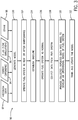
- FIG. 3 is a flow chart illustrating a method 90 for developing the operational model 54.
- the method 90 includes adapting historical data 92, adapting expert experience 94, and incorporating fluid flow simulations 96 and other 98 (e.g., any relevant information, data, and user/operator inputs) for generating model (step 100), wherein the model generated at step 100 is an initial model of the operational model 54 that is subjected to further training/updating.
- the historical data may include but not limited to speed pickup of fuel flow divider, fuel flow rate, fuel composition, fuel flow divider pressure, differential pressure across oil filter, fuel pump pressure, pump motor speed, pump current, pump voltage, temperature upstream and downstream of the fuel flow divider, exhaust spread data, ambient temperature, control valve stroke, turbine speed, turbine compressor mass flow rate, position feedback of stop valve, a nozzle flow number, a flow coefficient (Cv), a flow capacity rating, number of hours of loaded operation, purge duration, expert experience, or a combination thereof.
- the expert experience may be any user or operator inputs related to operation of the liquid fuel system 16 and/or the turbine system 10.
- the method 90 also includes operating the fuel system as new or after maintenance (step 102) and establishing a baseline (step 104) (e.g., for at least one physical parameter of a nozzle or valve associated with at least one combustor) at a particular time (e.g., when the fuel system is new or after a maintenance).
- the data used for establishing the baseline of the operational model 54 e.g., with baseline parameters
- the baseline may be at least one baseline parameter for at least one physical parameter of a fuel nozzle 12 or a valve associated with at least one combustor 20 of the liquid fuel system 16.
- the physical parameters may include a nozzle flow number, a flow coefficient (Cv), and a flow capacity rating, etc., for each individual combustor 20.
- the method 90 also includes operating fuel system as normal (step 106) and collecting data from the fuel system (step 108) while the turbine system 10 operates using the liquid fuel system 16, and providing collected data into the model to develop the operational model 54 of fuel system (step 110).
- the collected data herein may be operational parameters associated with the liquid fuel system 16 and/or the turbine system 10 collected via sensors (e.g., sensors 62, 64, 68, 70, 72, and 74) during operation of the gas turbine system 10 or physical parameters of the gas turbine system 10.
- the operational parameters may include but not limited to speed pickup of fuel flow divider, fuel flow rate, fuel composition, fuel flow divider pressure, differential pressure across oil filter, fuel pump pressure, pump motor speed, pump current, pump voltage, temperature upstream and downstream of the fuel flow divider, exhaust spread data, ambient temperature, control valve stroke, turbine speed, turbine compressor mass flow rate, number of hours of loaded operation, and purge duration, gas turbine exhaust temperature spread at part load and base load, etc.
- the physical parameters may include but not limited to position feedback of stop valve, nozzle flow number, a flow coefficient (Cv), and a flow capacity rating, etc.
- the operational model 54 may be developed based on data correlations between any of the physical or operational parameters set forth above. For example, a correlation may be established between a fuel flow rate and an exhaust spread. As a further example, a correlation may also be established between one or more physical parameters and one or more operational parameters. In addition, the operational model 54 may also be developed based on correlation between a variation in the one or more physical parameters to one or more operational parameters. Furthermore, the operational model 54 may be developed based additionally on operator/user input, and fluid flow simulations utilizing a physics based model that was created in system design phase.
- the method 90 further includes training and updating the model (step 112).
- the operational model 54 is operable to predict specific parameters, conditions, or changes in productivity of the liquid fuel system 16 based at least partially on data collected and correlations developed up to step 110 (e.g., steps 100 through step 110).
- the operational model 54 may be able to predict parameters such as flow rate, fuel composition, pressure drop at the flow divider 66, etc. at a future time.
- the operational model 54 may be able to predict conditions such as liquid fuel leakage, fuel cleanness, successful liquid fuel startup, etc. that may occur at a future time.
- the predictions made by the operational model 54 may be compared with the real situation/data for validation and training/updating of the operational model 54.
- the operational model 54 may also be trained and updated based on one or more physical or operational parameters set forth above.
- FIG. 4 is a flow chart illustrating a method 130 for utilizing the operational model 54.
- the method 130 includes beginning operation of the turbine system 10 (step 132), and performing diagnostics using the operational model 54 (step 134).
- operation conditions and parameters e.g., operational and physical parameters
- operation conditions and parameters may be fed into the operational model 54 in an in-situ or substantially in-situ manner, enabling the diagnostics module 76 issues diagnostics (e.g., reports, updates, etc.) of the overall health of the liquid fuel system 16.
- the diagnostics module 76 may determine that the gaseous fuel system 18 is not available, and the turbine system 10 can proceed to successful startup using the liquid fuel system 16.
- the diagnostics module 76 may also determine that the gaseous fuel system 18 is available, and the turbine system 10 can operate using only the gaseous fuel system 18. The diagnostics module 76 may advice the operator to transfer gaseous fuel system 18 to liquid fuel system 16 to operate turbine system 10, verse visa.
- the method 130 also includes performing predictions (step 138), providing maintenance recommendations (step 136), and adjusting an operation of at least one component of the liquid fuel system 16 (step 140) using the operational model 54.
- Concurrent with the turbine operation conditions and parameters are continuously fed into the operational model 54 to update the operational model 54 with the latest and concurrent conditions of the turbine system 10.
- the operational model 54 can predict the overall health state, the performance and/or specific parameters/conditions of the liquid fuel system 16 at future times.
- the operational model 54 may predict that particular component(s) of the liquid fuel system 16 (e.g., valves, nozzles, pumps, flow divider, etc.) may experience problems/issues in the future (e.g., in few days, weeks, months, or years).
- the operational model 54 may predict a probability of successful liquid fuel startup if the turbine system 10 would operate using only the liquid fuel system 16 in the future (e.g., in few days, weeks, months, or years).
- the operational model 54 may also be utilized for providing maintenance recommendations (step 136).
- the operational model 54 may be utilized for adjusting an operation of at least one component of the liquid fuel system (step 140).
- the operational model 54 may predict that certain issues/problems have occurred and sending commends (e.g., through the service platform 56 and/or through the controller 52) to shut down the operation of the turbine system 10.
- the operational model 54 may also adjusting operation of any components of the fluid fuel system 16.
- the operational model 54 may commend (e.g., commend signals sent through the service platform 56 and/or the controller 52) to increase or decrease the flow rate of the liquid fuel as to decrease the exhaust temperature spread of the turbine system 10.
Landscapes
- Engineering & Computer Science (AREA)
- Chemical & Material Sciences (AREA)
- Combustion & Propulsion (AREA)
- Physics & Mathematics (AREA)
- General Engineering & Computer Science (AREA)
- General Physics & Mathematics (AREA)
- Mechanical Engineering (AREA)
- Automation & Control Theory (AREA)
- Evolutionary Computation (AREA)
- Software Systems (AREA)
- Medical Informatics (AREA)
- Computer Vision & Pattern Recognition (AREA)
- Artificial Intelligence (AREA)
- Health & Medical Sciences (AREA)
- Quality & Reliability (AREA)
- Theoretical Computer Science (AREA)
- Computer Hardware Design (AREA)
- Geometry (AREA)
- Testing And Monitoring For Control Systems (AREA)
- Engine Equipment That Uses Special Cycles (AREA)
Description
- The present disclosure relates generally to power generation systems. In particular, the present disclosure relates to an operational model for a liquid fuel system.
- A dual-fuel combustion system can burn both gaseous fuel and liquid fuel. Typically, a dual-fuel turbine system operates using the gaseous fuel, and the liquid fuel is used as a backup fuel when the gaseous fuel is not available. During operation on gaseous fuel, the liquid fuel system is non-operational but may be remain filled with a stagnant volume of distillate liquid fuel. Under those conditions, corrosions and/or particle built-up can form along the surfaces of the liquid fuel system (e.g., in the flow divider, fuel nozzles, valves, etc.), which may cause erosion/corrosion of the flow divider, clogged valves, clogged nozzles, etc. These conditions may go unnoticed and result in decreased productivity and reliability of the combustion fuel system. While sensors may be installed to monitor certain parameters of the liquid fuel system, it is difficult for an operator to estimate the real situation of the liquid fuel system for planned power generation operations. As such, a predictive and self-diagnostic model of the liquid fuel system integrated with the power generation system may be desirable.
- Certain embodiments commensurate in scope with the originally claimed subject matter are summarized below. These embodiments are not intended to limit the scope of the claimed embodiments, but rather these embodiments are intended only to provide a brief summary of possible forms of the subject matter. Indeed, the presently claimed embodiments may encompass a variety of forms that may be similar to or different from the embodiments set forth below.
- In a first embodiment, a system for predicting performance of a liquid fuel system includes a processor and a memory communicatively coupled to the processor, wherein the memory stores instructions which when executed by the processor perform operations. The operations include establishing a baseline parameter for at least one physical parameter of a nozzle or a valve associated with at least one combustor of the liquid fuel system with at least one time. The operations also include obtaining one or more operational parameters associated with the liquid fuel system from one or more sensors during operation of a gas turbine engine. The operations further include utilizing an operational model of a fuel flow divider to output an action associated with the liquid fuel system based at least on the baseline parameter and the one or more operational parameters.
- In a second embodiment, a system for predicting performance of a liquid fuel system includes a gas turbine engine comprising a plurality of combustors and associated fuel nozzles, a fuel flow divider configured to regulate fuel flow to the associated fuel nozzles, a processor, and a memory communicatively coupled to the processor. The memory stores instructions which when executed by the processor perform operations including establishing a baseline parameter for at least one physical parameter of a respective nozzle or a respective valve associated with each combustor of the plurality combustors of the liquid fuel system with at least one time. The operations also include obtaining one or more operational parameters associated with the liquid fuel system from one or more sensors during operation of the gas turbine engine. The operations further include utilizing an operational model of the fuel flow divider to output an action associated with the liquid fuel system based at least on the baseline parameter and the one or more operational parameters.
- In a third embodiment, a non-transitory computer-readable medium has computer executable code stored thereon. The code includes instructions for establishing a baseline parameter for at least one physical parameter of a nozzle or a valve associated with at least one combustor of the liquid fuel system with at least one time. The code also includes obtaining one or more operational parameters associated with the liquid fuel system from one or more sensors during operation of a gas turbine engine. The code further includes utilizing an operational model of a fuel flow divider to output an action associated with the liquid fuel system based at least on the baseline parameter and the one or more operational parameters.
- These and other features, aspects, and advantages of the presently disclosed techniques will become better understood when the following detailed description is read with reference to the accompanying drawings in which like characters represent like parts throughout the drawings, wherein:
-
FIG. 1 is a schematic illustration of a turbine system, in accordance with an embodiment; -
FIG. 2 is a block diagram illustrating a smart liquid fuel system for predicting the overall health of a liquid fuel system of the turbine system, in accordance with an embodiment of the present disclosure; -
FIG. 3 is a flow chart illustrating a method for developing an operational model, in accordance with an embodiment of the present disclosure; and -
FIG. 4 is a flow chart illustrating a method for utilizing the operational model, in accordance with an embodiment of the present disclosure. - One or more specific embodiments of the presently disclosed embodiments will be described below. In an effort to provide a concise description of these embodiments, all features of an actual implementation may not be described in the specification. It should be appreciated that in the development of any such actual implementation, as in any engineering or design project, numerous implementation- specific decisions must be made to achieve the developers' specific goals, such as compliance with system-related and business-related constraints, which may vary from one implementation to another. Moreover, it should be appreciated that such a development effort might be complex and time consuming, but would nevertheless be a routine undertaking of design, fabrication, and manufacture for those of ordinary skill having the benefit of this disclosure.
- When introducing elements of various embodiments of the presently disclosed embodiments, the articles "a," "an," "the," and "said" are intended to mean that there are one or more of the elements. The terms "comprising," "including," and "having" are intended to be inclusive and mean that there may be additional elements other than the listed elements.
- As described below, model (e.g., operational model of fuel flow divider) may be developed to make diagnostics on the overall health of a liquid fuel system for a power generation system and make probability prediction of successful liquid fuel startup. The model may be updated and trained overtime to make more accurate diagnostics and predictions. The model for the liquid fuel system may be connected to a service platform (e.g., cloud computing service, distributed control system, etc.) to generate diagnostic/performance prediction reports, maintenance recommendations, and operation adjustments periodically. The model may be developed and updated based on parameters/conditions collected during operation of the power generation system, including but not limited to fuel composition, fuel cleanness, operation duration, and various operation data of the liquid fuel and power generation systems (fuel flow rate, fuel pump pressure, temperatures, power output, compress mass flow rate, etc.). In addition, correlation functions may be established between various parameters. For example, a correlation may be established for fuel flow rate and exhaust spread temperature. In one embodiment, a system for predicting performance of a liquid fuel system includes a processor and a memory communicatively coupled to the processor, wherein the memory stores instructions which when executed by the processor perform operations. The operations include establishing a baseline parameter for at least one physical parameter of a nozzle or a valve associated with at least one combustor of the liquid fuel system with at least one time. The operations also include obtaining one or more operational parameters associated with the liquid fuel system from one or more sensors during different operation modes of a gas turbine engine. The said operation modes include part load and base load. The operations further include utilizing an operational model of a fuel flow divider to output an action associated with the liquid fuel system based at least on the baseline parameter and the one or more operational parameters. As such, the model for the liquid fuel system with ability to self-diagnostics may be integrated into digital power plant to improve the power generation reliability and availability, and contribute to operation optimization and asset optimization.
-
FIG. 1 is a schematic of an embodiment of aturbine system 10. As described in detail below, the disclosed turbine system 10 (e.g., a gas turbine engine) may employ an end cover with fuel plenums, described below, which may improve fuel distribution and improve system durability, operability, and reliability. The turbine system (e.g., dual-fuel turbine system) 10 may use liquid or gas fuel, such as natural gas and/or a hydrogen rich synthetic gas, to drive theturbine system 10. As depicted, fuel nozzles 12 (e.g., multi-tube fuel nozzles) intake afuel supply 14 from aliquid fuel system 16 or agaseous fuel system 18, mix the fuel with an oxidant, such as air, oxygen, oxygen- enriched air, oxygen reduced air, or any combination thereof. Although the following discussion refers to the oxidant as the air, any suitable oxidant may be used with the disclosed embodiments. Once the fuel and air have been mixed, thefuel nozzles 12 distribute the fuel-air mixture into a plurality ofcombustors 20 in a suitable ratio for optimal combustion, emissions, fuel consumption, and power output. Theturbine system 10 may include one ormore fuel nozzles 12 located inside the plurality ofcombustors 20. The fuel-air mixture combusts in a chamber within each of the plurality ofcombustors 20, thereby creating hot pressurized exhaust gases. The plurality ofcombustors 20 direct the exhaust gases through aturbine 22 toward anexhaust outlet 24. As the exhaust gases pass through theturbine 22, the gases force turbine blades to rotate ashaft 26 along an axis of theturbine system 10. As illustrated, theshaft 26 may be connected to various components of theturbine system 10, including acompressor 28. Thecompressor 28 also includes blades coupled to theshaft 26. As theshaft 26 rotates, the blades within thecompressor 28 also rotate, thereby compressing air from anair intake 30 through thecompressor 28 and into thefuel nozzles 12 and/or the plurality ofcombustors 20. Theshaft 26 may also be connected to aload 32, which may be a vehicle or a stationary load, such as an electrical generator in a power plant or a propeller on an aircraft, for example. Theload 32 may include any suitable device capable of being powered by the rotational output of theturbine system 10. Theturbine system 10 may extend along an axial axis ordirection 34, a radial axis ordirection 36 toward or away from theaxis 30, and a circumferential axis ordirection 38 around theaxis 30. Thefuel nozzle 12 may contain or connect with an end cover having fuel plenums, described below, which may improve fuel distribution by feeding fuel directly into fuel injectors, which may feed fuel into tubes where it premixes with air before being released to the plurality ofcombustors 20. -
FIG. 2 is a block diagram illustrating a smartliquid fuel system 50 for predicting the overall health of theliquid fuel system 16 of theturbine system 10. The smartliquid fuel system 50 may include acontroller 52, an operational model 54 (e.g., of theliquid fuel system 16 and of thefuel flow divider 66 in particular), and a service platform 56 (e.g., cloud computing service, distributed control system, etc.). Thecontroller 52 is communicatively coupled (e.g., data transfer, receiving and giving instructions) with theservice platform 56, theoperational model 54, and various components and systems of the turbine system 10 (e.g.,liquid fuel system 16,flow divider 66 configured to regulate fuel flow to the associatedfuel nozzles 12, etc.) via wired or wireless network or communication system. In some embodiments, thecontroller 52 may be part of the service platform 56 (e.g., cloud computing service, distributed control system, etc.). Thecontroller 52 has aprocessor 58 and a memory 60 (e.g., a non-transitory computer-readable medium/memory circuitry) communicatively coupled to theprocessor 58, storing one or more sets of instructions (e.g., processor-executable instructions) implemented to perform operations related to theliquid fuel system 16. More specifically, thememory 60 may include volatile memory, such as random access memory (RAM), and/or non-volatile memory, such as read-only memory (ROM), optical drives, hard disc drives, or solid-state drives. Additionally, theprocessor 58 may include one or more application specific integrated circuits (ASICs), one or more field programmable gate arrays (FPGAs), one or more general purpose processors, or any combination thereof. Furthermore, the term processor is not limited to just those integrated circuits referred to in the art as processors, but broadly refers to computers, processors, microcontrollers, microcomputers, programmable logic controllers, application specific integrated circuits, and other programmable circuits. - For example, the
memory 60 may store instructions as to obtain information (e.g., physical parameters, operational parameters, operational conditions, etc.) from various components and systems of theturbine system 10 and the smartliquid fuel system 50, and store the obtained information in thememory 60. The information may be collected via one ormore sensors 62 of theliquid fuel system 16, one ormore sensors 64 of aflow divider 66, one ormore sensors 68 of the plurality ofcombustors 20, one ormore sensors 70 of theturbine 22, one ormore sensors 72 of theexhaust 24, and one or more sensor 74 disposed in close proximity to theturbine system 10. In addition, the information may also be inputted by operators or users (e.g., via thecontroller 52 and/or via the service platform 56). For example, the one ormore sensors - The
operational model 54 is communicatively coupled with thecontroller 52 to output an action associated with theliquid fuel system 16. Theoperational model 54 may predict the performance of the liquid fuel system 16 (e.g., successful liquid fuel startup, failure of a specific component such as fuel valve, nozzle, or combustor, etc.), make recommendation for maintenance of a component of the liquid fuel system 16 (e.g., specific fuel nozzle, flow divider, valve, or combustor, etc.), and adjust an operation of one or more components of theliquid fuel system 16. Furthermore, theoperational model 54 may include expert experiences, physics based models (e.g., to perform fluid flow simulations) and analytical models, a machine learning algorithm, an extrapolation model and so forth, such that theoperational model 54 can be updated and trained over time to be smarter (e.g., more accurate predictions, better recommendations, etc.). Furthermore, theoperational model 54 may include adiagnostics module 76, which may report current state of physical parameters of theliquid fuel system 16, report the overall health of theliquid fuel system 16, issue recommendations for maintenance, and/or issue or adjust an operation of one or more components of theliquid fuel system 16. For example thediagnostic module 76 may monitor and analyze the current operational conditions, parameters and data from theturbine system 10 and the liquid fuel system 16 (e.g., flowdivider 66,nozzles 12, etc.), and compare the analyzed results with the historical records. The current operational conditions, parameters and data may also be analyzed and compared with the predictions of theoperational model 54 and/or the expert experience. The diagnostics may be issued based on the comparison. In other embodiments, thediagnostic module 76 may also issue recommendations to adjust the operation conditions/parameters of the turbine system and the liquid fuel system 16 (e.g., flowdivider 66,nozzles 12, etc.) based on comparison. - It may be appreciated that the diagnostic results issued by the
diagnostic module 76 may also be fed back to theoperational model 54 to update/train theoperational model 54. In addition, theoperational model 54, thediagnostics module 76, and all data included thereof may be stored in thememory 60 of thecontroller 52. In other embodiments, theoperational model 54, thediagnostics module 76, and all data included thereof may be uploaded to theservice platform 56 and stored in the service platform 56 (e.g., upon instructed byprocessor 58 of the controller 52). Authorized users may have access to the data, results/reports, theoperational model 54, and thediagnostics module 76 through theservice platform 56. Authorized users may also provide customer/user experiences and expert experiences through theservice platform 56, and those information may be used to train/update theoperational model 54. As such, the smartliquid fuel system 50 is integrated into digital power plant to operation optimization, and online diagnostics may be available to increase reliability and availability of theturbine system 10. -
FIG. 3 is a flow chart illustrating amethod 90 for developing theoperational model 54. One or more of the steps of themethod 90 may be executed by thecontroller 52. Themethod 90 includes adaptinghistorical data 92, adaptingexpert experience 94, and incorporatingfluid flow simulations 96 and other 98 (e.g., any relevant information, data, and user/operator inputs) for generating model (step 100), wherein the model generated atstep 100 is an initial model of theoperational model 54 that is subjected to further training/updating. The historical data may include but not limited to speed pickup of fuel flow divider, fuel flow rate, fuel composition, fuel flow divider pressure, differential pressure across oil filter, fuel pump pressure, pump motor speed, pump current, pump voltage, temperature upstream and downstream of the fuel flow divider, exhaust spread data, ambient temperature, control valve stroke, turbine speed, turbine compressor mass flow rate, position feedback of stop valve, a nozzle flow number, a flow coefficient (Cv), a flow capacity rating, number of hours of loaded operation, purge duration, expert experience, or a combination thereof. The expert experience may be any user or operator inputs related to operation of theliquid fuel system 16 and/or theturbine system 10. Themethod 90 also includes operating the fuel system as new or after maintenance (step 102) and establishing a baseline (step 104) (e.g., for at least one physical parameter of a nozzle or valve associated with at least one combustor) at a particular time (e.g., when the fuel system is new or after a maintenance). The data used for establishing the baseline of the operational model 54 (e.g., with baseline parameters) are data collected while the theliquid fuel system 16 is in operation right after a brandnew flow divider 66 is newly installed or right after a major maintenance event of theliquid fuel system 16. Specifically, the baseline may be at least one baseline parameter for at least one physical parameter of afuel nozzle 12 or a valve associated with at least onecombustor 20 of theliquid fuel system 16. Specifically, the physical parameters may include a nozzle flow number, a flow coefficient (Cv), and a flow capacity rating, etc., for eachindividual combustor 20. - The
method 90 also includes operating fuel system as normal (step 106) and collecting data from the fuel system (step 108) while theturbine system 10 operates using theliquid fuel system 16, and providing collected data into the model to develop theoperational model 54 of fuel system (step 110). The collected data herein may be operational parameters associated with theliquid fuel system 16 and/or theturbine system 10 collected via sensors (e.g.,sensors gas turbine system 10 or physical parameters of thegas turbine system 10. The operational parameters may include but not limited to speed pickup of fuel flow divider, fuel flow rate, fuel composition, fuel flow divider pressure, differential pressure across oil filter, fuel pump pressure, pump motor speed, pump current, pump voltage, temperature upstream and downstream of the fuel flow divider, exhaust spread data, ambient temperature, control valve stroke, turbine speed, turbine compressor mass flow rate, number of hours of loaded operation, and purge duration, gas turbine exhaust temperature spread at part load and base load, etc. The physical parameters may include but not limited to position feedback of stop valve, nozzle flow number, a flow coefficient (Cv), and a flow capacity rating, etc. - The
operational model 54 may be developed based on data correlations between any of the physical or operational parameters set forth above. For example, a correlation may be established between a fuel flow rate and an exhaust spread. As a further example, a correlation may also be established between one or more physical parameters and one or more operational parameters. In addition, theoperational model 54 may also be developed based on correlation between a variation in the one or more physical parameters to one or more operational parameters. Furthermore, theoperational model 54 may be developed based additionally on operator/user input, and fluid flow simulations utilizing a physics based model that was created in system design phase. - The
method 90 further includes training and updating the model (step 112). At this stage, theoperational model 54 is operable to predict specific parameters, conditions, or changes in productivity of theliquid fuel system 16 based at least partially on data collected and correlations developed up to step 110 (e.g., steps 100 through step 110). For example, theoperational model 54 may be able to predict parameters such as flow rate, fuel composition, pressure drop at theflow divider 66, etc. at a future time. For example, theoperational model 54 may be able to predict conditions such as liquid fuel leakage, fuel cleanness, successful liquid fuel startup, etc. that may occur at a future time. The predictions made by theoperational model 54 may be compared with the real situation/data for validation and training/updating of theoperational model 54. In addition, theoperational model 54 may also be trained and updated based on one or more physical or operational parameters set forth above. -
FIG. 4 is a flow chart illustrating amethod 130 for utilizing theoperational model 54. One or more of the steps of themethod 130 may be executed by thecontroller 52. Themethod 130 includes beginning operation of the turbine system 10 (step 132), and performing diagnostics using the operational model 54 (step 134). Upon beginning operation of theturbine system 10, operation conditions and parameters (e.g., operational and physical parameters) may be fed into theoperational model 54 in an in-situ or substantially in-situ manner, enabling thediagnostics module 76 issues diagnostics (e.g., reports, updates, etc.) of the overall health of theliquid fuel system 16. Thediagnostics module 76 may determine that thegaseous fuel system 18 is not available, and theturbine system 10 can proceed to successful startup using theliquid fuel system 16. Thediagnostics module 76 may also determine that thegaseous fuel system 18 is available, and theturbine system 10 can operate using only thegaseous fuel system 18. Thediagnostics module 76 may advice the operator to transfergaseous fuel system 18 toliquid fuel system 16 to operateturbine system 10, verse visa. - The
method 130 also includes performing predictions (step 138), providing maintenance recommendations (step 136), and adjusting an operation of at least one component of the liquid fuel system 16 (step 140) using theoperational model 54. Concurrent with the turbine operation, conditions and parameters are continuously fed into theoperational model 54 to update theoperational model 54 with the latest and concurrent conditions of theturbine system 10. Accordingly, theoperational model 54 can predict the overall health state, the performance and/or specific parameters/conditions of theliquid fuel system 16 at future times. For example, theoperational model 54 may predict that particular component(s) of the liquid fuel system 16 (e.g., valves, nozzles, pumps, flow divider, etc.) may experience problems/issues in the future (e.g., in few days, weeks, months, or years). For example, theoperational model 54 may predict a probability of successful liquid fuel startup if theturbine system 10 would operate using only theliquid fuel system 16 in the future (e.g., in few days, weeks, months, or years). - As mentioned, the
operational model 54 may also be utilized for providing maintenance recommendations (step 136). For example, as theoperational model 54 is communicatively coupled to theservice platform 56 if it was predicted that certain components(s) such as valves, nozzles, pumps, flow divider, etc., may experience problems/issues after some time period (e.g., in few days, weeks, months, or years, etc.), theoperational model 54 would issue maintenance recommendations (e.g., communicated through theservice platform 56 to users/operators, etc.) to fix or replace the component(s) before the occurrence of the predicted issues/problems. In addition, theoperational model 54 may be utilized for adjusting an operation of at least one component of the liquid fuel system (step 140). For example, theoperational model 54 may predict that certain issues/problems have occurred and sending commends (e.g., through theservice platform 56 and/or through the controller 52) to shut down the operation of theturbine system 10. Theoperational model 54 may also adjusting operation of any components of thefluid fuel system 16. For example, theoperational model 54 may commend (e.g., commend signals sent through theservice platform 56 and/or the controller 52) to increase or decrease the flow rate of the liquid fuel as to decrease the exhaust temperature spread of theturbine system 10. - This written description uses examples to describe the present embodiments, and also to enable any person skilled in the art to practice the presently disclosed embodiments, including making and using any devices or systems and performing any incorporated methods. The patentable scope of the presently disclosed embodiments is defined by the claims, and may include other examples that occur to those skilled in the art. Such other examples are intended to be within the scope of the claims if they have structural elements that do not differ from the literal language of the claims, or if they include equivalent structural elements with insubstantial differences from the literal languages of the claims.
- Various aspects and embodiments of the present invention are defined by the following numbered clauses:
- 1. A system for predicting performance of a liquid fuel system, comprising:
- a processor;
- a memory communicatively coupled to the processor, wherein the memory stores instructions which when executed by the processor perform operations comprising:
- establishing a baseline parameter for at least one physical parameter of a nozzle or a valve associated with at least one combustor of the liquid fuel system with at least one time;
- obtaining one or more operational parameters associated with the liquid fuel system from one or more sensors during operation of a gas turbine engine; and
- utilizing an operational model of a fuel flow divider to output an action associated with the liquid fuel system based at least on the baseline parameter and the one or more operational parameters.
- 2. The system of clause 1, wherein the action comprises a prediction of the performance of the liquid fuel system.
- 3. The system of any preceding clause, wherein the action comprises a recommendation for maintenance of a component of the liquid fuel system.
- 4. The system of any preceding clause, wherein the action comprises a control action to adjust an operation of at least one component of the liquid fuel system.
- 5. The system of any preceding clause, wherein the at least one time is associated with commissioning of the liquid fuel system.
- 6. The system of any preceding clause, wherein the at least one time is associated with a scheduled maintenance of the liquid fuel system.
- 7. The system of any preceding clause, wherein the instructions which when executed by the processor perform operations comprising generating the operational model of the fuel flow divider based on at least historical data.
- 8. The system of any preceding clause, wherein the historical data comprises speed pickup of fuel flow divider, fuel flow rate, fuel flow divider pressure, temperature upstream and downstream of the fuel flow divider, or number of hours of loaded operation, purge duration, or a combination thereof.
- 9. The system of any preceding clause, wherein the instructions which when executed by the processor perform operations comprising generating the operational model of the fuel flow divider based additionally on operator input, fluid flow simulations utilizing a physics based model, fuel composition, or differential pressure across oil filter, or a combination thereof.
- 10. The system of any preceding clause, wherein the one or more operational parameters comprise speed pickup of fuel flow divider, fuel flow rate, fuel flow divider pressure, temperature upstream and downstream of the fuel flow divider, exhaust spread data, or number of hours of loaded operation, purge duration, or a combination thereof.
- 11. The system of any preceding clause, wherein the instructions which when executed by the processor perform operations comprising updating the operational model of the fuel flow divider based on the one or more operational parameters.
- 12. The system of any preceding clause, wherein the instructions which when executed by the processor perform operations comprising utilizing the operational model of the fuel flow divider in correlating a fuel flow rate to an exhaust spread.
- 13. The system of any preceding clause, wherein the instructions which when executed by the processor perform operations comprising utilizing the operational model of the fuel flow divider in correlating a variation in the at least one physical parameter to the one or more operational parameters.
- 14. A system for predicting performance of a liquid fuel system, comprising:
- a gas turbine engine comprising a plurality of combustors and associated fuel nozzles;
- a fuel flow divider configured to regulate fuel flow to the associated fuel nozzles;
- a processor;
- a memory communicatively coupled to the processor, the memory storing instructions which when executed by the processor perform operations comprising:
- establishing a baseline parameter for at least one physical parameter of a respective nozzle or a respective valve associated with each combustor of the plurality combustors of the liquid fuel system with at least one time;
- obtaining one or more operational parameters associated with the liquid fuel system from one or more sensors during operation of the gas turbine engine; and
- utilizing an operational model of the fuel flow divider to output an action associated with the liquid fuel system based at least on the baseline parameter and the one or more operational parameters.
- 15. The system of any preceding clause, wherein the at least one physical parameter comprises a nozzle flow number for the respective nozzle.
- 16. The system of any preceding clause, wherein the at least one physical parameter comprises a flow coefficient, Cv, for the respective valve.
- 17. The system of any preceding clause, wherein the instructions which when executed by the processor perform operations comprising utilizing the operational model of the fuel flow divider in correlating a variation in the at least one physical parameter to the one or more operational parameters.
- 18. The system of any preceding clause, wherein the at least one time is associated with commissioning of the liquid fuel system or a scheduled maintenance of the liquid fuel system.
- 19. The system of any preceding clause, wherein the instructions which when executed by the processor perform operations comprising updating the operational model of the fuel flow divider based on the one or more operational parameters.
- 20. A non-transitory computer-readable medium having computer executable code stored thereon, the code comprising instructions for:
- establishing a baseline parameter for at least one physical parameter of a nozzle or a valve associated with at least one combustor of the liquid fuel system with at least one time;
- obtaining one or more operational parameters associated with the liquid fuel system from one or more sensors during operation of a gas turbine engine; and
- utilizing an operational model of a fuel flow divider to output an action associated with the liquid fuel system based at least on the baseline parameter and the one or more operational parameters.
Claims (15)
- A system for predicting performance of a liquid fuel system, comprising:a processor;a memory communicatively coupled to the processor, wherein the memory stores instructions which when executed by the processor perform operations comprising:establishing a baseline parameter for at least one physical parameter of a nozzle or a valve associated with at least one combustor of the liquid fuel system with atleast one time;obtaining one or more operational parameters associated with the liquid fuel system from one or more sensors during operation of a gas turbine engine; andutilizing an operational model of a fuel flow divider to output an action associated with the liquid fuel system based at least on the baseline parameter and the one or more operational parameters.
- The system of claim 1, wherein the action comprises a prediction of the performance of the liquid fuel system.
- The system of claim 1, wherein the action comprises a recommendation for maintenance of a component of the liquid fuel system.
- The system of claim 1, wherein the action comprises a control action to adjust an operation of at least one component of the liquid fuel system.
- The system of any preceding claim, wherein the at least one time is associated with commissioning of the liquid fuel system.
- The system of any of claims 1 to 4, wherein the at least one time is associated with a scheduled maintenance of the liquid fuel system.
- The system of any preceding claim, wherein the instructions which when executed by the processor perform operations comprising generating the operational model of the fuel flow divider based on at least historical data.
- The system of any preceding claim, wherein the historical data comprises speed pickup of fuel flow divider, fuel flow rate, fuel flow divider pressure, temperature upstream and downstream of the fuel flow divider, or number of hours of loaded operation, purge duration, or a combination thereof.
- The system of any of claims 1 to 6, wherein the instructions which when executed by the processor perform operations comprising generating the operational model of the fuel flow divider based additionally on operator input, fluid flow simulations utilizing a physics based model, fuel composition, or differential pressure across oil filter, or a combination thereof.
- The system of any preceding claim, wherein the one or more operational parameters comprise speed pickup of fuel flow divider, fuel flow rate, fuel flow divider pressure, temperature upstream and downstream of the fuel flow divider, exhaust spread data, or number of hours of loaded operation, purge duration, or a combination thereof.
- The system of any preceding claim, wherein the instructions which when executed by the processor perform operations comprising updating the operational model of the fuel flow divider based on the one or more operational parameters.
- The system of any of claims 1 to 10, wherein the instructions which when executed by the processor perform operations comprising utilizing the operational model of the fuel flow divider in correlating a fuel flow rate to an exhaust spread.
- The system of any of claims 1 to 10, wherein the instructions which when executed by the processor perform operations comprising utilizing the operational model of the fuel flow divider in correlating a variation in the at least one physical parameter to the one or more operational parameters.
- A system for predicting performance of a liquid fuel system, comprising:a gas turbine engine comprising a plurality of combustors and associated fuel nozzles;
a fuel flow divider configured to regulate fuel flow to the associated fuel nozzles;a processor;a memory communicatively coupled to the processor, the memory storing instructions which when executed by the processor perform operations comprising:establishing a baseline parameter for at least one physical parameter of a respective nozzle or a respective valve associated with each combustor of the plurality combustors of the liquid fuel system with at least one time;obtaining one or more operational parameters associated with the liquid fuel system from one or more sensors during operation of the gas turbine engine; andutilizing an operational model of the fuel flow divider to output an action associated with the liquid fuel system based at least on the baseline parameter and the one or more operational parameters. - A non-transitory computer-readable medium having computer executable code stored thereon, the code comprising instructions for:establishing a baseline parameter for at least one physical parameter of a nozzle or a valve associated with at least one combustor of the liquid fuel system with at least one time;obtaining one or more operational parameters associated with the liquid fuel system from one or more sensors during operation of a gas turbine engine; andutilizing an operational model of a fuel flow divider to output an action associated with the liquid fuel system based at least on the baseline parameter and the one or more operational parameters.
Applications Claiming Priority (1)
| Application Number | Priority Date | Filing Date | Title |
|---|---|---|---|
| US15/270,612 US10233846B2 (en) | 2016-09-20 | 2016-09-20 | Smart liquid fuel system with ability to self-diagnostics |
Publications (2)
| Publication Number | Publication Date |
|---|---|
| EP3296825A1 true EP3296825A1 (en) | 2018-03-21 |
| EP3296825B1 EP3296825B1 (en) | 2020-12-30 |
Family
ID=60009410
Family Applications (1)
| Application Number | Title | Priority Date | Filing Date |
|---|---|---|---|
| EP17190799.1A Active EP3296825B1 (en) | 2016-09-20 | 2017-09-13 | Smart liquid fuel system with ability to self-diagnostics |
Country Status (4)
| Country | Link |
|---|---|
| US (1) | US10233846B2 (en) |
| EP (1) | EP3296825B1 (en) |
| JP (1) | JP7019352B2 (en) |
| CN (1) | CN107842426B (en) |
Families Citing this family (7)
| Publication number | Priority date | Publication date | Assignee | Title |
|---|---|---|---|---|
| US11137361B2 (en) * | 2018-09-18 | 2021-10-05 | Rosemount Inc. | Process vessel insulation monitoring |
| US11377223B2 (en) * | 2018-10-29 | 2022-07-05 | Pratt & Whitney Canada Corp. | Autothrottle control system on turbopropeller-powered aircraft |
| US20200158026A1 (en) * | 2018-11-19 | 2020-05-21 | Pratt & Whitney Canada Corp. | Engine optimization biased to high fuel flow rate |
| CN111241650B (en) * | 2018-11-27 | 2023-04-14 | 宁波方太厨具有限公司 | Optimizing Method of Burner Performance Parameters Based on DOE Experiment |
| US10739755B1 (en) | 2019-01-31 | 2020-08-11 | Baker Hughes Oilfield Operations Llc | Industrial machine optimization |
| US11713723B2 (en) | 2019-05-15 | 2023-08-01 | Pratt & Whitney Canada Corp. | Method and system for operating an engine |
| US11760500B2 (en) | 2019-11-11 | 2023-09-19 | Pratt & Whitney Canada Corp. | Systems and methods for filling a fuel manifold of a gas turbine engine |
Citations (5)
| Publication number | Priority date | Publication date | Assignee | Title |
|---|---|---|---|---|
| US20050107942A1 (en) * | 2003-10-30 | 2005-05-19 | Masumi Nomura | Gas turbine control apparatus, gas turbine system and gas turbine control method |
| US20080178600A1 (en) * | 2007-01-26 | 2008-07-31 | General Electric Company | Systems and Methods for Initializing Dynamic Model States Using a Kalman Filter |
| EP2570616A2 (en) * | 2011-09-15 | 2013-03-20 | General Electric Company | System and method for simulating a gas turbine compressor |
| US20150007574A1 (en) * | 2013-07-08 | 2015-01-08 | General Electric Company | Systems and methods for control of a gas turbine |
| US20150160096A1 (en) * | 2013-12-05 | 2015-06-11 | General Electric Company | System and Method for Detecting an At-Fault Combustor |
Family Cites Families (17)
| Publication number | Priority date | Publication date | Assignee | Title |
|---|---|---|---|---|
| US3738104A (en) * | 1971-07-16 | 1973-06-12 | Gen Electric | Gas turbine fuel flow metering control system |
| US4328824A (en) * | 1979-12-10 | 1982-05-11 | General Electric Company | Flow divider with plural metering gears, unrestrained spacers there-between and lubricated end roller bearings |
| WO2002103177A1 (en) * | 2001-06-18 | 2002-12-27 | Hitachi, Ltd. | Method and system for diagnosing state of gas turbine |
| US7950238B2 (en) * | 2006-10-26 | 2011-05-31 | General Electric Company | Method for detecting onset of uncontrolled fuel in a gas turbine combustor |
| US7891192B2 (en) | 2007-08-28 | 2011-02-22 | General Electric Company | Gas turbine engine combustor assembly having integrated control valves |
| US8478473B2 (en) | 2008-07-28 | 2013-07-02 | General Electric Company | Method and systems for controlling gas turbine engine temperature |
| FR2939924B1 (en) * | 2008-12-15 | 2012-10-12 | Snecma | IDENTIFICATION OF FAILURES IN AN AIRCRAFT ENGINE |
| US20120070266A1 (en) | 2010-09-21 | 2012-03-22 | General Electric Company | Turbo-machine temperature control |
| US20130068307A1 (en) * | 2011-09-20 | 2013-03-21 | General Electric Company | System and method for monitoring fuel at forwarding skid for gas turbine engine |
| US9181878B2 (en) * | 2011-12-19 | 2015-11-10 | Honeywell International Inc. | Operations support systems and methods for calculating and evaluating engine emissions |
| US9149776B2 (en) * | 2012-07-13 | 2015-10-06 | General Electric Company | Systems and methods for liquid fuel modeling |
| US9765643B2 (en) | 2012-12-19 | 2017-09-19 | United Technologies Corporation | Bi-directional auxiliary lubrication system |
| US20150226129A1 (en) | 2014-02-10 | 2015-08-13 | General Electric Company | Method for Detecting Hazardous Gas Concentrations within a Gas Turbine Enclosure |
| JP6217451B2 (en) * | 2014-02-26 | 2017-10-25 | 三菱日立パワーシステムズ株式会社 | Fuel control device, combustor, gas turbine, control method and program |
| US9506835B2 (en) | 2014-04-23 | 2016-11-29 | General Electric Company | Fuel leak detection system for use in a turbine enclosure |
| US10975776B2 (en) * | 2016-04-07 | 2021-04-13 | Raytheon Technologies Corporation | Adaptive fuel flow estimation with flow meter feedback |
| US20170328567A1 (en) * | 2016-05-11 | 2017-11-16 | United Technologies Corporation | Multivariable fuel control and estimator (mfce) for preventing combustor blowout |
-
2016
- 2016-09-20 US US15/270,612 patent/US10233846B2/en active Active
-
2017
- 2017-09-08 JP JP2017172578A patent/JP7019352B2/en active Active
- 2017-09-13 EP EP17190799.1A patent/EP3296825B1/en active Active
- 2017-09-20 CN CN201710854624.3A patent/CN107842426B/en active Active
Patent Citations (5)
| Publication number | Priority date | Publication date | Assignee | Title |
|---|---|---|---|---|
| US20050107942A1 (en) * | 2003-10-30 | 2005-05-19 | Masumi Nomura | Gas turbine control apparatus, gas turbine system and gas turbine control method |
| US20080178600A1 (en) * | 2007-01-26 | 2008-07-31 | General Electric Company | Systems and Methods for Initializing Dynamic Model States Using a Kalman Filter |
| EP2570616A2 (en) * | 2011-09-15 | 2013-03-20 | General Electric Company | System and method for simulating a gas turbine compressor |
| US20150007574A1 (en) * | 2013-07-08 | 2015-01-08 | General Electric Company | Systems and methods for control of a gas turbine |
| US20150160096A1 (en) * | 2013-12-05 | 2015-06-11 | General Electric Company | System and Method for Detecting an At-Fault Combustor |
Also Published As
| Publication number | Publication date |
|---|---|
| US10233846B2 (en) | 2019-03-19 |
| JP2018048628A (en) | 2018-03-29 |
| JP7019352B2 (en) | 2022-02-15 |
| EP3296825B1 (en) | 2020-12-30 |
| CN107842426B (en) | 2022-06-07 |
| US20180080390A1 (en) | 2018-03-22 |
| CN107842426A (en) | 2018-03-27 |
Similar Documents
| Publication | Publication Date | Title |
|---|---|---|
| EP3296825B1 (en) | Smart liquid fuel system with ability to self-diagnostics | |
| US10386259B2 (en) | Hazgas system with acoustic wave sensors | |
| JP6250942B2 (en) | System and method for operation with improved reliability | |
| US9014945B2 (en) | Online enhancement for improved gas turbine performance | |
| JP6878108B2 (en) | Systems and methods for modeling engine power output | |
| JP6514725B2 (en) | System and method for predicting physical parameters for a fuel combustion system | |
| JP2017146299A (en) | Automated system and method for generating engine test cell analytics and diagnostics | |
| CN106050435B (en) | Regulation and control systems, computer program products and methods for gas turbines | |
| CN105604703B (en) | Computing device, system and method for tuning a gas turbine | |
| EP2865865B1 (en) | Method and system for gas turbine power augmentation using steam injection | |
| US9500136B2 (en) | Systems and methods for generating variable ramp rates for turbomachinery | |
| US9599032B2 (en) | Application of probabilistic control in gas turbine tuning for emissions-fuel flow parameters, related control systems, computer program products and methods | |
| US9599033B2 (en) | Application of probabilistic control in gas turbine tuning for fuel flow-exhaust energy parameters, related control systems, computer program products and methods | |
| US9599030B2 (en) | Application of probabilistic control in gas turbine tuning for exhaust energy-fuel flow parameters, related control systems, computer program products and methods | |
| EP3081786B1 (en) | Application of probabilistic control in gas turbine tuning for exhaust energy-emissions parameters, related control systems and computer porgram. | |
| Asif | The simulation and analysis of fault diagnosis and isolation for gas turbine control system |
Legal Events
| Date | Code | Title | Description |
|---|---|---|---|
| PUAI | Public reference made under article 153(3) epc to a published international application that has entered the european phase |
Free format text: ORIGINAL CODE: 0009012 |
|
| STAA | Information on the status of an ep patent application or granted ep patent |
Free format text: STATUS: THE APPLICATION HAS BEEN PUBLISHED |
|
| AK | Designated contracting states |
Kind code of ref document: A1 Designated state(s): AL AT BE BG CH CY CZ DE DK EE ES FI FR GB GR HR HU IE IS IT LI LT LU LV MC MK MT NL NO PL PT RO RS SE SI SK SM TR |
|
| AX | Request for extension of the european patent |
Extension state: BA ME |
|
| STAA | Information on the status of an ep patent application or granted ep patent |
Free format text: STATUS: REQUEST FOR EXAMINATION WAS MADE |
|
| 17P | Request for examination filed |
Effective date: 20180921 |
|
| RBV | Designated contracting states (corrected) |
Designated state(s): AL AT BE BG CH CY CZ DE DK EE ES FI FR GB GR HR HU IE IS IT LI LT LU LV MC MK MT NL NO PL PT RO RS SE SI SK SM TR |
|
| STAA | Information on the status of an ep patent application or granted ep patent |
Free format text: STATUS: EXAMINATION IS IN PROGRESS |
|
| 17Q | First examination report despatched |
Effective date: 20190926 |
|
| GRAP | Despatch of communication of intention to grant a patent |
Free format text: ORIGINAL CODE: EPIDOSNIGR1 |
|
| STAA | Information on the status of an ep patent application or granted ep patent |
Free format text: STATUS: GRANT OF PATENT IS INTENDED |
|
| RIC1 | Information provided on ipc code assigned before grant |
Ipc: G05B 17/02 20060101AFI20200709BHEP Ipc: G05B 13/04 20060101ALI20200709BHEP Ipc: G05B 23/02 20060101ALI20200709BHEP Ipc: F02C 9/40 20060101ALI20200709BHEP Ipc: F02C 9/28 20060101ALI20200709BHEP |
|
| INTG | Intention to grant announced |
Effective date: 20200728 |
|
| GRAS | Grant fee paid |
Free format text: ORIGINAL CODE: EPIDOSNIGR3 |
|
| GRAA | (expected) grant |
Free format text: ORIGINAL CODE: 0009210 |
|
| STAA | Information on the status of an ep patent application or granted ep patent |
Free format text: STATUS: THE PATENT HAS BEEN GRANTED |
|
| AK | Designated contracting states |
Kind code of ref document: B1 Designated state(s): AL AT BE BG CH CY CZ DE DK EE ES FI FR GB GR HR HU IE IS IT LI LT LU LV MC MK MT NL NO PL PT RO RS SE SI SK SM TR |
|
| REG | Reference to a national code |
Ref country code: GB Ref legal event code: FG4D |
|
| REG | Reference to a national code |
Ref country code: AT Ref legal event code: REF Ref document number: 1350552 Country of ref document: AT Kind code of ref document: T Effective date: 20210115 |
|
| REG | Reference to a national code |
Ref country code: DE Ref legal event code: R096 Ref document number: 602017030339 Country of ref document: DE |
|
| REG | Reference to a national code |
Ref country code: IE Ref legal event code: FG4D |
|
| PG25 | Lapsed in a contracting state [announced via postgrant information from national office to epo] |
Ref country code: GR Free format text: LAPSE BECAUSE OF FAILURE TO SUBMIT A TRANSLATION OF THE DESCRIPTION OR TO PAY THE FEE WITHIN THE PRESCRIBED TIME-LIMIT Effective date: 20210331 Ref country code: FI Free format text: LAPSE BECAUSE OF FAILURE TO SUBMIT A TRANSLATION OF THE DESCRIPTION OR TO PAY THE FEE WITHIN THE PRESCRIBED TIME-LIMIT Effective date: 20201230 Ref country code: NO Free format text: LAPSE BECAUSE OF FAILURE TO SUBMIT A TRANSLATION OF THE DESCRIPTION OR TO PAY THE FEE WITHIN THE PRESCRIBED TIME-LIMIT Effective date: 20210330 Ref country code: RS Free format text: LAPSE BECAUSE OF FAILURE TO SUBMIT A TRANSLATION OF THE DESCRIPTION OR TO PAY THE FEE WITHIN THE PRESCRIBED TIME-LIMIT Effective date: 20201230 |
|
| REG | Reference to a national code |
Ref country code: AT Ref legal event code: MK05 Ref document number: 1350552 Country of ref document: AT Kind code of ref document: T Effective date: 20201230 |
|
| PG25 | Lapsed in a contracting state [announced via postgrant information from national office to epo] |
Ref country code: SE Free format text: LAPSE BECAUSE OF FAILURE TO SUBMIT A TRANSLATION OF THE DESCRIPTION OR TO PAY THE FEE WITHIN THE PRESCRIBED TIME-LIMIT Effective date: 20201230 Ref country code: BG Free format text: LAPSE BECAUSE OF FAILURE TO SUBMIT A TRANSLATION OF THE DESCRIPTION OR TO PAY THE FEE WITHIN THE PRESCRIBED TIME-LIMIT Effective date: 20210330 Ref country code: LV Free format text: LAPSE BECAUSE OF FAILURE TO SUBMIT A TRANSLATION OF THE DESCRIPTION OR TO PAY THE FEE WITHIN THE PRESCRIBED TIME-LIMIT Effective date: 20201230 |
|
| REG | Reference to a national code |
Ref country code: NL Ref legal event code: MP Effective date: 20201230 |
|
| PG25 | Lapsed in a contracting state [announced via postgrant information from national office to epo] |
Ref country code: HR Free format text: LAPSE BECAUSE OF FAILURE TO SUBMIT A TRANSLATION OF THE DESCRIPTION OR TO PAY THE FEE WITHIN THE PRESCRIBED TIME-LIMIT Effective date: 20201230 |
|
| REG | Reference to a national code |
Ref country code: LT Ref legal event code: MG9D |
|
| PG25 | Lapsed in a contracting state [announced via postgrant information from national office to epo] |
Ref country code: SK Free format text: LAPSE BECAUSE OF FAILURE TO SUBMIT A TRANSLATION OF THE DESCRIPTION OR TO PAY THE FEE WITHIN THE PRESCRIBED TIME-LIMIT Effective date: 20201230 Ref country code: PT Free format text: LAPSE BECAUSE OF FAILURE TO SUBMIT A TRANSLATION OF THE DESCRIPTION OR TO PAY THE FEE WITHIN THE PRESCRIBED TIME-LIMIT Effective date: 20210430 Ref country code: RO Free format text: LAPSE BECAUSE OF FAILURE TO SUBMIT A TRANSLATION OF THE DESCRIPTION OR TO PAY THE FEE WITHIN THE PRESCRIBED TIME-LIMIT Effective date: 20201230 Ref country code: CZ Free format text: LAPSE BECAUSE OF FAILURE TO SUBMIT A TRANSLATION OF THE DESCRIPTION OR TO PAY THE FEE WITHIN THE PRESCRIBED TIME-LIMIT Effective date: 20201230 Ref country code: EE Free format text: LAPSE BECAUSE OF FAILURE TO SUBMIT A TRANSLATION OF THE DESCRIPTION OR TO PAY THE FEE WITHIN THE PRESCRIBED TIME-LIMIT Effective date: 20201230 Ref country code: LT Free format text: LAPSE BECAUSE OF FAILURE TO SUBMIT A TRANSLATION OF THE DESCRIPTION OR TO PAY THE FEE WITHIN THE PRESCRIBED TIME-LIMIT Effective date: 20201230 |
|
| PG25 | Lapsed in a contracting state [announced via postgrant information from national office to epo] |
Ref country code: PL Free format text: LAPSE BECAUSE OF FAILURE TO SUBMIT A TRANSLATION OF THE DESCRIPTION OR TO PAY THE FEE WITHIN THE PRESCRIBED TIME-LIMIT Effective date: 20201230 Ref country code: AT Free format text: LAPSE BECAUSE OF FAILURE TO SUBMIT A TRANSLATION OF THE DESCRIPTION OR TO PAY THE FEE WITHIN THE PRESCRIBED TIME-LIMIT Effective date: 20201230 |
|
| PG25 | Lapsed in a contracting state [announced via postgrant information from national office to epo] |
Ref country code: IS Free format text: LAPSE BECAUSE OF FAILURE TO SUBMIT A TRANSLATION OF THE DESCRIPTION OR TO PAY THE FEE WITHIN THE PRESCRIBED TIME-LIMIT Effective date: 20210430 |
|
| REG | Reference to a national code |
Ref country code: DE Ref legal event code: R097 Ref document number: 602017030339 Country of ref document: DE |
|
| PG25 | Lapsed in a contracting state [announced via postgrant information from national office to epo] |
Ref country code: AL Free format text: LAPSE BECAUSE OF FAILURE TO SUBMIT A TRANSLATION OF THE DESCRIPTION OR TO PAY THE FEE WITHIN THE PRESCRIBED TIME-LIMIT Effective date: 20201230 |
|
| PLBE | No opposition filed within time limit |
Free format text: ORIGINAL CODE: 0009261 |
|
| STAA | Information on the status of an ep patent application or granted ep patent |
Free format text: STATUS: NO OPPOSITION FILED WITHIN TIME LIMIT |
|
| PG25 | Lapsed in a contracting state [announced via postgrant information from national office to epo] |
Ref country code: DK Free format text: LAPSE BECAUSE OF FAILURE TO SUBMIT A TRANSLATION OF THE DESCRIPTION OR TO PAY THE FEE WITHIN THE PRESCRIBED TIME-LIMIT Effective date: 20201230 |
|
| 26N | No opposition filed |
Effective date: 20211001 |
|
| PG25 | Lapsed in a contracting state [announced via postgrant information from national office to epo] |
Ref country code: ES Free format text: LAPSE BECAUSE OF FAILURE TO SUBMIT A TRANSLATION OF THE DESCRIPTION OR TO PAY THE FEE WITHIN THE PRESCRIBED TIME-LIMIT Effective date: 20201230 |
|
| PG25 | Lapsed in a contracting state [announced via postgrant information from national office to epo] |
Ref country code: SI Free format text: LAPSE BECAUSE OF FAILURE TO SUBMIT A TRANSLATION OF THE DESCRIPTION OR TO PAY THE FEE WITHIN THE PRESCRIBED TIME-LIMIT Effective date: 20201230 |
|
| REG | Reference to a national code |
Ref country code: CH Ref legal event code: PL |
|
| REG | Reference to a national code |
Ref country code: BE Ref legal event code: MM Effective date: 20210930 |
|
| GBPC | Gb: european patent ceased through non-payment of renewal fee |
Effective date: 20210913 |
|
| PG25 | Lapsed in a contracting state [announced via postgrant information from national office to epo] |
Ref country code: IS Free format text: LAPSE BECAUSE OF FAILURE TO SUBMIT A TRANSLATION OF THE DESCRIPTION OR TO PAY THE FEE WITHIN THE PRESCRIBED TIME-LIMIT Effective date: 20210430 Ref country code: MC Free format text: LAPSE BECAUSE OF FAILURE TO SUBMIT A TRANSLATION OF THE DESCRIPTION OR TO PAY THE FEE WITHIN THE PRESCRIBED TIME-LIMIT Effective date: 20201230 |
|
| PG25 | Lapsed in a contracting state [announced via postgrant information from national office to epo] |
Ref country code: LU Free format text: LAPSE BECAUSE OF NON-PAYMENT OF DUE FEES Effective date: 20210913 Ref country code: IE Free format text: LAPSE BECAUSE OF NON-PAYMENT OF DUE FEES Effective date: 20210913 Ref country code: GB Free format text: LAPSE BECAUSE OF NON-PAYMENT OF DUE FEES Effective date: 20210913 Ref country code: FR Free format text: LAPSE BECAUSE OF NON-PAYMENT OF DUE FEES Effective date: 20210930 Ref country code: BE Free format text: LAPSE BECAUSE OF NON-PAYMENT OF DUE FEES Effective date: 20210930 |
|
| PG25 | Lapsed in a contracting state [announced via postgrant information from national office to epo] |
Ref country code: LI Free format text: LAPSE BECAUSE OF NON-PAYMENT OF DUE FEES Effective date: 20210930 Ref country code: CH Free format text: LAPSE BECAUSE OF NON-PAYMENT OF DUE FEES Effective date: 20210930 |
|
| PG25 | Lapsed in a contracting state [announced via postgrant information from national office to epo] |
Ref country code: HU Free format text: LAPSE BECAUSE OF FAILURE TO SUBMIT A TRANSLATION OF THE DESCRIPTION OR TO PAY THE FEE WITHIN THE PRESCRIBED TIME-LIMIT; INVALID AB INITIO Effective date: 20170913 |
|
| PG25 | Lapsed in a contracting state [announced via postgrant information from national office to epo] |
Ref country code: NL Free format text: LAPSE BECAUSE OF NON-PAYMENT OF DUE FEES Effective date: 20201230 Ref country code: CY Free format text: LAPSE BECAUSE OF FAILURE TO SUBMIT A TRANSLATION OF THE DESCRIPTION OR TO PAY THE FEE WITHIN THE PRESCRIBED TIME-LIMIT Effective date: 20201230 |
|
| PG25 | Lapsed in a contracting state [announced via postgrant information from national office to epo] |
Ref country code: SM Free format text: LAPSE BECAUSE OF FAILURE TO SUBMIT A TRANSLATION OF THE DESCRIPTION OR TO PAY THE FEE WITHIN THE PRESCRIBED TIME-LIMIT Effective date: 20201230 |
|
| REG | Reference to a national code |
Ref country code: DE Ref legal event code: R081 Ref document number: 602017030339 Country of ref document: DE Owner name: GENERAL ELECTRIC TECHNOLOGY GMBH, CH Free format text: FORMER OWNER: GENERAL ELECTRIC COMPANY, SCHENECTADY, NY, US |
|
| PG25 | Lapsed in a contracting state [announced via postgrant information from national office to epo] |
Ref country code: MK Free format text: LAPSE BECAUSE OF FAILURE TO SUBMIT A TRANSLATION OF THE DESCRIPTION OR TO PAY THE FEE WITHIN THE PRESCRIBED TIME-LIMIT Effective date: 20201230 |
|
| PG25 | Lapsed in a contracting state [announced via postgrant information from national office to epo] |
Ref country code: TR Free format text: LAPSE BECAUSE OF FAILURE TO SUBMIT A TRANSLATION OF THE DESCRIPTION OR TO PAY THE FEE WITHIN THE PRESCRIBED TIME-LIMIT Effective date: 20201230 |
|
| PG25 | Lapsed in a contracting state [announced via postgrant information from national office to epo] |
Ref country code: MT Free format text: LAPSE BECAUSE OF FAILURE TO SUBMIT A TRANSLATION OF THE DESCRIPTION OR TO PAY THE FEE WITHIN THE PRESCRIBED TIME-LIMIT Effective date: 20201230 |
|
| PGFP | Annual fee paid to national office [announced via postgrant information from national office to epo] |
Ref country code: DE Payment date: 20250820 Year of fee payment: 9 |
|
| PGFP | Annual fee paid to national office [announced via postgrant information from national office to epo] |
Ref country code: IT Payment date: 20250820 Year of fee payment: 9 |