EP3296804A1 - Modulation pattern calculation device, light control device, modulation pattern calculation method, modulation pattern calculation program, and storage medium - Google Patents
Modulation pattern calculation device, light control device, modulation pattern calculation method, modulation pattern calculation program, and storage medium Download PDFInfo
- Publication number
- EP3296804A1 EP3296804A1 EP16796372.7A EP16796372A EP3296804A1 EP 3296804 A1 EP3296804 A1 EP 3296804A1 EP 16796372 A EP16796372 A EP 16796372A EP 3296804 A1 EP3296804 A1 EP 3296804A1
- Authority
- EP
- European Patent Office
- Prior art keywords
- function
- fourier transform
- waveform
- modulation pattern
- spectrum
- Prior art date
- Legal status (The legal status is an assumption and is not a legal conclusion. Google has not performed a legal analysis and makes no representation as to the accuracy of the status listed.)
- Granted
Links
Images






Classifications
-
- H—ELECTRICITY
- H01—ELECTRIC ELEMENTS
- H01S—DEVICES USING THE PROCESS OF LIGHT AMPLIFICATION BY STIMULATED EMISSION OF RADIATION [LASER] TO AMPLIFY OR GENERATE LIGHT; DEVICES USING STIMULATED EMISSION OF ELECTROMAGNETIC RADIATION IN WAVE RANGES OTHER THAN OPTICAL
- H01S3/00—Lasers, i.e. devices using stimulated emission of electromagnetic radiation in the infrared, visible or ultraviolet wave range
- H01S3/005—Optical devices external to the laser cavity, specially adapted for lasers, e.g. for homogenisation of the beam or for manipulating laser pulses, e.g. pulse shaping
- H01S3/0085—Modulating the output, i.e. the laser beam is modulated outside the laser cavity
-
- G—PHYSICS
- G02—OPTICS
- G02F—OPTICAL DEVICES OR ARRANGEMENTS FOR THE CONTROL OF LIGHT BY MODIFICATION OF THE OPTICAL PROPERTIES OF THE MEDIA OF THE ELEMENTS INVOLVED THEREIN; NON-LINEAR OPTICS; FREQUENCY-CHANGING OF LIGHT; OPTICAL LOGIC ELEMENTS; OPTICAL ANALOGUE/DIGITAL CONVERTERS
- G02F1/00—Devices or arrangements for the control of the intensity, colour, phase, polarisation or direction of light arriving from an independent light source, e.g. switching, gating or modulating; Non-linear optics
- G02F1/01—Devices or arrangements for the control of the intensity, colour, phase, polarisation or direction of light arriving from an independent light source, e.g. switching, gating or modulating; Non-linear optics for the control of the intensity, phase, polarisation or colour
- G02F1/0121—Operation of devices; Circuit arrangements, not otherwise provided for in this subclass
-
- G—PHYSICS
- G02—OPTICS
- G02F—OPTICAL DEVICES OR ARRANGEMENTS FOR THE CONTROL OF LIGHT BY MODIFICATION OF THE OPTICAL PROPERTIES OF THE MEDIA OF THE ELEMENTS INVOLVED THEREIN; NON-LINEAR OPTICS; FREQUENCY-CHANGING OF LIGHT; OPTICAL LOGIC ELEMENTS; OPTICAL ANALOGUE/DIGITAL CONVERTERS
- G02F1/00—Devices or arrangements for the control of the intensity, colour, phase, polarisation or direction of light arriving from an independent light source, e.g. switching, gating or modulating; Non-linear optics
- G02F1/01—Devices or arrangements for the control of the intensity, colour, phase, polarisation or direction of light arriving from an independent light source, e.g. switching, gating or modulating; Non-linear optics for the control of the intensity, phase, polarisation or colour
- G02F1/13—Devices or arrangements for the control of the intensity, colour, phase, polarisation or direction of light arriving from an independent light source, e.g. switching, gating or modulating; Non-linear optics for the control of the intensity, phase, polarisation or colour based on liquid crystals, e.g. single liquid crystal display cells
-
- G—PHYSICS
- G02—OPTICS
- G02F—OPTICAL DEVICES OR ARRANGEMENTS FOR THE CONTROL OF LIGHT BY MODIFICATION OF THE OPTICAL PROPERTIES OF THE MEDIA OF THE ELEMENTS INVOLVED THEREIN; NON-LINEAR OPTICS; FREQUENCY-CHANGING OF LIGHT; OPTICAL LOGIC ELEMENTS; OPTICAL ANALOGUE/DIGITAL CONVERTERS
- G02F1/00—Devices or arrangements for the control of the intensity, colour, phase, polarisation or direction of light arriving from an independent light source, e.g. switching, gating or modulating; Non-linear optics
- G02F1/01—Devices or arrangements for the control of the intensity, colour, phase, polarisation or direction of light arriving from an independent light source, e.g. switching, gating or modulating; Non-linear optics for the control of the intensity, phase, polarisation or colour
- G02F1/13—Devices or arrangements for the control of the intensity, colour, phase, polarisation or direction of light arriving from an independent light source, e.g. switching, gating or modulating; Non-linear optics for the control of the intensity, phase, polarisation or colour based on liquid crystals, e.g. single liquid crystal display cells
- G02F1/133—Constructional arrangements; Operation of liquid crystal cells; Circuit arrangements
-
- G—PHYSICS
- G05—CONTROLLING; REGULATING
- G05B—CONTROL OR REGULATING SYSTEMS IN GENERAL; FUNCTIONAL ELEMENTS OF SUCH SYSTEMS; MONITORING OR TESTING ARRANGEMENTS FOR SUCH SYSTEMS OR ELEMENTS
- G05B15/00—Systems controlled by a computer
- G05B15/02—Systems controlled by a computer electric
-
- G—PHYSICS
- G06—COMPUTING OR CALCULATING; COUNTING
- G06F—ELECTRIC DIGITAL DATA PROCESSING
- G06F17/00—Digital computing or data processing equipment or methods, specially adapted for specific functions
- G06F17/10—Complex mathematical operations
- G06F17/14—Fourier, Walsh or analogous domain transformations, e.g. Laplace, Hilbert, Karhunen-Loeve, transforms
-
- G—PHYSICS
- G02—OPTICS
- G02F—OPTICAL DEVICES OR ARRANGEMENTS FOR THE CONTROL OF LIGHT BY MODIFICATION OF THE OPTICAL PROPERTIES OF THE MEDIA OF THE ELEMENTS INVOLVED THEREIN; NON-LINEAR OPTICS; FREQUENCY-CHANGING OF LIGHT; OPTICAL LOGIC ELEMENTS; OPTICAL ANALOGUE/DIGITAL CONVERTERS
- G02F2203/00—Function characteristic
- G02F2203/12—Function characteristic spatial light modulator
Definitions
- An aspect of the present invention relates to a modulation pattern calculation apparatus, a light control apparatus, a modulation pattern calculation method, a modulation pattern calculation program, and a computer readable medium.
- Non Patent Document 1 discloses technology for modulating a phase spectrum using a spatial light modulator (SLM) to shape a light pulse.
- SLM spatial light modulator
- a phase spectrum to obtain a desired light pulse waveform is calculated using an iterative Fourier method (iterative Fourier transform algorithm: IFTA).
- IFTA iterative Fourier transform algorithm
- Non Patent Document 2 discloses an iterative Fourier method modified to avoid a solution from being led to a local solution, in phase spectrum modulation to shape a light pulse.
- a modulation pattern to give, to the light, a phase spectrum and an intensity spectrum (or one of them) to bring the temporal waveform of the light close to a desired waveform is presented on the SLM.
- Non Patent Document 1 When these spectra are obtained by the calculation, the iterative Fourier method is used as described in Non Patent Document 1, for example.
- the iterative Fourier method there is a problem in that a solution may be led to a local solution, and an optimal solution is not necessarily obtained.
- Non Patent Document 2 a difference between a desired waveform and a waveform after a Fourier transform is multiplied by a predetermined coefficient, a result is added to the desired waveform, and an iterative Fourier operation is performed.
- the solution may be led to the local solution.
- An object of one aspect of the present invention is to provide a modulation pattern calculation apparatus, a light control apparatus, a modulation pattern calculation method, a modulation pattern calculation program, and a computer readable medium capable of preventing a solution from being led to a local solution during an iterative Fourier operation and accurately calculating an intensity spectrum or a phase spectrum to bring a temporal waveform of light close to a desired waveform.
- a modulation pattern calculation apparatus is an apparatus for calculating a modulation pattern presented on a spatial light modulator for modulating at least one of an intensity spectrum and a phase spectrum of input light to bring a temporal intensity waveform of light close to a desired waveform
- the apparatus includes an iterative Fourier transform unit for performing a Fourier transform on a waveform function in a frequency domain including an intensity spectrum function and a phase spectrum function, performing a first replacement of a temporal intensity waveform function based on the desired waveform in a time domain after the Fourier transform and then performing an inverse Fourier transform, and performing a second replacement to constrain one spectrum function of the intensity spectrum function and the phase spectrum function in the frequency domain after the inverse Fourier transform, and a modulation pattern calculation unit for calculating the modulation pattern on the basis of the other spectrum function output from the iterative Fourier transform unit.
- the iterative Fourier transform unit performs the first replacement using a result of multiplying a function representing the desired waveform by a coefficient.
- the coefficient has a value in which a difference between the function after the multiplication and the temporal intensity waveform function after the Fourier transform is smaller than a difference before the multiplication of the coefficient.
- a modulation pattern calculation method is a method for calculating a modulation pattern presented on a spatial light modulator for modulating at least one of an intensity spectrum and a phase spectrum of input light to bring a temporal intensity waveform of light close to a desired waveform
- the method includes a step (Fourier transform step) of performing a Fourier transform on a waveform function in a frequency domain including an intensity spectrum function and a phase spectrum function, a step (inverse Fourier transform step) of performing a first replacement of a temporal intensity waveform function based on the desired waveform in a time domain after the Fourier transform and then performing an inverse Fourier transform, a step (replacement step) of performing a second replacement to constrain one spectrum function of the intensity spectrum function and the phase spectrum function in the frequency domain after the inverse Fourier transform, and a step (modulation pattern calculation step) of calculating the modulation pattern on the basis of the other spectrum function output in the step of performing the second replacement.
- the first replacement is performed using a result of multiplying a function representing the desired waveform by a coefficient.
- the coefficient has a value in which a difference between the function after the multiplication and the temporal intensity waveform function after the Fourier transform is smaller than a difference before the multiplication of the coefficient.
- a modulation pattern calculation program is a program for causing a computer to calculate a modulation pattern presented on a spatial light modulator for modulating at least one of an intensity spectrum and a phase spectrum of input light to bring a temporal intensity waveform of light close to a desired waveform, and the program causes the computer to execute a step (Fourier transform step) of performing a Fourier transform on a waveform function in a frequency domain including an intensity spectrum function and a phase spectrum function, a step (inverse Fourier transform step) of performing a first replacement of a temporal intensity waveform function based on the desired waveform in a time domain after the Fourier transform and then performing an inverse Fourier transform, a step (replacement step) of performing a second replacement to constrain one spectrum function of the intensity spectrum function and the phase spectrum function in the frequency domain after the inverse Fourier transform, and a step (modulation pattern calculation step) of calculating the modulation pattern on the basis of the other spectrum function output in the step of performing the second
- the first replacement is performed using a result of multiplying a function representing the desired waveform by a coefficient.
- the coefficient has a value in which a difference between the function after the multiplication and the temporal intensity waveform function after the Fourier transform is smaller than a difference before the multiplication of the coefficient.
- the intensity spectrum or the phase spectrum to bring the temporal intensity waveform of the light close to the desired waveform is calculated in the iterative Fourier transform unit or the replacement step.
- a solution may be led to a local solution and an optimal solution is not necessarily obtained. Therefore, in the above apparatus and the method, when the replacement based on the desired waveform is performed on the temporal intensity waveform function in the time domain obtained by the Fourier transform, the result of multiplying the function representing the desired waveform by the coefficient is used.
- the coefficient has the value in which the difference between the function after the multiplication and the temporal intensity waveform function after the Fourier transform is smaller than the difference before the multiplication of the coefficient.
- the intensity spectrum or the phase spectrum to bring the temporal waveform of the light close to the desired waveform can be accurately calculated.
- a light control apparatus includes the modulation pattern calculation apparatus having the above configuration, a light source for outputting the input light, a dispersive element for spectrally dispersing the input light, a spatial light modulator for modulating at least one of an intensity spectrum and a phase spectrum of the input light after the dispersion and outputting modulated light, and an optical system for focusing the modulated light.
- the spatial light modulator presents the modulation pattern calculated by the modulation pattern calculation apparatus.
- the modulation pattern calculation apparatus having the above configuration is included, so that the solution can be prevented from being led to the local solution during an iterative Fourier operation and the intensity spectrum or the phase spectrum to bring the temporal waveform of the light close to the desired waveform can be accurately calculated.
- a solution can be prevented from being led to a local solution during an iterative Fourier operation, and an intensity spectrum or a phase spectrum to bring a temporal waveform of light close to a desired waveform can be accurately calculated.
- FIG. 1 is a diagram schematically illustrating a configuration of a light control apparatus 1A according to an embodiment of the present invention.
- the light control apparatus 1A according to the present embodiment generates, from input light La, output light Ld having an arbitrary temporal intensity waveform different from that of the input light La.
- the light control apparatus 1A includes a light source 2, an optical system 10, and a modulation pattern calculation apparatus 20.
- the light source 2 outputs the input light La input to the optical system 10.
- the light source 2 is a laser light source such as a solid-state laser light source, for example, and the input light La is coherent pulse light, for example.
- the optical system 10 has a dispersive element 12, a curved mirror 14, and an SLM 16.
- the dispersive element 12 is optically coupled to the light source 2, and the SLM 16 is optically coupled to the dispersive element 12 via the curved mirror 14.
- the dispersive element 12 spectrally disperses the input light La for each wavelength component.
- the dispersive element 12 has a diffraction grating formed on a plate surface, for example. Further, the dispersive element 12 may have a prism.
- the input light La is obliquely incident on the diffraction grating, and is spectrally dispersed into a plurality of wavelength components.
- Light Lb including the plurality of wavelength components reaches the curved mirror 14.
- the light Lb is reflected by the curved mirror 14 and reaches the SLM 16.
- the SLM 16 simultaneously performs phase modulation and intensity modulation of the light Lb to generate the output light Ld having an arbitrary temporal intensity waveform different from the waveform of the input light La.
- the SLM 16 is of a phase modulation type, for example.
- the SLM 16 is of an LCOS (liquid crystal on silicon) type.
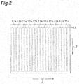
- FIG. 2 is a diagram illustrating a modulation plane 17 of the SLM 16.
- a plurality of modulation regions 17a are arranged along a certain direction A, and each modulation region 17a extends in a direction B intersecting with the direction A.
- the direction A is a dispersing direction by the dispersive element 12. Therefore, each of the spectrally dispersed wavelength components is incident on each of the plurality of modulation regions 17a.
- the SLM 16 modulates a phase and an intensity of each incident wavelength component in each modulation region 17a. Because the SLM 16 in the present embodiment is of the phase modulation type, the intensity modulation is realized by a phase pattern (phase image) presented on the modulation plane 17.
- Modulated light Lc including the respective wavelength components modulated by the SLM 16 is reflected again by the curved mirror 14 and reaches the dispersive element 12.
- the curved mirror 14 functions as a focusing optical system for focusing the modulated light Lc.
- the dispersive element 12 functions as a combining optical system and combines the respective wavelength components after the modulation. That is, by the curved mirror 14 and the dispersive element 12, the plurality of wavelength components of the modulated light Lc are focused and combined with each other and become the output light Ld.
- the output light Ld is light having a desired temporal intensity waveform different from the waveform of the input light La.
- the modulation pattern calculation apparatus 20 is a computer having an operation circuit such as a processor.
- the modulation pattern calculation apparatus 20 is electrically coupled to the SLM 16, calculates a phase modulation pattern to bring the temporal intensity waveform of the output light Ld close to a desired waveform, and provides a control signal including the phase modulation pattern to the SLM 16.
- the modulation pattern calculation apparatus 20 of the present embodiment presents, on the SLM 16, a phase pattern including a phase pattern for phase modulation that gives a phase spectrum for obtaining the desired waveform to the output light Ld and a phase pattern for intensity modulation that gives an intensity spectrum for obtaining the desired waveform to the output light Ld.
- the modulation pattern calculation apparatus 20 includes an arbitrary waveform input unit 21, a phase spectrum design unit 22, an intensity spectrum design unit 23, and a modulation pattern calculation unit 24.
- the operation circuit for example, the processor of the computer
- the respective functions may be realized by the same operation circuit or may be realized by different operation circuits.
- the operation circuit (for example, the processor of the computer) can realize the above respective functions by a modulation pattern calculation program. Therefore, the modulation pattern calculation program operates the operation circuit (for example, the processor of the computer) as the arbitrary waveform input unit 21, the phase spectrum design unit 22, the intensity spectrum design unit 23, and the modulation pattern calculation unit 24 in the modulation pattern calculation apparatus 20.
- the modulation pattern calculation program is stored in a storage device (non-transitory computer readable medium) inside or outside the computer.
- the arbitrary waveform input unit 21 receives the desired temporal intensity waveform input from an operator.
- the operator inputs information (for example, a pulse width) on the desired temporal intensity waveform to the arbitrary waveform input unit 21.
- the information on the desired temporal intensity waveform is given to the phase spectrum design unit 22 and the intensity spectrum design unit 23.
- the phase spectrum design unit 22 calculates a corresponding phase spectrum of the output light Ld, on the basis of the temporal intensity waveform.
- the intensity spectrum design unit 23 calculates a corresponding intensity spectrum of the output light Ld, on the basis of the temporal intensity waveform.
- the modulation pattern calculation unit 24 is an example of a modulation pattern calculation unit according to one aspect of the present invention and calculates a phase modulation pattern to give the phase spectrum obtained in the phase spectrum design unit 22 and the intensity spectrum obtained in the intensity spectrum design unit 23 to the output light Ld. Further, a control signal including the calculated phase modulation pattern is provided to the SLM 16.
- FIG. 3 is a graph illustrating an example of a combination of a certain phase spectrum G11 and a certain intensity spectrum G12.
- FIG. 3 is a graph illustrating a temporal intensity waveform of the output light Ld realized by the combination of the phase spectrum and the intensity spectrum illustrated in (a) in FIG. 3 .
- a horizontal axis shows a wavelength (nm)
- a left vertical axis shows an intensity value (arbitrary unit) of the intensity spectrum
- a right vertical axis shows a phase value (rad) of the phase spectrum.
- a horizontal axis shows a time (femtosecond) and a vertical axis shows a light intensity (arbitrary unit).
- the spectra and the waveform illustrated in FIG. 3 are examples, and the temporal intensity waveform of the output light Ld can be controlled in various forms by combinations of various phase spectra and intensity spectra.
- the desired temporal intensity waveform is represented as a function in a time domain, and the phase spectrum and the intensity spectrum are represented as functions in a frequency domain. Therefore, the phase spectrum and the intensity spectrum corresponding to the desired temporal intensity waveform are obtained by an iterative Fourier transform based on the desired temporal intensity waveform. In the method described below, the phase spectrum and the intensity spectrum are calculated using an iterative Fourier transform method. Therefore, as illustrated in FIG. 1 , the phase spectrum design unit 22 has an iterative Fourier transform unit 22a. Further, the intensity spectrum design unit 23 has an iterative Fourier transform unit 23a.
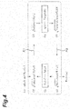
- FIG. 4 illustrates a calculation procedure of a phase spectrum using the normal iterative Fourier method, as a first comparative example for the present embodiment.
- a waveform function (a) in the frequency domain including the intensity spectrum function A 0 ( ⁇ ) and the phase spectrum function ⁇ n ( ⁇ ) is prepared (process number (2) in the drawing).
- a subscript n represents after an n-th Fourier transform process.
- phase spectrum form represented by the phase spectrum function ⁇ n ( ⁇ ) in the waveform function can be brought close to a phase spectrum form corresponding to the desired temporal intensity waveform.
- a phase spectrum function ⁇ IFTA ( ⁇ ) to be finally obtained is used to calculate the modulation pattern.
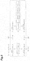
- FIG. 5 illustrates a calculation procedure of a phase spectrum using an iterative Fourier method (hereinafter, referred to as IFTA-Fienup) described in Non Patent Document 2, as a second comparative example for the present embodiment.
- IFTA-Fienup an iterative Fourier method
- Target n (t) ⁇ Target 0 t + ⁇ Target 0 t ⁇ b n t 0, if Target 0 t + ⁇ Target 0 t ⁇ b n t ⁇ 0
- FIG. 6 illustrates a calculation procedure of a phase spectrum using the improved iterative Fourier method in the present embodiment.
- the iterative Fourier transform unit 22a prepares a waveform function (i) in the frequency domain including the intensity spectrum function A 0 ( ⁇ ) and the phase spectrum function ⁇ n ( ⁇ ) (process number (2) in the drawing).
- a subscript n represents after an n-th Fourier transform process.
- i is an imaginary number.
- the iterative Fourier transform unit 22a performs the Fourier transform from the frequency domain to the time domain on the function (i).
- a waveform function (j) in the frequency domain including the temporal intensity waveform function b n (t) is obtained (process number (3) in the drawing).
- the iterative Fourier transform unit 22a calculates a coefficient ⁇ in which a difference between the waveform function b n (t) after the Fourier transform and a result ( ⁇ ⁇ Target 0 (t)) of multiplying the function Target 0 (t) by the coefficient ⁇ becomes smaller than a difference between the waveform function b n (t) and the function Target 0 (t) (process number (4) in the drawing).
- a coefficient ⁇ in which a standard deviation ⁇ of ⁇ ⁇ Target 0 (t) with respect to the waveform function b n (t) after the Fourier transform becomes a minimum ( ⁇ min ) is derived by searching.
- D represents the number of data points and ts and te represent a start point and an end point of a time axis, respectively.
- the iterative Fourier transform unit 22a performs a replacement based on the desired waveform on the temporal intensity waveform function b n (t) included in the function (j) after the Fourier transform (first replacement). At this time, the iterative Fourier transform unit 22a performs the replacement using the result ( ⁇ ⁇ Target 0 (t)) of multiplying the function Target 0 (t) representing the desired waveform by the coefficient ⁇ .
- the replacement is performed by Target n (t) calculated by the formula (m) obtained by replacing Target 0 (t) in the formula (g) in IFTA-Fienup described above by ⁇ ⁇ Target 0 (t) (process numbers (5) and (6) in the drawing).
- Target n t ⁇ ⁇ ⁇ Target 0 t + ⁇ ⁇ ⁇ Target 0 t ⁇ b n t 0, if ⁇ ⁇ Target 0 t + ⁇ ⁇ ⁇ Target 0 t ⁇ b n t ⁇ 0
- the iterative Fourier transform unit 22a performs the inverse Fourier transform from the time domain to the frequency domain on the function (n) (arrow A2 in the drawing).
- a waveform function (o) in the frequency domain including the intensity spectrum function B n ( ⁇ ) and the phase spectrum function ⁇ n ( ⁇ ) is obtained (process number (7) in the drawing).
- the iterative Fourier transform unit 22a repeatedly performs the above processes (1) to (8) a plurality of times, so that the phase spectrum form represented by the phase spectrum function ⁇ n ( ⁇ ) in the waveform function can be brought close to a phase spectrum form corresponding to the desired temporal intensity waveform.
- a phase spectrum function ⁇ IFTA ( ⁇ ) to be finally obtained is provided to the modulation pattern calculation unit 24.
- FIG. 7 illustrates a calculation procedure in the iterative Fourier transform unit 23a of the intensity spectrum design unit 23.
- the iterative Fourier transform unit 23a calculates an intensity spectrum by the similar method as the calculation method by the iterative Fourier transform unit 22a described above.
- the iterative Fourier transform unit 23a prepares a waveform function (q) in the frequency domain including an intensity spectrum function A k ( ⁇ ) and the phase spectrum function ⁇ 0 ( ⁇ ) (process number (2) in the drawing).
- a subscript k represents after a k-th Fourier transform process.
- the iterative Fourier transform unit 23a performs the Fourier transform from the frequency domain to the time domain on the function (q).
- a waveform function (r) in the frequency domain including a temporal intensity waveform function b k (t) is obtained (process number (3) in the drawing).
- the iterative Fourier transform unit 23a calculates a coefficient ⁇ in which a difference between the waveform function b k (t) after the Fourier transform and a result ( ⁇ ⁇ Target 0 (t)) of multiplying the function Target 0 (t) by the coefficient ⁇ becomes smaller than a difference between the waveform function b k (t) and the function Target 0 (t) (process number (4) in the drawing).
- a coefficient ⁇ in which a standard deviation ⁇ of ⁇ ⁇ Target 0 (t) with respect to the waveform function b k (t) after the Fourier transform becomes a minimum ( ⁇ min ) is derived by searching.
- D represents the number of data points and ts and te represent a start point and an end point of a time axis, respectively.
- the iterative Fourier transform unit 23a performs a replacement based on the desired waveform on the temporal intensity waveform function b k (t) included in the function (r) after the Fourier transform (first replacement). At this time, the iterative Fourier transform unit 23a performs the replacement using the result ( ⁇ ⁇ Target 0 (t)) of multiplying the function Target 0 (t) representing the desired waveform by the coefficient a. In one example, the replacement is performed by Target k (t) calculated by the formula (t) (process numbers (5) and (6) in the drawing).
- Target k t ⁇ ⁇ ⁇ Target 0 t + ⁇ ⁇ ⁇ Target 0 t ⁇ b k t 0, if ⁇ ⁇ Target 0 t + ⁇ ⁇ ⁇ Target 0 t ⁇ b k t ⁇ 0
- the iterative Fourier transform unit 23a performs the inverse Fourier transform from the time domain to the frequency domain on the function (u).
- a waveform function (v) in the frequency domain including an intensity spectrum function C k ( ⁇ ) and a phase spectrum function ⁇ k ( ⁇ ) is obtained (process number (7) in the drawing).
- the iterative Fourier transform unit 23a to constrain the phase spectrum function ⁇ k ( ⁇ ) included in the function (v), replaces the function by the initial phase spectrum function ⁇ 0 ( ⁇ ) (second replacement, process number (8) in the drawing).
- ⁇ k ⁇ : ⁇ 0 ⁇
- the iterative Fourier transform unit 23a repeatedly performs the above processes (1) to (8) a plurality of times, so that the phase spectrum form represented by the intensity spectrum function A k ( ⁇ ) in the waveform function can be brought close to an intensity spectrum form corresponding to the desired temporal intensity waveform.
- An intensity spectrum function A IFTA ( ⁇ ) to be finally obtained is provided to the modulation pattern calculation unit 24.
- FIG. 8 is a flowchart illustrating a modulation pattern calculation method realized by the modulation pattern calculation apparatus 20 described above. As illustrated in FIG 8 , first, information on a desired temporal intensity waveform is input to the arbitrary waveform input unit 21 by the operator (input step S1). Next, a phase spectrum and an intensity spectrum to bring the temporal intensity waveform close to a desired waveform are calculated in the phase spectrum design unit 22 and the intensity spectrum design unit 23, respectively (phase spectrum calculation step S11 and intensity spectrum calculation step S21).
- An iterative Fourier transform step S12 by the iterative Fourier transform unit 22a is included in the phase spectrum calculation step S11.
- the Fourier transform is performed on the waveform function (formula (i)) in the frequency domain including the intensity spectrum function A 0 ( ⁇ ) and the phase spectrum function ⁇ n ( ⁇ ), the replacement of the temporal intensity waveform function based on the desired waveform is performed in the time domain after the Fourier transform (formulas (m) and (n)), and the replacement to constrain the intensity spectrum function is performed in the frequency domain after the inverse Fourier transform (formula (p)).
- these processes are repeatedly performed a plurality of times, so that the phase spectrum function ⁇ n ( ⁇ ) is brought close to a phase spectrum form corresponding to the desired waveform.
- a phase spectrum function ⁇ IFTA ( ⁇ ) to be finally obtained is provided to a next modulation pattern calculation step S3.
- an iterative Fourier transform step S22 by the iterative Fourier transform unit 23a is included in the intensity spectrum calculation step S21.
- the Fourier transform is performed on the waveform function (formula (q)) in the frequency domain including the intensity spectrum function A k ( ⁇ ) and the phase spectrum function ⁇ 0 ( ⁇ )
- the replacement of the temporal intensity waveform function based on the desired waveform is performed in the time domain after the Fourier transform (formulas (t) and (u))
- the replacement to constrain the phase spectrum function is performed in the frequency domain after the inverse Fourier transform (formula (w)).
- these processes are repeatedly performed a plurality of times, so that the intensity spectrum function A k ( ⁇ ) is brought close to an intensity spectrum form corresponding to the desired waveform.
- An intensity spectrum function A IFTA ( ⁇ ) to be finally obtained is provided to the next modulation pattern calculation step S3.
- a modulation pattern is calculated on the basis of the phase spectrum function ⁇ IFTA ( ⁇ ) and the intensity spectrum function ⁇ IFTA ( ⁇ ).
- the modulation pattern is presented on the SLM 16.
- the intensity spectrum and the phase spectrum to bring the temporal intensity waveform of the light close to the desired waveform are calculated in the iterative Fourier transform units 22a and 23a (or the iterative Fourier transform steps S12 and S22), respectively.
- the replacement based on the desired waveform is performed on the temporal intensity waveform function b n (t) (or b k (t)) in the time domain obtained by the Fourier transform, a result of multiplying the function Target 0 (t) representing the desired waveform by the coefficient ⁇ is used.
- the coefficient ⁇ has a value in which a difference between the function ⁇ ⁇ Target 0 (t) after the multiplication and the temporal intensity waveform function b n (t) (or b k (t)) after the Fourier transform is smaller than a difference before the multiplication of the coefficient ⁇ .
- the intensity spectrum after the inverse Fourier transform may exceed the intensity spectrum of the input light La depending on a wavelength region.
- intensity loss occurs with the iterative calculation and the intensity of the temporal intensity waveform b n (t) gradually decreases. Therefore, in the conventional iterative Fourier method, a difference between the waveform Target 0 (t) after the replacement and the temporal intensity waveform b n (t) (or b k (t)) tends to increase and a risk of the solution being led to the local solution increases.
- the iterative Fourier transform units 22a and 23a may repeatedly perform the Fourier transform, the first replacement, the inverse Fourier transform, and the second replacement, and the modulation pattern calculation unit 24 (in the modulation pattern calculation step S3) may calculate the modulation pattern on the basis of the phase spectrum function ⁇ IFTA ( ⁇ ) and the intensity spectrum function ⁇ IFTA ( ⁇ ) obtained after the repetition.
- the iterative Fourier transform is repeatedly performed, so that the intensity spectrum A IFTA ( ⁇ ) and the phase spectrum ⁇ IFTA ( ⁇ ) to bring the temporal intensity waveform of the light close to the desired waveform can be calculated more accurately.
- the coefficient ⁇ may have a value in which the standard deviation ⁇ of the function ⁇ ⁇ Target 0 (t) after the multiplication with respect to the temporal intensity waveform function b n (t) (or b k (t)) after the Fourier transform becomes a minimum value ⁇ min .
- both the phase spectrum function ⁇ IFTA ( ⁇ ) and the intensity spectrum function ⁇ IFTA ( ⁇ ) are calculated to bring the temporal intensity waveform close to the desired waveform, and the modulation pattern based on these functions is presented on the SLM 16.
- the present invention is not limited to such a configuration, and for example, only one of the phase spectrum function ⁇ IFTA ( ⁇ ) and the intensity spectrum function A IFTA to bring the temporal intensity waveform close to the desired waveform may be calculated.
- a previously prepared (or selected) spectrum may be used as the other spectrum, or the other spectrum may not be modulated as the input light La. Even in any configuration, the effects according to the present embodiment can be surely obtained.
- FIG. 9 is a graph illustrating intensity loss and waveform accuracy with waveform control.
- a standard deviation with respect to the desired waveform in the case of introducing the coefficient ⁇ , a standard deviation with respect to a waveform obtained by multiplying the desired waveform by the finally obtained coefficient ⁇ is used.
- a plot P1 in the drawing shows the case in which modulation based on only the phase spectrum function ⁇ IFTA ( ⁇ ) obtained by introducing the coefficient ⁇ is performed
- a plot P2 shows the case in which modulation based on only the phase spectrum function ⁇ IFTA ( ⁇ ) obtained (that is, obtained by IFTA-Fienup) without introducing the coefficient ⁇ is performed.
- a plot P3 shows the case in which modulation based on both the phase spectrum function ⁇ IFTA ( ⁇ ) and the intensity spectrum function A IFTA obtained by introducing the coefficient ⁇ is performed
- a plot P4 shows the case in which modulation based on the phase spectrum function ⁇ IFTA ( ⁇ ) and the intensity spectrum function A IFTA obtained (that is, obtained by IFTA-Fienup) without introducing the coefficient ⁇ is performed.
- plots P1 to P4 are calculation results under a condition that the number of iterations in the iterative Fourier method is 200 times and a pulse waveform of a time width of about 135 fs is controlled to a rectangular waveform of a time width of 2 ps.
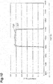
- FIG. 10 illustrates a temporal waveform G21 of the output light Ld corresponding to the plot P1 and a desired waveform G23 given as the initial target waveform Target 0 (t)
- FIG. 11 illustrates a temporal waveform G22 of the output light Ld corresponding to the plot P2 and the desired waveform G23 given as the initial target waveform Target 0 (t).
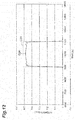
- FIG 12 illustrates a temporal waveform G24 of the output light Ld corresponding to the plot P3 and the desired waveform G23 given as the initial target waveform Target 0 (t)
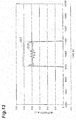
- FIG. 13 illustrates a temporal waveform G25 of the output light Ld corresponding to the plot P4 and the desired waveform G23 given as the initial target waveform Target 0 (t).
- FIG. 14 is another graph illustrating the intensity loss and the waveform accuracy with the waveform control.
- a plot P5 in the drawing shows the case in which modulation based on the phase spectrum function ⁇ IFTA ( ⁇ ) obtained without introducing the coefficient ⁇ and the intensity spectrum function A IFTA ( ⁇ ) obtained by introducing the coefficient ⁇ is performed. Further, a plot P6 shows the case in which modulation based on both the phase spectrum function ⁇ IFTA ( ⁇ ) and the intensity spectrum function A IFTA ( ⁇ ) obtained without introducing the coefficient ⁇ is performed.
- the modulation pattern calculation apparatus, the light control apparatus, the modulation pattern calculation method, and the modulation pattern calculation program according to one aspect of the present invention are not limited to the embodiments and the modifications described above, and various other modifications are enabled.
- the coefficient ⁇ is applied to IFTA-Fienup (second comparative example)
- the present invention is not limited thereto, and for example, the coefficient ⁇ may be applied to the normal iterative Fourier method according to the first comparative example.
- the coefficient ⁇ in which the difference between the waveform function after the Fourier transform and the result of multiplying the function representing the desired waveform by the coefficient ⁇ decreases is calculated by minimizing the standard deviation ⁇ .
- the calculation method of the coefficient ⁇ is not limited thereto, and for example, a total sum (that is, a time integral value) of difference values between the waveform function after the Fourier transform and the result of multiplying the function representing the desired waveform by the coefficient ⁇ may be minimized.
- the modulation pattern calculation apparatus is an apparatus for calculating a modulation pattern presented on a spatial light modulator for modulating at least one of an intensity spectrum and a phase spectrum of input light to bring a temporal intensity waveform of light close to a desired waveform
- the apparatus includes an iterative Fourier transform unit for performing a Fourier transform on a waveform function in a frequency domain including an intensity spectrum function and a phase spectrum function, performing a first replacement of a temporal intensity waveform function based on the desired waveform in a time domain after the Fourier transform and then performing an inverse Fourier transform, and performing a second replacement to constrain one spectrum function of the intensity spectrum function and the phase spectrum function in the frequency domain after the inverse Fourier transform, and a modulation pattern calculation unit for calculating the modulation pattern on the basis of the other spectrum function output from the iterative Fourier transform unit.
- the iterative Fourier transform unit performs the first replacement using a result of multiplying a function representing the desired waveform by a coefficient.
- the coefficient has a value in which a difference between the function after the multiplication and the temporal intensity waveform function after the Fourier transform is smaller than a difference before the multiplication of the coefficient.
- the modulation pattern calculation method is a method for calculating a modulation pattern presented on a spatial light modulator for modulating at least one of an intensity spectrum and a phase spectrum of input light to bring a temporal intensity waveform of light close to a desired waveform
- the method includes an iterative Fourier transform step of performing a Fourier transform on a waveform function in a frequency domain including an intensity spectrum function and a phase spectrum function, performing a first replacement of a temporal intensity waveform function based on the desired waveform in a time domain after the Fourier transform and then performing an inverse Fourier transform, and performing a second replacement to constrain one spectrum function of the intensity spectrum function and the phase spectrum function in the frequency domain after the inverse Fourier transform, and a modulation pattern calculation step of calculating the modulation pattern on the basis of the other spectrum function output in the iterative Fourier transform step.
- the first replacement is performed using a result of multiplying a function representing the desired waveform by a coefficient.
- the coefficient has a value in which a difference between the function after the multiplication and the temporal intensity waveform function after the Fourier transform is smaller than a difference before the multiplication of the coefficient.
- the modulation pattern calculation program operates a computer, in an apparatus for calculating a modulation pattern presented on a spatial light modulator for modulating at least one of an intensity spectrum and a phase spectrum of input light to bring a temporal intensity waveform of light close to a desired waveform, as an iterative Fourier transform unit for performing a Fourier transform on a waveform function in a frequency domain including an intensity spectrum function and a phase spectrum function, performing a first replacement of a temporal intensity waveform function based on the desired waveform in a time domain after the Fourier transform and then performing an inverse Fourier transform, and performing a second replacement to constrain one spectrum function of the intensity spectrum function and the phase spectrum function in the frequency domain after the inverse Fourier transform, and a modulation pattern calculation unit for calculating the modulation pattern on the basis of the other spectrum function output from the iterative Fourier transform unit.
- the iterative Fourier transform unit operates such that the first replacement is performed using a result of multiplying a function representing the desired waveform by a coefficient.
- the coefficient has a value in which a difference between the function after the multiplication and the temporal intensity waveform function after the Fourier transform is smaller than a difference before the multiplication of the coefficient.
- the iterative Fourier transform unit may repeatedly perform the Fourier transform, the first replacement, the inverse Fourier transform, and the second replacement, and in the modulation pattern calculation step, the modulation pattern calculation unit may calculate the modulation pattern on the basis of the other spectrum function obtained after the repetition. As such, the iterative Fourier transform is repeatedly performed, so that the intensity spectrum or the phase spectrum to bring the temporal intensity waveform of the light close to the desired waveform can be calculated more accurately.
- the coefficient may have the value in which a standard deviation of the function after the multiplication with respect to the temporal intensity waveform function after the Fourier transform is minimized.
- the light control apparatus includes the modulation pattern calculation apparatus described above, a light source for outputting the input light, a dispersive element for spectrally dispersing the input light, a spatial light modulator for modulating at least one of an intensity spectrum and a phase spectrum of the input light after the dispersion and outputting modulated light, and an optical system for focusing the modulated light.
- the spatial light modulator presents the modulation pattern calculated by the above modulation pattern calculation apparatus.
- the modulation pattern calculation apparatus described above is included, so that the solution can be prevented from being led to the local solution during an iterative Fourier operation, and the intensity spectrum or the phase spectrum to bring the temporal waveform of the light close to the desired waveform can be accurately calculated.
- the present invention can be used as a modulation pattern calculation apparatus, a light control apparatus, a modulation pattern calculation method, a modulation pattern calculation program, and a computer readable medium capable of preventing a solution from being led to a local solution during an iterative Fourier operation, and accurately calculating an intensity spectrum or a phase spectrum to bring a temporal waveform of light close to a desired waveform.
- 1A - light control apparatus 2 - light source, 10 - optical system, 12 - dispersive element, 14 - curved mirror, 16 - spatial light modulator (SLM), 17 - modulation plane, 20 - modulation pattern calculation apparatus, 21 - arbitrary waveform input unit, 22 - phase spectrum design unit, 22a - iterative Fourier transform unit, 23 - intensity spectrum design unit, 23a - iterative Fourier transform unit, 24 - modulation pattern calculation unit, La - input light, Ld - output light.
- SLM spatial light modulator
Landscapes
- Physics & Mathematics (AREA)
- Nonlinear Science (AREA)
- General Physics & Mathematics (AREA)
- Engineering & Computer Science (AREA)
- Optics & Photonics (AREA)
- Mathematical Physics (AREA)
- Crystallography & Structural Chemistry (AREA)
- Chemical & Material Sciences (AREA)
- Pure & Applied Mathematics (AREA)
- General Engineering & Computer Science (AREA)
- Mathematical Analysis (AREA)
- Electromagnetism (AREA)
- Data Mining & Analysis (AREA)
- Computational Mathematics (AREA)
- Theoretical Computer Science (AREA)
- Mathematical Optimization (AREA)
- Software Systems (AREA)
- Databases & Information Systems (AREA)
- Plasma & Fusion (AREA)
- Algebra (AREA)
- Automation & Control Theory (AREA)
- Optical Modulation, Optical Deflection, Nonlinear Optics, Optical Demodulation, Optical Logic Elements (AREA)
- Liquid Crystal (AREA)
Abstract
Description
- An aspect of the present invention relates to a modulation pattern calculation apparatus, a light control apparatus, a modulation pattern calculation method, a modulation pattern calculation program, and a computer readable medium.
-
Non Patent Document 1 discloses technology for modulating a phase spectrum using a spatial light modulator (SLM) to shape a light pulse. In this document, a phase spectrum to obtain a desired light pulse waveform is calculated using an iterative Fourier method (iterative Fourier transform algorithm: IFTA). Further,Non Patent Document 2 discloses an iterative Fourier method modified to avoid a solution from being led to a local solution, in phase spectrum modulation to shape a light pulse. -
- Non Patent Document 1: M. Hacker, G Stobrawa, T. Feurer, "Iterative Fourier transform algorithm for phase-only pulse shaping", Optics Express, Vol. 9, No. 4, pp. 191-199, 13 August 2001
- Non Patent Document 2: Olivier Ripoll, Ville Kettunen, Hans Peter Herzig, "Review of iterative Fourier-transform algorithms for beam shaping applications", Optical Engineering, Vol. 43, No. 11, pp. 2549-2556, November 2004
- For example, as technology for controlling a temporal waveform of a variety of light such as ultrashort pulse light, technology for modulating a phase spectrum and an intensity spectrum of a light pulse by the SLM is known. In this technology, a modulation pattern to give, to the light, a phase spectrum and an intensity spectrum (or one of them) to bring the temporal waveform of the light close to a desired waveform is presented on the SLM. In this case, to easily realize an arbitrary temporal waveform, it is desirable to obtain these spectra by calculation.
- When these spectra are obtained by the calculation, the iterative Fourier method is used as described in
Non Patent Document 1, for example. However, in the iterative Fourier method, there is a problem in that a solution may be led to a local solution, and an optimal solution is not necessarily obtained. In view of the problem, inNon Patent Document 2, a difference between a desired waveform and a waveform after a Fourier transform is multiplied by a predetermined coefficient, a result is added to the desired waveform, and an iterative Fourier operation is performed. However, even in this method, for example, when the desired waveform and the waveform after the Fourier transform are greatly different from each other, the solution may be led to the local solution. - An object of one aspect of the present invention is to provide a modulation pattern calculation apparatus, a light control apparatus, a modulation pattern calculation method, a modulation pattern calculation program, and a computer readable medium capable of preventing a solution from being led to a local solution during an iterative Fourier operation and accurately calculating an intensity spectrum or a phase spectrum to bring a temporal waveform of light close to a desired waveform.
- In order to solve the above problem, a modulation pattern calculation apparatus according to one aspect of the present invention is an apparatus for calculating a modulation pattern presented on a spatial light modulator for modulating at least one of an intensity spectrum and a phase spectrum of input light to bring a temporal intensity waveform of light close to a desired waveform, and the apparatus includes an iterative Fourier transform unit for performing a Fourier transform on a waveform function in a frequency domain including an intensity spectrum function and a phase spectrum function, performing a first replacement of a temporal intensity waveform function based on the desired waveform in a time domain after the Fourier transform and then performing an inverse Fourier transform, and performing a second replacement to constrain one spectrum function of the intensity spectrum function and the phase spectrum function in the frequency domain after the inverse Fourier transform, and a modulation pattern calculation unit for calculating the modulation pattern on the basis of the other spectrum function output from the iterative Fourier transform unit. The iterative Fourier transform unit performs the first replacement using a result of multiplying a function representing the desired waveform by a coefficient. The coefficient has a value in which a difference between the function after the multiplication and the temporal intensity waveform function after the Fourier transform is smaller than a difference before the multiplication of the coefficient.
- Further, a modulation pattern calculation method according to one aspect of the present invention is a method for calculating a modulation pattern presented on a spatial light modulator for modulating at least one of an intensity spectrum and a phase spectrum of input light to bring a temporal intensity waveform of light close to a desired waveform, and the method includes a step (Fourier transform step) of performing a Fourier transform on a waveform function in a frequency domain including an intensity spectrum function and a phase spectrum function, a step (inverse Fourier transform step) of performing a first replacement of a temporal intensity waveform function based on the desired waveform in a time domain after the Fourier transform and then performing an inverse Fourier transform, a step (replacement step) of performing a second replacement to constrain one spectrum function of the intensity spectrum function and the phase spectrum function in the frequency domain after the inverse Fourier transform, and a step (modulation pattern calculation step) of calculating the modulation pattern on the basis of the other spectrum function output in the step of performing the second replacement. In the step of performing the inverse Fourier transform, the first replacement is performed using a result of multiplying a function representing the desired waveform by a coefficient. The coefficient has a value in which a difference between the function after the multiplication and the temporal intensity waveform function after the Fourier transform is smaller than a difference before the multiplication of the coefficient.
- Further, a modulation pattern calculation program according to one aspect of the present invention is a program for causing a computer to calculate a modulation pattern presented on a spatial light modulator for modulating at least one of an intensity spectrum and a phase spectrum of input light to bring a temporal intensity waveform of light close to a desired waveform, and the program causes the computer to execute a step (Fourier transform step) of performing a Fourier transform on a waveform function in a frequency domain including an intensity spectrum function and a phase spectrum function, a step (inverse Fourier transform step) of performing a first replacement of a temporal intensity waveform function based on the desired waveform in a time domain after the Fourier transform and then performing an inverse Fourier transform, a step (replacement step) of performing a second replacement to constrain one spectrum function of the intensity spectrum function and the phase spectrum function in the frequency domain after the inverse Fourier transform, and a step (modulation pattern calculation step) of calculating the modulation pattern on the basis of the other spectrum function output in the step of performing the second replacement. In the step of performing the inverse Fourier transform, the first replacement is performed using a result of multiplying a function representing the desired waveform by a coefficient. The coefficient has a value in which a difference between the function after the multiplication and the temporal intensity waveform function after the Fourier transform is smaller than a difference before the multiplication of the coefficient.
- In the above apparatus, the method, and the program, the intensity spectrum or the phase spectrum to bring the temporal intensity waveform of the light close to the desired waveform is calculated in the iterative Fourier transform unit or the replacement step. At that time, as described above, in a normal iterative Fourier method, a solution may be led to a local solution and an optimal solution is not necessarily obtained. Therefore, in the above apparatus and the method, when the replacement based on the desired waveform is performed on the temporal intensity waveform function in the time domain obtained by the Fourier transform, the result of multiplying the function representing the desired waveform by the coefficient is used. The coefficient has the value in which the difference between the function after the multiplication and the temporal intensity waveform function after the Fourier transform is smaller than the difference before the multiplication of the coefficient. As a result, because a difference between the function before the replacement (that is, the temporal intensity waveform function after the Fourier transform) and the function after the replacement based on the desired waveform decreases, the solution is prevented from being led to the local solution. Therefore, according to the above apparatus and the method, the intensity spectrum or the phase spectrum to bring the temporal waveform of the light close to the desired waveform can be accurately calculated.
- Further, a light control apparatus according to one aspect of the present invention includes the modulation pattern calculation apparatus having the above configuration, a light source for outputting the input light, a dispersive element for spectrally dispersing the input light, a spatial light modulator for modulating at least one of an intensity spectrum and a phase spectrum of the input light after the dispersion and outputting modulated light, and an optical system for focusing the modulated light. The spatial light modulator presents the modulation pattern calculated by the modulation pattern calculation apparatus.
- According to this apparatus, the modulation pattern calculation apparatus having the above configuration is included, so that the solution can be prevented from being led to the local solution during an iterative Fourier operation and the intensity spectrum or the phase spectrum to bring the temporal waveform of the light close to the desired waveform can be accurately calculated.
- According to a modulation pattern calculation apparatus, a light control apparatus, a modulation pattern calculation method, a modulation pattern calculation program, and a computer readable medium according to one aspect of the present invention, a solution can be prevented from being led to a local solution during an iterative Fourier operation, and an intensity spectrum or a phase spectrum to bring a temporal waveform of light close to a desired waveform can be accurately calculated.
-
- [
FIG. 1] FIG. 1 is a diagram schematically illustrating a configuration of a light control apparatus according to an embodiment. - [
FIG. 2] FIG. 2 is a diagram illustrating a modulation plane of an SLM. - [
FIG. 3] FIG. 3 includes (a) a graph illustrating an example of a combination of a certain phase spectrum and a certain intensity spectrum, and (b) a graph illustrating a temporal intensity waveform of output light realized by the combination of the phase spectrum and the intensity spectrum illustrated in (a) inFIG. 3 . - [
FIG. 4] FIG. 4 is a diagram illustrating a calculation procedure of a phase spectrum using a normal iterative Fourier method, as a first comparative example. - [
FIG. 5] FIG. 5 is a diagram illustrating a calculation procedure of a phase spectrum using an iterative Fourier method described inNon Patent Document 2, as a second comparative example. - [
FIG. 6] FIG. 6 is a diagram illustrating a calculation procedure of a phase spectrum using an improved iterative Fourier method in an embodiment. - [
FIG. 7] FIG. 7 is a diagram illustrating a calculation procedure in an iterative Fourier transform unit of an intensity spectrum design unit. - [
FIG. 8] FIG. 8 is a flowchart illustrating a modulation pattern calculation method. - [
FIG. 9] FIG. 9 is a graph illustrating intensity loss and waveform accuracy with waveform control. - [
FIG. 10] FIG. 10 is a diagram illustrating a temporal waveform of output light and a desired waveform. - [
FIG. 11] FIG. 11 is a diagram illustrating a temporal waveform of output light and a desired waveform. - [
FIG. 12] FIG. 12 is a diagram illustrating a temporal waveform of output light and a desired waveform. - [
FIG. 13] FIG. 13 is a diagram illustrating a temporal waveform of output light and a desired waveform. - [
FIG. 14] FIG. 14 is a graph illustrating intensity loss and waveform accuracy with waveform control. - Hereinafter, embodiments of a modulation pattern calculation apparatus, a light control apparatus, a modulation pattern calculation method, and a modulation pattern calculation program according to one aspect of the present invention will be described in detail with reference to the accompanying drawings. In the description of the drawings, the same elements will be denoted by the same reference signs, without redundant description.
-
FIG. 1 is a diagram schematically illustrating a configuration of alight control apparatus 1A according to an embodiment of the present invention. Thelight control apparatus 1A according to the present embodiment generates, from input light La, output light Ld having an arbitrary temporal intensity waveform different from that of the input light La. As illustrated inFIG. 1 , thelight control apparatus 1A includes alight source 2, anoptical system 10, and a modulationpattern calculation apparatus 20. - The
light source 2 outputs the input light La input to theoptical system 10. Thelight source 2 is a laser light source such as a solid-state laser light source, for example, and the input light La is coherent pulse light, for example. - The
optical system 10 has adispersive element 12, acurved mirror 14, and anSLM 16. Thedispersive element 12 is optically coupled to thelight source 2, and the SLM 16 is optically coupled to thedispersive element 12 via thecurved mirror 14. Thedispersive element 12 spectrally disperses the input light La for each wavelength component. Thedispersive element 12 has a diffraction grating formed on a plate surface, for example. Further, thedispersive element 12 may have a prism. The input light La is obliquely incident on the diffraction grating, and is spectrally dispersed into a plurality of wavelength components. Light Lb including the plurality of wavelength components reaches thecurved mirror 14. The light Lb is reflected by thecurved mirror 14 and reaches theSLM 16. - The
SLM 16 simultaneously performs phase modulation and intensity modulation of the light Lb to generate the output light Ld having an arbitrary temporal intensity waveform different from the waveform of the input light La. TheSLM 16 is of a phase modulation type, for example. In one example, theSLM 16 is of an LCOS (liquid crystal on silicon) type. -
FIG. 2 is a diagram illustrating amodulation plane 17 of theSLM 16. As illustrated inFIG. 2 , in themodulation plane 17, a plurality ofmodulation regions 17a are arranged along a certain direction A, and eachmodulation region 17a extends in a direction B intersecting with the direction A. The direction A is a dispersing direction by thedispersive element 12. Therefore, each of the spectrally dispersed wavelength components is incident on each of the plurality ofmodulation regions 17a. TheSLM 16 modulates a phase and an intensity of each incident wavelength component in eachmodulation region 17a. Because theSLM 16 in the present embodiment is of the phase modulation type, the intensity modulation is realized by a phase pattern (phase image) presented on themodulation plane 17. - Modulated light Lc including the respective wavelength components modulated by the
SLM 16 is reflected again by thecurved mirror 14 and reaches thedispersive element 12. At this time, thecurved mirror 14 functions as a focusing optical system for focusing the modulated light Lc. Further, thedispersive element 12 functions as a combining optical system and combines the respective wavelength components after the modulation. That is, by thecurved mirror 14 and thedispersive element 12, the plurality of wavelength components of the modulated light Lc are focused and combined with each other and become the output light Ld. The output light Ld is light having a desired temporal intensity waveform different from the waveform of the input light La. - The modulation
pattern calculation apparatus 20 is a computer having an operation circuit such as a processor. The modulationpattern calculation apparatus 20 is electrically coupled to theSLM 16, calculates a phase modulation pattern to bring the temporal intensity waveform of the output light Ld close to a desired waveform, and provides a control signal including the phase modulation pattern to theSLM 16. - The modulation
pattern calculation apparatus 20 of the present embodiment presents, on theSLM 16, a phase pattern including a phase pattern for phase modulation that gives a phase spectrum for obtaining the desired waveform to the output light Ld and a phase pattern for intensity modulation that gives an intensity spectrum for obtaining the desired waveform to the output light Ld. For this purpose, the modulationpattern calculation apparatus 20 includes an arbitrarywaveform input unit 21, a phasespectrum design unit 22, an intensityspectrum design unit 23, and a modulationpattern calculation unit 24. That is, the operation circuit (for example, the processor of the computer) provided in the modulationpattern calculation apparatus 20 realizes a function of the arbitrarywaveform input unit 21, a function of the phasespectrum design unit 22, a function of the intensityspectrum design unit 23, and a function of the modulationpattern calculation unit 24. The respective functions may be realized by the same operation circuit or may be realized by different operation circuits. - The operation circuit (for example, the processor of the computer) can realize the above respective functions by a modulation pattern calculation program. Therefore, the modulation pattern calculation program operates the operation circuit (for example, the processor of the computer) as the arbitrary
waveform input unit 21, the phasespectrum design unit 22, the intensityspectrum design unit 23, and the modulationpattern calculation unit 24 in the modulationpattern calculation apparatus 20. The modulation pattern calculation program is stored in a storage device (non-transitory computer readable medium) inside or outside the computer. - The arbitrary
waveform input unit 21 receives the desired temporal intensity waveform input from an operator. The operator inputs information (for example, a pulse width) on the desired temporal intensity waveform to the arbitrarywaveform input unit 21. - The information on the desired temporal intensity waveform is given to the phase
spectrum design unit 22 and the intensityspectrum design unit 23. The phasespectrum design unit 22 calculates a corresponding phase spectrum of the output light Ld, on the basis of the temporal intensity waveform. The intensityspectrum design unit 23 calculates a corresponding intensity spectrum of the output light Ld, on the basis of the temporal intensity waveform. - The modulation
pattern calculation unit 24 is an example of a modulation pattern calculation unit according to one aspect of the present invention and calculates a phase modulation pattern to give the phase spectrum obtained in the phasespectrum design unit 22 and the intensity spectrum obtained in the intensityspectrum design unit 23 to the output light Ld. Further, a control signal including the calculated phase modulation pattern is provided to theSLM 16. - Here, a method of calculating a phase spectrum and an intensity spectrum corresponding to a desired temporal intensity waveform is described in detail. (a) in
FIG. 3 is a graph illustrating an example of a combination of a certain phase spectrum G11 and a certain intensity spectrum G12. Further, (b) inFIG. 3 is a graph illustrating a temporal intensity waveform of the output light Ld realized by the combination of the phase spectrum and the intensity spectrum illustrated in (a) inFIG. 3 . In (a) inFIG. 3 , a horizontal axis shows a wavelength (nm), a left vertical axis shows an intensity value (arbitrary unit) of the intensity spectrum, and a right vertical axis shows a phase value (rad) of the phase spectrum. Further, in (b) inFIG. 3 , a horizontal axis shows a time (femtosecond) and a vertical axis shows a light intensity (arbitrary unit). The spectra and the waveform illustrated inFIG. 3 are examples, and the temporal intensity waveform of the output light Ld can be controlled in various forms by combinations of various phase spectra and intensity spectra. - The desired temporal intensity waveform is represented as a function in a time domain, and the phase spectrum and the intensity spectrum are represented as functions in a frequency domain. Therefore, the phase spectrum and the intensity spectrum corresponding to the desired temporal intensity waveform are obtained by an iterative Fourier transform based on the desired temporal intensity waveform. In the method described below, the phase spectrum and the intensity spectrum are calculated using an iterative Fourier transform method. Therefore, as illustrated in
FIG. 1 , the phasespectrum design unit 22 has an iterativeFourier transform unit 22a. Further, the intensityspectrum design unit 23 has an iterativeFourier transform unit 23a. - However, in a normal iterative Fourier method, as described above, a solution may be led to a local solution and an optimal solution is not necessarily obtained. Further, there are problems in that it takes long time to converge calculation (that is, the number of iterations increases) and intensity loss increases.
FIG. 4 illustrates a calculation procedure of a phase spectrum using the normal iterative Fourier method, as a first comparative example for the present embodiment. - First, an initial intensity spectrum function A0(ω) and a phase spectrum function Ψn=0(ω) to be functions of a frequency ω are prepared (process number (1) in the drawing). In one example, the intensity spectrum function A0(ω) and the phase spectrum function Ψn=0(ω) represent the intensity spectrum and the phase spectrum of the input light La, respectively. Next, a waveform function (a) in the frequency domain including the intensity spectrum function A0(ω) and the phase spectrum function Ψn(ω) is prepared (process number (2) in the drawing).
[Formula 1]
- Next, a Fourier transform from the frequency domain to the time domain is performed on the function (a) (arrow A1 in the drawing). As a result, a waveform function (b) in the frequency domain including a temporal intensity waveform function bn(t) is obtained (process number (3) in the drawing).
[Formula 2]
- Next, the temporal intensity waveform function bn(t) included in the function (b) is replaced by Target0(t) based on the desired waveform (process numbers (4) and (5) in the drawing).
[Formula 3]

- Next, an inverse Fourier transform from the time domain to the frequency domain is performed on the function (d) (arrow A2 in the drawing). As a result, a waveform function (e) in the frequency domain including an intensity spectrum function Bn(ω) and the phase spectrum function Ψn(ω)is obtained (process number (6) in the drawing).
[Formula 5]
- Next, to constrain the intensity spectrum function Bn(ω) included in the function (e), this is replaced by the initial intensity spectrum function A0(ω) (process number (7) in the drawing).
[Formula 6]
- Subsequently, the above processes (1) to (7) are repeatedly performed a plurality of times, so that the phase spectrum form represented by the phase spectrum function Ψn(ω) in the waveform function can be brought close to a phase spectrum form corresponding to the desired temporal intensity waveform. A phase spectrum function ΨIFTA(ω) to be finally obtained is used to calculate the modulation pattern.
- For the normal iterative Fourier method described above, a process for preventing a solution from being led to a local solution is included in a method described in
Non Patent Document 2.FIG. 5 illustrates a calculation procedure of a phase spectrum using an iterative Fourier method (hereinafter, referred to as IFTA-Fienup) described inNon Patent Document 2, as a second comparative example for the present embodiment. Here, inFIG. 5 , because processes (1) to (3), (6) to (7) are the same as the processes in the above-described method, explanation is omitted. - In IFTA-Fienup, when processes (4) and (5) are executed, that is, a replacement based on a desired waveform is performed on the temporal intensity waveform function bn(t) included in the function (b) after the Fourier transform, instead of Target0(t), Targetn(t) calculated by the following formula (g) is used (process numbers (4) and (5) in the drawing).
[Formula 7]

- Here, in the above formula (g), a difference (Target0(t) - bn(t)) between the function Target0(t) representing the desired waveform and the waveform function bn(t) after the Fourier transform is multiplied by a predetermined coefficient β, a multiplication result is added to the desired waveform Target0(t), and Targetn(t) is calculated. Further, when this value is smaller than 0, Targetn(t) = 0 is set.
- However, even in IFTA-Fienup, for example, when the function Target0(t) representing the desired waveform and the waveform function bn(t) after the Fourier transform are greatly different from each other, a solution may still be led to a local solution.
- Therefore, in the iterative
Fourier transform unit 22a of the phasespectrum design unit 22 in the present embodiment, the iterative Fourier method is further improved as described below.FIG. 6 illustrates a calculation procedure of a phase spectrum using the improved iterative Fourier method in the present embodiment. - First, the iterative
Fourier transform unit 22a prepares the initial intensity spectrum function A0(ω) and the phase spectrum function Ψn=0(ω) to be the functions of the frequency ω (process number (1) in the drawing). In one example, the intensity spectrum function A0(ω) and the phase spectrum function Ψn=0(ω) represent the intensity spectrum and the phase spectrum of the input light La, respectively. - Next, the iterative
Fourier transform unit 22a prepares a waveform function (i) in the frequency domain including the intensity spectrum function A0(ω) and the phase spectrum function Ψn(ω) (process number (2) in the drawing).
[Formula 9]
- Next, the iterative
Fourier transform unit 22a performs the Fourier transform from the frequency domain to the time domain on the function (i). As a result, a waveform function (j) in the frequency domain including the temporal intensity waveform function bn(t) is obtained (process number (3) in the drawing).
[Formula 10]
- Next, the iterative
Fourier transform unit 22a calculates a coefficient α in which a difference between the waveform function bn(t) after the Fourier transform and a result (α × Target0(t)) of multiplying the function Target0(t) by the coefficient α becomes smaller than a difference between the waveform function bn(t) and the function Target0(t) (process number (4) in the drawing). In one example, as shown by the following formula (k), a coefficient α in which a standard deviation σ of α × Target0(t) with respect to the waveform function bn(t) after the Fourier transform becomes a minimum (σmin) is derived by searching. Here, in the formula (k), D represents the number of data points and ts and te represent a start point and an end point of a time axis, respectively.
[Formula 11]
- Next, the iterative
Fourier transform unit 22a performs a replacement based on the desired waveform on the temporal intensity waveform function bn(t) included in the function (j) after the Fourier transform (first replacement). At this time, the iterativeFourier transform unit 22a performs the replacement using the result (α × Target0(t)) of multiplying the function Target0(t) representing the desired waveform by the coefficient α. In one example, the replacement is performed by Targetn(t) calculated by the formula (m) obtained by replacing Target0(t) in the formula (g) in IFTA-Fienup described above by α × Target0(t) (process numbers (5) and (6) in the drawing).
[Formula 12]

- Next, the iterative
Fourier transform unit 22a performs the inverse Fourier transform from the time domain to the frequency domain on the function (n) (arrow A2 in the drawing). As a result, a waveform function (o) in the frequency domain including the intensity spectrum function Bn(ω) and the phase spectrum function Ψn(ω) is obtained (process number (7) in the drawing).
[Formula 14]
- Next, the iterative
Fourier transform unit 22a, to constrain the intensity spectrum function Bn(ω) included in the function (o), replaces the function by the initial intensity spectrum function A0(ω) (second replacement, process number (8) in the drawing).
[Formula 15]
- Subsequently, the iterative
Fourier transform unit 22a repeatedly performs the above processes (1) to (8) a plurality of times, so that the phase spectrum form represented by the phase spectrum function Ψn(ω) in the waveform function can be brought close to a phase spectrum form corresponding to the desired temporal intensity waveform. A phase spectrum function ΨIFTA(ω) to be finally obtained is provided to the modulationpattern calculation unit 24. -
FIG. 7 illustrates a calculation procedure in the iterativeFourier transform unit 23a of the intensityspectrum design unit 23. The iterativeFourier transform unit 23a calculates an intensity spectrum by the similar method as the calculation method by the iterativeFourier transform unit 22a described above. - First, similar to when the phase spectrum is calculated, the iterative
Fourier transform unit 23a prepares an initial intensity spectrum function Ak=0(ω) and a phase spectrum function Ψ0(ω) (process number (1) in the drawing). Next, the iterativeFourier transform unit 23a prepares a waveform function (q) in the frequency domain including an intensity spectrum function Ak(ω) and the phase spectrum function Ψ0(ω) (process number (2) in the drawing).
[Formula 16]
- Next, the iterative
Fourier transform unit 23a performs the Fourier transform from the frequency domain to the time domain on the function (q). As a result, a waveform function (r) in the frequency domain including a temporal intensity waveform function bk(t) is obtained (process number (3) in the drawing).
[Formula 17]
- Next, the iterative
Fourier transform unit 23a calculates a coefficient α in which a difference between the waveform function bk(t) after the Fourier transform and a result (α × Target0(t)) of multiplying the function Target0(t) by the coefficient α becomes smaller than a difference between the waveform function bk(t) and the function Target0(t) (process number (4) in the drawing). In one example, as shown by the following formula (s), a coefficient α in which a standard deviation σ of α × Target0(t) with respect to the waveform function bk(t) after the Fourier transform becomes a minimum (σmin) is derived by searching. Here, in the formula (s), D represents the number of data points and ts and te represent a start point and an end point of a time axis, respectively.
[Formula 18]
- Next, the iterative
Fourier transform unit 23a performs a replacement based on the desired waveform on the temporal intensity waveform function bk(t) included in the function (r) after the Fourier transform (first replacement). At this time, the iterativeFourier transform unit 23a performs the replacement using the result (α × Target0(t)) of multiplying the function Target0(t) representing the desired waveform by the coefficient a. In one example, the replacement is performed by Targetk(t) calculated by the formula (t) (process numbers (5) and (6) in the drawing).
[Formula 19]

- Next, the iterative
Fourier transform unit 23a performs the inverse Fourier transform from the time domain to the frequency domain on the function (u). As a result, a waveform function (v) in the frequency domain including an intensity spectrum function Ck(ω) and a phase spectrum function Ψk(ω) is obtained (process number (7) in the drawing).
[Formula 21]
Fourier transform unit 23a, to constrain the phase spectrum function Ψk(ω) included in the function (v), replaces the function by the initial phase spectrum function Ψ0(ω) (second replacement, process number (8) in the drawing).
[Formula 22]
- Subsequently, the iterative
Fourier transform unit 23a repeatedly performs the above processes (1) to (8) a plurality of times, so that the phase spectrum form represented by the intensity spectrum function Ak(ω) in the waveform function can be brought close to an intensity spectrum form corresponding to the desired temporal intensity waveform. An intensity spectrum function AIFTA(ω) to be finally obtained is provided to the modulationpattern calculation unit 24. -
FIG. 8 is a flowchart illustrating a modulation pattern calculation method realized by the modulationpattern calculation apparatus 20 described above. As illustrated inFIG 8 , first, information on a desired temporal intensity waveform is input to the arbitrarywaveform input unit 21 by the operator (input step S1). Next, a phase spectrum and an intensity spectrum to bring the temporal intensity waveform close to a desired waveform are calculated in the phasespectrum design unit 22 and the intensityspectrum design unit 23, respectively (phase spectrum calculation step S11 and intensity spectrum calculation step S21). - An iterative Fourier transform step S12 by the iterative
Fourier transform unit 22a is included in the phase spectrum calculation step S11. - That is, in the iterative Fourier transform step S12, the Fourier transform is performed on the waveform function (formula (i)) in the frequency domain including the intensity spectrum function A0(ω) and the phase spectrum function Ψn(ω), the replacement of the temporal intensity waveform function based on the desired waveform is performed in the time domain after the Fourier transform (formulas (m) and (n)), and the replacement to constrain the intensity spectrum function is performed in the frequency domain after the inverse Fourier transform (formula (p)). In the iterative Fourier transform step S12, these processes are repeatedly performed a plurality of times, so that the phase spectrum function Ψn(ω) is brought close to a phase spectrum form corresponding to the desired waveform. A phase spectrum function ΨIFTA(ω) to be finally obtained is provided to a next modulation pattern calculation step S3.
- Further, an iterative Fourier transform step S22 by the iterative
Fourier transform unit 23a is included in the intensity spectrum calculation step S21. - That is, in the iterative Fourier transform step S22, the Fourier transform is performed on the waveform function (formula (q)) in the frequency domain including the intensity spectrum function Ak(ω) and the phase spectrum function Ψ0(ω), the replacement of the temporal intensity waveform function based on the desired waveform is performed in the time domain after the Fourier transform (formulas (t) and (u)), and the replacement to constrain the phase spectrum function is performed in the frequency domain after the inverse Fourier transform (formula (w)). In the iterative Fourier transform step S22, these processes are repeatedly performed a plurality of times, so that the intensity spectrum function Ak(ω) is brought close to an intensity spectrum form corresponding to the desired waveform. An intensity spectrum function AIFTA(ω) to be finally obtained is provided to the next modulation pattern calculation step S3.
- In the modulation pattern calculation step S3, a modulation pattern is calculated on the basis of the phase spectrum function ΨIFTA(ω) and the intensity spectrum function ΨIFTA(ω). The modulation pattern is presented on the
SLM 16. - Effects obtained by the modulation
pattern calculation apparatus 20 and the modulation pattern calculation method according to the present embodiment described above are described. - In the present embodiment, the intensity spectrum and the phase spectrum to bring the temporal intensity waveform of the light close to the desired waveform are calculated in the iterative
Fourier transform units - In particular, when the intensity spectrum function AIFTA(ω) is derived by the iterative Fourier method , the intensity spectrum after the inverse Fourier transform may exceed the intensity spectrum of the input light La depending on a wavelength region. In this case, because realization is impossible for a part exceeding the intensity spectrum of the input light La, intensity loss occurs with the iterative calculation and the intensity of the temporal intensity waveform bn(t) gradually decreases. Therefore, in the conventional iterative Fourier method, a difference between the waveform Target0(t) after the replacement and the temporal intensity waveform bn(t) (or bk(t)) tends to increase and a risk of the solution being led to the local solution increases. On the other hand, according to the present embodiment, because a difference between the waveform function Targetn(t) (or Targetk(t)) after the replacement and the temporal intensity waveform bn(t) (or bk(t)) can be decreased, it is possible to reduce the risk of the solution being led to the local solution while suppressing the intensity loss.
- Further, as in the present embodiment, the iterative
Fourier transform units - Further, as in the present embodiment, the coefficient α may have a value in which the standard deviation σ of the function α × Target0(t) after the multiplication with respect to the temporal intensity waveform function bn(t) (or bk(t)) after the Fourier transform becomes a minimum value σmin. As a result, a difference between the function α × Target0(t) after the multiplication of the coefficient α and the temporal intensity waveform function bn(t) (or bk(t)) after the Fourier transform can be minimized, and the solution can be more effectively prevented from being led to the local solution.
- Here, in the above embodiment, both the phase spectrum function ΨIFTA(ω) and the intensity spectrum function ΨIFTA(ω) are calculated to bring the temporal intensity waveform close to the desired waveform, and the modulation pattern based on these functions is presented on the
SLM 16. However, the present invention is not limited to such a configuration, and for example, only one of the phase spectrum function ΨIFTA(ω) and the intensity spectrum function AIFTA to bring the temporal intensity waveform close to the desired waveform may be calculated. In this case, a previously prepared (or selected) spectrum may be used as the other spectrum, or the other spectrum may not be modulated as the input light La. Even in any configuration, the effects according to the present embodiment can be surely obtained. -
FIG. 9 is a graph illustrating intensity loss and waveform accuracy with waveform control. As an index of the waveform accuracy, a standard deviation with respect to the desired waveform (in the case of introducing the coefficient α, a standard deviation with respect to a waveform obtained by multiplying the desired waveform by the finally obtained coefficient α) is used. - A plot P1 in the drawing shows the case in which modulation based on only the phase spectrum function ΨIFTA(ω) obtained by introducing the coefficient α is performed, and a plot P2 shows the case in which modulation based on only the phase spectrum function ΨIFTA(ω) obtained (that is, obtained by IFTA-Fienup) without introducing the coefficient α is performed. Further, a plot P3 shows the case in which modulation based on both the phase spectrum function ΨIFTA(ω) and the intensity spectrum function AIFTA obtained by introducing the coefficient α is performed, and a plot P4 shows the case in which modulation based on the phase spectrum function ΨIFTA(ω) and the intensity spectrum function AIFTA obtained (that is, obtained by IFTA-Fienup) without introducing the coefficient α is performed.
- Here, these plots P1 to P4 are calculation results under a condition that the number of iterations in the iterative Fourier method is 200 times and a pulse waveform of a time width of about 135 fs is controlled to a rectangular waveform of a time width of 2 ps.
- In the plots P1 and P2, because intensity modulation is not performed, both intensity losses are 0%. When standard deviations are compared with each other, waveform accuracy in the case (plot P1) of introducing the coefficient α is improved by about 1.7 times as compared with the case (plot P2) of not introducing the coefficient α (arrow A3 in the drawing). Further,
FIG. 10 illustrates a temporal waveform G21 of the output light Ld corresponding to the plot P1 and a desired waveform G23 given as the initial target waveform Target0(t), andFIG. 11 illustrates a temporal waveform G22 of the output light Ld corresponding to the plot P2 and the desired waveform G23 given as the initial target waveform Target0(t). From these results, it can be seen that smoothness of a top portion of the waveform in particular is greatly improved by introducing the coefficient α. - Further, when the plots P3 and P4 are compared with each other, it can be seen that it is possible to reduce the intensity loss to about 1/3 while substantially maintaining the waveform accuracy by introducing the coefficient α (plot P3), as compared with the case (plot P4) of not introducing the coefficient α (arrow A4 in the drawing). Further,
FIG 12 illustrates a temporal waveform G24 of the output light Ld corresponding to the plot P3 and the desired waveform G23 given as the initial target waveform Target0(t), andFIG. 13 illustrates a temporal waveform G25 of the output light Ld corresponding to the plot P4 and the desired waveform G23 given as the initial target waveform Target0(t). When these waveforms are compared with each other, it can be seen that smoothness of a top portion of the waveform in particular is greatly improved by introducing the coefficient α. -
FIG. 14 is another graph illustrating the intensity loss and the waveform accuracy with the waveform control. - A plot P5 in the drawing shows the case in which modulation based on the phase spectrum function ΨIFTA(ω) obtained without introducing the coefficient α and the intensity spectrum function AIFTA(ω) obtained by introducing the coefficient α is performed. Further, a plot P6 shows the case in which modulation based on both the phase spectrum function ΨIFTA(ω) and the intensity spectrum function AIFTA(ω) obtained without introducing the coefficient α is performed.
- When these are compared with each other, as compared with the case (plot P6) in which the coefficient α is not introduced, the intensity loss becomes about 0.99 times and a loss improvement is confirmed, in the case (plot P5) in which the coefficient α is introduced in only the calculation of the intensity spectrum function ΨIFTA(ω) (arrow A5 in the drawing). Further, the waveform accuracy becomes about 1.02 times in the plot P5 as compared with the plot P6 and an improvement in the waveform accuracy is confirmed.
- The modulation pattern calculation apparatus, the light control apparatus, the modulation pattern calculation method, and the modulation pattern calculation program according to one aspect of the present invention are not limited to the embodiments and the modifications described above, and various other modifications are enabled.
- For example, in the above embodiment, the case in which the coefficient α is applied to IFTA-Fienup (second comparative example) has been exemplified, however, the present invention is not limited thereto, and for example, the coefficient α may be applied to the normal iterative Fourier method according to the first comparative example. Further, in the above embodiment, the coefficient α in which the difference between the waveform function after the Fourier transform and the result of multiplying the function representing the desired waveform by the coefficient α decreases is calculated by minimizing the standard deviation σ. However, the calculation method of the coefficient α is not limited thereto, and for example, a total sum (that is, a time integral value) of difference values between the waveform function after the Fourier transform and the result of multiplying the function representing the desired waveform by the coefficient α may be minimized.
- The modulation pattern calculation apparatus according to the above embodiment is an apparatus for calculating a modulation pattern presented on a spatial light modulator for modulating at least one of an intensity spectrum and a phase spectrum of input light to bring a temporal intensity waveform of light close to a desired waveform, and the apparatus includes an iterative Fourier transform unit for performing a Fourier transform on a waveform function in a frequency domain including an intensity spectrum function and a phase spectrum function, performing a first replacement of a temporal intensity waveform function based on the desired waveform in a time domain after the Fourier transform and then performing an inverse Fourier transform, and performing a second replacement to constrain one spectrum function of the intensity spectrum function and the phase spectrum function in the frequency domain after the inverse Fourier transform, and a modulation pattern calculation unit for calculating the modulation pattern on the basis of the other spectrum function output from the iterative Fourier transform unit. The iterative Fourier transform unit performs the first replacement using a result of multiplying a function representing the desired waveform by a coefficient. The coefficient has a value in which a difference between the function after the multiplication and the temporal intensity waveform function after the Fourier transform is smaller than a difference before the multiplication of the coefficient.
- Further, the modulation pattern calculation method according to the above embodiment is a method for calculating a modulation pattern presented on a spatial light modulator for modulating at least one of an intensity spectrum and a phase spectrum of input light to bring a temporal intensity waveform of light close to a desired waveform, and the method includes an iterative Fourier transform step of performing a Fourier transform on a waveform function in a frequency domain including an intensity spectrum function and a phase spectrum function, performing a first replacement of a temporal intensity waveform function based on the desired waveform in a time domain after the Fourier transform and then performing an inverse Fourier transform, and performing a second replacement to constrain one spectrum function of the intensity spectrum function and the phase spectrum function in the frequency domain after the inverse Fourier transform, and a modulation pattern calculation step of calculating the modulation pattern on the basis of the other spectrum function output in the iterative Fourier transform step. In the iterative Fourier transform step, the first replacement is performed using a result of multiplying a function representing the desired waveform by a coefficient. The coefficient has a value in which a difference between the function after the multiplication and the temporal intensity waveform function after the Fourier transform is smaller than a difference before the multiplication of the coefficient.
- Further, the modulation pattern calculation program according to the above embodiment operates a computer, in an apparatus for calculating a modulation pattern presented on a spatial light modulator for modulating at least one of an intensity spectrum and a phase spectrum of input light to bring a temporal intensity waveform of light close to a desired waveform, as an iterative Fourier transform unit for performing a Fourier transform on a waveform function in a frequency domain including an intensity spectrum function and a phase spectrum function, performing a first replacement of a temporal intensity waveform function based on the desired waveform in a time domain after the Fourier transform and then performing an inverse Fourier transform, and performing a second replacement to constrain one spectrum function of the intensity spectrum function and the phase spectrum function in the frequency domain after the inverse Fourier transform, and a modulation pattern calculation unit for calculating the modulation pattern on the basis of the other spectrum function output from the iterative Fourier transform unit. The iterative Fourier transform unit operates such that the first replacement is performed using a result of multiplying a function representing the desired waveform by a coefficient. The coefficient has a value in which a difference between the function after the multiplication and the temporal intensity waveform function after the Fourier transform is smaller than a difference before the multiplication of the coefficient.
- In the above apparatus, the method, and the program, in the iterative Fourier transform step, the iterative Fourier transform unit may repeatedly perform the Fourier transform, the first replacement, the inverse Fourier transform, and the second replacement, and in the modulation pattern calculation step, the modulation pattern calculation unit may calculate the modulation pattern on the basis of the other spectrum function obtained after the repetition. As such, the iterative Fourier transform is repeatedly performed, so that the intensity spectrum or the phase spectrum to bring the temporal intensity waveform of the light close to the desired waveform can be calculated more accurately.
- In the above apparatus, the method, and the program, the coefficient may have the value in which a standard deviation of the function after the multiplication with respect to the temporal intensity waveform function after the Fourier transform is minimized. As a result, a difference between the function after the multiplication of the coefficient and the temporal intensity waveform function after the Fourier transform can be minimized, and the solution can be more effectively prevented from being led to the local solution.
- Further, the light control apparatus according to the above embodiment includes the modulation pattern calculation apparatus described above, a light source for outputting the input light, a dispersive element for spectrally dispersing the input light, a spatial light modulator for modulating at least one of an intensity spectrum and a phase spectrum of the input light after the dispersion and outputting modulated light, and an optical system for focusing the modulated light. The spatial light modulator presents the modulation pattern calculated by the above modulation pattern calculation apparatus.
- According to this apparatus, the modulation pattern calculation apparatus described above is included, so that the solution can be prevented from being led to the local solution during an iterative Fourier operation, and the intensity spectrum or the phase spectrum to bring the temporal waveform of the light close to the desired waveform can be accurately calculated.
- The present invention can be used as a modulation pattern calculation apparatus, a light control apparatus, a modulation pattern calculation method, a modulation pattern calculation program, and a computer readable medium capable of preventing a solution from being led to a local solution during an iterative Fourier operation, and accurately calculating an intensity spectrum or a phase spectrum to bring a temporal waveform of light close to a desired waveform.
- 1A - light control apparatus, 2 - light source, 10 - optical system, 12 - dispersive element, 14 - curved mirror, 16 - spatial light modulator (SLM), 17 - modulation plane, 20 - modulation pattern calculation apparatus, 21 - arbitrary waveform input unit, 22 - phase spectrum design unit, 22a - iterative Fourier transform unit, 23 - intensity spectrum design unit, 23a - iterative Fourier transform unit, 24 - modulation pattern calculation unit, La - input light, Ld - output light.
Claims (9)
- A modulation pattern calculation apparatus for calculating a modulation pattern presented on a spatial light modulator for modulating at least one of an intensity spectrum and a phase spectrum of input light to bring a temporal intensity waveform of light close to a desired waveform, the apparatus comprising:an iterative Fourier transform unit for performing a Fourier transform on a waveform function in a frequency domain including an intensity spectrum function and a phase spectrum function, performing a first replacement of a temporal intensity waveform function based on the desired waveform in a time domain after the Fourier transform and then performing an inverse Fourier transform, and performing a second replacement to constrain one spectrum function of the intensity spectrum function and the phase spectrum function in the frequency domain after the inverse Fourier transform; anda modulation pattern calculation unit for calculating the modulation pattern on the basis of the other spectrum function output from the iterative Fourier transform unit, whereinthe iterative Fourier transform unit performs the first replacement using a result of multiplying a function representing the desired waveform by a coefficient, andthe coefficient has a value in which a difference between the function after the multiplication and the temporal intensity waveform function after the Fourier transform is smaller than a difference before the multiplication of the coefficient.
- The modulation pattern calculation apparatus according to Claim 1, wherein the iterative Fourier transform unit repeatedly performs the Fourier transform, the first replacement, the inverse Fourier transform, and the second replacement, and
the modulation pattern calculation unit calculates the modulation pattern on the basis of the other spectrum function obtained after the repetition. - The modulation pattern calculation apparatus according to Claim 1 or 2, wherein the coefficient has the value in which a standard deviation of the function after the multiplication with respect to the temporal intensity waveform function after the Fourier transform is minimized.
- A light control apparatus comprising:the modulation pattern calculation apparatus according to any one of Claims 1 to 3;a light source for outputting the input light;a dispersive element for spectrally dispersing the input light;the spatial light modulator for modulating at least one of an intensity spectrum and a phase spectrum of the input light after the dispersion and outputting modulated light; andan optical system for focusing the modulated light, whereinthe spatial light modulator presents the modulation pattern calculated by the modulation pattern calculation apparatus.
- A modulation pattern calculation method for calculating a modulation pattern presented on a spatial light modulator for modulating at least one of an intensity spectrum and a phase spectrum of input light to bring a temporal intensity waveform of light close to a desired waveform, the method comprising:a step of performing a Fourier transform on a waveform function in a frequency domain including an intensity spectrum function and a phase spectrum function;a step of performing a first replacement of a temporal intensity waveform function based on the desired waveform in a time domain after the Fourier transform and then performing an inverse Fourier transform;a step of performing a second replacement to constrain one spectrum function of the intensity spectrum function and the phase spectrum function in the frequency domain after the inverse Fourier transform; anda step of calculating the modulation pattern on the basis of the other spectrum function output in the step of performing the second replacement, whereinin the step of performing the inverse Fourier transform, the first replacement is performed using a result of multiplying a function representing the desired waveform by a coefficient, andthe coefficient has a value in which a difference between the function after the multiplication and the temporal intensity waveform function after the Fourier transform is smaller than a difference before the multiplication of the coefficient.
- The modulation pattern calculation method according to Claim 5, wherein the step of performing the Fourier transform, the step of performing the inverse Fourier transform, and the step of performing the second replacement are repeatedly performed, and
in the step of calculating the modulation pattern, the modulation pattern is calculated on the basis of the other spectrum function obtained after the repetition. - The modulation pattern calculation method according to Claim 5 or 6, wherein the coefficient has the value in which a standard deviation of the function after the multiplication with respect to the temporal intensity waveform function after the Fourier transform is minimized.
- A modulation pattern calculation program for causing a computer to calculate a modulation pattern presented on a spatial light modulator for modulating at least one of an intensity spectrum and a phase spectrum of input light to bring a temporal intensity waveform of light close to a desired waveform, the program causing the computer to execute:a step of performing a Fourier transform on a waveform function in a frequency domain including an intensity spectrum function and a phase spectrum function;a step of performing a first replacement of a temporal intensity waveform function based on the desired waveform in a time domain after the Fourier transform and then performing an inverse Fourier transform;a step of performing a second replacement to constrain one spectrum function of the intensity spectrum function and the phase spectrum function in the frequency domain after the inverse Fourier transform; anda step of calculating the modulation pattern on the basis of the other spectrum function output in the step of performing the second replacement, whereinin the step of performing the inverse Fourier transform, the first replacement is performed using a result of multiplying a function representing the desired waveform by a coefficient, andthe coefficient has a value in which a difference between the function after the multiplication and the temporal intensity waveform function after the Fourier transform is smaller than a difference before the multiplication of the coefficient.
- A non-transitory computer readable medium having the modulation pattern calculation program according to Claim 8 stored therein.
Applications Claiming Priority (2)
| Application Number | Priority Date | Filing Date | Title |
|---|---|---|---|
| JP2015100087A JP6516555B2 (en) | 2015-05-15 | 2015-05-15 | Modulation pattern calculation device, light control device, modulation pattern calculation method and modulation pattern calculation program |
| PCT/JP2016/064041 WO2016185979A1 (en) | 2015-05-15 | 2016-05-11 | Modulation pattern calculation device, light control device, modulation pattern calculation method, modulation pattern calculation program, and storage medium |
Publications (3)
| Publication Number | Publication Date |
|---|---|
| EP3296804A1 true EP3296804A1 (en) | 2018-03-21 |
| EP3296804A4 EP3296804A4 (en) | 2018-12-26 |
| EP3296804B1 EP3296804B1 (en) | 2020-06-03 |
Family
ID=57319933
Family Applications (1)
| Application Number | Title | Priority Date | Filing Date |
|---|---|---|---|
| EP16796372.7A Active EP3296804B1 (en) | 2015-05-15 | 2016-05-11 | Modulation pattern calculation device, light control device, modulation pattern calculation method, modulation pattern calculation program, and storage medium |
Country Status (6)
| Country | Link |
|---|---|
| US (1) | US10218141B2 (en) |
| EP (1) | EP3296804B1 (en) |
| JP (1) | JP6516555B2 (en) |
| CN (1) | CN107533247B (en) |
| ES (1) | ES2805336T3 (en) |
| WO (1) | WO2016185979A1 (en) |
Cited By (1)
| Publication number | Priority date | Publication date | Assignee | Title |
|---|---|---|---|---|
| FR3119684A1 (en) * | 2021-02-09 | 2022-08-12 | Commissariat A L'energie Atomique Et Aux Energies Alternatives | TEMPORAL OR SPATIAL SHAPING OF A LASER BEAM |
Families Citing this family (5)
| Publication number | Priority date | Publication date | Assignee | Title |
|---|---|---|---|---|
| JP7010725B2 (en) | 2018-02-19 | 2022-01-26 | 浜松ホトニクス株式会社 | Data creation device, optical control device, data creation method, and data creation program |
| US11960317B2 (en) | 2018-02-19 | 2024-04-16 | Hamamatsu Photonics K.K. | Data generating device, light control device, data generating method, and computer-readable recording medium |
| JP7154125B2 (en) * | 2018-02-19 | 2022-10-17 | 浜松ホトニクス株式会社 | Data creation device, light control device, data creation method, and data creation program |
| JP7149857B2 (en) | 2019-01-08 | 2022-10-07 | 浜松ホトニクス株式会社 | Data creation device, light control device, data creation method, and data creation program |
| CN112212807B (en) * | 2020-10-14 | 2022-03-01 | 福建师范大学 | Iterative phase acceleration reading method and reading device based on single spectrum intensity image dynamic sampling |
Family Cites Families (11)
| Publication number | Priority date | Publication date | Assignee | Title |
|---|---|---|---|---|
| JP2005084266A (en) * | 2003-09-05 | 2005-03-31 | Kawasaki Heavy Ind Ltd | Light control device and light control method |
| JP4664031B2 (en) * | 2004-08-31 | 2011-04-06 | 浜松ホトニクス株式会社 | Optical pattern forming method and apparatus, and optical tweezers |
| US7787779B2 (en) | 2005-05-06 | 2010-08-31 | Purdue Research Foundation | Photonic time-domain electromagnetic signal generator and system using the same |
| CN100468205C (en) * | 2005-11-17 | 2009-03-11 | 苏州大学 | A method for making an achromatic optically variable image |
| AU2007227371B2 (en) * | 2006-03-23 | 2012-02-02 | Amo Manufacturing Usa, Llc | Systems and methods for wavefront reconstruction for aperture with arbitrary shape |
| US20110122467A1 (en) * | 2008-07-21 | 2011-05-26 | Gerald Futterer | Light modulating device |
| GB201104235D0 (en) | 2011-03-14 | 2011-04-27 | Cambridge Entpr Ltd | Optical beam routing apparatus and methods |
| JP5802109B2 (en) * | 2011-10-26 | 2015-10-28 | 浜松ホトニクス株式会社 | Light modulation control method, control program, control device, and laser light irradiation device |
| JP2013186350A (en) * | 2012-03-08 | 2013-09-19 | Canon Inc | Calculation method for structure data of diffraction optical element, program, and manufacturing method |
| US9383597B2 (en) * | 2012-09-13 | 2016-07-05 | Hamamatsu Photonics K.K. | Optical modulation control method, control program, control device, and laser light irradiation device |
| JP6276749B2 (en) * | 2013-03-06 | 2018-02-07 | 浜松ホトニクス株式会社 | Fluorescence receiving device and fluorescence receiving method |
-
2015
- 2015-05-15 JP JP2015100087A patent/JP6516555B2/en active Active
-
2016
- 2016-05-11 EP EP16796372.7A patent/EP3296804B1/en active Active
- 2016-05-11 CN CN201680027962.3A patent/CN107533247B/en active Active
- 2016-05-11 WO PCT/JP2016/064041 patent/WO2016185979A1/en not_active Ceased
- 2016-05-11 ES ES16796372T patent/ES2805336T3/en active Active
- 2016-05-11 US US15/573,935 patent/US10218141B2/en active Active
Cited By (2)
| Publication number | Priority date | Publication date | Assignee | Title |
|---|---|---|---|---|
| FR3119684A1 (en) * | 2021-02-09 | 2022-08-12 | Commissariat A L'energie Atomique Et Aux Energies Alternatives | TEMPORAL OR SPATIAL SHAPING OF A LASER BEAM |
| WO2022171959A1 (en) * | 2021-02-09 | 2022-08-18 | Commissariat A L'energie Atomique Et Aux Energies Alternatives | Spatial or temporal shaping of a laser beam |
Also Published As
| Publication number | Publication date |
|---|---|
| WO2016185979A1 (en) | 2016-11-24 |
| JP6516555B2 (en) | 2019-05-22 |
| EP3296804B1 (en) | 2020-06-03 |
| ES2805336T3 (en) | 2021-02-11 |
| US20180294615A1 (en) | 2018-10-11 |
| EP3296804A4 (en) | 2018-12-26 |
| US10218141B2 (en) | 2019-02-26 |
| JP2016218142A (en) | 2016-12-22 |
| CN107533247A (en) | 2018-01-02 |
| CN107533247B (en) | 2020-07-28 |
Similar Documents
| Publication | Publication Date | Title |
|---|---|---|
| EP3296803B1 (en) | Modulation pattern calculation device, light control device, modulation pattern calculation method, modulation pattern calculation program, and storage medium | |
| EP3296804A1 (en) | Modulation pattern calculation device, light control device, modulation pattern calculation method, modulation pattern calculation program, and storage medium | |
| EP3951337A1 (en) | Dispersion measuring device, pulse light source, dispersion measuring method, and dispersion compensating method | |
| EP4194840A1 (en) | Dispersion measurement device and dispersion measurement method | |
| EP4325193A1 (en) | Dispersion measurement device and dispersion measurement method | |
| US10942418B2 (en) | Data creation device, light control device, data creation method, and data creation program | |
| US12204182B2 (en) | Data creation apparatus, light control apparatus, data creation method, and data creation program | |
| EP4303548B1 (en) | Dispersion measuring device, and dispersion measuring method | |
| US11022938B2 (en) | Data generating device, light control device, data generating method, and computer-readable recording medium | |
| EP4403985A1 (en) | Data creation device, optical control device, target intensity spectrogram creation device, data creation method, target intensity spectrogram creation method, data creation program, and target intensity spectrogram creation program |
Legal Events
| Date | Code | Title | Description |
|---|---|---|---|
| STAA | Information on the status of an ep patent application or granted ep patent |
Free format text: STATUS: THE INTERNATIONAL PUBLICATION HAS BEEN MADE |
|
| PUAI | Public reference made under article 153(3) epc to a published international application that has entered the european phase |
Free format text: ORIGINAL CODE: 0009012 |
|
| STAA | Information on the status of an ep patent application or granted ep patent |
Free format text: STATUS: REQUEST FOR EXAMINATION WAS MADE |
|
| 17P | Request for examination filed |
Effective date: 20171207 |
|
| AK | Designated contracting states |
Kind code of ref document: A1 Designated state(s): AL AT BE BG CH CY CZ DE DK EE ES FI FR GB GR HR HU IE IS IT LI LT LU LV MC MK MT NL NO PL PT RO RS SE SI SK SM TR |
|
| AX | Request for extension of the european patent |
Extension state: BA ME |
|
| DAV | Request for validation of the european patent (deleted) | ||
| DAX | Request for extension of the european patent (deleted) | ||
| A4 | Supplementary search report drawn up and despatched |
Effective date: 20181123 |
|
| RIC1 | Information provided on ipc code assigned before grant |
Ipc: G02F 1/133 20060101ALI20181119BHEP Ipc: G06F 17/14 20060101ALI20181119BHEP Ipc: G02F 1/01 20060101AFI20181119BHEP Ipc: G05B 15/02 20060101ALI20181119BHEP Ipc: H01S 3/00 20060101ALI20181119BHEP Ipc: G02F 1/13 20060101ALI20181119BHEP |
|
| GRAP | Despatch of communication of intention to grant a patent |
Free format text: ORIGINAL CODE: EPIDOSNIGR1 |
|
| STAA | Information on the status of an ep patent application or granted ep patent |
Free format text: STATUS: GRANT OF PATENT IS INTENDED |
|
| INTG | Intention to grant announced |
Effective date: 20200217 |
|
| RIN1 | Information on inventor provided before grant (corrected) |
Inventor name: INOUE, TAKASHI Inventor name: WATANABE, KOYO Inventor name: TAKAHASHI, KOJI |
|
| GRAS | Grant fee paid |
Free format text: ORIGINAL CODE: EPIDOSNIGR3 |
|
| GRAA | (expected) grant |
Free format text: ORIGINAL CODE: 0009210 |
|
| STAA | Information on the status of an ep patent application or granted ep patent |
Free format text: STATUS: THE PATENT HAS BEEN GRANTED |
|
| AK | Designated contracting states |
Kind code of ref document: B1 Designated state(s): AL AT BE BG CH CY CZ DE DK EE ES FI FR GB GR HR HU IE IS IT LI LT LU LV MC MK MT NL NO PL PT RO RS SE SI SK SM TR |
|
| REG | Reference to a national code |
Ref country code: GB Ref legal event code: FG4D |
|
| REG | Reference to a national code |
Ref country code: CH Ref legal event code: EP Ref country code: AT Ref legal event code: REF Ref document number: 1277607 Country of ref document: AT Kind code of ref document: T Effective date: 20200615 |
|
| REG | Reference to a national code |
Ref country code: DE Ref legal event code: R096 Ref document number: 602016037607 Country of ref document: DE |
|
| REG | Reference to a national code |
Ref country code: LT Ref legal event code: MG4D |
|
| PG25 | Lapsed in a contracting state [announced via postgrant information from national office to epo] |
Ref country code: SE Free format text: LAPSE BECAUSE OF FAILURE TO SUBMIT A TRANSLATION OF THE DESCRIPTION OR TO PAY THE FEE WITHIN THE PRESCRIBED TIME-LIMIT Effective date: 20200603 Ref country code: FI Free format text: LAPSE BECAUSE OF FAILURE TO SUBMIT A TRANSLATION OF THE DESCRIPTION OR TO PAY THE FEE WITHIN THE PRESCRIBED TIME-LIMIT Effective date: 20200603 Ref country code: NO Free format text: LAPSE BECAUSE OF FAILURE TO SUBMIT A TRANSLATION OF THE DESCRIPTION OR TO PAY THE FEE WITHIN THE PRESCRIBED TIME-LIMIT Effective date: 20200903 Ref country code: GR Free format text: LAPSE BECAUSE OF FAILURE TO SUBMIT A TRANSLATION OF THE DESCRIPTION OR TO PAY THE FEE WITHIN THE PRESCRIBED TIME-LIMIT Effective date: 20200904 Ref country code: LT Free format text: LAPSE BECAUSE OF FAILURE TO SUBMIT A TRANSLATION OF THE DESCRIPTION OR TO PAY THE FEE WITHIN THE PRESCRIBED TIME-LIMIT Effective date: 20200603 |
|
| REG | Reference to a national code |
Ref country code: NL Ref legal event code: MP Effective date: 20200603 |
|
| PG25 | Lapsed in a contracting state [announced via postgrant information from national office to epo] |
Ref country code: BG Free format text: LAPSE BECAUSE OF FAILURE TO SUBMIT A TRANSLATION OF THE DESCRIPTION OR TO PAY THE FEE WITHIN THE PRESCRIBED TIME-LIMIT Effective date: 20200903 Ref country code: RS Free format text: LAPSE BECAUSE OF FAILURE TO SUBMIT A TRANSLATION OF THE DESCRIPTION OR TO PAY THE FEE WITHIN THE PRESCRIBED TIME-LIMIT Effective date: 20200603 Ref country code: HR Free format text: LAPSE BECAUSE OF FAILURE TO SUBMIT A TRANSLATION OF THE DESCRIPTION OR TO PAY THE FEE WITHIN THE PRESCRIBED TIME-LIMIT Effective date: 20200603 Ref country code: LV Free format text: LAPSE BECAUSE OF FAILURE TO SUBMIT A TRANSLATION OF THE DESCRIPTION OR TO PAY THE FEE WITHIN THE PRESCRIBED TIME-LIMIT Effective date: 20200603 |
|
| REG | Reference to a national code |
Ref country code: AT Ref legal event code: MK05 Ref document number: 1277607 Country of ref document: AT Kind code of ref document: T Effective date: 20200603 |
|
| PG25 | Lapsed in a contracting state [announced via postgrant information from national office to epo] |
Ref country code: AL Free format text: LAPSE BECAUSE OF FAILURE TO SUBMIT A TRANSLATION OF THE DESCRIPTION OR TO PAY THE FEE WITHIN THE PRESCRIBED TIME-LIMIT Effective date: 20200603 Ref country code: NL Free format text: LAPSE BECAUSE OF FAILURE TO SUBMIT A TRANSLATION OF THE DESCRIPTION OR TO PAY THE FEE WITHIN THE PRESCRIBED TIME-LIMIT Effective date: 20200603 |
|
| PG25 | Lapsed in a contracting state [announced via postgrant information from national office to epo] |
Ref country code: SM Free format text: LAPSE BECAUSE OF FAILURE TO SUBMIT A TRANSLATION OF THE DESCRIPTION OR TO PAY THE FEE WITHIN THE PRESCRIBED TIME-LIMIT Effective date: 20200603 Ref country code: EE Free format text: LAPSE BECAUSE OF FAILURE TO SUBMIT A TRANSLATION OF THE DESCRIPTION OR TO PAY THE FEE WITHIN THE PRESCRIBED TIME-LIMIT Effective date: 20200603 Ref country code: IT Free format text: LAPSE BECAUSE OF FAILURE TO SUBMIT A TRANSLATION OF THE DESCRIPTION OR TO PAY THE FEE WITHIN THE PRESCRIBED TIME-LIMIT Effective date: 20200603 Ref country code: AT Free format text: LAPSE BECAUSE OF FAILURE TO SUBMIT A TRANSLATION OF THE DESCRIPTION OR TO PAY THE FEE WITHIN THE PRESCRIBED TIME-LIMIT Effective date: 20200603 Ref country code: PT Free format text: LAPSE BECAUSE OF FAILURE TO SUBMIT A TRANSLATION OF THE DESCRIPTION OR TO PAY THE FEE WITHIN THE PRESCRIBED TIME-LIMIT Effective date: 20201006 Ref country code: CZ Free format text: LAPSE BECAUSE OF FAILURE TO SUBMIT A TRANSLATION OF THE DESCRIPTION OR TO PAY THE FEE WITHIN THE PRESCRIBED TIME-LIMIT Effective date: 20200603 Ref country code: RO Free format text: LAPSE BECAUSE OF FAILURE TO SUBMIT A TRANSLATION OF THE DESCRIPTION OR TO PAY THE FEE WITHIN THE PRESCRIBED TIME-LIMIT Effective date: 20200603 |
|
| REG | Reference to a national code |
Ref country code: ES Ref legal event code: FG2A Ref document number: 2805336 Country of ref document: ES Kind code of ref document: T3 Effective date: 20210211 |
|
| PG25 | Lapsed in a contracting state [announced via postgrant information from national office to epo] |
Ref country code: SK Free format text: LAPSE BECAUSE OF FAILURE TO SUBMIT A TRANSLATION OF THE DESCRIPTION OR TO PAY THE FEE WITHIN THE PRESCRIBED TIME-LIMIT Effective date: 20200603 Ref country code: PL Free format text: LAPSE BECAUSE OF FAILURE TO SUBMIT A TRANSLATION OF THE DESCRIPTION OR TO PAY THE FEE WITHIN THE PRESCRIBED TIME-LIMIT Effective date: 20200603 Ref country code: IS Free format text: LAPSE BECAUSE OF FAILURE TO SUBMIT A TRANSLATION OF THE DESCRIPTION OR TO PAY THE FEE WITHIN THE PRESCRIBED TIME-LIMIT Effective date: 20201003 |
|
| REG | Reference to a national code |
Ref country code: DE Ref legal event code: R097 Ref document number: 602016037607 Country of ref document: DE |
|
| PLBE | No opposition filed within time limit |
Free format text: ORIGINAL CODE: 0009261 |
|
| STAA | Information on the status of an ep patent application or granted ep patent |
Free format text: STATUS: NO OPPOSITION FILED WITHIN TIME LIMIT |
|
| PG25 | Lapsed in a contracting state [announced via postgrant information from national office to epo] |
Ref country code: DK Free format text: LAPSE BECAUSE OF FAILURE TO SUBMIT A TRANSLATION OF THE DESCRIPTION OR TO PAY THE FEE WITHIN THE PRESCRIBED TIME-LIMIT Effective date: 20200603 |
|
| 26N | No opposition filed |
Effective date: 20210304 |
|
| PG25 | Lapsed in a contracting state [announced via postgrant information from national office to epo] |
Ref country code: SI Free format text: LAPSE BECAUSE OF FAILURE TO SUBMIT A TRANSLATION OF THE DESCRIPTION OR TO PAY THE FEE WITHIN THE PRESCRIBED TIME-LIMIT Effective date: 20200603 |
|
| REG | Reference to a national code |
Ref country code: CH Ref legal event code: PL |
|
| GBPC | Gb: european patent ceased through non-payment of renewal fee |
Effective date: 20210511 |
|
| PG25 | Lapsed in a contracting state [announced via postgrant information from national office to epo] |
Ref country code: LI Free format text: LAPSE BECAUSE OF NON-PAYMENT OF DUE FEES Effective date: 20210531 Ref country code: LU Free format text: LAPSE BECAUSE OF NON-PAYMENT OF DUE FEES Effective date: 20210511 Ref country code: MC Free format text: LAPSE BECAUSE OF FAILURE TO SUBMIT A TRANSLATION OF THE DESCRIPTION OR TO PAY THE FEE WITHIN THE PRESCRIBED TIME-LIMIT Effective date: 20200603 Ref country code: CH Free format text: LAPSE BECAUSE OF NON-PAYMENT OF DUE FEES Effective date: 20210531 |
|
| REG | Reference to a national code |
Ref country code: BE Ref legal event code: MM Effective date: 20210531 |
|
| PG25 | Lapsed in a contracting state [announced via postgrant information from national office to epo] |
Ref country code: IE Free format text: LAPSE BECAUSE OF NON-PAYMENT OF DUE FEES Effective date: 20210511 Ref country code: GB Free format text: LAPSE BECAUSE OF NON-PAYMENT OF DUE FEES Effective date: 20210511 |
|
| PG25 | Lapsed in a contracting state [announced via postgrant information from national office to epo] |
Ref country code: BE Free format text: LAPSE BECAUSE OF NON-PAYMENT OF DUE FEES Effective date: 20210531 |
|
| PG25 | Lapsed in a contracting state [announced via postgrant information from national office to epo] |
Ref country code: HU Free format text: LAPSE BECAUSE OF FAILURE TO SUBMIT A TRANSLATION OF THE DESCRIPTION OR TO PAY THE FEE WITHIN THE PRESCRIBED TIME-LIMIT; INVALID AB INITIO Effective date: 20160511 |
|
| P01 | Opt-out of the competence of the unified patent court (upc) registered |
Effective date: 20230517 |
|
| PG25 | Lapsed in a contracting state [announced via postgrant information from national office to epo] |
Ref country code: CY Free format text: LAPSE BECAUSE OF FAILURE TO SUBMIT A TRANSLATION OF THE DESCRIPTION OR TO PAY THE FEE WITHIN THE PRESCRIBED TIME-LIMIT Effective date: 20200603 |
|
| PG25 | Lapsed in a contracting state [announced via postgrant information from national office to epo] |
Ref country code: MK Free format text: LAPSE BECAUSE OF FAILURE TO SUBMIT A TRANSLATION OF THE DESCRIPTION OR TO PAY THE FEE WITHIN THE PRESCRIBED TIME-LIMIT Effective date: 20200603 |
|
| PG25 | Lapsed in a contracting state [announced via postgrant information from national office to epo] |
Ref country code: MT Free format text: LAPSE BECAUSE OF FAILURE TO SUBMIT A TRANSLATION OF THE DESCRIPTION OR TO PAY THE FEE WITHIN THE PRESCRIBED TIME-LIMIT Effective date: 20200603 |
|
| PGFP | Annual fee paid to national office [announced via postgrant information from national office to epo] |
Ref country code: DE Payment date: 20250402 Year of fee payment: 10 |
|
| PGFP | Annual fee paid to national office [announced via postgrant information from national office to epo] |
Ref country code: ES Payment date: 20250602 Year of fee payment: 10 |
|
| PGFP | Annual fee paid to national office [announced via postgrant information from national office to epo] |
Ref country code: FR Payment date: 20250401 Year of fee payment: 10 |
|
| PG25 | Lapsed in a contracting state [announced via postgrant information from national office to epo] |
Ref country code: TR Free format text: LAPSE BECAUSE OF FAILURE TO SUBMIT A TRANSLATION OF THE DESCRIPTION OR TO PAY THE FEE WITHIN THE PRESCRIBED TIME-LIMIT Effective date: 20200603 |