EP3296803A1 - Modulation pattern calculation device, light control device, modulation pattern calculation method, modulation pattern calculation program, and storage medium - Google Patents
Modulation pattern calculation device, light control device, modulation pattern calculation method, modulation pattern calculation program, and storage medium Download PDFInfo
- Publication number
- EP3296803A1 EP3296803A1 EP16796367.7A EP16796367A EP3296803A1 EP 3296803 A1 EP3296803 A1 EP 3296803A1 EP 16796367 A EP16796367 A EP 16796367A EP 3296803 A1 EP3296803 A1 EP 3296803A1
- Authority
- EP
- European Patent Office
- Prior art keywords
- intensity
- modulation pattern
- intensity spectrum
- fourier transform
- function
- Prior art date
- Legal status (The legal status is an assumption and is not a legal conclusion. Google has not performed a legal analysis and makes no representation as to the accuracy of the status listed.)
- Granted
Links
Images







Classifications
-
- G—PHYSICS
- G02—OPTICS
- G02F—OPTICAL DEVICES OR ARRANGEMENTS FOR THE CONTROL OF LIGHT BY MODIFICATION OF THE OPTICAL PROPERTIES OF THE MEDIA OF THE ELEMENTS INVOLVED THEREIN; NON-LINEAR OPTICS; FREQUENCY-CHANGING OF LIGHT; OPTICAL LOGIC ELEMENTS; OPTICAL ANALOGUE/DIGITAL CONVERTERS
- G02F1/00—Devices or arrangements for the control of the intensity, colour, phase, polarisation or direction of light arriving from an independent light source, e.g. switching, gating or modulating; Non-linear optics
- G02F1/01—Devices or arrangements for the control of the intensity, colour, phase, polarisation or direction of light arriving from an independent light source, e.g. switching, gating or modulating; Non-linear optics for the control of the intensity, phase, polarisation or colour
- G02F1/0121—Operation of devices; Circuit arrangements, not otherwise provided for in this subclass
-
- G—PHYSICS
- G02—OPTICS
- G02F—OPTICAL DEVICES OR ARRANGEMENTS FOR THE CONTROL OF LIGHT BY MODIFICATION OF THE OPTICAL PROPERTIES OF THE MEDIA OF THE ELEMENTS INVOLVED THEREIN; NON-LINEAR OPTICS; FREQUENCY-CHANGING OF LIGHT; OPTICAL LOGIC ELEMENTS; OPTICAL ANALOGUE/DIGITAL CONVERTERS
- G02F1/00—Devices or arrangements for the control of the intensity, colour, phase, polarisation or direction of light arriving from an independent light source, e.g. switching, gating or modulating; Non-linear optics
- G02F1/01—Devices or arrangements for the control of the intensity, colour, phase, polarisation or direction of light arriving from an independent light source, e.g. switching, gating or modulating; Non-linear optics for the control of the intensity, phase, polarisation or colour
- G02F1/13—Devices or arrangements for the control of the intensity, colour, phase, polarisation or direction of light arriving from an independent light source, e.g. switching, gating or modulating; Non-linear optics for the control of the intensity, phase, polarisation or colour based on liquid crystals, e.g. single liquid crystal display cells
-
- G—PHYSICS
- G02—OPTICS
- G02F—OPTICAL DEVICES OR ARRANGEMENTS FOR THE CONTROL OF LIGHT BY MODIFICATION OF THE OPTICAL PROPERTIES OF THE MEDIA OF THE ELEMENTS INVOLVED THEREIN; NON-LINEAR OPTICS; FREQUENCY-CHANGING OF LIGHT; OPTICAL LOGIC ELEMENTS; OPTICAL ANALOGUE/DIGITAL CONVERTERS
- G02F1/00—Devices or arrangements for the control of the intensity, colour, phase, polarisation or direction of light arriving from an independent light source, e.g. switching, gating or modulating; Non-linear optics
- G02F1/01—Devices or arrangements for the control of the intensity, colour, phase, polarisation or direction of light arriving from an independent light source, e.g. switching, gating or modulating; Non-linear optics for the control of the intensity, phase, polarisation or colour
- G02F1/13—Devices or arrangements for the control of the intensity, colour, phase, polarisation or direction of light arriving from an independent light source, e.g. switching, gating or modulating; Non-linear optics for the control of the intensity, phase, polarisation or colour based on liquid crystals, e.g. single liquid crystal display cells
- G02F1/133—Constructional arrangements; Operation of liquid crystal cells; Circuit arrangements
-
- G—PHYSICS
- G02—OPTICS
- G02F—OPTICAL DEVICES OR ARRANGEMENTS FOR THE CONTROL OF LIGHT BY MODIFICATION OF THE OPTICAL PROPERTIES OF THE MEDIA OF THE ELEMENTS INVOLVED THEREIN; NON-LINEAR OPTICS; FREQUENCY-CHANGING OF LIGHT; OPTICAL LOGIC ELEMENTS; OPTICAL ANALOGUE/DIGITAL CONVERTERS
- G02F2203/00—Function characteristic
- G02F2203/12—Function characteristic spatial light modulator
-
- G—PHYSICS
- G02—OPTICS
- G02F—OPTICAL DEVICES OR ARRANGEMENTS FOR THE CONTROL OF LIGHT BY MODIFICATION OF THE OPTICAL PROPERTIES OF THE MEDIA OF THE ELEMENTS INVOLVED THEREIN; NON-LINEAR OPTICS; FREQUENCY-CHANGING OF LIGHT; OPTICAL LOGIC ELEMENTS; OPTICAL ANALOGUE/DIGITAL CONVERTERS
- G02F2203/00—Function characteristic
- G02F2203/18—Function characteristic adaptive optics, e.g. wavefront correction
-
- G—PHYSICS
- G02—OPTICS
- G02F—OPTICAL DEVICES OR ARRANGEMENTS FOR THE CONTROL OF LIGHT BY MODIFICATION OF THE OPTICAL PROPERTIES OF THE MEDIA OF THE ELEMENTS INVOLVED THEREIN; NON-LINEAR OPTICS; FREQUENCY-CHANGING OF LIGHT; OPTICAL LOGIC ELEMENTS; OPTICAL ANALOGUE/DIGITAL CONVERTERS
- G02F2203/00—Function characteristic
- G02F2203/26—Pulse shaping; Apparatus or methods therefor
-
- G—PHYSICS
- G02—OPTICS
- G02F—OPTICAL DEVICES OR ARRANGEMENTS FOR THE CONTROL OF LIGHT BY MODIFICATION OF THE OPTICAL PROPERTIES OF THE MEDIA OF THE ELEMENTS INVOLVED THEREIN; NON-LINEAR OPTICS; FREQUENCY-CHANGING OF LIGHT; OPTICAL LOGIC ELEMENTS; OPTICAL ANALOGUE/DIGITAL CONVERTERS
- G02F2203/00—Function characteristic
- G02F2203/50—Phase-only modulation
Definitions
- An aspect of the present invention relates to a modulation pattern calculation apparatus, a light control apparatus, a modulation pattern calculation method, a modulation pattern calculation program, and a computer readable medium.
- Non Patent Document 1 discloses technology for modulating a phase spectrum using a spatial light modulator (SLM) to shape a light pulse.
- SLM spatial light modulator
- a phase spectrum to obtain a desired light pulse waveform is calculated using an iterative Fourier method (iterative Fourier transform algorithm: IFTA).
- Non Patent Document 1 M.hacker, G. Stobrawa, T. Feurer, "Iterative Fourier transform algorithm for phase-only pulse shaping", Optics Express, Vol. 9, No. 4, pp. 191-199, 13 August 2001
- phase spectrum and an intensity spectrum of a light pulse by the SLM For example, as technology for controlling a temporal waveform of a variety of light such as ultrashort pulse light, technology for modulating a phase spectrum and an intensity spectrum of a light pulse by the SLM is known.
- a phase spectrum and an intensity spectrum to bring the temporal waveform of the light close to a desired waveform are calculated, and a modulation pattern to give the phase spectrum and the intensity spectrum to the light is presented on the SLM.
- the spectrum can be calculated using the normal iterative Fourier method, for example as in Non Patent Document 1 described above.
- the intensity spectrum it is difficult to calculate the spectrum in the normal iterative Fourier method.
- the spectrum is calculated using the normal iterative Fourier method, an intensity spectrum larger than the intensity spectrum of the input light to the SLM may be calculated depending on a wavelength region, and it is difficult to generate light having the intensity spectrum from the input light.
- a method of measuring a waveform of light after shaping and determining an intensity spectrum after trial and error is adopted, and there are problems in that time and effort are taken, and skill is required to obtain an intensity spectrum with high accuracy.
- An object of one aspect of the present invention is to provide a modulation pattern calculation apparatus, a light control apparatus, a modulation pattern calculation method, a modulation pattern calculation program, and a computer readable medium capable of easily calculating an intensity spectrum to bring a temporal waveform of light close to a desired waveform.
- a modulation pattern calculation apparatus is an apparatus for calculating a modulation pattern presented on a spatial light modulator for modulating an intensity spectrum of input light to bring a temporal intensity waveform of light close to a desired waveform
- the apparatus includes an iterative Fourier transform unit for performing a Fourier transform on a waveform function in a frequency domain including an intensity spectrum function and a phase spectrum function, performing a replacement of a temporal intensity waveform function based on the desired waveform in a time domain after the Fourier transform and then performing an inverse Fourier transform, and performing a replacement to constrain the phase spectrum function in the frequency domain after the inverse Fourier transform; a filtering process unit for performing a filtering process of cutting a part exceeding a cutoff intensity for each wavelength determined on the basis of the intensity spectrum of the input light, on the intensity spectrum function in the frequency domain after the inverse Fourier transform or a normalized intensity spectrum function obtained by multiplying the intensity spectrum function by a normalization coefficient; and
- a modulation pattern calculation method is a method for calculating a modulation pattern presented on a spatial light modulator for modulating an intensity spectrum of input light to bring a temporal intensity waveform of light close to a desired waveform, and the method includes a step (Fourier transform step) of performing a Fourier transform on a waveform function in a frequency domain including an intensity spectrum function and a phase spectrum function; a step (inverse Fourier transform step) of performing a replacement of a temporal intensity waveform function based on the desired waveform in a time domain after the Fourier transform and then performing an inverse Fourier transform; a step (replacement step) of performing a replacement to constrain the phase spectrum function in the frequency domain after the inverse Fourier transform; a step (filtering process step) of performing a filtering process of cutting a part exceeding a cutoff intensity for each wavelength determined on the basis of the intensity spectrum of the input light, on the intensity spectrum function in the frequency domain after the inverse Fourier transform or a normal
- a modulation pattern calculation program is a program for causing a computer to calculate a modulation pattern presented on a spatial light modulator for modulating an intensity spectrum of input light to bring a temporal intensity waveform of light close to a desired waveform, and the program causes the computer to execute a step (Fourier transform step) of performing a Fourier transform on a waveform function in a frequency domain including an intensity spectrum function and a phase spectrum function; a step (inverse Fourier transform step) of performing a replacement of a temporal intensity waveform function based on the desired waveform in a time domain after the Fourier transform and then performing an inverse Fourier transform; a step (replacement step) of performing a replacement to constrain the phase spectrum function in the frequency domain after the inverse Fourier transform; a step (filtering process step) of performing a filtering process of cutting a part exceeding a cutoff intensity for each wavelength determined on the basis of the intensity spectrum of the input light, on the intensity spectrum function in the frequency domain after the
- the intensity spectrum to bring the temporal intensity waveform of the light close to the desired waveform is calculated in the iterative Fourier transform unit or the replacement step.
- an intensity spectrum larger than the intensity spectrum of the input light may be calculated depending on a wavelength region. Therefore, in the above apparatus and the method, the filtering process based on the intensity spectrum of the input light is performed on the intensity spectrum (or the intensity spectrum obtained by multiplying the intensity spectrum by the normalization coefficient) obtained by the inverse Fourier transform. That is, the part exceeding the cutoff intensity for each wavelength determined on the basis of the intensity spectrum of the input light is cut.
- the intensity spectrum provided to the modulation pattern calculation unit or the modulation pattern calculation step can be suppressed to the extent that the intensity spectrum does not exceed the intensity spectrum of the input light. Therefore, according to the above apparatus and the method, the intensity spectrum to bring the temporal intensity waveform of the light close to the desired waveform can be easily calculated using the iterative Fourier transform.
- a light control apparatus includes the modulation pattern calculation apparatus having the above configuration; a light source for outputting the input light; a dispersive element for spectrally dispersing the input light; a spatial light modulator for modulating the intensity spectrum of the input light after the dispersion and outputting modulated light; and an optical system for focusing the modulated light.
- the spatial light modulator presents the modulation pattern calculated by the modulation pattern calculation apparatus.
- the modulation pattern calculation apparatus having the above configuration is included, so that the intensity spectrum to bring the temporal waveform of the light close to the desired waveform can be easily calculated.
- an intensity spectrum to bring a temporal waveform of light close to a desired waveform can be easily calculated.
- FIG. 1 is a diagram schematically illustrating a configuration of a light control apparatus 1A according to an embodiment of the present invention.
- the light control apparatus 1A according to the present embodiment generates, from input light La, output light Ld having an arbitrary temporal intensity waveform different from that of the input light La.
- the light control apparatus 1A includes a light source 2, an optical system 10, and a modulation pattern calculation apparatus 20.
- the light source 2 outputs the input light La input to the optical system 10.
- the light source 2 is a laser light source such as a solid-state laser light source, for example, and the input light La is coherent pulse light, for example.
- the optical system 10 has a dispersive element 12, a curved mirror 14, and an SLM 16.
- the dispersive element 12 is optically coupled to the light source 2, and the SLM 16 is optically coupled to the dispersive element 12 via the curved mirror 14.
- the dispersive element 12 spectrally disperses the input light La for each wavelength component.
- the dispersive element 12 has a diffraction grating formed on a plate surface, for example. Further, the dispersive element 12 may have a prism.
- the input light La is obliquely incident on the diffraction grating, and is spectrally dispersed into a plurality of wavelength components.
- Light Lb including the plurality of wavelength components reaches the curved mirror 14.
- the light Lb is reflected by the curved mirror 14 and reaches the SLM 16.
- the SLM 16 simultaneously performs phase modulation and intensity modulation of the light Lb to generate the output light Ld having an arbitrary temporal intensity waveform different from the waveform of the input light La.
- the SLM 16 is of a phase modulation type, for example.
- the SLM 16 is of an LCOS (liquid crystal on silicon) type.
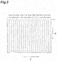
- FIG. 2 is a diagram illustrating a modulation plane 17 of the SLM 16.
- a plurality of modulation regions 17a are arranged along a certain direction A, and each modulation region 17a extends in a direction B intersecting with the direction A.
- the direction A is a dispersing direction by the dispersive element 12. Therefore, each of the spectrally dispersed wavelength components is incident on each of the plurality of modulation regions 17a.
- the SLM 16 modulates a phase and an intensity of each incident wavelength component in each modulation region 17a. Because the SLM 16 in the present embodiment is of the phase modulation type, the intensity modulation is realized by a phase pattern (phase image) presented on the modulation plane 17.
- Modulated light Lc including the respective wavelength components modulated by the SLM 16 is reflected again by the curved mirror 14 and reaches the dispersive element 12.
- the curved mirror 14 functions as a focusing optical system for focusing the modulated light Lc.
- the dispersive element 12 functions as a combining optical system and combines the respective wavelength components after the modulation. That is, by the curved mirror 14 and the dispersive element 12, the plurality of wavelength components of the modulated light Lc are focused and combined with each other and become the output light Ld.
- the output light Ld is light having a desired temporal intensity waveform different from the waveform of the input light La.
- the modulation pattern calculation apparatus 20 is a computer having an operation circuit such as a processor.
- the modulation pattern calculation apparatus 20 is electrically coupled to the SLM 16, calculates a phase modulation pattern to bring the temporal intensity waveform of the output light Ld close to a desired waveform, and provides a control signal including the phase modulation pattern to the SLM 16.
- the modulation pattern calculation apparatus 20 of the present embodiment presents, on the SLM 16, a phase pattern including a phase pattern for phase modulation that gives a phase spectrum for obtaining the desired waveform to the output light Ld and a phase pattern for intensity modulation that gives an intensity spectrum for obtaining the desired waveform to the output light Ld.
- the modulation pattern calculation apparatus 20 includes an arbitrary waveform input unit 21, a phase spectrum design unit 22, an intensity spectrum design unit 23, and a modulation pattern calculation unit 24.
- the operation circuit for example, the processor of the computer
- the respective functions may be realized by the same operation circuit or may be realized by different operation circuits.
- the operation circuit (for example, the processor of the computer) can realize the above respective functions by a modulation pattern calculation program. Therefore, the modulation pattern calculation program operates the operation circuit (for example, the processor of the computer) as the arbitrary waveform input unit 21, the phase spectrum design unit 22, the intensity spectrum design unit 23, and the modulation pattern calculation unit 24 in the modulation pattern calculation apparatus 20.
- the modulation pattern calculation program is stored in a storage device (non-transitory computer readable medium) inside or outside the computer.
- the arbitrary waveform input unit 21 receives the desired temporal intensity waveform input from an operator.
- the operator inputs information (for example, a pulse width) on the desired temporal intensity waveform to the arbitrary waveform input unit 21.
- the information on the desired temporal intensity waveform is given to the phase spectrum design unit 22 and the intensity spectrum design unit 23.
- the phase spectrum design unit 22 calculates a corresponding phase spectrum of the output light Ld, on the basis of the temporal intensity waveform.
- the intensity spectrum design unit 23 calculates a corresponding intensity spectrum of the output light Ld, on the basis of the temporal intensity waveform.
- a spectrum calculation method in the phase spectrum design unit 22 and the intensity spectrum design unit 23 will be described in detail later.
- the modulation pattern calculation unit 24 is an example of a modulation pattern calculation unit according to the present invention and calculates a phase modulation pattern to give the phase spectrum obtained in the phase spectrum design unit 22 and the intensity spectrum obtained in the intensity spectrum design unit 23 to the output light Ld. Further, a control signal including the calculated phase modulation pattern is provided to the SLM 16.
- FIG 3 is a graph illustrating an example of a combination of a certain phase spectrum G11 and a certain intensity spectrum G12.
- FIG. 3 is a graph illustrating a temporal intensity waveform of the output light Ld realized by the combination of the phase spectrum and the intensity spectrum illustrated in (a) in FIG. 3 .
- a horizontal axis shows a wavelength (nm)
- a left vertical axis shows an intensity value (arbitrary unit) of the intensity spectrum
- a right vertical axis shows a phase value (rad) of the phase spectrum.
- a horizontal axis shows a time (femtosecond) and a vertical axis shows a light intensity (arbitrary unit).
- the spectra and the waveform illustrated in FIG. 3 are examples, and the temporal intensity waveform of the output light Ld can be shaped in various forms by combinations of various phase spectra and intensity spectra.
- the desired temporal intensity waveform is represented as a function in a time domain, and the phase spectrum and the intensity spectrum are represented as functions in a frequency domain. Therefore, the phase spectrum and the intensity spectrum corresponding to the desired temporal intensity waveform are obtained by an iterative Fourier transform based on the desired temporal intensity waveform. In the method described below, the phase spectrum and the intensity spectrum are calculated using an iterative Fourier transform method. Therefore, as illustrated in FIG. 1 , the phase spectrum design unit 22 has an iterative Fourier transform unit 22a. Further, the intensity spectrum design unit 23 has an iterative Fourier transform unit 23a and a filtering process unit 23b.
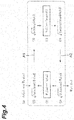
- FIG. 4 illustrates a calculation procedure in the iterative Fourier transform unit 22a of the phase spectrum design unit 22.
- the iterative Fourier transform unit 22a prepares an initial intensity spectrum function A 0 ( ⁇ ) and a phase spectrum function ⁇ 0 ( ⁇ ) to be functions of a frequency ⁇ (process number (1) in the drawing).
- the intensity spectrum function A 0 ( ⁇ ) and the phase spectrum function ⁇ 0 ( ⁇ ) represent the intensity spectrum and the phase spectrum of the input light La, respectively.
- the iterative Fourier transform unit 22a prepares a waveform function (a) in the frequency domain including the intensity spectrum function A 0 ( ⁇ ) and the phase spectrum function ⁇ n ( ⁇ ) (process number (2) in the drawing).
- a subscript n represents after an n-th Fourier transform process.
- the initial phase spectrum function ⁇ 0 ( ⁇ ) described above is used as the phase spectrum function ⁇ n ( ⁇ ).
- i is an imaginary number.
- the iterative Fourier transform unit 22a performs a Fourier transform from the frequency domain to the time domain on the function (a) (arrow A1 in the drawing).
- a waveform function (b) in the frequency domain including a temporal intensity waveform function b n (t) is obtained (process number (3) in the drawing).
- the iterative Fourier transform unit 22a replaces the temporal intensity waveform function b n (t) included in the function (b) by Target 0 (t) based on the desired waveform (process numbers (4) and (5) in the drawing).
- b n t : Targe t 0 t
- the iterative Fourier transform unit 22a performs an inverse Fourier transform from the time domain to the frequency domain on the function (d) (arrow A2 in the drawing).
- a waveform function (e) in the frequency domain including an intensity spectrum function B n ( ⁇ ) and the phase spectrum function ⁇ n ( ⁇ ) is obtained (process number (6) in the drawing).
- the iterative Fourier transform unit 22a repeatedly performs the above processes (1) to (7) a plurality of times, so that the phase spectrum form represented by the phase spectrum function ⁇ n ( ⁇ ) in the waveform function can be brought close to a phase spectrum form corresponding to the desired temporal intensity waveform.
- a phase spectrum function ⁇ IFTA ( ⁇ ) to be finally obtained is provided to the modulation pattern calculation unit 24.
- FIG. 5 illustrates a calculation procedure in the iterative Fourier transform unit 23a and the filtering process unit 23b of the intensity spectrum design unit 23.
- the iterative Fourier transform unit 23a prepares a waveform function (g) in the frequency domain including an intensity spectrum function A k ( ⁇ ) and the phase spectrum function ⁇ 0 ( ⁇ ) (process number (2) in the drawing).
- a subscript k represents after a k-th Fourier transform process.
- the iterative Fourier transform unit 23a performs the Fourier transform from the frequency domain to the time domain on the function (g) (arrow A3 in the drawing).
- a waveform function (h) in the frequency domain including a temporal intensity waveform function b k (t) is obtained (process number (3) in the drawing).
- the iterative Fourier transform unit 23a replaces the temporal intensity waveform function b k (t) included in the function (h) by a function Target 0 (t) based on the desired waveform (process numbers (4) and (5) in the drawing).
- b k t : Target 0 t
- the iterative Fourier transform unit 23a performs the inverse Fourier transform from the time domain to the frequency domain on the function (j) (arrow A4 in the drawing).
- a waveform function (k) in the frequency domain including an intensity spectrum function C k ( ⁇ ) and a phase spectrum function ⁇ k ( ⁇ ) is obtained (process number (6) in the drawing).
- the iterative Fourier transform unit 23a to constrain the phase spectrum function ⁇ k ( ⁇ ) included in the function (k), replaces the function by the initial phase spectrum function ⁇ 0 ( ⁇ ) (process number (7-a) in the drawing).
- ⁇ k ⁇ : ⁇ 0 ⁇
- the filtering process unit 23b performs a filtering process based on the intensity spectrum of the input light La, on the intensity spectrum function C k ( ⁇ ) in the frequency domain after the inverse Fourier transform. Specifically, a part exceeding a cutoff intensity for each wavelength determined on the basis of the intensity spectrum of the input light La in an intensity spectrum represented by the intensity spectrum function C k ( ⁇ ) is cut.
- the filtering process unit 23b replaces the intensity spectrum function C k ( ⁇ ) included in the function (k) by the intensity spectrum function A k ( ⁇ ) after the filtering process based on the formula (n).
- FIG. 6 is a flowchart illustrating a modulation pattern calculation method realized by the modulation pattern calculation apparatus 20 described above.
- information on a desired temporal intensity waveform is input to the arbitrary waveform input unit 21 by the operator (input step S1).
- a phase spectrum and an intensity spectrum to bring the temporal intensity waveform close to a desired waveform are calculated in the phase spectrum design unit 22 and the intensity spectrum design unit 23, respectively (phase spectrum calculation step S11 and intensity spectrum calculation step S21).
- An iterative Fourier transform step S12 by the iterative Fourier transform unit 22a is included in the phase spectrum calculation step S11.
- the Fourier transform is performed on the waveform function (formula (a)) in the frequency domain including the intensity spectrum function A 0 ( ⁇ ) and the phase spectrum function ⁇ n ( ⁇ ), the replacement of the temporal intensity waveform function based on the desired waveform is performed in the time domain after the Fourier transform (formula (c)), and the replacement to constrain the intensity spectrum function is performed in the frequency domain after the inverse Fourier transform (formula (f)).
- these processes are repeatedly performed a plurality of times, so that the phase spectrum function ⁇ n ( ⁇ ) is brought close to a phase spectrum form corresponding to the desired waveform.
- a phase spectrum function ⁇ IFTA ( ⁇ ) to be finally obtained is provided to a next modulation pattern calculation step S3.
- an iterative Fourier transform step S22 by the iterative Fourier transform unit 23a and a filtering process step S23 by the filtering process unit 23b are included in the intensity spectrum calculation step S21.
- the Fourier transform is performed on the waveform function (formula (g)) in the frequency domain including the intensity spectrum function A k ( ⁇ ) and the phase spectrum function ⁇ 0 ( ⁇ ), the replacement of the temporal intensity waveform function based on the desired waveform is performed in the time domain after the Fourier transform (formula (i)), and the replacement to constrain the phase spectrum function is performed in the frequency domain after the inverse Fourier transform (formula (m)).
- the filtering process of cutting the part exceeding the cutoff intensity for each wavelength determined on the basis of the intensity spectrum of the input light La is performed on the intensity spectrum function in the frequency domain after the inverse Fourier transform (formula (n)). Further, the iterative Fourier transform step S22 and the filtering process step S23 are repeatedly performed a plurality of times, so that the intensity spectrum function A k ( ⁇ ) is brought close to an intensity spectrum form corresponding to the desired waveform. An intensity spectrum function A IFTA ( ⁇ ) to be finally obtained is provided to the next modulation pattern calculation step S3.
- a modulation pattern is calculated on the basis of the phase spectrum function ⁇ IFTA ( ⁇ ) and the intensity spectrum function A IFTA ( ⁇ ).
- the modulation pattern is presented on the SLM 16.
- the intensity spectrum when the intensity spectrum is designed, a calculation method different from a method for the phase spectrum is adopted. If the intensity spectrum is calculated by the same calculation method as the method for the phase spectrum, an intensity spectrum larger than the intensity spectrum of the input light may be calculated depending on a wavelength region.
- FIG. 7 is a graph illustrating an example of such a state, and a vertical axis represents an intensity and a horizontal axis represents a frequency. Further, a dashed line G21 represents an intensity spectrum of the input light La (refer to FIG. 1 ) and a solid line G22 represents a calculated intensity spectrum.
- intensity of a region D1 shown by hatching exceeds intensity of the intensity spectrum G21 of the input light La.
- the intensity spectrum G22 cannot be realized in the output light Ld, and for this reason, even if an intensity modulation pattern is generated on the basis of the intensity spectrum G22, the temporal intensity waveform of the output light Ld does not become the desired waveform.
- the filtering process based on the intensity spectrum of the input light La is performed on the intensity spectrum obtained by the inverse Fourier transform. That is, as shown by a graph G23 in FIG. 8 , a part (region D1 in FIG 7 ) exceeding the cutoff intensity for each wavelength determined on the basis of the intensity spectrum of the input light La is cut.
- the intensity spectrum (function A IFTA ( ⁇ )) provided to the modulation pattern calculation unit 24 (modulation pattern calculation step S3) can be suppressed to the extent that the intensity spectrum does not exceed the intensity spectrum of the input light La. Therefore, according to the present embodiment, the intensity spectrum to bring the temporal intensity waveform of the output light Ld close to the desired waveform can be easily calculated using the iterative Fourier transform. Further, for example, as compared with a method of measuring a waveform of light after shaping and determining an intensity spectrum after trial and error, accuracy of a realized waveform with respect to the desired waveform can be improved. Furthermore, because the intensity loss is limited to a region D2 in FIG. 8 , the intensity loss accompanying the intensity spectrum modulation can be suppressed minimally as compared with the case in which the entire intensity spectrum is reduced.
- the process (iterative Fourier transform step S22) by the iterative Fourier transform unit 23a and the process (filtering process step S23) by the filtering process unit 23b are repeatedly performed, however, each of these processes may be performed once. Even in this case, the above effects can be surely obtained.
- the iterative Fourier transform is repeatedly performed with the filtering process being performed, so that the intensity spectrum to bring the temporal intensity waveform of the output light Ld close to the desired waveform can be obtained more accurately.
- the cutoff intensity for each wavelength in the filtering process may substantially coincide with the intensity spectrum of the input light La.
- the intensity loss can be suppressed minimally while the intensity spectrum provided to the modulation pattern calculation unit 24 (modulation pattern calculation step S3) is maintained at the intensity equal to or smaller than the intensity spectrum of the input light La.
- FIG 9 includes graphs illustrating such a process.
- a graph G24 illustrated in (a) in FIG. 9 is an example of the normalized intensity spectrum function C' k ( ⁇ ) obtained by multiplying the graph G22 (that is, the intensity spectrum function C k ( ⁇ )) illustrated in FIG. 7 by the normalization coefficient a (a ⁇ 1).
- a graph G25 illustrated in (b) in FIG. 9 is obtained by performing the filtering process on the graph G24 with the graph G21 as the cutoff intensity. Even in this calculation method, the same effects as the effects according to the above embodiment can be obtained.
- the normalization coefficient may have a value in which a maximum value of the intensity spectrum function C' k ( ⁇ ) after the multiplication of the coefficient is substantially equal to a maximum value of the intensity spectrum of the input light La, or may have a value smaller than the above value.
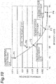
- FIG. 10 is a graph illustrating a relation between intensity loss and waveform accuracy when the normalization coefficient is changed, in the case where a double pulse (two pulses having a time difference) is set as a desired temporal intensity waveform.
- a double pulse two pulses having a time difference
- a standard deviation with respect to the desired waveform is used as an index of the waveform accuracy.
- a coefficient in the case of performing normalization such that the maximum value of the intensity spectrum function C' k ( ⁇ ) is equal to the maximum value of the intensity spectrum of the input light La is set as 1.0
- plots P1 to P4 when the normalization coefficients are set as 1.0, 0.75, 0.5, and 0.25, respectively, are illustrated in FIG. 10 .
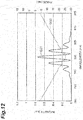
- FIG. 11 and FIG. 12 illustrate intensity spectra (graph G31) when the normalization coefficients are set as 1.0 and 0.75, respectively.
- a graph G32 in FIG. 11 and FIG. 12 is a phase spectrum and is fixed regardless of the normalization coefficient.
- a suitable normalization coefficient may be determined according to a purpose and a use. For example, when the large intensity loss can be allowed, the waveform accuracy can be remarkably improved (to the extent that the standard deviation becomes almost zero) by decreasing the normalization coefficient.
- FIG. 10 also illustrates a plot P0 when COS type intensity modulation is applied as a comparative example.
- the standard deviation becomes 0.008 at the intensity loss of 50%.
- the standard deviation becomes 0.0064 at the same intensity loss (50%).
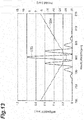
- FIG. 13 illustrates an intensity spectrum (graph G33) when the COS type intensity modulation is applied.
- a graph G34 in FIG 13 is a phase spectrum.
- FIG. 14 is a graph illustrating a relation of intensity loss and full width at half maximum (FWHM) when a normalization coefficient is changed, in the case in which a single pulse (of a time width shorter than a time width of a transform limited (TL) pulse) is set as a desired temporal intensity waveform.
- FWHM full width at half maximum
- plots P5 to P8 when the normalization coefficients are set as 1.0, 0.75, 0.5, and 0.25, respectively, are illustrated.
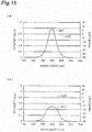
- (a) in FIG. 15 and (b) in FIG. 15 illustrate intensity spectra (graph G41) when the normalization coefficients are set as 1.0 and 0.5, respectively.
- a graph G42 in (a) in FIG. 15 and (b) in FIG. 15 is a phase spectrum and is fixed regardless of the normalization coefficient.
- a suitable normalization coefficient may be determined according to a purpose and a use.
- the normalization coefficient is set as a value less than 1.0, so that a light pulse of a time width shorter than a time width of a temporal waveform (it is called a transform limited pulse (TL pulse), FWHM is 135.5 fs) when the phase spectrum is flat and the intensity modulation is not performed can be generated.
- a light pulse of a time width shorter than a time width of a temporal waveform it is called a transform limited pulse (TL pulse)
- FWHM 135.5 fs
- FIG. 16 illustrates a TL pulse waveform (G51) and a waveform (G52) when the normalization coefficient is set as 0.25.
- the modulation pattern calculation apparatus, the light control apparatus, the modulation pattern calculation method, and the modulation pattern calculation program according to one aspect of the present invention are not limited to the embodiments and the modifications described above, and various other modifications are enabled.
- both the intensity spectrum and the phase spectrum to bring the temporal intensity waveform of the output light close to the desired waveform are calculated and the modulation pattern presented on the SLM is generated on the basis of these spectra.
- only the intensity spectrum to bring the output light close to the desired waveform may be calculated and the modulation pattern may be generated on the basis of the intensity spectrum and a previously prepared (or selected) phase spectrum.
- only the intensity spectrum to bring the output light close to the desired waveform may be calculated and the modulation pattern to modulate only the intensity spectrum without modulating the phase spectrum may be generated.
- the modulation pattern calculation apparatus is an apparatus for calculating a modulation pattern presented on a spatial light modulator for modulating an intensity spectrum of input light to bring a temporal intensity waveform of light close to a desired waveform
- the apparatus includes an iterative Fourier transform unit for performing a Fourier transform on a waveform function in a frequency domain including an intensity spectrum function and a phase spectrum function, performing a replacement of a temporal intensity waveform function based on the desired waveform in a time domain after the Fourier transform and then performing an inverse Fourier transform, and performing a replacement to constrain the phase spectrum function in the frequency domain after the inverse Fourier transform; a filtering process unit for performing a filtering process of cutting a part exceeding a cutoff intensity for each wavelength determined on the basis of the intensity spectrum of the input light, on the intensity spectrum function in the frequency domain after the inverse Fourier transform or a normalized intensity spectrum function obtained by multiplying the intensity spectrum function by a normalization coefficient; and a modulation pattern calculation unit for calculating the modul
- the modulation pattern calculation method is a method for calculating a modulation pattern presented on a spatial light modulator for modulating an intensity spectrum of input light to bring a temporal intensity waveform of light close to a desired waveform
- the method includes an iterative Fourier transform step of performing a Fourier transform on a waveform function in a frequency domain including an intensity spectrum function and a phase spectrum function, performing a replacement of a temporal intensity waveform function based on the desired waveform in a time domain after the Fourier transform and then performing an inverse Fourier transform, and performing a replacement to constrain the phase spectrum function in the frequency domain after the inverse Fourier transform; a filtering process step of performing a filtering process of cutting a part exceeding a cutoff intensity for each wavelength determined on the basis of the intensity spectrum of the input light, on the intensity spectrum function in the frequency domain after the inverse Fourier transform or a normalized intensity spectrum function obtained by multiplying the intensity spectrum function by a normalization coefficient; and a modulation pattern calculation step of
- the modulation pattern calculation program operates a computer, in a modulation pattern calculation apparatus for calculating a modulation pattern presented on a spatial light modulator for modulating an intensity spectrum of input light to bring a temporal intensity waveform of light close to a desired waveform, as an iterative Fourier transform unit for performing a Fourier transform on a waveform function in a frequency domain including an intensity spectrum function and a phase spectrum function, performing a replacement of a temporal intensity waveform function based on the desired waveform in a time domain after the Fourier transform and then performing an inverse Fourier transform, and performing a replacement to constrain the phase spectrum function in the frequency domain after the inverse Fourier transform; a filtering process unit for performing a filtering process of cutting a part exceeding a cutoff intensity for each wavelength determined on the basis of the intensity spectrum of the input light, on the intensity spectrum function in the frequency domain after the inverse Fourier transform or a normalized intensity spectrum function obtained by multiplying the intensity spectrum function by a normalization coefficient; and a modul
- the process (iterative Fourier transform step) by the iterative Fourier transform unit and the process (filtering process step) by the filtering process unit may be repeatedly performed, and in the modulation pattern calculation step, the modulation pattern calculation unit may calculate the modulation pattern on the basis of the intensity spectrum function or the normalized intensity spectrum function obtained by the filtering process after the repetition.
- the iterative Fourier transform is repeatedly performed with the filtering process being performed, so that the intensity spectrum to bring the temporal intensity waveform of the light close to the desired waveform can be obtained more accurately.
- the cutoff intensity for each wavelength in the filtering process may coincide with the intensity spectrum of the input light.
- the intensity loss can be suppressed minimally while the intensity spectrum provided to the modulation pattern calculation unit (modulation pattern calculation step) is maintained at the intensity equal to or smaller than the intensity spectrum of the input light.
- the coefficient may have a value in which a maximum value of the intensity spectrum represented by the normalized intensity spectrum function is substantially equal to a maximum value of the intensity spectrum of the input light.
- the light control apparatus includes the modulation pattern calculation apparatus described above; a light source for outputting the input light; a dispersive element for spectrally dispersing the input light; a spatial light modulator for modulating the intensity spectrum of the input light after the dispersion and outputting modulated light; and an optical system for focusing the modulated light.
- the spatial light modulator presents the modulation pattern calculated by the modulation pattern calculation apparatus.
- the modulation pattern calculation apparatus described above is included, so that the intensity spectrum to bring the temporal waveform of the light close to the desired waveform can be easily calculated.
- the present invention can be used as a modulation pattern calculation apparatus, a light control apparatus, a modulation pattern calculation method, a modulation pattern calculation program, and a computer readable medium capable of easily calculating an intensity spectrum to bring a temporal waveform of light close to a desired waveform.
- 1A - light control apparatus 2 - light source, 10 - optical system, 12 - dispersive element, 14 - curved mirror, 16 - spatial light modulator (SLM), 17 - modulation plane, 17a - modulation region, 20 - modulation pattern calculation apparatus, 21 - arbitrary waveform input unit, 22 - phase spectrum design unit, 22a - iterative Fourier transform unit, 23 - intensity spectrum design unit, 23a - iterative Fourier transform unit, 23b - filtering process unit, 24 - modulation pattern calculation unit, La - input light, Ld - output light.
- SLM spatial light modulator
Landscapes
- Physics & Mathematics (AREA)
- Nonlinear Science (AREA)
- General Physics & Mathematics (AREA)
- Optics & Photonics (AREA)
- Chemical & Material Sciences (AREA)
- Crystallography & Structural Chemistry (AREA)
- Mathematical Physics (AREA)
- Optical Modulation, Optical Deflection, Nonlinear Optics, Optical Demodulation, Optical Logic Elements (AREA)
- Liquid Crystal (AREA)
Abstract
Description
- An aspect of the present invention relates to a modulation pattern calculation apparatus, a light control apparatus, a modulation pattern calculation method, a modulation pattern calculation program, and a computer readable medium.
-
Non Patent Document 1 discloses technology for modulating a phase spectrum using a spatial light modulator (SLM) to shape a light pulse. In this document, a phase spectrum to obtain a desired light pulse waveform is calculated using an iterative Fourier method (iterative Fourier transform algorithm: IFTA). - Non Patent Document 1: M. Hacker, G. Stobrawa, T. Feurer, "Iterative Fourier transform algorithm for phase-only pulse shaping", Optics Express, Vol. 9, No. 4, pp. 191-199, 13 August 2001
- For example, as technology for controlling a temporal waveform of a variety of light such as ultrashort pulse light, technology for modulating a phase spectrum and an intensity spectrum of a light pulse by the SLM is known. In this technology, a phase spectrum and an intensity spectrum to bring the temporal waveform of the light close to a desired waveform are calculated, and a modulation pattern to give the phase spectrum and the intensity spectrum to the light is presented on the SLM.
- For the phase spectrum, the spectrum can be calculated using the normal iterative Fourier method, for example as in
Non Patent Document 1 described above. On the other hand, for the intensity spectrum, it is difficult to calculate the spectrum in the normal iterative Fourier method. When the spectrum is calculated using the normal iterative Fourier method, an intensity spectrum larger than the intensity spectrum of the input light to the SLM may be calculated depending on a wavelength region, and it is difficult to generate light having the intensity spectrum from the input light. For this reason, in the conventional method, for example, a method of measuring a waveform of light after shaping and determining an intensity spectrum after trial and error is adopted, and there are problems in that time and effort are taken, and skill is required to obtain an intensity spectrum with high accuracy. - An object of one aspect of the present invention is to provide a modulation pattern calculation apparatus, a light control apparatus, a modulation pattern calculation method, a modulation pattern calculation program, and a computer readable medium capable of easily calculating an intensity spectrum to bring a temporal waveform of light close to a desired waveform.
- In order to solve the above problem, a modulation pattern calculation apparatus according to one aspect of the present invention is an apparatus for calculating a modulation pattern presented on a spatial light modulator for modulating an intensity spectrum of input light to bring a temporal intensity waveform of light close to a desired waveform, and the apparatus includes an iterative Fourier transform unit for performing a Fourier transform on a waveform function in a frequency domain including an intensity spectrum function and a phase spectrum function, performing a replacement of a temporal intensity waveform function based on the desired waveform in a time domain after the Fourier transform and then performing an inverse Fourier transform, and performing a replacement to constrain the phase spectrum function in the frequency domain after the inverse Fourier transform; a filtering process unit for performing a filtering process of cutting a part exceeding a cutoff intensity for each wavelength determined on the basis of the intensity spectrum of the input light, on the intensity spectrum function in the frequency domain after the inverse Fourier transform or a normalized intensity spectrum function obtained by multiplying the intensity spectrum function by a normalization coefficient; and a modulation pattern calculation unit for calculating the modulation pattern on the basis of the intensity spectrum function or the normalized intensity spectrum function after the filtering process.
- Further, a modulation pattern calculation method according to one aspect of the present invention is a method for calculating a modulation pattern presented on a spatial light modulator for modulating an intensity spectrum of input light to bring a temporal intensity waveform of light close to a desired waveform, and the method includes a step (Fourier transform step) of performing a Fourier transform on a waveform function in a frequency domain including an intensity spectrum function and a phase spectrum function; a step (inverse Fourier transform step) of performing a replacement of a temporal intensity waveform function based on the desired waveform in a time domain after the Fourier transform and then performing an inverse Fourier transform; a step (replacement step) of performing a replacement to constrain the phase spectrum function in the frequency domain after the inverse Fourier transform; a step (filtering process step) of performing a filtering process of cutting a part exceeding a cutoff intensity for each wavelength determined on the basis of the intensity spectrum of the input light, on the intensity spectrum function in the frequency domain after the inverse Fourier transform or a normalized intensity spectrum function obtained by multiplying the intensity spectrum function by a normalization coefficient; and a step (modulation pattern calculation step) of calculating the modulation pattern on the basis of the intensity spectrum function or the normalized intensity spectrum function after the filtering process.
- Further, a modulation pattern calculation program according to one aspect of the present invention is a program for causing a computer to calculate a modulation pattern presented on a spatial light modulator for modulating an intensity spectrum of input light to bring a temporal intensity waveform of light close to a desired waveform, and the program causes the computer to execute a step (Fourier transform step) of performing a Fourier transform on a waveform function in a frequency domain including an intensity spectrum function and a phase spectrum function; a step (inverse Fourier transform step) of performing a replacement of a temporal intensity waveform function based on the desired waveform in a time domain after the Fourier transform and then performing an inverse Fourier transform; a step (replacement step) of performing a replacement to constrain the phase spectrum function in the frequency domain after the inverse Fourier transform; a step (filtering process step) of performing a filtering process of cutting a part exceeding a cutoff intensity for each wavelength determined on the basis of the intensity spectrum of the input light, on the intensity spectrum function in the frequency domain after the inverse Fourier transform or a normalized intensity spectrum function obtained by multiplying the intensity spectrum function by a normalization coefficient; and a step (modulation pattern calculation step) of calculating the modulation pattern on the basis of the intensity spectrum function or the normalized intensity spectrum function after the filtering process.
- In the above apparatus, the method, and the program, the intensity spectrum to bring the temporal intensity waveform of the light close to the desired waveform is calculated in the iterative Fourier transform unit or the replacement step. At that time, as described above, an intensity spectrum larger than the intensity spectrum of the input light may be calculated depending on a wavelength region. Therefore, in the above apparatus and the method, the filtering process based on the intensity spectrum of the input light is performed on the intensity spectrum (or the intensity spectrum obtained by multiplying the intensity spectrum by the normalization coefficient) obtained by the inverse Fourier transform. That is, the part exceeding the cutoff intensity for each wavelength determined on the basis of the intensity spectrum of the input light is cut. As a result, the intensity spectrum provided to the modulation pattern calculation unit or the modulation pattern calculation step can be suppressed to the extent that the intensity spectrum does not exceed the intensity spectrum of the input light. Therefore, according to the above apparatus and the method, the intensity spectrum to bring the temporal intensity waveform of the light close to the desired waveform can be easily calculated using the iterative Fourier transform.
- Further, a light control apparatus according to one aspect of the present invention includes the modulation pattern calculation apparatus having the above configuration; a light source for outputting the input light; a dispersive element for spectrally dispersing the input light; a spatial light modulator for modulating the intensity spectrum of the input light after the dispersion and outputting modulated light; and an optical system for focusing the modulated light. The spatial light modulator presents the modulation pattern calculated by the modulation pattern calculation apparatus.
- According to this apparatus, the modulation pattern calculation apparatus having the above configuration is included, so that the intensity spectrum to bring the temporal waveform of the light close to the desired waveform can be easily calculated.
- According to a modulation pattern calculation apparatus, a light control apparatus, a modulation pattern calculation method, a modulation pattern calculation program, and a computer readable medium according to one aspect of the present invention, an intensity spectrum to bring a temporal waveform of light close to a desired waveform can be easily calculated.
-
- [
FIG. 1] FIG. 1 is a diagram schematically illustrating a configuration of a light control apparatus according to an embodiment. - [
FIG. 2] FIG. 2 is a diagram illustrating a modulation plane of an SLM. - [
FIG. 3] FIG. 3 includes (a) a graph illustrating an example of a combination of a certain phase spectrum and a certain intensity spectrum, and (b) a graph illustrating a temporal intensity waveform of output light realized by the combination of the phase spectrum and the intensity spectrum illustrated in (a) inFIG. 3 . - [
FIG. 4] FIG. 4 is a diagram illustrating a calculation procedure in an iterative Fourier transform unit of a phase spectrum design unit. - [
FIG 5] FIG. 5 is a diagram illustrating a calculation procedure in an iterative Fourier transform unit and a filtering process unit of an intensity spectrum design unit. - [
FIG 6] FIG. 6 is a flowchart illustrating a modulation pattern calculation method. - [
FIG. 7] FIG 7 is a diagram illustrating an intensity spectrum of input light and a calculated intensity spectrum. - [
FIG. 8] FIG. 8 is a diagram illustrating a result of cutting a part exceeding a cutoff intensity for each wavelength determined on the basis of an intensity spectrum of input light. - [
FIG 9] FIG. 9 includes (a) a diagram illustrating an example of an intensity spectrum obtained by multiplying a calculated intensity spectrum by a normalization coefficient, and (b) a diagram illustrating a result of performing a filtering process on the intensity spectrum of (a) inFIG. 9 . - [
FIG. 10] FIG. 10 is a graph illustrating a relation between intensity loss and waveform accuracy when a normalization coefficient is changed, in the case where a double pulse is set as a desired temporal intensity waveform. - [
FIG 11] FIG. 11 is a diagram illustrating an intensity spectrum when a normalization coefficient is set as 1.0. - [
FIG. 12] FIG. 12 is a diagram illustrating an intensity spectrum when a normalization coefficient is set as 0.75. - [
FIG. 13] FIG 13 is a diagram illustrating an intensity spectrum when COS type intensity modulation is applied. - [
FIG. 14] FIG. 14 is a graph illustrating a relation between intensity loss and full width at half maximum when a normalization coefficient is changed, in the case where a single pulse is set as a desired temporal intensity waveform. - [
FIG. 15] FIG. 15 includes (a), (b) diagrams illustrating intensity spectra when normalization coefficients are set as 1.0 and 0.5, respectively. - [
FIG. 16] FIG. 16 is a diagram illustrating a TL pulse waveform and a waveform when a normalization coefficient is set as 0.25. - Hereinafter, embodiments of a modulation pattern calculation apparatus, a light control apparatus, a modulation pattern calculation method, and a modulation pattern calculation program according to one aspect of the present invention will be described in detail with reference to the accompanying drawings. In the description of the drawings, the same elements will be denoted by the same reference signs, without redundant description.
-
FIG. 1 is a diagram schematically illustrating a configuration of alight control apparatus 1A according to an embodiment of the present invention. Thelight control apparatus 1A according to the present embodiment generates, from input light La, output light Ld having an arbitrary temporal intensity waveform different from that of the input light La. As illustrated inFIG. 1 , thelight control apparatus 1A includes alight source 2, anoptical system 10, and a modulationpattern calculation apparatus 20. - The
light source 2 outputs the input light La input to theoptical system 10. Thelight source 2 is a laser light source such as a solid-state laser light source, for example, and the input light La is coherent pulse light, for example. - The
optical system 10 has adispersive element 12, acurved mirror 14, and anSLM 16. Thedispersive element 12 is optically coupled to thelight source 2, and the SLM 16 is optically coupled to thedispersive element 12 via thecurved mirror 14. Thedispersive element 12 spectrally disperses the input light La for each wavelength component. Thedispersive element 12 has a diffraction grating formed on a plate surface, for example. Further, thedispersive element 12 may have a prism. The input light La is obliquely incident on the diffraction grating, and is spectrally dispersed into a plurality of wavelength components. Light Lb including the plurality of wavelength components reaches thecurved mirror 14. The light Lb is reflected by thecurved mirror 14 and reaches theSLM 16. - The SLM 16 simultaneously performs phase modulation and intensity modulation of the light Lb to generate the output light Ld having an arbitrary temporal intensity waveform different from the waveform of the input light La. The SLM 16 is of a phase modulation type, for example. In one example, the
SLM 16 is of an LCOS (liquid crystal on silicon) type. -
FIG. 2 is a diagram illustrating amodulation plane 17 of theSLM 16. As illustrated inFIG. 2 , in themodulation plane 17, a plurality ofmodulation regions 17a are arranged along a certain direction A, and eachmodulation region 17a extends in a direction B intersecting with the direction A. The direction A is a dispersing direction by thedispersive element 12. Therefore, each of the spectrally dispersed wavelength components is incident on each of the plurality ofmodulation regions 17a. TheSLM 16 modulates a phase and an intensity of each incident wavelength component in eachmodulation region 17a. Because theSLM 16 in the present embodiment is of the phase modulation type, the intensity modulation is realized by a phase pattern (phase image) presented on themodulation plane 17. - Modulated light Lc including the respective wavelength components modulated by the
SLM 16 is reflected again by thecurved mirror 14 and reaches thedispersive element 12. At this time, thecurved mirror 14 functions as a focusing optical system for focusing the modulated light Lc. Further, thedispersive element 12 functions as a combining optical system and combines the respective wavelength components after the modulation. That is, by thecurved mirror 14 and thedispersive element 12, the plurality of wavelength components of the modulated light Lc are focused and combined with each other and become the output light Ld. The output light Ld is light having a desired temporal intensity waveform different from the waveform of the input light La. - The modulation
pattern calculation apparatus 20 is a computer having an operation circuit such as a processor. The modulationpattern calculation apparatus 20 is electrically coupled to theSLM 16, calculates a phase modulation pattern to bring the temporal intensity waveform of the output light Ld close to a desired waveform, and provides a control signal including the phase modulation pattern to theSLM 16. - The modulation
pattern calculation apparatus 20 of the present embodiment presents, on theSLM 16, a phase pattern including a phase pattern for phase modulation that gives a phase spectrum for obtaining the desired waveform to the output light Ld and a phase pattern for intensity modulation that gives an intensity spectrum for obtaining the desired waveform to the output light Ld. For this purpose, the modulationpattern calculation apparatus 20 includes an arbitrarywaveform input unit 21, a phasespectrum design unit 22, an intensityspectrum design unit 23, and a modulationpattern calculation unit 24. That is, the operation circuit (for example, the processor of the computer) provided in the modulationpattern calculation apparatus 20 realizes a function of the arbitrarywaveform input unit 21, a function of the phasespectrum design unit 22, a function of the intensityspectrum design unit 23, and a function of the modulationpattern calculation unit 24. The respective functions may be realized by the same operation circuit or may be realized by different operation circuits. - The operation circuit (for example, the processor of the computer) can realize the above respective functions by a modulation pattern calculation program. Therefore, the modulation pattern calculation program operates the operation circuit (for example, the processor of the computer) as the arbitrary
waveform input unit 21, the phasespectrum design unit 22, the intensityspectrum design unit 23, and the modulationpattern calculation unit 24 in the modulationpattern calculation apparatus 20. The modulation pattern calculation program is stored in a storage device (non-transitory computer readable medium) inside or outside the computer. - The arbitrary
waveform input unit 21 receives the desired temporal intensity waveform input from an operator. The operator inputs information (for example, a pulse width) on the desired temporal intensity waveform to the arbitrarywaveform input unit 21. - The information on the desired temporal intensity waveform is given to the phase
spectrum design unit 22 and the intensityspectrum design unit 23. The phasespectrum design unit 22 calculates a corresponding phase spectrum of the output light Ld, on the basis of the temporal intensity waveform. The intensityspectrum design unit 23 calculates a corresponding intensity spectrum of the output light Ld, on the basis of the temporal intensity waveform. Here, a spectrum calculation method in the phasespectrum design unit 22 and the intensityspectrum design unit 23 will be described in detail later. - The modulation
pattern calculation unit 24 is an example of a modulation pattern calculation unit according to the present invention and calculates a phase modulation pattern to give the phase spectrum obtained in the phasespectrum design unit 22 and the intensity spectrum obtained in the intensityspectrum design unit 23 to the output light Ld. Further, a control signal including the calculated phase modulation pattern is provided to theSLM 16. - Here, a method of calculating a phase spectrum and an intensity spectrum corresponding to a desired temporal intensity waveform is described in detail. (a) in
FIG 3 is a graph illustrating an example of a combination of a certain phase spectrum G11 and a certain intensity spectrum G12. Further, (b) inFIG. 3 is a graph illustrating a temporal intensity waveform of the output light Ld realized by the combination of the phase spectrum and the intensity spectrum illustrated in (a) inFIG. 3 . In (a) inFIG. 3 , a horizontal axis shows a wavelength (nm), a left vertical axis shows an intensity value (arbitrary unit) of the intensity spectrum, and a right vertical axis shows a phase value (rad) of the phase spectrum. Further, in (b) inFIG. 3 , a horizontal axis shows a time (femtosecond) and a vertical axis shows a light intensity (arbitrary unit). The spectra and the waveform illustrated inFIG. 3 are examples, and the temporal intensity waveform of the output light Ld can be shaped in various forms by combinations of various phase spectra and intensity spectra. - The desired temporal intensity waveform is represented as a function in a time domain, and the phase spectrum and the intensity spectrum are represented as functions in a frequency domain. Therefore, the phase spectrum and the intensity spectrum corresponding to the desired temporal intensity waveform are obtained by an iterative Fourier transform based on the desired temporal intensity waveform. In the method described below, the phase spectrum and the intensity spectrum are calculated using an iterative Fourier transform method. Therefore, as illustrated in
FIG. 1 , the phasespectrum design unit 22 has an iterativeFourier transform unit 22a. Further, the intensityspectrum design unit 23 has an iterativeFourier transform unit 23a and afiltering process unit 23b. -
FIG. 4 illustrates a calculation procedure in the iterativeFourier transform unit 22a of the phasespectrum design unit 22. First, the iterativeFourier transform unit 22a prepares an initial intensity spectrum function A0(ω) and a phase spectrum function Ψ0(ω) to be functions of a frequency ω (process number (1) in the drawing). In one example, the intensity spectrum function A0(ω) and the phase spectrum function Ψ0(ω) represent the intensity spectrum and the phase spectrum of the input light La, respectively. - Next, the iterative
Fourier transform unit 22a prepares a waveform function (a) in the frequency domain including the intensity spectrum function A0(ω) and the phase spectrum function Ψn(ω) (process number (2) in the drawing).
[Formula 1]
- Next, the iterative
Fourier transform unit 22a performs a Fourier transform from the frequency domain to the time domain on the function (a) (arrow A1 in the drawing). As a result, a waveform function (b) in the frequency domain including a temporal intensity waveform function bn(t) is obtained (process number (3) in the drawing).
[Formula 2]
- Next, the iterative
Fourier transform unit 22a replaces the temporal intensity waveform function bn(t) included in the function (b) by Target0(t) based on the desired waveform (process numbers (4) and (5) in the drawing).
[Formula 3]

- Next, the iterative
Fourier transform unit 22a performs an inverse Fourier transform from the time domain to the frequency domain on the function (d) (arrow A2 in the drawing). As a result, a waveform function (e) in the frequency domain including an intensity spectrum function Bn(ω) and the phase spectrum function Ψn(ω) is obtained (process number (6) in the drawing).
[Formula 5]
- Next, the iterative
Fourier transform unit 22a, to constrain the intensity spectrum function Bn(ω) included in the function (e), replaces the function by the initial intensity spectrum function A0(ω) (process number (7) in the drawing).
[Formula 6]
- Subsequently, the iterative
Fourier transform unit 22a repeatedly performs the above processes (1) to (7) a plurality of times, so that the phase spectrum form represented by the phase spectrum function Ψn(ω) in the waveform function can be brought close to a phase spectrum form corresponding to the desired temporal intensity waveform. A phase spectrum function ΨIFTA(ω) to be finally obtained is provided to the modulationpattern calculation unit 24. -
FIG. 5 illustrates a calculation procedure in the iterativeFourier transform unit 23a and thefiltering process unit 23b of the intensityspectrum design unit 23. First, similar to when the phase spectrum is calculated, the iterativeFourier transform unit 23a prepares an initial intensity spectrum function Ak=0(ω) and a phase spectrum function Ψ0(ω) (process number (1) in the drawing). Next, the iterativeFourier transform unit 23a prepares a waveform function (g) in the frequency domain including an intensity spectrum function Ak(ω) and the phase spectrum function Ψ0(ω) (process number (2) in the drawing).
[Formula 7]
- Next, the iterative
Fourier transform unit 23a performs the Fourier transform from the frequency domain to the time domain on the function (g) (arrow A3 in the drawing). As a result, a waveform function (h) in the frequency domain including a temporal intensity waveform function bk(t) is obtained (process number (3) in the drawing).
[Formula 8]
- Next, the iterative
Fourier transform unit 23a replaces the temporal intensity waveform function bk(t) included in the function (h) by a function Target0(t) based on the desired waveform (process numbers (4) and (5) in the drawing).
[Formula 9]

- Next, the iterative
Fourier transform unit 23a performs the inverse Fourier transform from the time domain to the frequency domain on the function (j) (arrow A4 in the drawing). As a result, a waveform function (k) in the frequency domain including an intensity spectrum function Ck(ω) and a phase spectrum function Ψk(ω) is obtained (process number (6) in the drawing).
[Formula 11]
Fourier transform unit 23a, to constrain the phase spectrum function Ψk(ω) included in the function (k), replaces the function by the initial phase spectrum function Ψ0(ω) (process number (7-a) in the drawing).
[Formula 12]
- Further, the
filtering process unit 23b performs a filtering process based on the intensity spectrum of the input light La, on the intensity spectrum function Ck(ω) in the frequency domain after the inverse Fourier transform. Specifically, a part exceeding a cutoff intensity for each wavelength determined on the basis of the intensity spectrum of the input light La in an intensity spectrum represented by the intensity spectrum function Ck(ω) is cut. - In one example, the cutoff intensity for each wavelength is set to coincide with the intensity spectrum of the input light La (in the present embodiment, the initial intensity spectrum function Ak=0(ω)). In this case, as shown by the following formula (n), at a frequency where the intensity spectrum function Ck(ω) is larger than the initial intensity spectrum function Ak=0(ω), a value of the initial intensity spectrum function Ak=0(ω)) is taken as a value of the intensity spectrum function Ak(ω). Further, at a frequency where the intensity spectrum function Ck(ω) is equal to or smaller than the initial intensity spectrum function Ak=0(ω), a value of the intensity spectrum function Ck(ω) is taken as the value of the intensity spectrum function Ak(ω) (process number (7-b) in the drawing).
[Formula 13]
filtering process unit 23b replaces the intensity spectrum function Ck(ω) included in the function (k) by the intensity spectrum function Ak(ω) after the filtering process based on the formula (n). - Subsequently, the above processes (1) to (7-b) are repeatedly performed, so that the intensity spectrum form represented by the intensity spectrum function Ak(ω) in the waveform function can be brought close to an intensity spectrum form corresponding to the desired temporal intensity waveform. An intensity spectrum function AIFTA(ω) to be finally obtained is provided to the modulation
pattern calculation unit 24. -
FIG. 6 is a flowchart illustrating a modulation pattern calculation method realized by the modulationpattern calculation apparatus 20 described above. As illustrated inFIG. 6 , first, information on a desired temporal intensity waveform is input to the arbitrarywaveform input unit 21 by the operator (input step S1). Next, a phase spectrum and an intensity spectrum to bring the temporal intensity waveform close to a desired waveform are calculated in the phasespectrum design unit 22 and the intensityspectrum design unit 23, respectively (phase spectrum calculation step S11 and intensity spectrum calculation step S21). - An iterative Fourier transform step S12 by the iterative
Fourier transform unit 22a is included in the phase spectrum calculation step S11. - That is, in the iterative Fourier transform step S12, the Fourier transform is performed on the waveform function (formula (a)) in the frequency domain including the intensity spectrum function A0(ω) and the phase spectrum function Ψn(ω), the replacement of the temporal intensity waveform function based on the desired waveform is performed in the time domain after the Fourier transform (formula (c)), and the replacement to constrain the intensity spectrum function is performed in the frequency domain after the inverse Fourier transform (formula (f)). In the iterative Fourier transform step S12, these processes are repeatedly performed a plurality of times, so that the phase spectrum function Ψn(ω) is brought close to a phase spectrum form corresponding to the desired waveform. A phase spectrum function ΨIFTA(ω) to be finally obtained is provided to a next modulation pattern calculation step S3.
- Further, an iterative Fourier transform step S22 by the iterative
Fourier transform unit 23a and a filtering process step S23 by thefiltering process unit 23b are included in the intensity spectrum calculation step S21. - That is, in the iterative Fourier transform step S22, the Fourier transform is performed on the waveform function (formula (g)) in the frequency domain including the intensity spectrum function Ak(ω) and the phase spectrum function Ψ0(ω), the replacement of the temporal intensity waveform function based on the desired waveform is performed in the time domain after the Fourier transform (formula (i)), and the replacement to constrain the phase spectrum function is performed in the frequency domain after the inverse Fourier transform (formula (m)). In addition, in the filtering process step S23, the filtering process of cutting the part exceeding the cutoff intensity for each wavelength determined on the basis of the intensity spectrum of the input light La is performed on the intensity spectrum function in the frequency domain after the inverse Fourier transform (formula (n)). Further, the iterative Fourier transform step S22 and the filtering process step S23 are repeatedly performed a plurality of times, so that the intensity spectrum function Ak(ω) is brought close to an intensity spectrum form corresponding to the desired waveform. An intensity spectrum function AIFTA(ω) to be finally obtained is provided to the next modulation pattern calculation step S3.
- In the modulation pattern calculation step S3, a modulation pattern is calculated on the basis of the phase spectrum function ΨIFTA(ω) and the intensity spectrum function AIFTA(ω). The modulation pattern is presented on the
SLM 16. - Effects obtained by the modulation
pattern calculation apparatus 20 and the modulation pattern calculation method according to the present embodiment described above are described. - In the present embodiment, when the intensity spectrum is designed, a calculation method different from a method for the phase spectrum is adopted. If the intensity spectrum is calculated by the same calculation method as the method for the phase spectrum, an intensity spectrum larger than the intensity spectrum of the input light may be calculated depending on a wavelength region.
-
FIG. 7 is a graph illustrating an example of such a state, and a vertical axis represents an intensity and a horizontal axis represents a frequency. Further, a dashed line G21 represents an intensity spectrum of the input light La (refer toFIG. 1 ) and a solid line G22 represents a calculated intensity spectrum. In this example, in the calculated intensity spectrum G22, intensity of a region D1 shown by hatching exceeds intensity of the intensity spectrum G21 of the input light La. The intensity spectrum G22 cannot be realized in the output light Ld, and for this reason, even if an intensity modulation pattern is generated on the basis of the intensity spectrum G22, the temporal intensity waveform of the output light Ld does not become the desired waveform. - In the present embodiment, to avoid the above problem, when the intensity spectrum is designed, the filtering process based on the intensity spectrum of the input light La is performed on the intensity spectrum obtained by the inverse Fourier transform. That is, as shown by a graph G23 in
FIG. 8 , a part (region D1 inFIG 7 ) exceeding the cutoff intensity for each wavelength determined on the basis of the intensity spectrum of the input light La is cut. - As a result, the intensity spectrum (function AIFTA(ω)) provided to the modulation pattern calculation unit 24 (modulation pattern calculation step S3) can be suppressed to the extent that the intensity spectrum does not exceed the intensity spectrum of the input light La. Therefore, according to the present embodiment, the intensity spectrum to bring the temporal intensity waveform of the output light Ld close to the desired waveform can be easily calculated using the iterative Fourier transform. Further, for example, as compared with a method of measuring a waveform of light after shaping and determining an intensity spectrum after trial and error, accuracy of a realized waveform with respect to the desired waveform can be improved. Furthermore, because the intensity loss is limited to a region D2 in
FIG. 8 , the intensity loss accompanying the intensity spectrum modulation can be suppressed minimally as compared with the case in which the entire intensity spectrum is reduced. - Further, in the present embodiment, the process (iterative Fourier transform step S22) by the iterative
Fourier transform unit 23a and the process (filtering process step S23) by thefiltering process unit 23b are repeatedly performed, however, each of these processes may be performed once. Even in this case, the above effects can be surely obtained. Here, the iterative Fourier transform is repeatedly performed with the filtering process being performed, so that the intensity spectrum to bring the temporal intensity waveform of the output light Ld close to the desired waveform can be obtained more accurately. - Further, as in the present embodiment, the cutoff intensity for each wavelength in the filtering process may substantially coincide with the intensity spectrum of the input light La. As a result, the intensity loss can be suppressed minimally while the intensity spectrum provided to the modulation pattern calculation unit 24 (modulation pattern calculation step S3) is maintained at the intensity equal to or smaller than the intensity spectrum of the input light La.
- Here, a modification of the above embodiment is described. In the above embodiment, the filtering process is performed on the intensity spectrum function Ck(ω) in the function (k) obtained by the inverse Fourier transform (formula (n)), however, the filtering process may be performed on a normalized intensity spectrum, that is, a normalized intensity spectrum function C'k(ω) = a·Ck(ω) obtained by multiplying the intensity spectrum function Ck(ω) by a normalization coefficient a (a is a real number larger than 0). Further, the modulation pattern calculation unit 24 (in the modulation pattern calculation step S3) may calculate the modulation pattern on the basis of the normalized intensity spectrum function C'k(ω) after the filtering process.
-
FIG 9 includes graphs illustrating such a process. A graph G24 illustrated in (a) inFIG. 9 is an example of the normalized intensity spectrum function C'k(ω) obtained by multiplying the graph G22 (that is, the intensity spectrum function Ck(ω)) illustrated inFIG. 7 by the normalization coefficient a (a < 1). Further, a graph G25 illustrated in (b) inFIG. 9 is obtained by performing the filtering process on the graph G24 with the graph G21 as the cutoff intensity. Even in this calculation method, the same effects as the effects according to the above embodiment can be obtained. Here, for example, the normalization coefficient may have a value in which a maximum value of the intensity spectrum function C'k(ω) after the multiplication of the coefficient is substantially equal to a maximum value of the intensity spectrum of the input light La, or may have a value smaller than the above value. - A change in the intensity spectrum form due to a difference in the normalization coefficient is described.
FIG. 10 is a graph illustrating a relation between intensity loss and waveform accuracy when the normalization coefficient is changed, in the case where a double pulse (two pulses having a time difference) is set as a desired temporal intensity waveform. Here, as an index of the waveform accuracy, a standard deviation with respect to the desired waveform is used. Further, a coefficient in the case of performing normalization such that the maximum value of the intensity spectrum function C'k(ω) is equal to the maximum value of the intensity spectrum of the input light La (that is, the case of performing the normalization with the maximum value of the intensity spectrum of the input light La) is set as 1.0, and plots P1 to P4 when the normalization coefficients are set as 1.0, 0.75, 0.5, and 0.25, respectively, are illustrated inFIG. 10 . - Here,
FIG. 11 andFIG. 12 illustrate intensity spectra (graph G31) when the normalization coefficients are set as 1.0 and 0.75, respectively. A graph G32 inFIG. 11 andFIG. 12 is a phase spectrum and is fixed regardless of the normalization coefficient. - Referring to
FIG. 10 , when the value of the normalization coefficient increases, the waveform accuracy is deteriorated, but the intensity loss can be suppressed small. In contrast, when the value of the normalization coefficient decreases, the intensity loss increases, but the waveform accuracy can be further improved. Under such a trade-off, a suitable normalization coefficient may be determined according to a purpose and a use. For example, when the large intensity loss can be allowed, the waveform accuracy can be remarkably improved (to the extent that the standard deviation becomes almost zero) by decreasing the normalization coefficient. - Further,
FIG. 10 also illustrates a plot P0 when COS type intensity modulation is applied as a comparative example. In this case, the standard deviation becomes 0.008 at the intensity loss of 50%. On the other hand, in the present modification, the standard deviation becomes 0.0064 at the same intensity loss (50%). As such, when the intensity loss of 50% is allowed, according to the present modification, the waveform accuracy can be improved by 20% as compared with the COS type intensity modulation. Here,FIG. 13 illustrates an intensity spectrum (graph G33) when the COS type intensity modulation is applied. A graph G34 inFIG 13 is a phase spectrum. - Next, a change in the time width of the pulse shaped temporal intensity waveform due to a difference in the normalization coefficient is described.
FIG. 14 is a graph illustrating a relation of intensity loss and full width at half maximum (FWHM) when a normalization coefficient is changed, in the case in which a single pulse (of a time width shorter than a time width of a transform limited (TL) pulse) is set as a desired temporal intensity waveform. InFIG. 14 , plots P5 to P8 when the normalization coefficients are set as 1.0, 0.75, 0.5, and 0.25, respectively, are illustrated. Here, (a) inFIG. 15 and (b) inFIG. 15 illustrate intensity spectra (graph G41) when the normalization coefficients are set as 1.0 and 0.5, respectively. A graph G42 in (a) inFIG. 15 and (b) inFIG. 15 is a phase spectrum and is fixed regardless of the normalization coefficient. - Referring to
FIG. 14 , when the value of the normalization coefficient increases, the pulse time width increases, but the intensity loss can be suppressed small. In contrast, when the value of the normalization coefficient decreases, the intensity loss increases, but the pulse time width can be further decreased. Under such a trade-off, a suitable normalization coefficient may be determined according to a purpose and a use. - Further, according to the present modification, the normalization coefficient is set as a value less than 1.0, so that a light pulse of a time width shorter than a time width of a temporal waveform (it is called a transform limited pulse (TL pulse), FWHM is 135.5 fs) when the phase spectrum is flat and the intensity modulation is not performed can be generated. For example, when the normalization coefficient is set as 0.25, a waveform of which a time width is short by about 20 fs as compared with the TL pulse waveform is obtained.
FIG. 16 illustrates a TL pulse waveform (G51) and a waveform (G52) when the normalization coefficient is set as 0.25. - The modulation pattern calculation apparatus, the light control apparatus, the modulation pattern calculation method, and the modulation pattern calculation program according to one aspect of the present invention are not limited to the embodiments and the modifications described above, and various other modifications are enabled.
- For example, in the above embodiment, both the intensity spectrum and the phase spectrum to bring the temporal intensity waveform of the output light close to the desired waveform are calculated and the modulation pattern presented on the SLM is generated on the basis of these spectra. However, in the apparatus and the method according to the present invention, only the intensity spectrum to bring the output light close to the desired waveform may be calculated and the modulation pattern may be generated on the basis of the intensity spectrum and a previously prepared (or selected) phase spectrum. Alternatively, only the intensity spectrum to bring the output light close to the desired waveform may be calculated and the modulation pattern to modulate only the intensity spectrum without modulating the phase spectrum may be generated.
- The modulation pattern calculation apparatus according to the above embodiment is an apparatus for calculating a modulation pattern presented on a spatial light modulator for modulating an intensity spectrum of input light to bring a temporal intensity waveform of light close to a desired waveform, and the apparatus includes an iterative Fourier transform unit for performing a Fourier transform on a waveform function in a frequency domain including an intensity spectrum function and a phase spectrum function, performing a replacement of a temporal intensity waveform function based on the desired waveform in a time domain after the Fourier transform and then performing an inverse Fourier transform, and performing a replacement to constrain the phase spectrum function in the frequency domain after the inverse Fourier transform; a filtering process unit for performing a filtering process of cutting a part exceeding a cutoff intensity for each wavelength determined on the basis of the intensity spectrum of the input light, on the intensity spectrum function in the frequency domain after the inverse Fourier transform or a normalized intensity spectrum function obtained by multiplying the intensity spectrum function by a normalization coefficient; and a modulation pattern calculation unit for calculating the modulation pattern on the basis of the intensity spectrum function or the normalized intensity spectrum function after the filtering process.
- Further, the modulation pattern calculation method according to the above embodiment is a method for calculating a modulation pattern presented on a spatial light modulator for modulating an intensity spectrum of input light to bring a temporal intensity waveform of light close to a desired waveform, and the method includes an iterative Fourier transform step of performing a Fourier transform on a waveform function in a frequency domain including an intensity spectrum function and a phase spectrum function, performing a replacement of a temporal intensity waveform function based on the desired waveform in a time domain after the Fourier transform and then performing an inverse Fourier transform, and performing a replacement to constrain the phase spectrum function in the frequency domain after the inverse Fourier transform; a filtering process step of performing a filtering process of cutting a part exceeding a cutoff intensity for each wavelength determined on the basis of the intensity spectrum of the input light, on the intensity spectrum function in the frequency domain after the inverse Fourier transform or a normalized intensity spectrum function obtained by multiplying the intensity spectrum function by a normalization coefficient; and a modulation pattern calculation step of calculating the modulation pattern on the basis of the intensity spectrum function or the normalized intensity spectrum function after the filtering process.
- Further, the modulation pattern calculation program according to the above embodiment operates a computer, in a modulation pattern calculation apparatus for calculating a modulation pattern presented on a spatial light modulator for modulating an intensity spectrum of input light to bring a temporal intensity waveform of light close to a desired waveform, as an iterative Fourier transform unit for performing a Fourier transform on a waveform function in a frequency domain including an intensity spectrum function and a phase spectrum function, performing a replacement of a temporal intensity waveform function based on the desired waveform in a time domain after the Fourier transform and then performing an inverse Fourier transform, and performing a replacement to constrain the phase spectrum function in the frequency domain after the inverse Fourier transform; a filtering process unit for performing a filtering process of cutting a part exceeding a cutoff intensity for each wavelength determined on the basis of the intensity spectrum of the input light, on the intensity spectrum function in the frequency domain after the inverse Fourier transform or a normalized intensity spectrum function obtained by multiplying the intensity spectrum function by a normalization coefficient; and a modulation pattern calculation unit for calculating the modulation pattern on the basis of the intensity spectrum function or the normalized intensity spectrum function after the filtering process.
- In the above apparatus, the method, and the program, the process (iterative Fourier transform step) by the iterative Fourier transform unit and the process (filtering process step) by the filtering process unit may be repeatedly performed, and in the modulation pattern calculation step, the modulation pattern calculation unit may calculate the modulation pattern on the basis of the intensity spectrum function or the normalized intensity spectrum function obtained by the filtering process after the repetition. As such, the iterative Fourier transform is repeatedly performed with the filtering process being performed, so that the intensity spectrum to bring the temporal intensity waveform of the light close to the desired waveform can be obtained more accurately.
- In the above apparatus, the method, and the program, the cutoff intensity for each wavelength in the filtering process may coincide with the intensity spectrum of the input light. As a result, the intensity loss can be suppressed minimally while the intensity spectrum provided to the modulation pattern calculation unit (modulation pattern calculation step) is maintained at the intensity equal to or smaller than the intensity spectrum of the input light.
- In the above apparatus, the method, and the program, the coefficient may have a value in which a maximum value of the intensity spectrum represented by the normalized intensity spectrum function is substantially equal to a maximum value of the intensity spectrum of the input light.
- Further, the light control apparatus according to the above embodiment includes the modulation pattern calculation apparatus described above; a light source for outputting the input light; a dispersive element for spectrally dispersing the input light; a spatial light modulator for modulating the intensity spectrum of the input light after the dispersion and outputting modulated light; and an optical system for focusing the modulated light. The spatial light modulator presents the modulation pattern calculated by the modulation pattern calculation apparatus.
- According to this apparatus, the modulation pattern calculation apparatus described above is included, so that the intensity spectrum to bring the temporal waveform of the light close to the desired waveform can be easily calculated.
- The present invention can be used as a modulation pattern calculation apparatus, a light control apparatus, a modulation pattern calculation method, a modulation pattern calculation program, and a computer readable medium capable of easily calculating an intensity spectrum to bring a temporal waveform of light close to a desired waveform.
- 1A - light control apparatus, 2 - light source, 10 - optical system, 12 - dispersive element, 14 - curved mirror, 16 - spatial light modulator (SLM), 17 - modulation plane, 17a - modulation region, 20 - modulation pattern calculation apparatus, 21 - arbitrary waveform input unit, 22 - phase spectrum design unit, 22a - iterative Fourier transform unit, 23 - intensity spectrum design unit, 23a - iterative Fourier transform unit, 23b - filtering process unit, 24 - modulation pattern calculation unit, La - input light, Ld - output light.
Claims (11)
- A modulation pattern calculation apparatus for calculating a modulation pattern presented on a spatial light modulator for modulating an intensity spectrum of input light to bring a temporal intensity waveform of light close to a desired waveform, the apparatus comprising:an iterative Fourier transform unit for performing a Fourier transform on a waveform function in a frequency domain including an intensity spectrum function and a phase spectrum function, performing a replacement of a temporal intensity waveform function based on the desired waveform in a time domain after the Fourier transform and then performing an inverse Fourier transform, and performing a replacement to constrain the phase spectrum function in the frequency domain after the inverse Fourier transform;a filtering process unit for performing a filtering process of cutting a part exceeding a cutoff intensity for each wavelength determined on the basis of the intensity spectrum of the input light, on the intensity spectrum function in the frequency domain after the inverse Fourier transform or a normalized intensity spectrum function obtained by multiplying the intensity spectrum function by a normalization coefficient; anda modulation pattern calculation unit for calculating the modulation pattern on the basis of the intensity spectrum function or the normalized intensity spectrum function after the filtering process.
- The modulation pattern calculation apparatus according to Claim 1, wherein a process by the iterative Fourier transform unit and a process by the filtering process unit are repeatedly performed, and
the modulation pattern calculation unit calculates the modulation pattern on the basis of the intensity spectrum function or the normalized intensity spectrum function obtained by the filtering process after the repetition. - The modulation pattern calculation apparatus according to Claim 1 or 2, wherein the cutoff intensity for each wavelength in the filtering process substantially coincides with the intensity spectrum of the input light.
- The modulation pattern calculation apparatus according to any one of Claims 1 to 3, wherein the coefficient has a value in which a maximum value of an intensity spectrum represented by the normalized intensity spectrum function is substantially equal to a maximum value of the intensity spectrum of the input light.
- A light control apparatus comprising:the modulation pattern calculation apparatus according to any one of Claims 1 to 4;a light source for outputting the input light;a dispersive element for spectrally dispersing the input light;the spatial light modulator for modulating the intensity spectrum of the input light after the dispersion and outputting modulated light; andan optical system for focusing the modulated light, whereinthe spatial light modulator presents the modulation pattern calculated by the modulation pattern calculation apparatus.
- A modulation pattern calculation method for calculating a modulation pattern presented on a spatial light modulator for modulating an intensity spectrum of input light to bring a temporal intensity waveform of light close to a desired waveform, the method comprising:a step of performing a Fourier transform on a waveform function in a frequency domain including an intensity spectrum function and a phase spectrum function;a step of performing a replacement of a temporal intensity waveform function based on the desired waveform in a time domain after the Fourier transform and then performing an inverse Fourier transform;a step of performing a replacement to constrain the phase spectrum function in the frequency domain after the inverse Fourier transform;a step of performing a filtering process of cutting a part exceeding a cutoff intensity for each wavelength determined on the basis of the intensity spectrum of the input light, on the intensity spectrum function in the frequency domain after the inverse Fourier transform or a normalized intensity spectrum function obtained by multiplying the intensity spectrum function by a normalization coefficient; anda step of calculating the modulation pattern on the basis of the intensity spectrum function or the normalized intensity spectrum function after the filtering process.
- The modulation pattern calculation method according to Claim 6, wherein the step of performing the Fourier transform, the step of performing the inverse Fourier transform, the step of performing the replacement, and the step of performing the filtering process are repeatedly performed, and
in the step of calculating the modulation pattern, the modulation pattern is calculated on the basis of the intensity spectrum function or the normalized intensity spectrum function obtained by the filtering process after the repetition. - The modulation pattern calculation method according to Claim 6 or 7, wherein the cutoff intensity for each wavelength in the filtering process substantially coincides with the intensity spectrum of the input light.
- The modulation pattern calculation method according to any one of Claims 6 to 8, wherein the coefficient has a value in which a maximum value of an intensity spectrum represented by the normalized intensity spectrum function is substantially equal to a maximum value of the intensity spectrum of the input light.
- A modulation pattern calculation program for causing a computer to calculate a modulation pattern presented on a spatial light modulator for modulating an intensity spectrum of input light to bring a temporal intensity waveform of light close to a desired waveform, the program causing the computer to execute:a step of performing a Fourier transform on a waveform function in a frequency domain including an intensity spectrum function and a phase spectrum function;a step of performing a replacement of a temporal intensity waveform function based on the desired waveform in a time domain after the Fourier transform and then performing an inverse Fourier transform; anda step of performing a replacement to constrain the phase spectrum function in the frequency domain after the inverse Fourier transform;a step of performing a filtering process of cutting a part exceeding a cutoff intensity for each wavelength determined on the basis of the intensity spectrum of the input light, on the intensity spectrum function in the frequency domain after the inverse Fourier transform or a normalized intensity spectrum function obtained by multiplying the intensity spectrum function by a normalization coefficient; anda step of calculating the modulation pattern on the basis of the intensity spectrum function or the normalized intensity spectrum function after the filtering process.
- A non-transitory computer readable medium having the modulation pattern calculation program according to Claim 10 stored therein.
Applications Claiming Priority (2)
| Application Number | Priority Date | Filing Date | Title |
|---|---|---|---|
| JP2015100085A JP6516554B2 (en) | 2015-05-15 | 2015-05-15 | Modulation pattern calculation device, light control device, modulation pattern calculation method and modulation pattern calculation program |
| PCT/JP2016/064031 WO2016185974A1 (en) | 2015-05-15 | 2016-05-11 | Modulation pattern calculation device, light control device, modulation pattern calculation method, modulation pattern calculation program, and storage medium |
Publications (3)
| Publication Number | Publication Date |
|---|---|
| EP3296803A1 true EP3296803A1 (en) | 2018-03-21 |
| EP3296803A4 EP3296803A4 (en) | 2018-12-26 |
| EP3296803B1 EP3296803B1 (en) | 2019-08-14 |
Family
ID=57319947
Family Applications (1)
| Application Number | Title | Priority Date | Filing Date |
|---|---|---|---|
| EP16796367.7A Active EP3296803B1 (en) | 2015-05-15 | 2016-05-11 | Modulation pattern calculation device, light control device, modulation pattern calculation method, modulation pattern calculation program, and storage medium |
Country Status (6)
| Country | Link |
|---|---|
| US (1) | US10989935B2 (en) |
| EP (1) | EP3296803B1 (en) |
| JP (1) | JP6516554B2 (en) |
| CN (1) | CN107533246B (en) |
| ES (1) | ES2750179T3 (en) |
| WO (1) | WO2016185974A1 (en) |
Families Citing this family (7)
| Publication number | Priority date | Publication date | Assignee | Title |
|---|---|---|---|---|
| JP6762171B2 (en) * | 2016-08-31 | 2020-09-30 | 浜松ホトニクス株式会社 | Data creation device, optical control device, data creation method, and data creation program |
| US11960317B2 (en) | 2018-02-19 | 2024-04-16 | Hamamatsu Photonics K.K. | Data generating device, light control device, data generating method, and computer-readable recording medium |
| JP7010725B2 (en) * | 2018-02-19 | 2022-01-26 | 浜松ホトニクス株式会社 | Data creation device, optical control device, data creation method, and data creation program |
| JP7154125B2 (en) * | 2018-02-19 | 2022-10-17 | 浜松ホトニクス株式会社 | Data creation device, light control device, data creation method, and data creation program |
| JP7149857B2 (en) * | 2019-01-08 | 2022-10-07 | 浜松ホトニクス株式会社 | Data creation device, light control device, data creation method, and data creation program |
| JP7436311B2 (en) | 2020-07-14 | 2024-02-21 | 浜松ホトニクス株式会社 | Light shaping device and light shaping method |
| CN119046619A (en) * | 2024-09-30 | 2024-11-29 | 南昌科瑞普光电科技有限公司 | LED spectrum parameter weighted analysis method |
Family Cites Families (14)
| Publication number | Priority date | Publication date | Assignee | Title |
|---|---|---|---|---|
| US7609731B2 (en) * | 2001-01-30 | 2009-10-27 | Board Of Trustees Operating Michigan State University | Laser system using ultra-short laser pulses |
| US7583710B2 (en) * | 2001-01-30 | 2009-09-01 | Board Of Trustees Operating Michigan State University | Laser and environmental monitoring system |
| CN100410725C (en) | 2001-09-12 | 2008-08-13 | 麦克罗尼克激光系统公司 | Improved method and apparatus using an SLM |
| CN100397147C (en) | 2001-10-25 | 2008-06-25 | 滨松光子学株式会社 | Phase modulation device and phase modulation method |
| US8324529B2 (en) | 2007-11-14 | 2012-12-04 | Hamamatsu Photonics K.K. | Laser machining device with a converged laser beam and laser machining method |
| US20110122467A1 (en) * | 2008-07-21 | 2011-05-26 | Gerald Futterer | Light modulating device |
| GB0907297D0 (en) | 2009-04-29 | 2009-06-10 | Light Blue Optics Ltd | Dynamic backlighting |
| CN101546037A (en) | 2009-05-05 | 2009-09-30 | 长春理工大学 | Model-free wavefront distortion correcting system based on spatial light modulator |
| JP5802109B2 (en) * | 2011-10-26 | 2015-10-28 | 浜松ホトニクス株式会社 | Light modulation control method, control program, control device, and laser light irradiation device |
| JP2013186350A (en) * | 2012-03-08 | 2013-09-19 | Canon Inc | Calculation method for structure data of diffraction optical element, program, and manufacturing method |
| JP6047325B2 (en) * | 2012-07-26 | 2016-12-21 | 浜松ホトニクス株式会社 | Light modulation method, light modulation program, light modulation device, and light irradiation device |
| WO2014073611A1 (en) * | 2012-11-12 | 2014-05-15 | 浜松ホトニクス株式会社 | Phase modulation method and phase modulating device |
| US9740166B2 (en) * | 2013-03-06 | 2017-08-22 | Hamamatsu Photonics K.K. | Fluorescence receiving apparatus and fluorescence receiving method |
| CN103812598B (en) * | 2014-02-28 | 2016-07-06 | 北京邮电大学 | A kind of patten transformation intermediate frequency spectrum spot size matching process based on spatial spectral filtering |
-
2015
- 2015-05-15 JP JP2015100085A patent/JP6516554B2/en active Active
-
2016
- 2016-05-11 ES ES16796367T patent/ES2750179T3/en active Active
- 2016-05-11 WO PCT/JP2016/064031 patent/WO2016185974A1/en not_active Ceased
- 2016-05-11 EP EP16796367.7A patent/EP3296803B1/en active Active
- 2016-05-11 CN CN201680027961.9A patent/CN107533246B/en active Active
- 2016-05-11 US US15/573,900 patent/US10989935B2/en active Active
Also Published As
| Publication number | Publication date |
|---|---|
| CN107533246A (en) | 2018-01-02 |
| WO2016185974A1 (en) | 2016-11-24 |
| EP3296803B1 (en) | 2019-08-14 |
| US10989935B2 (en) | 2021-04-27 |
| US20180348549A1 (en) | 2018-12-06 |
| CN107533246B (en) | 2021-07-02 |
| ES2750179T3 (en) | 2020-03-25 |
| JP2016218141A (en) | 2016-12-22 |
| EP3296803A4 (en) | 2018-12-26 |
| JP6516554B2 (en) | 2019-05-22 |
Similar Documents
| Publication | Publication Date | Title |
|---|---|---|
| EP3296803B1 (en) | Modulation pattern calculation device, light control device, modulation pattern calculation method, modulation pattern calculation program, and storage medium | |
| US11821793B2 (en) | Dispersion measuring device, pulse light source, dispersion measuring method, and dispersion compensating method | |
| EP3296804A1 (en) | Modulation pattern calculation device, light control device, modulation pattern calculation method, modulation pattern calculation program, and storage medium | |
| US12366480B2 (en) | Dispersion measurement apparatus and dispersion measurement method | |
| EP3438625A1 (en) | Pulsed light waveform measurement method and waveform measurement device | |
| EP4325193A1 (en) | Dispersion measurement device and dispersion measurement method | |
| EP4194840A1 (en) | Dispersion measurement device and dispersion measurement method | |
| EP4325194A1 (en) | Dispersion measurement device and dispersion measurement method | |
| US20190204626A1 (en) | Data creation device, light control device, data creation method, and data creation program | |
| EP4303548A1 (en) | Dispersion measuring device, and dispersion measuring method | |
| US12204182B2 (en) | Data creation apparatus, light control apparatus, data creation method, and data creation program | |
| US11022938B2 (en) | Data generating device, light control device, data generating method, and computer-readable recording medium | |
| EP4403985A1 (en) | Data creation device, optical control device, target intensity spectrogram creation device, data creation method, target intensity spectrogram creation method, data creation program, and target intensity spectrogram creation program |
Legal Events
| Date | Code | Title | Description |
|---|---|---|---|
| STAA | Information on the status of an ep patent application or granted ep patent |
Free format text: STATUS: THE INTERNATIONAL PUBLICATION HAS BEEN MADE |
|
| PUAI | Public reference made under article 153(3) epc to a published international application that has entered the european phase |
Free format text: ORIGINAL CODE: 0009012 |
|
| STAA | Information on the status of an ep patent application or granted ep patent |
Free format text: STATUS: REQUEST FOR EXAMINATION WAS MADE |
|
| 17P | Request for examination filed |
Effective date: 20171207 |
|
| AK | Designated contracting states |
Kind code of ref document: A1 Designated state(s): AL AT BE BG CH CY CZ DE DK EE ES FI FR GB GR HR HU IE IS IT LI LT LU LV MC MK MT NL NO PL PT RO RS SE SI SK SM TR |
|
| AX | Request for extension of the european patent |
Extension state: BA ME |
|
| DAV | Request for validation of the european patent (deleted) | ||
| DAX | Request for extension of the european patent (deleted) | ||
| A4 | Supplementary search report drawn up and despatched |
Effective date: 20181126 |
|
| RIC1 | Information provided on ipc code assigned before grant |
Ipc: G02F 1/13 20060101ALI20181120BHEP Ipc: G02F 1/01 20060101AFI20181120BHEP Ipc: G02F 1/133 20060101ALI20181120BHEP |
|
| GRAP | Despatch of communication of intention to grant a patent |
Free format text: ORIGINAL CODE: EPIDOSNIGR1 |
|
| STAA | Information on the status of an ep patent application or granted ep patent |
Free format text: STATUS: GRANT OF PATENT IS INTENDED |
|
| INTG | Intention to grant announced |
Effective date: 20190325 |
|
| GRAS | Grant fee paid |
Free format text: ORIGINAL CODE: EPIDOSNIGR3 |
|
| GRAA | (expected) grant |
Free format text: ORIGINAL CODE: 0009210 |
|
| STAA | Information on the status of an ep patent application or granted ep patent |
Free format text: STATUS: THE PATENT HAS BEEN GRANTED |
|
| AK | Designated contracting states |
Kind code of ref document: B1 Designated state(s): AL AT BE BG CH CY CZ DE DK EE ES FI FR GB GR HR HU IE IS IT LI LT LU LV MC MK MT NL NO PL PT RO RS SE SI SK SM TR |
|
| REG | Reference to a national code |
Ref country code: GB Ref legal event code: FG4D |
|
| REG | Reference to a national code |
Ref country code: CH Ref legal event code: EP Ref country code: AT Ref legal event code: REF Ref document number: 1167726 Country of ref document: AT Kind code of ref document: T Effective date: 20190815 |
|
| REG | Reference to a national code |
Ref country code: IE Ref legal event code: FG4D |
|
| REG | Reference to a national code |
Ref country code: DE Ref legal event code: R096 Ref document number: 602016018749 Country of ref document: DE |
|
| REG | Reference to a national code |
Ref country code: NL Ref legal event code: MP Effective date: 20190814 |
|
| REG | Reference to a national code |
Ref country code: LT Ref legal event code: MG4D |
|
| PG25 | Lapsed in a contracting state [announced via postgrant information from national office to epo] |
Ref country code: SE Free format text: LAPSE BECAUSE OF FAILURE TO SUBMIT A TRANSLATION OF THE DESCRIPTION OR TO PAY THE FEE WITHIN THE PRESCRIBED TIME-LIMIT Effective date: 20190814 Ref country code: BG Free format text: LAPSE BECAUSE OF FAILURE TO SUBMIT A TRANSLATION OF THE DESCRIPTION OR TO PAY THE FEE WITHIN THE PRESCRIBED TIME-LIMIT Effective date: 20191114 Ref country code: NL Free format text: LAPSE BECAUSE OF FAILURE TO SUBMIT A TRANSLATION OF THE DESCRIPTION OR TO PAY THE FEE WITHIN THE PRESCRIBED TIME-LIMIT Effective date: 20190814 Ref country code: FI Free format text: LAPSE BECAUSE OF FAILURE TO SUBMIT A TRANSLATION OF THE DESCRIPTION OR TO PAY THE FEE WITHIN THE PRESCRIBED TIME-LIMIT Effective date: 20190814 Ref country code: NO Free format text: LAPSE BECAUSE OF FAILURE TO SUBMIT A TRANSLATION OF THE DESCRIPTION OR TO PAY THE FEE WITHIN THE PRESCRIBED TIME-LIMIT Effective date: 20191114 Ref country code: LT Free format text: LAPSE BECAUSE OF FAILURE TO SUBMIT A TRANSLATION OF THE DESCRIPTION OR TO PAY THE FEE WITHIN THE PRESCRIBED TIME-LIMIT Effective date: 20190814 Ref country code: PT Free format text: LAPSE BECAUSE OF FAILURE TO SUBMIT A TRANSLATION OF THE DESCRIPTION OR TO PAY THE FEE WITHIN THE PRESCRIBED TIME-LIMIT Effective date: 20191216 Ref country code: HR Free format text: LAPSE BECAUSE OF FAILURE TO SUBMIT A TRANSLATION OF THE DESCRIPTION OR TO PAY THE FEE WITHIN THE PRESCRIBED TIME-LIMIT Effective date: 20190814 |
|
| REG | Reference to a national code |
Ref country code: AT Ref legal event code: MK05 Ref document number: 1167726 Country of ref document: AT Kind code of ref document: T Effective date: 20190814 |
|
| PG25 | Lapsed in a contracting state [announced via postgrant information from national office to epo] |
Ref country code: GR Free format text: LAPSE BECAUSE OF FAILURE TO SUBMIT A TRANSLATION OF THE DESCRIPTION OR TO PAY THE FEE WITHIN THE PRESCRIBED TIME-LIMIT Effective date: 20191115 Ref country code: LV Free format text: LAPSE BECAUSE OF FAILURE TO SUBMIT A TRANSLATION OF THE DESCRIPTION OR TO PAY THE FEE WITHIN THE PRESCRIBED TIME-LIMIT Effective date: 20190814 Ref country code: IS Free format text: LAPSE BECAUSE OF FAILURE TO SUBMIT A TRANSLATION OF THE DESCRIPTION OR TO PAY THE FEE WITHIN THE PRESCRIBED TIME-LIMIT Effective date: 20191214 Ref country code: RS Free format text: LAPSE BECAUSE OF FAILURE TO SUBMIT A TRANSLATION OF THE DESCRIPTION OR TO PAY THE FEE WITHIN THE PRESCRIBED TIME-LIMIT Effective date: 20190814 Ref country code: AL Free format text: LAPSE BECAUSE OF FAILURE TO SUBMIT A TRANSLATION OF THE DESCRIPTION OR TO PAY THE FEE WITHIN THE PRESCRIBED TIME-LIMIT Effective date: 20190814 |
|
| REG | Reference to a national code |
Ref country code: ES Ref legal event code: FG2A Ref document number: 2750179 Country of ref document: ES Kind code of ref document: T3 Effective date: 20200325 |
|
| PG25 | Lapsed in a contracting state [announced via postgrant information from national office to epo] |
Ref country code: TR Free format text: LAPSE BECAUSE OF FAILURE TO SUBMIT A TRANSLATION OF THE DESCRIPTION OR TO PAY THE FEE WITHIN THE PRESCRIBED TIME-LIMIT Effective date: 20190814 |
|
| PG25 | Lapsed in a contracting state [announced via postgrant information from national office to epo] |
Ref country code: PL Free format text: LAPSE BECAUSE OF FAILURE TO SUBMIT A TRANSLATION OF THE DESCRIPTION OR TO PAY THE FEE WITHIN THE PRESCRIBED TIME-LIMIT Effective date: 20190814 Ref country code: AT Free format text: LAPSE BECAUSE OF FAILURE TO SUBMIT A TRANSLATION OF THE DESCRIPTION OR TO PAY THE FEE WITHIN THE PRESCRIBED TIME-LIMIT Effective date: 20190814 Ref country code: DK Free format text: LAPSE BECAUSE OF FAILURE TO SUBMIT A TRANSLATION OF THE DESCRIPTION OR TO PAY THE FEE WITHIN THE PRESCRIBED TIME-LIMIT Effective date: 20190814 Ref country code: IT Free format text: LAPSE BECAUSE OF FAILURE TO SUBMIT A TRANSLATION OF THE DESCRIPTION OR TO PAY THE FEE WITHIN THE PRESCRIBED TIME-LIMIT Effective date: 20190814 Ref country code: RO Free format text: LAPSE BECAUSE OF FAILURE TO SUBMIT A TRANSLATION OF THE DESCRIPTION OR TO PAY THE FEE WITHIN THE PRESCRIBED TIME-LIMIT Effective date: 20190814 Ref country code: EE Free format text: LAPSE BECAUSE OF FAILURE TO SUBMIT A TRANSLATION OF THE DESCRIPTION OR TO PAY THE FEE WITHIN THE PRESCRIBED TIME-LIMIT Effective date: 20190814 |
|
| PG25 | Lapsed in a contracting state [announced via postgrant information from national office to epo] |
Ref country code: IS Free format text: LAPSE BECAUSE OF FAILURE TO SUBMIT A TRANSLATION OF THE DESCRIPTION OR TO PAY THE FEE WITHIN THE PRESCRIBED TIME-LIMIT Effective date: 20200224 Ref country code: SM Free format text: LAPSE BECAUSE OF FAILURE TO SUBMIT A TRANSLATION OF THE DESCRIPTION OR TO PAY THE FEE WITHIN THE PRESCRIBED TIME-LIMIT Effective date: 20190814 Ref country code: CZ Free format text: LAPSE BECAUSE OF FAILURE TO SUBMIT A TRANSLATION OF THE DESCRIPTION OR TO PAY THE FEE WITHIN THE PRESCRIBED TIME-LIMIT Effective date: 20190814 Ref country code: SK Free format text: LAPSE BECAUSE OF FAILURE TO SUBMIT A TRANSLATION OF THE DESCRIPTION OR TO PAY THE FEE WITHIN THE PRESCRIBED TIME-LIMIT Effective date: 20190814 |
|
| REG | Reference to a national code |
Ref country code: DE Ref legal event code: R097 Ref document number: 602016018749 Country of ref document: DE |
|
| PLBE | No opposition filed within time limit |
Free format text: ORIGINAL CODE: 0009261 |
|
| STAA | Information on the status of an ep patent application or granted ep patent |
Free format text: STATUS: NO OPPOSITION FILED WITHIN TIME LIMIT |
|
| PG2D | Information on lapse in contracting state deleted |
Ref country code: IS |
|
| 26N | No opposition filed |
Effective date: 20200603 |
|
| PG25 | Lapsed in a contracting state [announced via postgrant information from national office to epo] |
Ref country code: SI Free format text: LAPSE BECAUSE OF FAILURE TO SUBMIT A TRANSLATION OF THE DESCRIPTION OR TO PAY THE FEE WITHIN THE PRESCRIBED TIME-LIMIT Effective date: 20190814 |
|
| PG25 | Lapsed in a contracting state [announced via postgrant information from national office to epo] |
Ref country code: LI Free format text: LAPSE BECAUSE OF NON-PAYMENT OF DUE FEES Effective date: 20200531 Ref country code: CH Free format text: LAPSE BECAUSE OF NON-PAYMENT OF DUE FEES Effective date: 20200531 Ref country code: MC Free format text: LAPSE BECAUSE OF FAILURE TO SUBMIT A TRANSLATION OF THE DESCRIPTION OR TO PAY THE FEE WITHIN THE PRESCRIBED TIME-LIMIT Effective date: 20190814 |
|
| REG | Reference to a national code |
Ref country code: BE Ref legal event code: MM Effective date: 20200531 |
|
| GBPC | Gb: european patent ceased through non-payment of renewal fee |
Effective date: 20200511 |
|
| PG25 | Lapsed in a contracting state [announced via postgrant information from national office to epo] |
Ref country code: LU Free format text: LAPSE BECAUSE OF NON-PAYMENT OF DUE FEES Effective date: 20200511 |
|
| PG25 | Lapsed in a contracting state [announced via postgrant information from national office to epo] |
Ref country code: IE Free format text: LAPSE BECAUSE OF NON-PAYMENT OF DUE FEES Effective date: 20200511 Ref country code: GB Free format text: LAPSE BECAUSE OF NON-PAYMENT OF DUE FEES Effective date: 20200511 |
|
| PG25 | Lapsed in a contracting state [announced via postgrant information from national office to epo] |
Ref country code: BE Free format text: LAPSE BECAUSE OF NON-PAYMENT OF DUE FEES Effective date: 20200531 |
|
| PG25 | Lapsed in a contracting state [announced via postgrant information from national office to epo] |
Ref country code: MT Free format text: LAPSE BECAUSE OF FAILURE TO SUBMIT A TRANSLATION OF THE DESCRIPTION OR TO PAY THE FEE WITHIN THE PRESCRIBED TIME-LIMIT Effective date: 20190814 Ref country code: CY Free format text: LAPSE BECAUSE OF FAILURE TO SUBMIT A TRANSLATION OF THE DESCRIPTION OR TO PAY THE FEE WITHIN THE PRESCRIBED TIME-LIMIT Effective date: 20190814 |
|
| PG25 | Lapsed in a contracting state [announced via postgrant information from national office to epo] |
Ref country code: MK Free format text: LAPSE BECAUSE OF FAILURE TO SUBMIT A TRANSLATION OF THE DESCRIPTION OR TO PAY THE FEE WITHIN THE PRESCRIBED TIME-LIMIT Effective date: 20190814 |
|
| P01 | Opt-out of the competence of the unified patent court (upc) registered |
Effective date: 20230517 |
|
| PGFP | Annual fee paid to national office [announced via postgrant information from national office to epo] |
Ref country code: DE Payment date: 20250402 Year of fee payment: 10 |
|
| PGFP | Annual fee paid to national office [announced via postgrant information from national office to epo] |
Ref country code: ES Payment date: 20250602 Year of fee payment: 10 |
|
| PGFP | Annual fee paid to national office [announced via postgrant information from national office to epo] |
Ref country code: FR Payment date: 20250401 Year of fee payment: 10 |