EP3296689A1 - 3d scanning system - Google Patents
3d scanning system Download PDFInfo
- Publication number
- EP3296689A1 EP3296689A1 EP17190991.4A EP17190991A EP3296689A1 EP 3296689 A1 EP3296689 A1 EP 3296689A1 EP 17190991 A EP17190991 A EP 17190991A EP 3296689 A1 EP3296689 A1 EP 3296689A1
- Authority
- EP
- European Patent Office
- Prior art keywords
- plate
- artifacts
- artifact
- mounting
- plate body
- Prior art date
- Legal status (The legal status is an assumption and is not a legal conclusion. Google has not performed a legal analysis and makes no representation as to the accuracy of the status listed.)
- Granted
Links
Images



Classifications
-
- G—PHYSICS
- G01—MEASURING; TESTING
- G01B—MEASURING LENGTH, THICKNESS OR SIMILAR LINEAR DIMENSIONS; MEASURING ANGLES; MEASURING AREAS; MEASURING IRREGULARITIES OF SURFACES OR CONTOURS
- G01B21/00—Measuring arrangements or details thereof, where the measuring technique is not covered by the other groups of this subclass, unspecified or not relevant
- G01B21/02—Measuring arrangements or details thereof, where the measuring technique is not covered by the other groups of this subclass, unspecified or not relevant for measuring length, width, or thickness
- G01B21/04—Measuring arrangements or details thereof, where the measuring technique is not covered by the other groups of this subclass, unspecified or not relevant for measuring length, width, or thickness by measuring coordinates of points
- G01B21/047—Accessories, e.g. for positioning, for tool-setting, for measuring probes
-
- G—PHYSICS
- G01—MEASURING; TESTING
- G01B—MEASURING LENGTH, THICKNESS OR SIMILAR LINEAR DIMENSIONS; MEASURING ANGLES; MEASURING AREAS; MEASURING IRREGULARITIES OF SURFACES OR CONTOURS
- G01B11/00—Measuring arrangements characterised by the use of optical techniques
- G01B11/02—Measuring arrangements characterised by the use of optical techniques for measuring length, width or thickness
-
- G—PHYSICS
- G01—MEASURING; TESTING
- G01B—MEASURING LENGTH, THICKNESS OR SIMILAR LINEAR DIMENSIONS; MEASURING ANGLES; MEASURING AREAS; MEASURING IRREGULARITIES OF SURFACES OR CONTOURS
- G01B11/00—Measuring arrangements characterised by the use of optical techniques
- G01B11/24—Measuring arrangements characterised by the use of optical techniques for measuring contours or curvatures
-
- G—PHYSICS
- G01—MEASURING; TESTING
- G01B—MEASURING LENGTH, THICKNESS OR SIMILAR LINEAR DIMENSIONS; MEASURING ANGLES; MEASURING AREAS; MEASURING IRREGULARITIES OF SURFACES OR CONTOURS
- G01B5/00—Measuring arrangements characterised by the use of mechanical techniques
- G01B5/0002—Arrangements for supporting, fixing or guiding the measuring instrument or the object to be measured
- G01B5/0007—Surface plates
-
- H—ELECTRICITY
- H04—ELECTRIC COMMUNICATION TECHNIQUE
- H04N—PICTORIAL COMMUNICATION, e.g. TELEVISION
- H04N13/00—Stereoscopic video systems; Multi-view video systems; Details thereof
- H04N13/20—Image signal generators
- H04N13/204—Image signal generators using stereoscopic image cameras
-
- G—PHYSICS
- G01—MEASURING; TESTING
- G01B—MEASURING LENGTH, THICKNESS OR SIMILAR LINEAR DIMENSIONS; MEASURING ANGLES; MEASURING AREAS; MEASURING IRREGULARITIES OF SURFACES OR CONTOURS
- G01B2210/00—Aspects not specifically covered by any group under G01B, e.g. of wheel alignment, caliper-like sensors
- G01B2210/52—Combining or merging partially overlapping images to an overall image
-
- H—ELECTRICITY
- H04—ELECTRIC COMMUNICATION TECHNIQUE
- H04N—PICTORIAL COMMUNICATION, e.g. TELEVISION
- H04N2213/00—Details of stereoscopic systems
- H04N2213/001—Constructional or mechanical details
Definitions
- the present disclosure relates to scanning systems, more specifically to 3D scanning systems.
- An optical 3D scanner is used to scan piece parts and check for non-conformances on prototype parts, for example.
- Existing systems force the user of the scanning machine to change the setup for each part which is time consuming and challenging considering the variation in the parts. For example, each different part requires creating a new fixture or way of holding the part and a new program for operation of the machine. In certain cases, some parts lack unique features that are needed for scan to scan matching.
- various ways are used to hold these parts, e.g., hot glue, gage vises, clamps, custom fixtures, etc., as the existing machines comes equipped only with a simple flat plate with a grid of threaded mounting holes.
- a plate for a 3D scanning system can include a plate body configured to mount to a 3D scanning system, and a plurality of artifact alignment apertures defined in the plate body arranged in a predetermined pattern to allow a predetermined mounting arrangement of one or more artifacts.
- the artifact alignment apertures are configured to allow an artifact to be mounted to the plate body.
- the predetermined pattern can include a plurality of rows and columns.
- the plate can include position indices on a surface of the plate body and associated with at least one of the plurality of rows and/or columns.
- the position indices can include a plurality of letters for one of the plurality of rows or columns, and a plurality of numbers for the other of the plurality of rows or columns.
- the plate can further include a plurality of mounting apertures disposed in the plate body configured to allow mounting of one or more holding fixtures and/or parts.
- the plate can further include one or more artifacts attached to the plate body.
- a 3D scanning system can include a plate as described above.
- the system can further include one or more artifacts, e.g., attached to the plate body.
- At least one of the one or more artifacts can include an artifact body and a mounting flange.
- the artifact body can include a multi-sided post. Any suitable shape, size, and/or features are contemplated herein for one or more of the artifacts.
- At least one of the one or more artifacts can include a frustum tip.
- the frustum tip can include an octagonal frustum.
- at least one of the one or more artifacts can include a mirrored frustum defined in the artifact body.
- the one or more artifacts can include an imaging target (e.g., a sticker, a painted target) configured to allow imaging software to determine an orientation of the part as a function of each imaging target on each artifact.
- a method for creating a 3D image of a part can include placing one or more artifacts on a plate, and mounting a part to the plate in a predetermined location relative to the one or more artifacts. Placing the one or more artifacts and/or mounting the part can include using and/or recording indices on the plate that indicate a position of the one or more artifacts and/or the part.
- FIG. 1 an illustrative view of an embodiment of a plate in accordance with the disclosure is shown in Fig. 1 and is designated generally by reference character 100.
- FIGs. 2-4C Other embodiments and/or aspects of this disclosure are shown in Figs. 2-4C .
- the systems and methods described herein can be used to simplify 3D imaging of parts.
- a plate 100 for a 3D scanning system can include a plate body 101 configured to mount to a 3D scanning system.
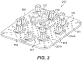
- the plate 100 can also include a plurality of artifact alignment apertures 103 defined in the plate body 101 and arranged in a predetermined pattern (e.g., a grid) to allow a predetermined mounting arrangement of one or more artifacts (e.g., artifacts 204a, 204b as shown in Figs. 2 , 3A , and 3B ).
- the artifact alignment apertures 103 are configured to allow an artifact to be mounted to the plate body 101.
- the plurality of artifact alignment apertures 103 can include one or more dowel pin holes or any other suitable aperture (e.g., threaded or unthreaded) configured to receive a fastener and/or an attachment portion of an artifact 204a, 204b.
- the predetermined pattern of the artifact alignment apertures 103 can include a plurality of rows and columns as shown. Any other suitable pattern is contemplated herein.
- the plate 100 can include position indices 105 on a surface of the plate body 101.
- the position indices 105 can be associated with at least one of the plurality of rows and/or columns as shown.
- the position indices 105 can include a plurality of letters for one of the plurality of rows or columns (e.g., rows as shown), and a plurality of numbers for the other of the plurality of rows or columns (e.g., columns as shown).
- the indices 105 associated with the pattern e.g., the grid as shown
- the plate 100 can include a plurality of mounting apertures 107 (e.g., threaded and/or any other suitable type of aperture) disposed in the plate body 101 and configured to allow mounting of one or more holding fixtures 209 (e.g., as shown in Fig. 2 ) and/or parts 211.
- the one or more of the plurality of mounting apertures 107 can be the same as or different from the alignment artifact apertures 103.
- the mounting apertures 107 can be disposed in a similar pattern as the alignment artifact apertures 103, but interspersed therebetween.
- the plate 100 can include one or more device attachment apertures 108 configured to allow the plate 100 to be attached to a 3D scanning machine (e.g., as shown in Figs. 4A-4C ).
- a 3D scanning system 200 can include a plate 100 as described above.
- the system 200 can further include one or more artifacts 204a, 204b, e.g., attached to the plate body 101 (e.g., with pins, screws, glue, and/or any other suitable fastening method/device).
- the system 200 can also include one or more holding fixtures 209 configured to hold a part 211 to the plate 100 during scanning.
- the one or more holding fixtures 209 can include any suitable shape, size, and/or mounting arrangement to allow the holding fixture 209 to hold one or more parts 211.
- the holding fixture 209 can be adjustable to fit to any suitable part shape and/or size.
- At least one of the one or more artifacts 204a, 204b can include an artifact body 213a, 213b and a mounting flange 215.
- the mounting flange can include one or more mounting holes 216 configured to align with the alignment artifact apertures 103 and to allow mounting thereto using a suitable fastener and/or method as described above.
- the artifact body 213a, 213b can include a multi-sided post (e.g., an octagonal post or any other suitable number of sides). Any other suitable shape (e.g., cylindrical), size, and/or features are contemplated herein for one or more of the artifacts 204a, 204b.
- One or more artifacts 204a, 204b can be made from aluminum or any other suitable material (e.g., to be light weight).
- One or more of the artifacts 204a, 204b can be anodized a particular color (e.g., black) which can cause the one or more artifacts 204a, 204b to not show in the scan data.
- At least one of the one or more artifacts 204a, 204b can include a frustum tip 217.
- the frustum tip 217 can include an octagonal frustum.
- at least one of the one or more artifacts 204a, 204b can include a mirrored frustum 219 defined in the artifact body 213b.
- the frustum tip 217 and/or the mirrored frustum 219 define a plurality of faces 221 that can be used to help a scanning device determine an orientation of the system 200 relative to the imagine device.
- the one or more artifacts 204a, 204b can include an imaging target 223 (e.g., a sticker, a painted target) configured to allow imaging software to determine an orientation of the part 211 as a function of each imaging target 223 on each artifact 204a, 204b.
- the imaging target 223 can be any suitable target (e.g., a contrasted dot on face 221 as shown) as appreciated by one having ordinary skill in the art in view of this disclosure.
- each artifact 204a, 204b on a plate 100 can include at least one imaging target 223.
- each face 221 and/or other suitable surface of each artifact 204a, 204b can include at least one imaging target 223.
- a plurality of targets 223 can be placed on artifacts 204a, 204b in random configurations. These targets 223 can be used by the scanner to mesh scan data together to create a scan of the entire desired part or feature as appreciated by those having ordinary skill in the art.
- a scanning device 400 including an embodiment of a plate 100 attached thereto.
- One or more parts mounted to a plate 100 can be moved into different orientations and scanned multiple times. Then, all scans can be meshed together to create a representation of the entire part.
- the scanning device 400 can move the plate (e.g., in an automated fashion) by tilting and rotating to achieve the required view for the camera. Any suitable embodiment of a plate 100 and/or system 200 as described above can be attached to the device 400.
- a method for creating a 3D image of a part can include placing one or more artifacts (e.g., artifacts 204a, 204b) on a plate (e.g., plate 100), and mounting a part (e.g., part 211) to the plate in a predetermined location relative to the one or more artifacts.
- Placing the one or more artifacts and/or mounting the part can include using and/or recording indices (e.g., indices 105) on the plate that indicate a position of the one or more artifacts and/or the part.
- embodiments can include one or more interchangeable artifacts containing targets that can be used by the scanner for scan-to-scan matching. These artifacts can be moved around into different configurations based on what is being scanned.
- one or more standard scanning programs can be created and/or utilized that will provide basic scan results without having to create a distinct program for each piece of prototype hardware, for example.
- One or more general holding fixtures can be created to hold multiple parts for scanning and can be moved to different locations on the fixture as well to accommodate different part configurations.
- Embodiments include targets that can be placed on the faces of the artifacts in order to make them visible to the scanner from many different orientations, for example. The scanner software can see these target dots (e.g., white dots contrasted on black), to understand orientation and to know how to stitch the images together to make a 3D image.
- Embodiments as described above make scan-to-scan matching and setup more efficient.
- Embodiments of the holding fixture can be easily changed to accommodate different parts and can use a basic program to obtain scan data quickly without the need for making a new program for each part.
- setting artifacts and/or fixtures/parts up in a predetermined way on a grid allows repeatable set up for similar parts and stops the need to create software to interpret each type of device.
Landscapes
- Physics & Mathematics (AREA)
- General Physics & Mathematics (AREA)
- Engineering & Computer Science (AREA)
- Multimedia (AREA)
- Signal Processing (AREA)
- Dental Tools And Instruments Or Auxiliary Dental Instruments (AREA)
- Length Measuring Devices By Optical Means (AREA)
Abstract
Description
- The present disclosure relates to scanning systems, more specifically to 3D scanning systems.
- An optical 3D scanner is used to scan piece parts and check for non-conformances on prototype parts, for example. Existing systems force the user of the scanning machine to change the setup for each part which is time consuming and challenging considering the variation in the parts. For example, each different part requires creating a new fixture or way of holding the part and a new program for operation of the machine. In certain cases, some parts lack unique features that are needed for scan to scan matching. Currently, various ways are used to hold these parts, e.g., hot glue, gage vises, clamps, custom fixtures, etc., as the existing machines comes equipped only with a simple flat plate with a grid of threaded mounting holes.
- Such conventional methods and systems have generally been considered satisfactory for their intended purpose. However, there is still a need in the art for improved scanning systems. The present disclosure provides a solution for this need.
- A plate for a 3D scanning system can include a plate body configured to mount to a 3D scanning system, and a plurality of artifact alignment apertures defined in the plate body arranged in a predetermined pattern to allow a predetermined mounting arrangement of one or more artifacts. The artifact alignment apertures are configured to allow an artifact to be mounted to the plate body.
- The predetermined pattern can include a plurality of rows and columns. The plate can include position indices on a surface of the plate body and associated with at least one of the plurality of rows and/or columns. The position indices can include a plurality of letters for one of the plurality of rows or columns, and a plurality of numbers for the other of the plurality of rows or columns.
- The plate can further include a plurality of mounting apertures disposed in the plate body configured to allow mounting of one or more holding fixtures and/or parts. The plate can further include one or more artifacts attached to the plate body.
- In accordance with at least one aspect of this disclosure, a 3D scanning system can include a plate as described above. The system can further include one or more artifacts, e.g., attached to the plate body.
- At least one of the one or more artifacts can include an artifact body and a mounting flange. In certain embodiments, the artifact body can include a multi-sided post. Any suitable shape, size, and/or features are contemplated herein for one or more of the artifacts.
- In certain embodiments, at least one of the one or more artifacts can include a frustum tip. For example, the frustum tip can include an octagonal frustum. In certain embodiments, at least one of the one or more artifacts can include a mirrored frustum defined in the artifact body. The one or more artifacts can include an imaging target (e.g., a sticker, a painted target) configured to allow imaging software to determine an orientation of the part as a function of each imaging target on each artifact.
- In accordance with at least one aspect of this disclosure, a method for creating a 3D image of a part can include placing one or more artifacts on a plate, and mounting a part to the plate in a predetermined location relative to the one or more artifacts. Placing the one or more artifacts and/or mounting the part can include using and/or recording indices on the plate that indicate a position of the one or more artifacts and/or the part.
- These and other features of the systems and methods of the subject disclosure will become more readily apparent to those skilled in the art from the following detailed description taken in conjunction with the drawings.
- So that those skilled in the art to which the subject disclosure appertains will readily understand how to make and use the devices and methods of the subject disclosure without undue experimentation, embodiments thereof will be described in detail herein below with reference to certain figures, wherein:
-
Fig. 1 is a perspective view of an embodiment of a plate in accordance with this disclosure; -
Fig. 2 is a perspective view of an embodiment of a system in accordance with this disclosure, shown utilizing the plate ofFig. 1 and having an embodiment of a part mounted thereto; -
Fig. 3A is a perspective view of an embodiment of an artifact in accordance with this disclosure; -
Fig. 3B is a perspective view of an embodiment of an artifact in accordance with this disclosure; -
Figs. 4A-4C are diagrams of various views of an embodiment of a 3D scanning system, shown utilizing the plate ofFig. 1 and indicating various directions of motion of the plate relative to the view of the imaging device. - Reference will now be made to the drawings wherein like reference numerals identify similar structural features or aspects of the subject disclosure. For purposes of explanation and illustration, and not limitation, an illustrative view of an embodiment of a plate in accordance with the disclosure is shown in
Fig. 1 and is designated generally byreference character 100. Other embodiments and/or aspects of this disclosure are shown inFigs. 2-4C . The systems and methods described herein can be used to simplify 3D imaging of parts. - Referring to
Fig. 1 , aplate 100 for a 3D scanning system (e.g., as shown inFigs. 4A-4C ) can include aplate body 101 configured to mount to a 3D scanning system. Theplate 100 can also include a plurality ofartifact alignment apertures 103 defined in theplate body 101 and arranged in a predetermined pattern (e.g., a grid) to allow a predetermined mounting arrangement of one or more artifacts (e.g.,artifacts Figs. 2 ,3A , and3B ). - Referring additionally to
Fig. 2 , theartifact alignment apertures 103 are configured to allow an artifact to be mounted to theplate body 101. For example, the plurality ofartifact alignment apertures 103 can include one or more dowel pin holes or any other suitable aperture (e.g., threaded or unthreaded) configured to receive a fastener and/or an attachment portion of anartifact artifact alignment apertures 103 can include a plurality of rows and columns as shown. Any other suitable pattern is contemplated herein. - The
plate 100 can includeposition indices 105 on a surface of theplate body 101. Theposition indices 105 can be associated with at least one of the plurality of rows and/or columns as shown. In certain embodiments, theposition indices 105 can include a plurality of letters for one of the plurality of rows or columns (e.g., rows as shown), and a plurality of numbers for the other of the plurality of rows or columns (e.g., columns as shown). Theindices 105 associated with the pattern (e.g., the grid as shown) can be used so that successful set-ups relating to specific parts can be recorded so they can be repeated at a later date if needed, for example. - In certain embodiments, the
plate 100 can include a plurality of mounting apertures 107 (e.g., threaded and/or any other suitable type of aperture) disposed in theplate body 101 and configured to allow mounting of one or more holding fixtures 209 (e.g., as shown inFig. 2 ) and/orparts 211. The one or more of the plurality ofmounting apertures 107 can be the same as or different from thealignment artifact apertures 103. As shown, in certain embodiments, themounting apertures 107 can be disposed in a similar pattern as thealignment artifact apertures 103, but interspersed therebetween. Theplate 100 can include one or moredevice attachment apertures 108 configured to allow theplate 100 to be attached to a 3D scanning machine (e.g., as shown inFigs. 4A-4C ). - Referring specifically to
Figs. 2 ,3A , and3B , in accordance with at least one aspect of this disclosure, a3D scanning system 200 can include aplate 100 as described above. Thesystem 200 can further include one ormore artifacts - The
system 200 can also include one ormore holding fixtures 209 configured to hold apart 211 to theplate 100 during scanning. The one ormore holding fixtures 209 can include any suitable shape, size, and/or mounting arrangement to allow the holdingfixture 209 to hold one ormore parts 211. The holdingfixture 209 can be adjustable to fit to any suitable part shape and/or size. - At least one of the one or
more artifacts artifact body flange 215. The mounting flange can include one or more mountingholes 216 configured to align with thealignment artifact apertures 103 and to allow mounting thereto using a suitable fastener and/or method as described above. In certain embodiments, as shown, theartifact body artifacts - One or
more artifacts artifacts more artifacts - In certain embodiments, at least one of the one or
more artifacts frustum tip 217. For example, as shown, thefrustum tip 217 can include an octagonal frustum. Referring toFig. 3B , in certain embodiments, at least one of the one ormore artifacts frustum 219 defined in theartifact body 213b. Thefrustum tip 217 and/or the mirroredfrustum 219 define a plurality offaces 221 that can be used to help a scanning device determine an orientation of thesystem 200 relative to the imagine device. - For example, referring to
Fig. 3A , the one ormore artifacts part 211 as a function of eachimaging target 223 on eachartifact imaging target 223 can be any suitable target (e.g., a contrasted dot onface 221 as shown) as appreciated by one having ordinary skill in the art in view of this disclosure. - In certain embodiments, each
artifact plate 100 can include at least oneimaging target 223. In certain embodiments, eachface 221 and/or other suitable surface of eachartifact imaging target 223. In certain embodiments, a plurality oftargets 223 can be placed onartifacts targets 223 can be used by the scanner to mesh scan data together to create a scan of the entire desired part or feature as appreciated by those having ordinary skill in the art. - Referring to
Figs. 4A-4C , ascanning device 400 is shown including an embodiment of aplate 100 attached thereto. One or more parts mounted to aplate 100 can be moved into different orientations and scanned multiple times. Then, all scans can be meshed together to create a representation of the entire part. As shown, thescanning device 400 can move the plate (e.g., in an automated fashion) by tilting and rotating to achieve the required view for the camera. Any suitable embodiment of aplate 100 and/orsystem 200 as described above can be attached to thedevice 400. - In accordance with at least one aspect of this disclosure, a method for creating a 3D image of a part can include placing one or more artifacts (e.g.,
artifacts - As described above, embodiments can include one or more interchangeable artifacts containing targets that can be used by the scanner for scan-to-scan matching. These artifacts can be moved around into different configurations based on what is being scanned. By using such embodiments, one or more standard scanning programs can be created and/or utilized that will provide basic scan results without having to create a distinct program for each piece of prototype hardware, for example. One or more general holding fixtures can be created to hold multiple parts for scanning and can be moved to different locations on the fixture as well to accommodate different part configurations. Embodiments include targets that can be placed on the faces of the artifacts in order to make them visible to the scanner from many different orientations, for example. The scanner software can see these target dots (e.g., white dots contrasted on black), to understand orientation and to know how to stitch the images together to make a 3D image.
- Embodiments as described above make scan-to-scan matching and setup more efficient. Embodiments of the holding fixture can be easily changed to accommodate different parts and can use a basic program to obtain scan data quickly without the need for making a new program for each part. In certain embodiments, setting artifacts and/or fixtures/parts up in a predetermined way on a grid allows repeatable set up for similar parts and stops the need to create software to interpret each type of device.
- The methods and systems of the present disclosure, as described above and shown in the drawings, provide for scanning systems and methods with superior properties. While the apparatus and methods of the subject disclosure have been shown and described with reference to embodiments, those skilled in the art will readily appreciate that changes and/or modifications may be made thereto without departing from the spirit and scope of the subject disclosure.
Claims (15)
- A plate (100) for a 3D scanning system, comprising:a plate body (101) configured to mount to a 3D scanning system; anda plurality of artifact alignment apertures (103) defined in the plate body (101) arranged in a predetermined pattern to allow a predetermined mounting arrangement of one or more artifacts (104a, 204b), wherein the artifact alignment apertures are configured to allow an artifact to be mounted to the plate body (101).
- The plate of claim 1, wherein the predetermined pattern includes a plurality of rows and columns.
- The plate of claim 2, further comprising position indices on a surface of the plate body (101) and associated with at least one of the plurality of rows and/or columns.
- The plate of claim 3, wherein the position indices include a plurality of letters for one of the plurality of rows or columns, and a plurality of numbers for the other of the plurality of rows or columns.
- The plate of any preceding claim, further comprising a plurality of mounting apertures (107) disposed in the plate body (101) configured to allow mounting of one or more holding fixtures (209) and/or parts.
- The plate of any preceding claim, further comprising one or more artifacts (204a, 204b) attached to the plate body (101).
- A 3D scanning system, comprising the plate of any preceding claim.
- The system of claim 7, further comprising one or more artifacts (204a, 204b) attached to the plate body (101).
- The system of claim 8, wherein at least one of the one or more artifacts (204a, 204b) includes an artifact body (213a, 213b) and a mounting flange (215), and preferably wherein the artifact body (213a, 214b) includes a multi-sided post.
- The system of claim 8, wherein at least one of the one or more artifacts includes a frustum tip (217).
- The system of claim 10, wherein the frustum tip (217) comprises an octagonal frustum.
- The system of claim 8, wherein at least one of the one or more artifacts (204a, 204b) include a mirrored frustum defined in the artifact body (213a, 213b).
- The system of claim 8, wherein the one or more artifacts (204a, 204b) include an imaging target (223) configured to allow imaging software to determine an orientation of the part as a function of each imaging target on each artifact (204a, 204b).
- A method for creating a 3D image of a part, comprising:placing one or more artifacts (204a, 204b) on a plate (100); andmounting a part to the plate (100) in a predetermined location relative to the one or more artifacts.
- The method of claim 14, wherein placing the one or more artifacts (204a, 204b) and/or mounting the part includes using and/or recording indices on the plate that indicate a position of the one or more artifacts and/or the part.
Applications Claiming Priority (1)
| Application Number | Priority Date | Filing Date | Title |
|---|---|---|---|
| US15/266,489 US10697756B2 (en) | 2016-09-15 | 2016-09-15 | 3D scanning systems |
Publications (2)
| Publication Number | Publication Date |
|---|---|
| EP3296689A1 true EP3296689A1 (en) | 2018-03-21 |
| EP3296689B1 EP3296689B1 (en) | 2021-12-01 |
Family
ID=60021865
Family Applications (1)
| Application Number | Title | Priority Date | Filing Date |
|---|---|---|---|
| EP17190991.4A Active EP3296689B1 (en) | 2016-09-15 | 2017-09-14 | 3d scanning system |
Country Status (2)
| Country | Link |
|---|---|
| US (1) | US10697756B2 (en) |
| EP (1) | EP3296689B1 (en) |
Families Citing this family (4)
| Publication number | Priority date | Publication date | Assignee | Title |
|---|---|---|---|---|
| JP6631984B1 (en) * | 2019-06-25 | 2020-01-15 | 株式会社浅沼技研 | Inspection master |
| US11703311B1 (en) * | 2022-01-27 | 2023-07-18 | Hexagon Metrology, Inc. | Fixture-assembling system |
| US20240017490A1 (en) * | 2022-07-15 | 2024-01-18 | Relativity Space, Inc. | Modular Metal 3-D Printer Build Plate |
| WO2026120645A1 (en) * | 2024-12-06 | 2026-06-11 | Technè S.R.L. | Support jigs for objects to be tested |
Citations (3)
| Publication number | Priority date | Publication date | Assignee | Title |
|---|---|---|---|---|
| US4364182A (en) * | 1981-05-12 | 1982-12-21 | The United States Of America As Represented By The United States Department Of Energy | Latin square three dimensional gage master |
| US5193286A (en) * | 1992-04-21 | 1993-03-16 | Collier Kevin E | Modular gage |
| US20060026852A1 (en) * | 2004-08-09 | 2006-02-09 | Mitutoyo Corporation | Reference coordinate calculating method, reference coordinate calculating program, recording medium thereof, reference plate and form measuring machine |
Family Cites Families (17)
| Publication number | Priority date | Publication date | Assignee | Title |
|---|---|---|---|---|
| US3732722A (en) * | 1971-08-20 | 1973-05-15 | Perkin Elmer Corp | Material holder |
| US3798792A (en) * | 1971-11-22 | 1974-03-26 | J Askew | Educational word-forming method and device |
| US5107599A (en) * | 1990-08-28 | 1992-04-28 | General Motors Corporation | Universal fixture for coordinate measuring machines |
| JPH0798329A (en) * | 1993-09-28 | 1995-04-11 | Hamamatsu Photonics Kk | EO probe |
| US5735056A (en) * | 1995-10-03 | 1998-04-07 | Gosine; Gary G. | Modular tooling system for use with a gauging machine |
| US20050218280A1 (en) * | 2003-12-02 | 2005-10-06 | Ralph Rojas | Scanner plate hook and hook back plate for perforated boards |
| US7557910B2 (en) * | 2004-12-19 | 2009-07-07 | Kla-Tencor Corporation | System and method for controlling a beam source in a workpiece surface inspection system |
| US7394151B2 (en) * | 2005-02-15 | 2008-07-01 | Alpha & Omega Semiconductor Limited | Semiconductor package with plated connection |
| WO2006094409A1 (en) * | 2005-03-11 | 2006-09-14 | Creaform Inc. | Auto-referenced system and apparatus for three-dimensional scanning |
| US7113878B1 (en) * | 2005-05-18 | 2006-09-26 | Perceptron, Inc. | Target for calibrating a non-contact sensor |
| US7783007B2 (en) * | 2006-07-27 | 2010-08-24 | Deutsches Krebsforschungszentrum Stiftung des öeffentlichen Rechts | Irradiation device and collimator |
| US7854071B2 (en) * | 2007-03-30 | 2010-12-21 | The Hong Kong University Of Science And Technology | Customized shoe and insole, method and apparatus for determining shape of a foot and for making a shoe or insole |
| US7869026B2 (en) * | 2007-12-21 | 2011-01-11 | United Technologies Corp. | Targeted artifacts and methods for evaluating 3-D coordinate system measurement accuracy of optical 3-D measuring systems using such targeted artifacts |
| JP6373007B2 (en) * | 2011-02-02 | 2018-08-15 | スリーエム イノベイティブ プロパティズ カンパニー | NOZZLE AND METHOD FOR PRODUCING NOZZLE |
| US9372160B2 (en) * | 2011-05-17 | 2016-06-21 | Gii Acquisition, Llc | Method and system for optically inspecting the ends of a manufactured part at a single inspection station having a measurement axis |
| US20130278725A1 (en) * | 2012-04-24 | 2013-10-24 | Connecticut Center for Advanced Technology, Inc. | Integrated Structured Light 3D Scanner |
| US9998729B2 (en) * | 2014-12-12 | 2018-06-12 | Ryan Lilien | Method and system for three dimensional imaging and analysis |
-
2016
- 2016-09-15 US US15/266,489 patent/US10697756B2/en active Active
-
2017
- 2017-09-14 EP EP17190991.4A patent/EP3296689B1/en active Active
Patent Citations (3)
| Publication number | Priority date | Publication date | Assignee | Title |
|---|---|---|---|---|
| US4364182A (en) * | 1981-05-12 | 1982-12-21 | The United States Of America As Represented By The United States Department Of Energy | Latin square three dimensional gage master |
| US5193286A (en) * | 1992-04-21 | 1993-03-16 | Collier Kevin E | Modular gage |
| US20060026852A1 (en) * | 2004-08-09 | 2006-02-09 | Mitutoyo Corporation | Reference coordinate calculating method, reference coordinate calculating program, recording medium thereof, reference plate and form measuring machine |
Also Published As
| Publication number | Publication date |
|---|---|
| US20180073859A1 (en) | 2018-03-15 |
| US10697756B2 (en) | 2020-06-30 |
| EP3296689B1 (en) | 2021-12-01 |
Similar Documents
| Publication | Publication Date | Title |
|---|---|---|
| EP3296689B1 (en) | 3d scanning system | |
| EP2071279B1 (en) | Method and device for recording measurements of bodies and contour data of a solid body | |
| DE102008023264B4 (en) | Method for flexible detection of the geometric shape of objects with optical 3D measuring technology | |
| EP3611497B1 (en) | Inspection apparatus for inspecting a cable tip of a cable and method for cleaning the mirror of an inspection apparatus | |
| DE112006002529T5 (en) | Three-point sighting alignment system with a single camera for a device handling device | |
| DE102014209471A1 (en) | Structured illumination projection with improved exposure control | |
| DE112015001549T5 (en) | Test system and test method | |
| US11551419B2 (en) | Method of generating three-dimensional model, training data, machine learning model, and system | |
| DE112015001561T5 (en) | Test system and test method | |
| DE102014217598A1 (en) | Method and arrangement for acquiring acoustic and optical information and a corresponding computer program and a corresponding computer-readable storage medium | |
| JP2017110991A (en) | Measurement system, measurement method, robot control method, robot, robot system, and picking device | |
| US9535257B2 (en) | Multiple collimator unit | |
| DE102015205616A1 (en) | Optical coordinate measuring device | |
| DE112016003188T5 (en) | Three-dimensional measuring device | |
| JP2019517002A (en) | Three-dimensional calibration tool and method | |
| DE102015220931A1 (en) | Method and device for checking the refractive power distribution and the centering | |
| DE102012103980A1 (en) | Method for aligning component e.g. tailgate in predetermined desired position of vehicle, involves determining positional deviation of component based on actual position of fixed features of component and desired position | |
| EP3701330A1 (en) | System and method for optical inspection of an object | |
| WO2018197078A1 (en) | Inspection apparatus for optically inspecting an object, production plant having the inspection apparatus, and method for optically inspecting the object using the inspection apparatus | |
| DE102010007396A1 (en) | Method and device for optically inspecting a device under test with an at least partially reflecting surface | |
| DE102022117469A1 (en) | Product Testing System and Procedures | |
| KR101816781B1 (en) | 3D scanner using photogrammetry and photogrammetry photographing for high-quality input data of 3D modeling | |
| EP3048456B1 (en) | Method for locating of grip points of objects | |
| US20100207945A1 (en) | Template for creating sequin-based designs & methods of use thereof | |
| EP2876880A1 (en) | Camera test apparatus |
Legal Events
| Date | Code | Title | Description |
|---|---|---|---|
| PUAI | Public reference made under article 153(3) epc to a published international application that has entered the european phase |
Free format text: ORIGINAL CODE: 0009012 |
|
| STAA | Information on the status of an ep patent application or granted ep patent |
Free format text: STATUS: THE APPLICATION HAS BEEN PUBLISHED |
|
| AK | Designated contracting states |
Kind code of ref document: A1 Designated state(s): AL AT BE BG CH CY CZ DE DK EE ES FI FR GB GR HR HU IE IS IT LI LT LU LV MC MK MT NL NO PL PT RO RS SE SI SK SM TR |
|
| AX | Request for extension of the european patent |
Extension state: BA ME |
|
| STAA | Information on the status of an ep patent application or granted ep patent |
Free format text: STATUS: REQUEST FOR EXAMINATION WAS MADE |
|
| 17P | Request for examination filed |
Effective date: 20180920 |
|
| RBV | Designated contracting states (corrected) |
Designated state(s): AL AT BE BG CH CY CZ DE DK EE ES FI FR GB GR HR HU IE IS IT LI LT LU LV MC MK MT NL NO PL PT RO RS SE SI SK SM TR |
|
| STAA | Information on the status of an ep patent application or granted ep patent |
Free format text: STATUS: EXAMINATION IS IN PROGRESS |
|
| 17Q | First examination report despatched |
Effective date: 20181026 |
|
| GRAP | Despatch of communication of intention to grant a patent |
Free format text: ORIGINAL CODE: EPIDOSNIGR1 |
|
| STAA | Information on the status of an ep patent application or granted ep patent |
Free format text: STATUS: GRANT OF PATENT IS INTENDED |
|
| INTG | Intention to grant announced |
Effective date: 20210628 |
|
| GRAS | Grant fee paid |
Free format text: ORIGINAL CODE: EPIDOSNIGR3 |
|
| GRAA | (expected) grant |
Free format text: ORIGINAL CODE: 0009210 |
|
| STAA | Information on the status of an ep patent application or granted ep patent |
Free format text: STATUS: THE PATENT HAS BEEN GRANTED |
|
| AK | Designated contracting states |
Kind code of ref document: B1 Designated state(s): AL AT BE BG CH CY CZ DE DK EE ES FI FR GB GR HR HU IE IS IT LI LT LU LV MC MK MT NL NO PL PT RO RS SE SI SK SM TR |
|
| REG | Reference to a national code |
Ref country code: GB Ref legal event code: FG4D |
|
| REG | Reference to a national code |
Ref country code: AT Ref legal event code: REF Ref document number: 1452163 Country of ref document: AT Kind code of ref document: T Effective date: 20211215 Ref country code: CH Ref legal event code: EP |
|
| REG | Reference to a national code |
Ref country code: IE Ref legal event code: FG4D |
|
| REG | Reference to a national code |
Ref country code: DE Ref legal event code: R096 Ref document number: 602017050074 Country of ref document: DE |
|
| REG | Reference to a national code |
Ref country code: LT Ref legal event code: MG9D |
|
| REG | Reference to a national code |
Ref country code: NL Ref legal event code: MP Effective date: 20211201 |
|
| REG | Reference to a national code |
Ref country code: AT Ref legal event code: MK05 Ref document number: 1452163 Country of ref document: AT Kind code of ref document: T Effective date: 20211201 |
|
| PG25 | Lapsed in a contracting state [announced via postgrant information from national office to epo] |
Ref country code: RS Free format text: LAPSE BECAUSE OF FAILURE TO SUBMIT A TRANSLATION OF THE DESCRIPTION OR TO PAY THE FEE WITHIN THE PRESCRIBED TIME-LIMIT Effective date: 20211201 Ref country code: LT Free format text: LAPSE BECAUSE OF FAILURE TO SUBMIT A TRANSLATION OF THE DESCRIPTION OR TO PAY THE FEE WITHIN THE PRESCRIBED TIME-LIMIT Effective date: 20211201 Ref country code: FI Free format text: LAPSE BECAUSE OF FAILURE TO SUBMIT A TRANSLATION OF THE DESCRIPTION OR TO PAY THE FEE WITHIN THE PRESCRIBED TIME-LIMIT Effective date: 20211201 Ref country code: BG Free format text: LAPSE BECAUSE OF FAILURE TO SUBMIT A TRANSLATION OF THE DESCRIPTION OR TO PAY THE FEE WITHIN THE PRESCRIBED TIME-LIMIT Effective date: 20220301 Ref country code: AT Free format text: LAPSE BECAUSE OF FAILURE TO SUBMIT A TRANSLATION OF THE DESCRIPTION OR TO PAY THE FEE WITHIN THE PRESCRIBED TIME-LIMIT Effective date: 20211201 |
|
| RAP4 | Party data changed (patent owner data changed or rights of a patent transferred) |
Owner name: COLLINS ENGINE NOZZLES, INC. |
|
| PG25 | Lapsed in a contracting state [announced via postgrant information from national office to epo] |
Ref country code: SE Free format text: LAPSE BECAUSE OF FAILURE TO SUBMIT A TRANSLATION OF THE DESCRIPTION OR TO PAY THE FEE WITHIN THE PRESCRIBED TIME-LIMIT Effective date: 20211201 Ref country code: PL Free format text: LAPSE BECAUSE OF FAILURE TO SUBMIT A TRANSLATION OF THE DESCRIPTION OR TO PAY THE FEE WITHIN THE PRESCRIBED TIME-LIMIT Effective date: 20211201 Ref country code: NO Free format text: LAPSE BECAUSE OF FAILURE TO SUBMIT A TRANSLATION OF THE DESCRIPTION OR TO PAY THE FEE WITHIN THE PRESCRIBED TIME-LIMIT Effective date: 20220301 Ref country code: LV Free format text: LAPSE BECAUSE OF FAILURE TO SUBMIT A TRANSLATION OF THE DESCRIPTION OR TO PAY THE FEE WITHIN THE PRESCRIBED TIME-LIMIT Effective date: 20211201 Ref country code: HR Free format text: LAPSE BECAUSE OF FAILURE TO SUBMIT A TRANSLATION OF THE DESCRIPTION OR TO PAY THE FEE WITHIN THE PRESCRIBED TIME-LIMIT Effective date: 20211201 Ref country code: GR Free format text: LAPSE BECAUSE OF FAILURE TO SUBMIT A TRANSLATION OF THE DESCRIPTION OR TO PAY THE FEE WITHIN THE PRESCRIBED TIME-LIMIT Effective date: 20220302 Ref country code: ES Free format text: LAPSE BECAUSE OF FAILURE TO SUBMIT A TRANSLATION OF THE DESCRIPTION OR TO PAY THE FEE WITHIN THE PRESCRIBED TIME-LIMIT Effective date: 20211201 |
|
| PG25 | Lapsed in a contracting state [announced via postgrant information from national office to epo] |
Ref country code: NL Free format text: LAPSE BECAUSE OF FAILURE TO SUBMIT A TRANSLATION OF THE DESCRIPTION OR TO PAY THE FEE WITHIN THE PRESCRIBED TIME-LIMIT Effective date: 20211201 |
|
| PG25 | Lapsed in a contracting state [announced via postgrant information from national office to epo] |
Ref country code: SM Free format text: LAPSE BECAUSE OF FAILURE TO SUBMIT A TRANSLATION OF THE DESCRIPTION OR TO PAY THE FEE WITHIN THE PRESCRIBED TIME-LIMIT Effective date: 20211201 Ref country code: SK Free format text: LAPSE BECAUSE OF FAILURE TO SUBMIT A TRANSLATION OF THE DESCRIPTION OR TO PAY THE FEE WITHIN THE PRESCRIBED TIME-LIMIT Effective date: 20211201 Ref country code: RO Free format text: LAPSE BECAUSE OF FAILURE TO SUBMIT A TRANSLATION OF THE DESCRIPTION OR TO PAY THE FEE WITHIN THE PRESCRIBED TIME-LIMIT Effective date: 20211201 Ref country code: PT Free format text: LAPSE BECAUSE OF FAILURE TO SUBMIT A TRANSLATION OF THE DESCRIPTION OR TO PAY THE FEE WITHIN THE PRESCRIBED TIME-LIMIT Effective date: 20220401 Ref country code: EE Free format text: LAPSE BECAUSE OF FAILURE TO SUBMIT A TRANSLATION OF THE DESCRIPTION OR TO PAY THE FEE WITHIN THE PRESCRIBED TIME-LIMIT Effective date: 20211201 Ref country code: CZ Free format text: LAPSE BECAUSE OF FAILURE TO SUBMIT A TRANSLATION OF THE DESCRIPTION OR TO PAY THE FEE WITHIN THE PRESCRIBED TIME-LIMIT Effective date: 20211201 |
|
| REG | Reference to a national code |
Ref country code: DE Ref legal event code: R097 Ref document number: 602017050074 Country of ref document: DE |
|
| PG25 | Lapsed in a contracting state [announced via postgrant information from national office to epo] |
Ref country code: IS Free format text: LAPSE BECAUSE OF FAILURE TO SUBMIT A TRANSLATION OF THE DESCRIPTION OR TO PAY THE FEE WITHIN THE PRESCRIBED TIME-LIMIT Effective date: 20220401 |
|
| PLBE | No opposition filed within time limit |
Free format text: ORIGINAL CODE: 0009261 |
|
| STAA | Information on the status of an ep patent application or granted ep patent |
Free format text: STATUS: NO OPPOSITION FILED WITHIN TIME LIMIT |
|
| PG25 | Lapsed in a contracting state [announced via postgrant information from national office to epo] |
Ref country code: DK Free format text: LAPSE BECAUSE OF FAILURE TO SUBMIT A TRANSLATION OF THE DESCRIPTION OR TO PAY THE FEE WITHIN THE PRESCRIBED TIME-LIMIT Effective date: 20211201 Ref country code: AL Free format text: LAPSE BECAUSE OF FAILURE TO SUBMIT A TRANSLATION OF THE DESCRIPTION OR TO PAY THE FEE WITHIN THE PRESCRIBED TIME-LIMIT Effective date: 20211201 |
|
| 26N | No opposition filed |
Effective date: 20220902 |
|
| PG25 | Lapsed in a contracting state [announced via postgrant information from national office to epo] |
Ref country code: SI Free format text: LAPSE BECAUSE OF FAILURE TO SUBMIT A TRANSLATION OF THE DESCRIPTION OR TO PAY THE FEE WITHIN THE PRESCRIBED TIME-LIMIT Effective date: 20211201 |
|
| PG25 | Lapsed in a contracting state [announced via postgrant information from national office to epo] |
Ref country code: MC Free format text: LAPSE BECAUSE OF FAILURE TO SUBMIT A TRANSLATION OF THE DESCRIPTION OR TO PAY THE FEE WITHIN THE PRESCRIBED TIME-LIMIT Effective date: 20211201 |
|
| REG | Reference to a national code |
Ref country code: CH Ref legal event code: PL |
|
| REG | Reference to a national code |
Ref country code: BE Ref legal event code: MM Effective date: 20220930 |
|
| PG25 | Lapsed in a contracting state [announced via postgrant information from national office to epo] |
Ref country code: IT Free format text: LAPSE BECAUSE OF FAILURE TO SUBMIT A TRANSLATION OF THE DESCRIPTION OR TO PAY THE FEE WITHIN THE PRESCRIBED TIME-LIMIT Effective date: 20211201 |
|
| PG25 | Lapsed in a contracting state [announced via postgrant information from national office to epo] |
Ref country code: LU Free format text: LAPSE BECAUSE OF NON-PAYMENT OF DUE FEES Effective date: 20220914 |
|
| PG25 | Lapsed in a contracting state [announced via postgrant information from national office to epo] |
Ref country code: LI Free format text: LAPSE BECAUSE OF NON-PAYMENT OF DUE FEES Effective date: 20220930 Ref country code: IE Free format text: LAPSE BECAUSE OF NON-PAYMENT OF DUE FEES Effective date: 20220914 Ref country code: CH Free format text: LAPSE BECAUSE OF NON-PAYMENT OF DUE FEES Effective date: 20220930 |
|
| PG25 | Lapsed in a contracting state [announced via postgrant information from national office to epo] |
Ref country code: BE Free format text: LAPSE BECAUSE OF NON-PAYMENT OF DUE FEES Effective date: 20220930 |
|
| PG25 | Lapsed in a contracting state [announced via postgrant information from national office to epo] |
Ref country code: HU Free format text: LAPSE BECAUSE OF FAILURE TO SUBMIT A TRANSLATION OF THE DESCRIPTION OR TO PAY THE FEE WITHIN THE PRESCRIBED TIME-LIMIT; INVALID AB INITIO Effective date: 20170914 |
|
| PG25 | Lapsed in a contracting state [announced via postgrant information from national office to epo] |
Ref country code: CY Free format text: LAPSE BECAUSE OF FAILURE TO SUBMIT A TRANSLATION OF THE DESCRIPTION OR TO PAY THE FEE WITHIN THE PRESCRIBED TIME-LIMIT Effective date: 20211201 |
|
| PG25 | Lapsed in a contracting state [announced via postgrant information from national office to epo] |
Ref country code: MK Free format text: LAPSE BECAUSE OF FAILURE TO SUBMIT A TRANSLATION OF THE DESCRIPTION OR TO PAY THE FEE WITHIN THE PRESCRIBED TIME-LIMIT Effective date: 20211201 |
|
| PG25 | Lapsed in a contracting state [announced via postgrant information from national office to epo] |
Ref country code: TR Free format text: LAPSE BECAUSE OF FAILURE TO SUBMIT A TRANSLATION OF THE DESCRIPTION OR TO PAY THE FEE WITHIN THE PRESCRIBED TIME-LIMIT Effective date: 20211201 |
|
| PG25 | Lapsed in a contracting state [announced via postgrant information from national office to epo] |
Ref country code: MT Free format text: LAPSE BECAUSE OF FAILURE TO SUBMIT A TRANSLATION OF THE DESCRIPTION OR TO PAY THE FEE WITHIN THE PRESCRIBED TIME-LIMIT Effective date: 20211201 |
|
| PGFP | Annual fee paid to national office [announced via postgrant information from national office to epo] |
Ref country code: DE Payment date: 20250820 Year of fee payment: 9 |
|
| PGFP | Annual fee paid to national office [announced via postgrant information from national office to epo] |
Ref country code: GB Payment date: 20250822 Year of fee payment: 9 |
|
| PGFP | Annual fee paid to national office [announced via postgrant information from national office to epo] |
Ref country code: FR Payment date: 20250820 Year of fee payment: 9 |
|
| P01 | Opt-out of the competence of the unified patent court (upc) registered |
Free format text: CASE NUMBER: UPC_APP_0017270_3296689/2025 Effective date: 20251211 |