EP3296686A1 - Tri-axial capacitance probe with case integrated housing - Google Patents
Tri-axial capacitance probe with case integrated housing Download PDFInfo
- Publication number
- EP3296686A1 EP3296686A1 EP17191548.1A EP17191548A EP3296686A1 EP 3296686 A1 EP3296686 A1 EP 3296686A1 EP 17191548 A EP17191548 A EP 17191548A EP 3296686 A1 EP3296686 A1 EP 3296686A1
- Authority
- EP
- European Patent Office
- Prior art keywords
- tri
- conductor member
- axial
- capacitance probe
- wall
- Prior art date
- Legal status (The legal status is an assumption and is not a legal conclusion. Google has not performed a legal analysis and makes no representation as to the accuracy of the status listed.)
- Granted
Links
Images




Classifications
-
- G—PHYSICS
- G01—MEASURING; TESTING
- G01B—MEASURING LENGTH, THICKNESS OR SIMILAR LINEAR DIMENSIONS; MEASURING ANGLES; MEASURING AREAS; MEASURING IRREGULARITIES OF SURFACES OR CONTOURS
- G01B7/00—Measuring arrangements characterised by the use of electric or magnetic techniques
- G01B7/14—Measuring arrangements characterised by the use of electric or magnetic techniques for measuring distance or clearance between spaced objects or spaced apertures
-
- F—MECHANICAL ENGINEERING; LIGHTING; HEATING; WEAPONS; BLASTING
- F01—MACHINES OR ENGINES IN GENERAL; ENGINE PLANTS IN GENERAL; STEAM ENGINES
- F01D—NON-POSITIVE DISPLACEMENT MACHINES OR ENGINES, e.g. STEAM TURBINES
- F01D21/00—Shutting-down of machines or engines, e.g. in emergency; Regulating, controlling, or safety means not otherwise provided for
- F01D21/003—Arrangements for testing or measuring
-
- F—MECHANICAL ENGINEERING; LIGHTING; HEATING; WEAPONS; BLASTING
- F01—MACHINES OR ENGINES IN GENERAL; ENGINE PLANTS IN GENERAL; STEAM ENGINES
- F01D—NON-POSITIVE DISPLACEMENT MACHINES OR ENGINES, e.g. STEAM TURBINES
- F01D25/00—Component parts, details, or accessories, not provided for in, or of interest apart from, other groups
- F01D25/24—Casings; Casing parts, e.g. diaphragms, casing fastenings
-
- F—MECHANICAL ENGINEERING; LIGHTING; HEATING; WEAPONS; BLASTING
- F01—MACHINES OR ENGINES IN GENERAL; ENGINE PLANTS IN GENERAL; STEAM ENGINES
- F01D—NON-POSITIVE DISPLACEMENT MACHINES OR ENGINES, e.g. STEAM TURBINES
- F01D5/00—Blades; Blade-carrying members; Heating, heat-insulating, cooling or antivibration means on the blades or the members
- F01D5/02—Blade-carrying members, e.g. rotors
-
- F—MECHANICAL ENGINEERING; LIGHTING; HEATING; WEAPONS; BLASTING
- F04—POSITIVE - DISPLACEMENT MACHINES FOR LIQUIDS; PUMPS FOR LIQUIDS OR ELASTIC FLUIDS
- F04D—NON-POSITIVE-DISPLACEMENT PUMPS
- F04D27/00—Control, e.g. regulation, of pumps, pumping installations or pumping systems specially adapted for elastic fluids
- F04D27/001—Testing thereof; Determination or simulation of flow characteristics; Stall or surge detection, e.g. condition monitoring
-
- F—MECHANICAL ENGINEERING; LIGHTING; HEATING; WEAPONS; BLASTING
- F04—POSITIVE - DISPLACEMENT MACHINES FOR LIQUIDS; PUMPS FOR LIQUIDS OR ELASTIC FLUIDS
- F04D—NON-POSITIVE-DISPLACEMENT PUMPS
- F04D29/00—Details, component parts, or accessories
- F04D29/26—Rotors specially for elastic fluids
- F04D29/32—Rotors specially for elastic fluids for axial flow pumps
- F04D29/321—Rotors specially for elastic fluids for axial flow pumps for axial flow compressors
-
- F—MECHANICAL ENGINEERING; LIGHTING; HEATING; WEAPONS; BLASTING
- F04—POSITIVE - DISPLACEMENT MACHINES FOR LIQUIDS; PUMPS FOR LIQUIDS OR ELASTIC FLUIDS
- F04D—NON-POSITIVE-DISPLACEMENT PUMPS
- F04D29/00—Details, component parts, or accessories
- F04D29/26—Rotors specially for elastic fluids
- F04D29/32—Rotors specially for elastic fluids for axial flow pumps
- F04D29/325—Rotors specially for elastic fluids for axial flow pumps for axial flow fans
-
- F—MECHANICAL ENGINEERING; LIGHTING; HEATING; WEAPONS; BLASTING
- F04—POSITIVE - DISPLACEMENT MACHINES FOR LIQUIDS; PUMPS FOR LIQUIDS OR ELASTIC FLUIDS
- F04D—NON-POSITIVE-DISPLACEMENT PUMPS
- F04D29/00—Details, component parts, or accessories
- F04D29/40—Casings; Connections of working fluid
- F04D29/52—Casings; Connections of working fluid for axial pumps
- F04D29/522—Casings; Connections of working fluid for axial pumps especially adapted for elastic fluid pumps
-
- G—PHYSICS
- G01—MEASURING; TESTING
- G01M—TESTING STATIC OR DYNAMIC BALANCE OF MACHINES OR STRUCTURES; TESTING OF STRUCTURES OR APPARATUS, NOT OTHERWISE PROVIDED FOR
- G01M15/00—Testing of engines
- G01M15/14—Testing gas-turbine engines or jet-propulsion engines
-
- F—MECHANICAL ENGINEERING; LIGHTING; HEATING; WEAPONS; BLASTING
- F05—INDEXING SCHEMES RELATING TO ENGINES OR PUMPS IN VARIOUS SUBCLASSES OF CLASSES F01-F04
- F05D—INDEXING SCHEME FOR ASPECTS RELATING TO NON-POSITIVE-DISPLACEMENT MACHINES OR ENGINES, GAS-TURBINES OR JET-PROPULSION PLANTS
- F05D2220/00—Application
- F05D2220/30—Application in turbines
- F05D2220/32—Application in turbines in gas turbines
Definitions
- This disclosure relates generally to a capacitance probe and a method for assembling a capacitance probe.
- a method involving a wall configured to circumscribe and be radially adjacent a rotor.
- This method includes: providing a tri-axial capacitance probe including a tri-axial conduit that includes an outer conductor member, the tri-axial capacitance probe configured to output data indicative of a characteristic of the rotor; and configuring the tri-axial capacitance probe within a wall aperture in the wall, where the outer conductor member is electrically coupled with the wall, and the wall is configured as a housing for the tri-axial capacitance probe.
- an assembly for rotational equipment.
- This assembly includes a rotor and a wall circumscribing and radially adjacent the rotor.
- the assembly also includes a tri-axial capacitance probe within an aperture in the wall.
- the tri-axial capacitance probe is configured to output data indicative of a characteristic of the rotor.
- the tri-axial capacitance probe includes a tri-axial conduit that includes a tubular outer conductor member directly electrically coupled with the wall.
- the rotational equipment may be configured as a gas turbine engine.
- the providing the tri-axial capacitance probe may include: assembling the tri-axial capacitance probe in a fixture, where the fixture is configured as a temporary housing for the tri-axial capacitance probe; and removing the tri-axial capacitance probe from the fixture, for example, as a module without a housing.
- the providing the tri-axial capacitance probe may include: mating the tri-axial conduit with a fixture aperture extending through a fixture; and temporarily bonding the outer conductor member to the fixture.
- the providing the tri-axial capacitance probe may include: abutting an annular outer insulator against and bonding the outer insulator to the outer conductor member using non-conductive material; and temporarily bonding the outer insulator to the fixture within a counterbore of the fixture aperture.
- An intermediate conductor member of the tri-axial conduit may project into the outer insulator.
- An inner conductor member of the tri-axial conduit may project through the outer insulator.
- the providing the tri-axial capacitance probe may include: nesting an annular guard within and bonding the guard to the outer insulator using non-conductive material; and electrically coupling the guard with the intermediate conductor member.
- the providing the tri-axial capacitance probe may include: nesting an annular inner insulator within and bonding the inner insulator to the guard using non-conductive material.
- the inner conductor member may project through the inner insulator.
- Non-conductive material may be included and axially between the inner insulator and intermediate conductor member.
- the providing the tri-axial capacitance probe may include: nesting a sensor within and bonding the sensor to the inner insulator using non-conductive material; and electrically coupling the sensor with the inner conductor member.
- the sensor may be configured as or otherwise include an annular sensor plate.
- the inner conductor member may project through the sensor plate.
- the providing the tri-axial capacitance probe may include: removing a portion of the inner conductor member that projects out from the sensor plate.
- the providing the tri-axial capacitance probe may include: breaking the temporary bond between the outer conductor member and the fixture and between the outer insulator and the fixture; and removing the tri-axial capacitance probe from the fixture as a module.
- the configuring the tri-axial capacitance probe within the wall may include: bonding the outer conductor member to the wall with conductive material; and/or bonding the outer insulator to the wall with non-conductive material.
- the tri-axial conduit may include an intermediate conductor member and an inner conductor member.
- the intermediate conductor member may be coaxial with, between and electrically isolated from the outer conductor member and the inner conductor member.
- the tri-axial capacitance probe may include a sensor assembly nested in a counterbore in the wall.
- the sensor assembly may include a sensor and an annular guard.
- the sensor may be electrically coupled with the inner conductor member.
- the guard may be electrically coupled with the intermediate conductor member.
- the guard may be between and electrically isolated from the wall and the sensor.
- the sensor assembly may include an annular outer insulator and an annular inner insulator.
- the outer insulator may be between and bonded to the wall and the guard.
- the inner insulator may be between and bonded to the guard and the sensor.
- the tri-axial conduit may include a tubular intermediate conductor member and an inner conductor member.
- the intermediate conductor member may be coaxial with, between and electrically isolated from the outer conductor member and the inner conductor member.
- the wall may be configured as a housing for the tri-axial capacitance probe.
- the wall may include metal support structure and a ceramic coating radially between the metal support structure and the rotor.
- the outer conductor member may be directly electrically coupled with the metal support structure.
- the rotor may include a rotor disk and a plurality of rotor blades arranged circumferentially around the rotor disk in an annular array.
- the tri-axial capacitance probe may be configured to provide data indicative of a radial clearance between at least one of the rotor blades and the wall.
- FIG. 1 illustrates a system 10 for rotational equipment.
- the rotational equipment may be configured and is described below for ease of description as a gas turbine engine.
- This gas turbine engine may be configured as or included in an aircraft propulsion system, an auxiliary power unit (APU), or an industrial gas turbine engine.
- APU auxiliary power unit
- the present disclosure is not limited to such exemplary gas turbine engine applications.
- the system 10 may alternatively be configured for a wind turbine, a water turbine or any other type of equipment (rotational or otherwise) which may include a probe as described below.
- the turbine engine system 10 of FIG. 1 includes a rotor 12, a wall 14 and a sensor system 16.
- the rotor 12 may be configured as a fan rotor, a compressor rotor, a turbine rotor or any other type of rotor included in the gas turbine engine.
- the rotor 12 of FIG. 1 for example, includes at least one rotor disk (not shown) and a plurality of rotor blades 18 (one shown), which are arranged circumferentially around the rotor disk and its rotational axis 20 in an annular array.
- the wall 14 may be configured with a generally tubular full-hoop body.
- the wall 14, for example, extends circumferentially around and axially along the rotational axis 20. The wall 14 thereby circumscribes the rotor 12.
- the wall 14 is also radially adjacent an outer periphery of the rotor 12; e.g., tips 22 of the rotor blades 18.
- the wall 14 of FIG. 1 may be configured as a (e.g., abradable) blade outer air seal, a shroud, a turbine engine case or any other structure that forms a flow path wall within the turbine engine and around the rotor 12.
- the wall 14 of FIG. 1 includes a metal support structure 24 and a ceramic coating 26; e.g., an abradable ceramic coating.
- the metal support structure 24 is configured as a base of and provides structure to the wall 14.
- the ceramic coating 26 is disposed on a radially interior surface 28 of the metal support structure 24.
- the ceramic coating 26 is located radially between the metal support structure 24 and the rotor 12, thereby forming an outer peripheral boundary of a flow path.
- the sensor system 16 includes a controller 30 and one or more tri-axial capacitance probes 32 (one shown).
- the controller 30 may be implemented with a combination of hardware and software.
- the hardware may include a memory and at least one processing device, which may include one or more single-core and/or multi-core processors.
- the hardware may also or alternatively include analog and/or digital circuitry other than that described above.
- the memory is configured to store software (e.g., program instructions) for execution by the processing device, which software execution may control and/or facilitate performance of one or more operations.
- the memory may be configured as a non-transitory computer readable medium.
- Each tri-axial capacitance probe 32 is in signal communication (e.g., hardwired and/or wirelessly coupled) with the controller 30. Each tri-axial capacitance probe 32 is configured to output data to the controller 30 that is indicative of a characteristic of the rotor 12.
- the tri-axial capacitance probe 32 of FIG. 1 is configured to output data indicative of a clearance 34 (e.g., a radial distance) between the rotor 12 and the wall 14. More particularly, the output data indicative of the clearance 34 between the tips 22 of the rotor blades 18 and the ceramic coating 26.
- the output data may also or alternatively be indicative of other rotor characteristics; e.g., rotor speed, a one per revolution signal, etc.
- the tri-axial capacitance probe 32 of FIG. 2 is mated with a wall aperture 36 extending radially through the wall 14.
- This wall aperture 36 includes a bore 38 and a counterbore 40, which extends partially radially into the metal support structure 24 from the interior surface 28 to the bore 38.
- the wall 14 forms a housing for the tri-axial capacitance probe 32. This may enable the tri-axial capacitance probe 32 to take up less space for mounting since it does not require a separate housing to contain the components of the probe 32; e.g., the wall 14 may be the only housing for the probe 32.
- the tri-axial capacitance probe 32 of FIG. 2 includes a tri-axial conduit 42 and a sensor assembly 44.
- the tri-axial conduit 42 is generally arranged within the bore 38.
- the sensor assembly 44 is generally within the counterbore 40.
- the tri-axial conduit 42 includes a tubular outer conductor member 46, a tubular intermediate conductor member 48 and an inner conductor member 50 (e.g., an inner wire).
- the conductor members 46, 48 and 50 are arranged co-axial with one another along a probe axial centerline 52.
- the intermediate conductor member 48 is disposed between, but electrically isolated from, the outer conductor member 46 and the inner conductor member 50.
- a tubular outer insulator member 54 is between the outer conductor member 46 and the intermediate conductor member 48.
- a tubular inner insulator member 56 is between the intermediate conductor member 48 and the inner conductor member 50.
- the outer conductor member 46 is directly electrically coupled with the metal support structure 24 of the wall 14. For example, there may be a tight fit between the outer conductor member 46 and the metal support structure 24.
- the outer conductor member 46 may be bonded to the metal support structure 24 by conductive material; e.g., conductive adhesive material.
- the sensor assembly 44 includes an annular outer insulator 58, an annular guard 60, an annular inner insulator 62 and a sensor 64.
- the outer insulator 58 includes an annular interior rim 66, an annular exterior rim 68 and an annular shelf 70 (e.g., a jog). This shelf 70 connects and extends radially (relative to the probe axial centerline 52) between the interior rim 66 and the exterior rim 68.
- the outer insulator 58 is nested within the wall aperture 36, where the interior rim 66 projects into the bore 38, the exterior rim 68 is within the counterbore 40, and the shelf 70 is abutted axially (relative to the probe axial centerline 52) against the metal support structure 24.
- the interior rim 66 is also abutted axially (relative to the probe axial centerline 52) against a distal end of the outer conductor member 46 and the outer insulator member 54.
- the outer insulator 58 is bonded to the wall 14 by non-conductive material; e.g., non-conductive adhesive material. Such non-conductive material may also be between the interior rim 66 and the conduit components 46 and 54.
- the guard 60 includes an annular interior rim 72, an annular exterior rim 74 and an annular shelf 76 (e.g., a jog).
- This shelf 76 connects and extends radially (relative to the probe axial centerline 52) between the interior rim 72 and the exterior rim 74.
- the annular guard 60 is nested within the outer insulator 58, where interior rim 72 is within the interior rim 66, the exterior rim 74 is within the exterior rim 68, and the shelf 76 is abutted axially (relative to the probe axial centerline 52) against the shelf 70.
- the guard 60 is bonded to the outer insulator 58 by non-conductive material; e.g., non-conductive adhesive material.
- the interior rim 72 is electrically coupled with the intermediate conductor member 48.
- the interior rim 72 may be bonded to the intermediate conductor member 48 by conductive material; e.g., conductive adhesive material.
- the inner insulator 62 includes an annular exterior rim 78 and an annular plate 80.
- the exterior rim 78 is located at an outer periphery of the plate 80.
- the exterior rim 78 projects axially (relative to the probe axial centerline 52) out from the plate 80.
- the inner insulator 62 is nested within the guard 60, where the exterior rim 78 is within the exterior rim 74, and the plate 80 is abutted axially (relative to the probe axial centerline 52) against the shelf 76.
- the inner insulator 62 is bonded to the guard 60 by non-conductive material; e.g., non-conductive adhesive material. Such non-conductive material or potting material may also be between the plate 80 and the conduit components 48, 50 and/or 56.
- the sensor 64 may be configured as an annular sensor plate.
- the sensor 64 is nested within the exterior rim 78 and abutted axially (relative to the probe axial centerline 52) against the plate 80.
- the sensor 64 is bonded to the inner insulator 62 by non-conductive material; e.g., non-conductive adhesive material. However, a gap may be left in the region 82 to ensure the non-conductive material does not disrupt electrical coupling between the sensor 64 and the inner conductor member 50.
- the sensor 64 is electrically coupled with the inner conductor member 50. For example, there may be a tight fit between the sensor 64 and the inner conductor member 50.
- the sensor 64 may be bonded to the inner conductor member 50 by conductive material; e.g., conductive adhesive material.
- FIG. 3 is a flow diagram of a method 300 for providing (e.g., assembling) a tri-axial capacitance probe such as the probe 32 of FIG. 2 . While this method 300 is described with reference to the probe 32 described above with respect to FIGS. 1 and 2 , the method 300 may also be performed to assembly a probe with a different configuration.
- the tri-axial conduit 42 is mated with an assembly fixture 84 as shown in FIG. 4 .
- the tri-axial conduit 42 for example, is inserted into a fixture aperture 36' that extends axially through the fixture 84.
- the fixture aperture 36' includes a bore 38' and a counterbore 40', which are sized and configured the same as the bore 38 and counterbore 40 within the wall 14 (see FIG. 2 ).
- the conduit components 46 and 54 project axially into the bore 38', but are axially recessed from the counterbore 40'.
- the conduit components 48 and 56 project axially away from the conduit components 46 and 54 and into the counterbore 40', but are axially recessed from an interior surface 28'.
- the inner conductor member 50 projects axially away from the conduit components 48 and 56 and out of the aperture 36'.
- the tri-axial conduit 42 is temporarily bonded and/or otherwise attached to the fixture 84.
- the outer conductor member 46 is temporarily bonded to the fixture 84 with an adhesive that decomposes and/or liquefies upon being subject to an elevated temperature, which elevated temperature is below a temperature which the probe 32 may be subjected during turbine engine operation.
- step 306 the outer insulator 58 is nested within the aperture 36' as shown in FIG. 5 .
- the outer insulator 58 is temporarily bonded and/or otherwise attached to the fixture 84.
- the outer conductor member 46 is temporarily bonded to the fixture 84 with an adhesive that decomposes and/or liquefies upon being subject to an elevated temperature, which elevated temperature is below a temperature which the probe 32 may be subjected during turbine engine operation.
- the outer insulator 58 is (e.g., permanently) bonded and/or otherwise attached to the conduit components 46 and 54.
- the outer conductor member 46 is bonded to the fixture 84 with a non-conductive adhesive that maintains a bond during engine operation.
- step 312 the guard 60 is nested within the outer insulator 58 as shown in FIG. 6 .
- the guard 60 is (e.g., permanently) bonded and/or otherwise attached to the outer insulator 58.
- the guard 60 is bonded to the outer insulator 58 with a non-conductive adhesive that maintains a bond during engine operation.
- the guard 60 is (e.g., permanently) bonded and/or otherwise electrically coupled with the intermediate conductor member 48.
- the guard 60 is bonded to the intermediate conductor member 48 with a conductive adhesive that maintains a bond during engine operation.
- the guard 60 and the intermediate conductor member 48 may also or alternatively be attached via a compression type fit.
- step 318 the inner insulator 62 is nested within the guard 60 as shown in FIG. 7 .
- the inner insulator 62 is (e.g., permanently) bonded and/or otherwise attached to the guard 60.
- the inner insulator 62 is bonded to the guard 60 with a non-conductive adhesive that maintains a bond during engine operation.
- the inner insulator 62 may also be bonded to the inner insulator member 56 with a non-conductive adhesive.
- step 322 the sensor 64 is nested within the inner insulator 62 as shown in FIG. 8 .
- the senor 64 is (e.g., permanently) bonded and/or otherwise attached to the inner insulator 62.
- the sensor 64 is bonded to the inner insulator 62 with a non-conductive adhesive that maintains a bond during engine operation.
- the senor 64 is (e.g., permanently) bonded and/or otherwise electrically coupled with the inner conductor member 50.
- the sensor 64 is bonded to the inner conductor member 50 with a conductive adhesive that maintains a bond during engine operation.
- the sensor 64 and the inner conductor member 50 may also or alternatively be attached via a compression type fit.
- step 328 the inner conductor member 50 is machined (e.g., trimmed) to be substantially flush with the sensor 64.
- a portion of the inner conductor member 50 which projects out from the sensor 64, for example, may be cut off and/or ground down.
- step 330 the assembled tri-axial capacitance probe 32 is removed from the fixture 84.
- the adhesive between the components 46 and 58 and the fixture 84 may be heated in order to break the adhesive bonds such that the tri-axial capacitance probe 32 may be removed from the fixture 84.
- the tri-axial capacitance probe 32 is disposed within the wall aperture 36 and attached to the wall 14 as described above.
- the tri-axial capacitance probe 32 may alternatively be assembled in situ with the wall 14.
- the ceramic coating 26 may be applied to the wall 14 before the tri-axial capacitance probes 32 are configured with the wall 14. In other embodiments, the ceramic coating 26 may be applied to the wall 14 after the tri-axial capacitance probes 32 are configured with the wall 14 where, for example, the probes 32 are masked during the coating application.
Landscapes
- Engineering & Computer Science (AREA)
- Mechanical Engineering (AREA)
- General Engineering & Computer Science (AREA)
- Physics & Mathematics (AREA)
- General Physics & Mathematics (AREA)
- Chemical & Material Sciences (AREA)
- Combustion & Propulsion (AREA)
- Investigating Or Analyzing Materials By The Use Of Electric Means (AREA)
Abstract
Description
- This disclosure relates generally to a capacitance probe and a method for assembling a capacitance probe.
- Various types of capacitance probes are known in the art. While these probes have various advantages, they may be expensive and/or require a relative large mounting area. Therefore, there is a need in the art for an improved capacitance probe and method for assembling and mounting that probe.
- According to an aspect of the present disclosure, a method is provided involving a wall configured to circumscribe and be radially adjacent a rotor. This method includes: providing a tri-axial capacitance probe including a tri-axial conduit that includes an outer conductor member, the tri-axial capacitance probe configured to output data indicative of a characteristic of the rotor; and configuring the tri-axial capacitance probe within a wall aperture in the wall, where the outer conductor member is electrically coupled with the wall, and the wall is configured as a housing for the tri-axial capacitance probe.
- According to another aspect of the present disclosure, an assembly is provided for rotational equipment. This assembly includes a rotor and a wall circumscribing and radially adjacent the rotor. The assembly also includes a tri-axial capacitance probe within an aperture in the wall. The tri-axial capacitance probe is configured to output data indicative of a characteristic of the rotor. The tri-axial capacitance probe includes a tri-axial conduit that includes a tubular outer conductor member directly electrically coupled with the wall.
- The rotational equipment may be configured as a gas turbine engine.
- The providing the tri-axial capacitance probe may include: assembling the tri-axial capacitance probe in a fixture, where the fixture is configured as a temporary housing for the tri-axial capacitance probe; and removing the tri-axial capacitance probe from the fixture, for example, as a module without a housing.
- The providing the tri-axial capacitance probe may include: mating the tri-axial conduit with a fixture aperture extending through a fixture; and temporarily bonding the outer conductor member to the fixture.
- The providing the tri-axial capacitance probe may include: abutting an annular outer insulator against and bonding the outer insulator to the outer conductor member using non-conductive material; and temporarily bonding the outer insulator to the fixture within a counterbore of the fixture aperture. An intermediate conductor member of the tri-axial conduit may project into the outer insulator. An inner conductor member of the tri-axial conduit may project through the outer insulator.
- The providing the tri-axial capacitance probe may include: nesting an annular guard within and bonding the guard to the outer insulator using non-conductive material; and electrically coupling the guard with the intermediate conductor member.
- The providing the tri-axial capacitance probe may include: nesting an annular inner insulator within and bonding the inner insulator to the guard using non-conductive material. The inner conductor member may project through the inner insulator.
- Non-conductive material may be included and axially between the inner insulator and intermediate conductor member.
- The providing the tri-axial capacitance probe may include: nesting a sensor within and bonding the sensor to the inner insulator using non-conductive material; and electrically coupling the sensor with the inner conductor member.
- The sensor may be configured as or otherwise include an annular sensor plate. The inner conductor member may project through the sensor plate. The providing the tri-axial capacitance probe may include: removing a portion of the inner conductor member that projects out from the sensor plate.
- The providing the tri-axial capacitance probe may include: breaking the temporary bond between the outer conductor member and the fixture and between the outer insulator and the fixture; and removing the tri-axial capacitance probe from the fixture as a module. The configuring the tri-axial capacitance probe within the wall may include: bonding the outer conductor member to the wall with conductive material; and/or bonding the outer insulator to the wall with non-conductive material.
- The tri-axial conduit may include an intermediate conductor member and an inner conductor member. The intermediate conductor member may be coaxial with, between and electrically isolated from the outer conductor member and the inner conductor member.
- The tri-axial capacitance probe may include a sensor assembly nested in a counterbore in the wall. The sensor assembly may include a sensor and an annular guard. The sensor may be electrically coupled with the inner conductor member. The guard may be electrically coupled with the intermediate conductor member. The guard may be between and electrically isolated from the wall and the sensor.
- The sensor assembly may include an annular outer insulator and an annular inner insulator. The outer insulator may be between and bonded to the wall and the guard. The inner insulator may be between and bonded to the guard and the sensor.
- The tri-axial conduit may include a tubular intermediate conductor member and an inner conductor member. The intermediate conductor member may be coaxial with, between and electrically isolated from the outer conductor member and the inner conductor member.
- The wall may be configured as a housing for the tri-axial capacitance probe.
- The wall may include metal support structure and a ceramic coating radially between the metal support structure and the rotor. The outer conductor member may be directly electrically coupled with the metal support structure.
- The rotor may include a rotor disk and a plurality of rotor blades arranged circumferentially around the rotor disk in an annular array. The tri-axial capacitance probe may be configured to provide data indicative of a radial clearance between at least one of the rotor blades and the wall.
- The foregoing features and the operation of the invention will become more apparent in light of the following description and the accompanying drawings.
-
-
FIG. 1 is a schematic sectional illustration of a system with a tri-axial capacitance probe. -
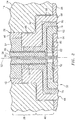
FIG. 2 is a schematic sectional illustration the tri-axial capacitance probe configured within a wall. -
FIG. 3 is a flow diagram of a method for providing a tri-axial capacitance probe. -
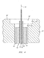
FIGS. 4-8 are a sequence of schematic sectional illustrations at different steps during the method ofFIG. 3 . -
FIG. 1 illustrates asystem 10 for rotational equipment. The rotational equipment may be configured and is described below for ease of description as a gas turbine engine. This gas turbine engine may be configured as or included in an aircraft propulsion system, an auxiliary power unit (APU), or an industrial gas turbine engine. However, the present disclosure is not limited to such exemplary gas turbine engine applications. Furthermore, thesystem 10 may alternatively be configured for a wind turbine, a water turbine or any other type of equipment (rotational or otherwise) which may include a probe as described below. - The
turbine engine system 10 ofFIG. 1 includes arotor 12, awall 14 and asensor system 16. Therotor 12 may be configured as a fan rotor, a compressor rotor, a turbine rotor or any other type of rotor included in the gas turbine engine. Therotor 12 ofFIG. 1 , for example, includes at least one rotor disk (not shown) and a plurality of rotor blades 18 (one shown), which are arranged circumferentially around the rotor disk and itsrotational axis 20 in an annular array. - The
wall 14 may be configured with a generally tubular full-hoop body. Thewall 14, for example, extends circumferentially around and axially along therotational axis 20. Thewall 14 thereby circumscribes therotor 12. Thewall 14 is also radially adjacent an outer periphery of therotor 12; e.g.,tips 22 of therotor blades 18. Thewall 14 ofFIG. 1 , for example, may be configured as a (e.g., abradable) blade outer air seal, a shroud, a turbine engine case or any other structure that forms a flow path wall within the turbine engine and around therotor 12. - The
wall 14 ofFIG. 1 includes ametal support structure 24 and aceramic coating 26; e.g., an abradable ceramic coating. Themetal support structure 24 is configured as a base of and provides structure to thewall 14. Theceramic coating 26 is disposed on a radiallyinterior surface 28 of themetal support structure 24. Theceramic coating 26 is located radially between themetal support structure 24 and therotor 12, thereby forming an outer peripheral boundary of a flow path. - The
sensor system 16 includes acontroller 30 and one or more tri-axial capacitance probes 32 (one shown). Thecontroller 30 may be implemented with a combination of hardware and software. The hardware may include a memory and at least one processing device, which may include one or more single-core and/or multi-core processors. The hardware may also or alternatively include analog and/or digital circuitry other than that described above. - The memory is configured to store software (e.g., program instructions) for execution by the processing device, which software execution may control and/or facilitate performance of one or more operations. The memory may be configured as a non-transitory computer readable medium.
- Each
tri-axial capacitance probe 32 is in signal communication (e.g., hardwired and/or wirelessly coupled) with thecontroller 30. Eachtri-axial capacitance probe 32 is configured to output data to thecontroller 30 that is indicative of a characteristic of therotor 12. For example, thetri-axial capacitance probe 32 ofFIG. 1 is configured to output data indicative of a clearance 34 (e.g., a radial distance) between therotor 12 and thewall 14. More particularly, the output data indicative of theclearance 34 between thetips 22 of therotor blades 18 and theceramic coating 26. However, in other embodiments, the output data may also or alternatively be indicative of other rotor characteristics; e.g., rotor speed, a one per revolution signal, etc. - The
tri-axial capacitance probe 32 ofFIG. 2 is mated with awall aperture 36 extending radially through thewall 14. Thiswall aperture 36 includes abore 38 and acounterbore 40, which extends partially radially into themetal support structure 24 from theinterior surface 28 to thebore 38. With this configuration, as described below in further detail, thewall 14 forms a housing for thetri-axial capacitance probe 32. This may enable thetri-axial capacitance probe 32 to take up less space for mounting since it does not require a separate housing to contain the components of theprobe 32; e.g., thewall 14 may be the only housing for theprobe 32. - The
tri-axial capacitance probe 32 ofFIG. 2 includes atri-axial conduit 42 and asensor assembly 44. Thetri-axial conduit 42 is generally arranged within thebore 38. Thesensor assembly 44 is generally within thecounterbore 40. - The
tri-axial conduit 42 includes a tubularouter conductor member 46, a tubularintermediate conductor member 48 and an inner conductor member 50 (e.g., an inner wire). Theconductor members axial centerline 52. Theintermediate conductor member 48 is disposed between, but electrically isolated from, theouter conductor member 46 and theinner conductor member 50. In particular, a tubularouter insulator member 54 is between theouter conductor member 46 and theintermediate conductor member 48. A tubularinner insulator member 56 is between theintermediate conductor member 48 and theinner conductor member 50. - The
outer conductor member 46 is directly electrically coupled with themetal support structure 24 of thewall 14. For example, there may be a tight fit between theouter conductor member 46 and themetal support structure 24. In addition or alternatively, theouter conductor member 46 may be bonded to themetal support structure 24 by conductive material; e.g., conductive adhesive material. - The
sensor assembly 44 includes an annularouter insulator 58, anannular guard 60, an annularinner insulator 62 and asensor 64. Theouter insulator 58 includes an annularinterior rim 66, anannular exterior rim 68 and an annular shelf 70 (e.g., a jog). Thisshelf 70 connects and extends radially (relative to the probe axial centerline 52) between theinterior rim 66 and theexterior rim 68. Theouter insulator 58 is nested within thewall aperture 36, where theinterior rim 66 projects into thebore 38, theexterior rim 68 is within thecounterbore 40, and theshelf 70 is abutted axially (relative to the probe axial centerline 52) against themetal support structure 24. Theinterior rim 66 is also abutted axially (relative to the probe axial centerline 52) against a distal end of theouter conductor member 46 and theouter insulator member 54. Theouter insulator 58 is bonded to thewall 14 by non-conductive material; e.g., non-conductive adhesive material. Such non-conductive material may also be between theinterior rim 66 and theconduit components - The
guard 60 includes an annularinterior rim 72, anannular exterior rim 74 and an annular shelf 76 (e.g., a jog). Thisshelf 76 connects and extends radially (relative to the probe axial centerline 52) between theinterior rim 72 and theexterior rim 74. Theannular guard 60 is nested within theouter insulator 58, whereinterior rim 72 is within theinterior rim 66, theexterior rim 74 is within theexterior rim 68, and theshelf 76 is abutted axially (relative to the probe axial centerline 52) against theshelf 70. Theguard 60 is bonded to theouter insulator 58 by non-conductive material; e.g., non-conductive adhesive material. Theinterior rim 72 is electrically coupled with theintermediate conductor member 48. For example, there may be a tight fit between theinterior rim 72 and theintermediate conductor member 48. In addition or alternatively, theinterior rim 72 may be bonded to theintermediate conductor member 48 by conductive material; e.g., conductive adhesive material. - The
inner insulator 62 includes anannular exterior rim 78 and anannular plate 80. Theexterior rim 78 is located at an outer periphery of theplate 80. Theexterior rim 78 projects axially (relative to the probe axial centerline 52) out from theplate 80. Theinner insulator 62 is nested within theguard 60, where theexterior rim 78 is within theexterior rim 74, and theplate 80 is abutted axially (relative to the probe axial centerline 52) against theshelf 76. Theinner insulator 62 is bonded to theguard 60 by non-conductive material; e.g., non-conductive adhesive material. Such non-conductive material or potting material may also be between theplate 80 and theconduit components - The
sensor 64 may be configured as an annular sensor plate. Thesensor 64 is nested within theexterior rim 78 and abutted axially (relative to the probe axial centerline 52) against theplate 80. Thesensor 64 is bonded to theinner insulator 62 by non-conductive material; e.g., non-conductive adhesive material. However, a gap may be left in theregion 82 to ensure the non-conductive material does not disrupt electrical coupling between thesensor 64 and theinner conductor member 50. Thesensor 64 is electrically coupled with theinner conductor member 50. For example, there may be a tight fit between thesensor 64 and theinner conductor member 50. In addition or alternatively, thesensor 64 may be bonded to theinner conductor member 50 by conductive material; e.g., conductive adhesive material. -
FIG. 3 is a flow diagram of amethod 300 for providing (e.g., assembling) a tri-axial capacitance probe such as theprobe 32 ofFIG. 2 . While thismethod 300 is described with reference to theprobe 32 described above with respect toFIGS. 1 and2 , themethod 300 may also be performed to assembly a probe with a different configuration. - In
step 302, thetri-axial conduit 42 is mated with anassembly fixture 84 as shown inFIG. 4 . Thetri-axial conduit 42, for example, is inserted into a fixture aperture 36' that extends axially through thefixture 84. The fixture aperture 36' includes a bore 38' and a counterbore 40', which are sized and configured the same as thebore 38 andcounterbore 40 within the wall 14 (seeFIG. 2 ). Theconduit components conduit components conduit components inner conductor member 50 projects axially away from theconduit components - In
step 304, thetri-axial conduit 42 is temporarily bonded and/or otherwise attached to thefixture 84. For example, theouter conductor member 46 is temporarily bonded to thefixture 84 with an adhesive that decomposes and/or liquefies upon being subject to an elevated temperature, which elevated temperature is below a temperature which theprobe 32 may be subjected during turbine engine operation. - In
step 306, theouter insulator 58 is nested within the aperture 36' as shown inFIG. 5 . - In
step 308, theouter insulator 58 is temporarily bonded and/or otherwise attached to thefixture 84. For example, theouter conductor member 46 is temporarily bonded to thefixture 84 with an adhesive that decomposes and/or liquefies upon being subject to an elevated temperature, which elevated temperature is below a temperature which theprobe 32 may be subjected during turbine engine operation. - In
step 310, theouter insulator 58 is (e.g., permanently) bonded and/or otherwise attached to theconduit components outer conductor member 46 is bonded to thefixture 84 with a non-conductive adhesive that maintains a bond during engine operation. - In
step 312, theguard 60 is nested within theouter insulator 58 as shown inFIG. 6 . - In
step 314, theguard 60 is (e.g., permanently) bonded and/or otherwise attached to theouter insulator 58. For example, theguard 60 is bonded to theouter insulator 58 with a non-conductive adhesive that maintains a bond during engine operation. - In
step 316, theguard 60 is (e.g., permanently) bonded and/or otherwise electrically coupled with theintermediate conductor member 48. For example, theguard 60 is bonded to theintermediate conductor member 48 with a conductive adhesive that maintains a bond during engine operation. Theguard 60 and theintermediate conductor member 48 may also or alternatively be attached via a compression type fit. - In
step 318, theinner insulator 62 is nested within theguard 60 as shown inFIG. 7 . - In
step 320, theinner insulator 62 is (e.g., permanently) bonded and/or otherwise attached to theguard 60. For example, theinner insulator 62 is bonded to theguard 60 with a non-conductive adhesive that maintains a bond during engine operation. Theinner insulator 62 may also be bonded to theinner insulator member 56 with a non-conductive adhesive. - In
step 322, thesensor 64 is nested within theinner insulator 62 as shown inFIG. 8 . - In
step 324, thesensor 64 is (e.g., permanently) bonded and/or otherwise attached to theinner insulator 62. For example, thesensor 64 is bonded to theinner insulator 62 with a non-conductive adhesive that maintains a bond during engine operation. - In
step 326, thesensor 64 is (e.g., permanently) bonded and/or otherwise electrically coupled with theinner conductor member 50. For example, thesensor 64 is bonded to theinner conductor member 50 with a conductive adhesive that maintains a bond during engine operation. Thesensor 64 and theinner conductor member 50 may also or alternatively be attached via a compression type fit. - In
step 328, theinner conductor member 50 is machined (e.g., trimmed) to be substantially flush with thesensor 64. A portion of theinner conductor member 50 which projects out from thesensor 64, for example, may be cut off and/or ground down. - In
step 330, the assembledtri-axial capacitance probe 32 is removed from thefixture 84. The adhesive between thecomponents fixture 84, for example, may be heated in order to break the adhesive bonds such that thetri-axial capacitance probe 32 may be removed from thefixture 84. - Following performance of the
method 300, thetri-axial capacitance probe 32 is disposed within thewall aperture 36 and attached to thewall 14 as described above. - In some embodiments, rather than assembling the
tri-axial capacitance probe 32 in thefixture 84, thetri-axial capacitance probe 32 may alternatively be assembled in situ with thewall 14. - In some embodiments, the
ceramic coating 26 may be applied to thewall 14 before the tri-axial capacitance probes 32 are configured with thewall 14. In other embodiments, theceramic coating 26 may be applied to thewall 14 after the tri-axial capacitance probes 32 are configured with thewall 14 where, for example, theprobes 32 are masked during the coating application. - While various embodiments of the present invention have been disclosed, it will be apparent to those of ordinary skill in the art that many more embodiments and implementations are possible within the scope of the invention. For example, the present invention as described herein includes several aspects and embodiments that include particular features. Although these features may be described individually, it is within the scope of the present invention that some or all of these features may be combined with any one of the aspects and remain within the scope of the invention. Accordingly, the present invention is not to be restricted except in light of the attached claims and their equivalents.
Claims (15)
- A method involving a wall (14) configured to circumscribe and be radially adjacent a rotor (12), the method comprising:providing a tri-axial capacitance probe (32) comprising a tri-axial conduit (42) that includes an outer conductor member (46), the tri-axial capacitance probe (32) configured to output data indicative of a characteristic of the rotor (12); andconfiguring the tri-axial capacitance probe (32) within a wall aperture (36) in the wall (14), wherein the outer conductor member (46) is electrically coupled with the wall (14), and the wall (14) is configured as a housing for the tri-axial capacitance probe (32).
- The method of claim 1, wherein the providing the tri-axial capacitance probe (32) comprises:assembling the tri-axial capacitance probe (32) in a fixture (84), wherein the fixture (84) is configured as a temporary housing for the tri-axial capacitance probe (32); andremoving the tri-axial capacitance probe (32) from the fixture (84) as a module without a housing.
- The method of claim 1 or 2, wherein the providing the tri-axial capacitance probe (32) comprises:mating the tri-axial conduit (42) with a fixture aperture (36') extending through a or the fixture (84); andtemporarily bonding the outer conductor member (46) to the fixture (80).
- The method of claim 3, wherein the providing the tri-axial capacitance probe (32) further comprises:abutting an annular outer insulator (58) against and bonding the outer insulator (58) to the outer conductor member (46) using non-conductive material; andtemporarily bonding the outer insulator (58) to the fixture (84) within a counterbore (40') of the fixture aperture (84);wherein an intermediate conductor member (48) of the tri-axial conduit (42) projects into the outer insulator (58), and an inner conductor member (50) of the tri-axial conduit (42) projects through the outer insulator (58).
- The method of claim 4, wherein the providing the tri-axial capacitance probe (32) further comprises:nesting an annular guard (60) within and bonding the guard (60) to the outer insulator (58) using non-conductive material; andelectrically coupling the guard (60) with the intermediate conductor member (48).
- The method of claim 5, wherein the providing the tri-axial capacitance probe (32) further comprises:nesting an annular inner insulator (62) within and bonding the inner insulator (62) to the guard (60) using non-conductive material;wherein the inner conductor member (50) projects through the inner insulator (62).
- The method of claim 6, wherein non-conductive material is axially between the inner insulator (62) and intermediate conductor member (48).
- The method of claim 6 or 7, wherein the providing the tri-axial capacitance probe (32) further comprises:nesting a sensor (64) within and bonding the sensor (64) to the inner insulator (62) using non-conductive material; andelectrically coupling the sensor (64) with the inner conductor member (50).
- The method of claim 8, wherein
the sensor (64) comprises an annular sensor plate, and the inner conductor member (50) projects through the sensor plate; and
the providing the tri-axial capacitance probe (32) further comprises removing a portion of the inner conductor member (50) that projects out from the sensor plate. - The method of claim 8 or 9, wherein
the providing the tri-axial capacitance probe (32) further comprises breaking the temporary bond between the outer conductor member (46) and the fixture (84) and between the outer insulator (58) and the fixture (84), and removing the tri-axial capacitance probe (32) from the fixture (84) as a module; and
the configuring the tri-axial capacitance probe (32) within the wall (14) comprises bonding the outer conductor member (46) to the wall (14) with conductive material, and bonding the outer insulator (58) to the wall (14) with non-conductive material. - An assembly (10) for rotational equipment, comprising:a rotor (12);a wall (14) circumscribing and radially adjacent the rotor (12); anda tri-axial capacitance probe (32) within an aperture (36) in the wall (14), the tri-axial capacitance probe (32) configured to output data indicative of a characteristic of the rotor (12);the tri-axial capacitance probe (32) comprising a tri-axial conduit (42) that includes a tubular outer conductor member (46) directly electrically coupled with the wall (14).
- The assembly of claim 11, wherein
the wall (14) comprises a metal support structure (24) and a ceramic coating (26) radially between the metal support structure (24) and the rotor (12); and
the outer conductor member (46) is directly electrically coupled with the metal support structure (24); and/or wherein:the rotor (12) comprises a rotor disk and a plurality of rotor blades (18) arranged circumferentially around the rotor disk (20) in an annular array; andthe tri-axial capacitance probe (32) is configured to provide data indicative of a radial clearance (34) between at least one of the rotor blades (18) and the wall (14); and/or wherein the wall (14) is configured as a housing for the tri-axial capacitance probe (32). - The method or assembly of any preceding claim, wherein
the tri-axial conduit (42) further includes an intermediate conductor member (48) and an inner conductor member (50); and
the intermediate conductor member (48) is coaxial with, between and electrically isolated from the outer conductor member (46) and the inner conductor member (50), wherein, optionally, the intermediate conductor member (48) is tubular. - The method or assembly of claim 13, wherein
the tri-axial capacitance probe (32) further comprises a sensor assembly (44) nested in a counterbore (40) in the wall (14), the sensor assembly (44) comprising a or the sensor (64) and an or the annular guard (60);
the sensor (64) is electrically coupled with the inner conductor member (50);
the guard (60) is electrically coupled with the intermediate conductor member (48); and
the guard (60) is between and electrically isolated from the wall (14) and the sensor (64). - The method or assembly of claim 14, wherein
the sensor assembly (44) further comprises an or the annular outer insulator (58) and an or the annular inner insulator (62);
the outer insulator (58) is between and bonded to the wall (14) and the guard (60); and
the inner insulator (62) is between and bonded to the guard (60) and the sensor (64).
Applications Claiming Priority (1)
| Application Number | Priority Date | Filing Date | Title |
|---|---|---|---|
| US15/269,393 US10330455B2 (en) | 2016-09-19 | 2016-09-19 | Tri-axial capacitance probe with case integrated housing |
Publications (2)
| Publication Number | Publication Date |
|---|---|
| EP3296686A1 true EP3296686A1 (en) | 2018-03-21 |
| EP3296686B1 EP3296686B1 (en) | 2019-10-30 |
Family
ID=60009416
Family Applications (1)
| Application Number | Title | Priority Date | Filing Date |
|---|---|---|---|
| EP17191548.1A Active EP3296686B1 (en) | 2016-09-19 | 2017-09-18 | Tri-axial capacitance probe with case integrated housing |
Country Status (2)
| Country | Link |
|---|---|
| US (1) | US10330455B2 (en) |
| EP (1) | EP3296686B1 (en) |
Families Citing this family (1)
| Publication number | Priority date | Publication date | Assignee | Title |
|---|---|---|---|---|
| US10738645B2 (en) | 2018-08-31 | 2020-08-11 | Raytheon Technologies Corporation | Embedded triaxial epoxy cap probe |
Citations (3)
| Publication number | Priority date | Publication date | Assignee | Title |
|---|---|---|---|---|
| FR2568004A1 (en) * | 1984-07-20 | 1986-01-24 | Onera (Off Nat Aerospatiale) | METHOD AND APPARATUS FOR PERFORMING DYNAMIC MEASUREMENT, ON A ROTATING MACHINE IN OPERATION, OF THE GAME BETWEEN THE FACES WITH REGARD TO THE ROTOR AND THE STATOR OF THIS MACHINE |
| DE3617373A1 (en) * | 1986-05-23 | 1987-11-26 | Mtu Muenchen Gmbh | CAPACITIVE MEASURING SYSTEM |
| WO1997028418A1 (en) * | 1996-02-02 | 1997-08-07 | Bicc Public Limited Company | Capacitance transducer apparatus and cables |
Family Cites Families (27)
| Publication number | Priority date | Publication date | Assignee | Title |
|---|---|---|---|---|
| US3543065A (en) | 1968-09-26 | 1970-11-24 | Shurtronics Corp | Probe for bond tester |
| US3890423A (en) | 1973-07-27 | 1975-06-17 | Nusonics | Electroacoustic transducer assembly |
| US4162111A (en) | 1977-08-25 | 1979-07-24 | E. I. Du Pont De Nemours And Company | Piezoelectric ultrasonic transducer with damped housing |
| US4455754A (en) | 1980-05-22 | 1984-06-26 | Centro Corporation | Position sensing device |
| US4544859A (en) | 1984-07-06 | 1985-10-01 | The United States Of America As Represented By The United States Department Of Energy | Non-bonded piezoelectric ultrasonic transducer |
| US5101165A (en) * | 1990-05-29 | 1992-03-31 | General Electric Company | Electrical capacitance clearanceometer |
| US5119036A (en) | 1990-05-29 | 1992-06-02 | General Electric Company | Electrical capacitance clearanceometer |
| DE19744229A1 (en) | 1997-10-07 | 1999-04-29 | Bosch Gmbh Robert | Ultrasonic transducer |
| US6268683B1 (en) | 1999-02-26 | 2001-07-31 | M&Fc Holding Company | Transducer configurations and related method |
| US6546824B2 (en) | 2001-08-16 | 2003-04-15 | Deere & Company | Sensor mounting assembly |
| US6851306B2 (en) | 2002-08-27 | 2005-02-08 | Delphi Technologies, Inc. | Method and apparatus for probe sensor assembly |
| US6774623B2 (en) | 2002-10-10 | 2004-08-10 | Delphi Technologies, Inc. | Mounting bracket for holding sensor assembly together |
| US7554324B2 (en) | 2003-10-28 | 2009-06-30 | Honeywell International Inc. | Turbine blade proximity sensor and control system |
| US6848193B1 (en) | 2003-11-26 | 2005-02-01 | General Electric Company | Methods and systems for machine monitoring system calibration |
| US7153023B2 (en) | 2004-01-12 | 2006-12-26 | General Electric Company | Methods and apparatus for installing process instrument probes |
| US7414413B2 (en) | 2005-09-20 | 2008-08-19 | General Electric Company | Blade tip clearance probe holder and a method for measuring blade tip clearance |
| US7215129B1 (en) | 2006-03-30 | 2007-05-08 | General Electric Company | Multi tip clearance measurement system and method of operation |
| GB0621620D0 (en) | 2006-10-31 | 2006-12-06 | Rolls Royce Plc | A sensor |
| GB2466404B (en) | 2007-11-21 | 2010-10-27 | Rolls Royce Plc | Turbomachine having an apparatus to measure the clearance between a rotor blade tip and a stator liner of a stator casing |
| US7876093B2 (en) | 2007-12-06 | 2011-01-25 | General Electric Company | Eddy current inspection device, proximity probe and method for assembling an eddy current inspection device |
| US20100079136A1 (en) | 2008-09-29 | 2010-04-01 | Rosemount Aerospace Inc. | Blade tip clearance measurement sensor and method for gas turbine engines |
| US8344741B2 (en) | 2008-10-16 | 2013-01-01 | General Electric Company | Systems, methods, and apparatus for monitoring clearance in a rotary machine |
| JP5099175B2 (en) | 2010-05-28 | 2012-12-12 | 株式会社村田製作所 | Ultrasonic sensor |
| JP5616700B2 (en) | 2010-06-25 | 2014-10-29 | パナソニック株式会社 | Sensor device |
| US8922203B2 (en) | 2012-01-16 | 2014-12-30 | General Electric Company | Turbomachine blade monitoring system |
| US8970228B2 (en) | 2012-05-31 | 2015-03-03 | General Electric Company | Rotational clearance measurement system and method of operation |
| US9518850B2 (en) | 2012-09-28 | 2016-12-13 | United Technologies Corporation | Embedded cap probe |
-
2016
- 2016-09-19 US US15/269,393 patent/US10330455B2/en active Active
-
2017
- 2017-09-18 EP EP17191548.1A patent/EP3296686B1/en active Active
Patent Citations (3)
| Publication number | Priority date | Publication date | Assignee | Title |
|---|---|---|---|---|
| FR2568004A1 (en) * | 1984-07-20 | 1986-01-24 | Onera (Off Nat Aerospatiale) | METHOD AND APPARATUS FOR PERFORMING DYNAMIC MEASUREMENT, ON A ROTATING MACHINE IN OPERATION, OF THE GAME BETWEEN THE FACES WITH REGARD TO THE ROTOR AND THE STATOR OF THIS MACHINE |
| DE3617373A1 (en) * | 1986-05-23 | 1987-11-26 | Mtu Muenchen Gmbh | CAPACITIVE MEASURING SYSTEM |
| WO1997028418A1 (en) * | 1996-02-02 | 1997-08-07 | Bicc Public Limited Company | Capacitance transducer apparatus and cables |
Also Published As
| Publication number | Publication date |
|---|---|
| US20180080753A1 (en) | 2018-03-22 |
| EP3296686B1 (en) | 2019-10-30 |
| US10330455B2 (en) | 2019-06-25 |
Similar Documents
| Publication | Publication Date | Title |
|---|---|---|
| RU2673361C1 (en) | Device for guiding adjustable stator blades of turbine engine and method of assembling said device | |
| JP6490149B2 (en) | Wireless aircraft engine monitoring system | |
| US9518850B2 (en) | Embedded cap probe | |
| US20160108754A1 (en) | Splitter Nose With Plasma De-Icing For Axial Turbine Engine Compressor | |
| CA2832772C (en) | Stator blades of an axial turbocompressor and manufacturing process | |
| US11333029B2 (en) | Method for manufacturing a stage of a steam turbine | |
| EP3399160A1 (en) | Method of inspecting a gas turbine engine | |
| US11175187B2 (en) | Air temperature sensor having a bushing | |
| US10033145B1 (en) | Slip ring having multiple brushes axially applied to a segmented busbar | |
| CN110672055A (en) | System and method for measuring blade clearance in a turbine engine | |
| US20170207689A1 (en) | Fan apparatus and manufacturing method of the fan apparatus | |
| EP1233148A3 (en) | Shroud assembly and method of machining the same | |
| EP3296686B1 (en) | Tri-axial capacitance probe with case integrated housing | |
| RU2585154C2 (en) | Fan or compressor of turbomachine | |
| CN104093940A (en) | Optimizing the support points of the blade struts in the method of machining the blade | |
| CN114761668A (en) | Electrical module for an aircraft turbomachine | |
| US10352326B2 (en) | Assembly for an engine which can define a blade break-off test device | |
| US20160230579A1 (en) | Rotor disk sealing and blade attachments system | |
| US12455213B2 (en) | Measurement system having a capacitance probe and an optical probe | |
| EP3323998B1 (en) | Inner shroud segment and corresponding inner shroud and gas turbine motor | |
| US10982548B2 (en) | Impeller, rotary machine, method for manufacturing impeller, and method for manufacturing rotary machine | |
| CN105822364A (en) | Centering arrangement of two parts relative to each other | |
| US11513034B2 (en) | Probe adapter for a blade outer air seal and method for using same | |
| EP4276403B1 (en) | Clearance sensor | |
| EP4717881A1 (en) | Mounting seal runner onto aircraft powerplant rotor |
Legal Events
| Date | Code | Title | Description |
|---|---|---|---|
| PUAI | Public reference made under article 153(3) epc to a published international application that has entered the european phase |
Free format text: ORIGINAL CODE: 0009012 |
|
| STAA | Information on the status of an ep patent application or granted ep patent |
Free format text: STATUS: THE APPLICATION HAS BEEN PUBLISHED |
|
| AK | Designated contracting states |
Kind code of ref document: A1 Designated state(s): AL AT BE BG CH CY CZ DE DK EE ES FI FR GB GR HR HU IE IS IT LI LT LU LV MC MK MT NL NO PL PT RO RS SE SI SK SM TR |
|
| AX | Request for extension of the european patent |
Extension state: BA ME |
|
| STAA | Information on the status of an ep patent application or granted ep patent |
Free format text: STATUS: REQUEST FOR EXAMINATION WAS MADE |
|
| STAA | Information on the status of an ep patent application or granted ep patent |
Free format text: STATUS: EXAMINATION IS IN PROGRESS |
|
| 17P | Request for examination filed |
Effective date: 20180921 |
|
| RBV | Designated contracting states (corrected) |
Designated state(s): AL AT BE BG CH CY CZ DE DK EE ES FI FR GB GR HR HU IE IS IT LI LT LU LV MC MK MT NL NO PL PT RO RS SE SI SK SM TR |
|
| 17Q | First examination report despatched |
Effective date: 20181023 |
|
| GRAP | Despatch of communication of intention to grant a patent |
Free format text: ORIGINAL CODE: EPIDOSNIGR1 |
|
| STAA | Information on the status of an ep patent application or granted ep patent |
Free format text: STATUS: GRANT OF PATENT IS INTENDED |
|
| RIC1 | Information provided on ipc code assigned before grant |
Ipc: F04D 29/52 20060101ALI20190314BHEP Ipc: G01B 7/14 20060101AFI20190314BHEP Ipc: G01M 15/14 20060101ALI20190314BHEP Ipc: F01D 21/00 20060101ALI20190314BHEP Ipc: F04D 27/00 20060101ALI20190314BHEP Ipc: F01D 25/24 20060101ALI20190314BHEP Ipc: F04D 29/32 20060101ALI20190314BHEP Ipc: F01D 5/02 20060101ALI20190314BHEP |
|
| INTG | Intention to grant announced |
Effective date: 20190403 |
|
| GRAS | Grant fee paid |
Free format text: ORIGINAL CODE: EPIDOSNIGR3 |
|
| GRAA | (expected) grant |
Free format text: ORIGINAL CODE: 0009210 |
|
| STAA | Information on the status of an ep patent application or granted ep patent |
Free format text: STATUS: THE PATENT HAS BEEN GRANTED |
|
| AK | Designated contracting states |
Kind code of ref document: B1 Designated state(s): AL AT BE BG CH CY CZ DE DK EE ES FI FR GB GR HR HU IE IS IT LI LT LU LV MC MK MT NL NO PL PT RO RS SE SI SK SM TR |
|
| REG | Reference to a national code |
Ref country code: GB Ref legal event code: FG4D |
|
| REG | Reference to a national code |
Ref country code: CH Ref legal event code: EP |
|
| REG | Reference to a national code |
Ref country code: AT Ref legal event code: REF Ref document number: 1196625 Country of ref document: AT Kind code of ref document: T Effective date: 20191115 |
|
| REG | Reference to a national code |
Ref country code: DE Ref legal event code: R096 Ref document number: 602017008183 Country of ref document: DE |
|
| REG | Reference to a national code |
Ref country code: IE Ref legal event code: FG4D |
|
| REG | Reference to a national code |
Ref country code: LT Ref legal event code: MG4D |
|
| PG25 | Lapsed in a contracting state [announced via postgrant information from national office to epo] |
Ref country code: PT Free format text: LAPSE BECAUSE OF FAILURE TO SUBMIT A TRANSLATION OF THE DESCRIPTION OR TO PAY THE FEE WITHIN THE PRESCRIBED TIME-LIMIT Effective date: 20200302 Ref country code: SE Free format text: LAPSE BECAUSE OF FAILURE TO SUBMIT A TRANSLATION OF THE DESCRIPTION OR TO PAY THE FEE WITHIN THE PRESCRIBED TIME-LIMIT Effective date: 20191030 Ref country code: LV Free format text: LAPSE BECAUSE OF FAILURE TO SUBMIT A TRANSLATION OF THE DESCRIPTION OR TO PAY THE FEE WITHIN THE PRESCRIBED TIME-LIMIT Effective date: 20191030 Ref country code: NO Free format text: LAPSE BECAUSE OF FAILURE TO SUBMIT A TRANSLATION OF THE DESCRIPTION OR TO PAY THE FEE WITHIN THE PRESCRIBED TIME-LIMIT Effective date: 20200130 Ref country code: GR Free format text: LAPSE BECAUSE OF FAILURE TO SUBMIT A TRANSLATION OF THE DESCRIPTION OR TO PAY THE FEE WITHIN THE PRESCRIBED TIME-LIMIT Effective date: 20200131 Ref country code: PL Free format text: LAPSE BECAUSE OF FAILURE TO SUBMIT A TRANSLATION OF THE DESCRIPTION OR TO PAY THE FEE WITHIN THE PRESCRIBED TIME-LIMIT Effective date: 20191030 Ref country code: LT Free format text: LAPSE BECAUSE OF FAILURE TO SUBMIT A TRANSLATION OF THE DESCRIPTION OR TO PAY THE FEE WITHIN THE PRESCRIBED TIME-LIMIT Effective date: 20191030 Ref country code: BG Free format text: LAPSE BECAUSE OF FAILURE TO SUBMIT A TRANSLATION OF THE DESCRIPTION OR TO PAY THE FEE WITHIN THE PRESCRIBED TIME-LIMIT Effective date: 20200130 Ref country code: FI Free format text: LAPSE BECAUSE OF FAILURE TO SUBMIT A TRANSLATION OF THE DESCRIPTION OR TO PAY THE FEE WITHIN THE PRESCRIBED TIME-LIMIT Effective date: 20191030 Ref country code: NL Free format text: LAPSE BECAUSE OF FAILURE TO SUBMIT A TRANSLATION OF THE DESCRIPTION OR TO PAY THE FEE WITHIN THE PRESCRIBED TIME-LIMIT Effective date: 20191030 |
|
| REG | Reference to a national code |
Ref country code: NL Ref legal event code: MP Effective date: 20191030 |
|
| PG25 | Lapsed in a contracting state [announced via postgrant information from national office to epo] |
Ref country code: IS Free format text: LAPSE BECAUSE OF FAILURE TO SUBMIT A TRANSLATION OF THE DESCRIPTION OR TO PAY THE FEE WITHIN THE PRESCRIBED TIME-LIMIT Effective date: 20200229 Ref country code: RS Free format text: LAPSE BECAUSE OF FAILURE TO SUBMIT A TRANSLATION OF THE DESCRIPTION OR TO PAY THE FEE WITHIN THE PRESCRIBED TIME-LIMIT Effective date: 20191030 Ref country code: HR Free format text: LAPSE BECAUSE OF FAILURE TO SUBMIT A TRANSLATION OF THE DESCRIPTION OR TO PAY THE FEE WITHIN THE PRESCRIBED TIME-LIMIT Effective date: 20191030 |
|
| PG25 | Lapsed in a contracting state [announced via postgrant information from national office to epo] |
Ref country code: AL Free format text: LAPSE BECAUSE OF FAILURE TO SUBMIT A TRANSLATION OF THE DESCRIPTION OR TO PAY THE FEE WITHIN THE PRESCRIBED TIME-LIMIT Effective date: 20191030 |
|
| PG25 | Lapsed in a contracting state [announced via postgrant information from national office to epo] |
Ref country code: EE Free format text: LAPSE BECAUSE OF FAILURE TO SUBMIT A TRANSLATION OF THE DESCRIPTION OR TO PAY THE FEE WITHIN THE PRESCRIBED TIME-LIMIT Effective date: 20191030 Ref country code: DK Free format text: LAPSE BECAUSE OF FAILURE TO SUBMIT A TRANSLATION OF THE DESCRIPTION OR TO PAY THE FEE WITHIN THE PRESCRIBED TIME-LIMIT Effective date: 20191030 Ref country code: RO Free format text: LAPSE BECAUSE OF FAILURE TO SUBMIT A TRANSLATION OF THE DESCRIPTION OR TO PAY THE FEE WITHIN THE PRESCRIBED TIME-LIMIT Effective date: 20191030 Ref country code: CZ Free format text: LAPSE BECAUSE OF FAILURE TO SUBMIT A TRANSLATION OF THE DESCRIPTION OR TO PAY THE FEE WITHIN THE PRESCRIBED TIME-LIMIT Effective date: 20191030 Ref country code: ES Free format text: LAPSE BECAUSE OF FAILURE TO SUBMIT A TRANSLATION OF THE DESCRIPTION OR TO PAY THE FEE WITHIN THE PRESCRIBED TIME-LIMIT Effective date: 20191030 |
|
| REG | Reference to a national code |
Ref country code: DE Ref legal event code: R097 Ref document number: 602017008183 Country of ref document: DE |
|
| REG | Reference to a national code |
Ref country code: AT Ref legal event code: MK05 Ref document number: 1196625 Country of ref document: AT Kind code of ref document: T Effective date: 20191030 |
|
| PG25 | Lapsed in a contracting state [announced via postgrant information from national office to epo] |
Ref country code: SM Free format text: LAPSE BECAUSE OF FAILURE TO SUBMIT A TRANSLATION OF THE DESCRIPTION OR TO PAY THE FEE WITHIN THE PRESCRIBED TIME-LIMIT Effective date: 20191030 Ref country code: SK Free format text: LAPSE BECAUSE OF FAILURE TO SUBMIT A TRANSLATION OF THE DESCRIPTION OR TO PAY THE FEE WITHIN THE PRESCRIBED TIME-LIMIT Effective date: 20191030 Ref country code: IT Free format text: LAPSE BECAUSE OF FAILURE TO SUBMIT A TRANSLATION OF THE DESCRIPTION OR TO PAY THE FEE WITHIN THE PRESCRIBED TIME-LIMIT Effective date: 20191030 |
|
| PLBE | No opposition filed within time limit |
Free format text: ORIGINAL CODE: 0009261 |
|
| STAA | Information on the status of an ep patent application or granted ep patent |
Free format text: STATUS: NO OPPOSITION FILED WITHIN TIME LIMIT |
|
| 26N | No opposition filed |
Effective date: 20200731 |
|
| PG25 | Lapsed in a contracting state [announced via postgrant information from national office to epo] |
Ref country code: SI Free format text: LAPSE BECAUSE OF FAILURE TO SUBMIT A TRANSLATION OF THE DESCRIPTION OR TO PAY THE FEE WITHIN THE PRESCRIBED TIME-LIMIT Effective date: 20191030 Ref country code: AT Free format text: LAPSE BECAUSE OF FAILURE TO SUBMIT A TRANSLATION OF THE DESCRIPTION OR TO PAY THE FEE WITHIN THE PRESCRIBED TIME-LIMIT Effective date: 20191030 |
|
| REG | Reference to a national code |
Ref country code: CH Ref legal event code: PL |
|
| REG | Reference to a national code |
Ref country code: BE Ref legal event code: MM Effective date: 20200930 |
|
| PG25 | Lapsed in a contracting state [announced via postgrant information from national office to epo] |
Ref country code: LU Free format text: LAPSE BECAUSE OF NON-PAYMENT OF DUE FEES Effective date: 20200918 |
|
| PG25 | Lapsed in a contracting state [announced via postgrant information from national office to epo] |
Ref country code: IE Free format text: LAPSE BECAUSE OF NON-PAYMENT OF DUE FEES Effective date: 20200918 Ref country code: LI Free format text: LAPSE BECAUSE OF NON-PAYMENT OF DUE FEES Effective date: 20200930 Ref country code: CH Free format text: LAPSE BECAUSE OF NON-PAYMENT OF DUE FEES Effective date: 20200930 Ref country code: BE Free format text: LAPSE BECAUSE OF NON-PAYMENT OF DUE FEES Effective date: 20200930 |
|
| PG25 | Lapsed in a contracting state [announced via postgrant information from national office to epo] |
Ref country code: TR Free format text: LAPSE BECAUSE OF FAILURE TO SUBMIT A TRANSLATION OF THE DESCRIPTION OR TO PAY THE FEE WITHIN THE PRESCRIBED TIME-LIMIT Effective date: 20191030 Ref country code: MT Free format text: LAPSE BECAUSE OF FAILURE TO SUBMIT A TRANSLATION OF THE DESCRIPTION OR TO PAY THE FEE WITHIN THE PRESCRIBED TIME-LIMIT Effective date: 20191030 Ref country code: CY Free format text: LAPSE BECAUSE OF FAILURE TO SUBMIT A TRANSLATION OF THE DESCRIPTION OR TO PAY THE FEE WITHIN THE PRESCRIBED TIME-LIMIT Effective date: 20191030 |
|
| PG25 | Lapsed in a contracting state [announced via postgrant information from national office to epo] |
Ref country code: MK Free format text: LAPSE BECAUSE OF FAILURE TO SUBMIT A TRANSLATION OF THE DESCRIPTION OR TO PAY THE FEE WITHIN THE PRESCRIBED TIME-LIMIT Effective date: 20191030 Ref country code: MC Free format text: LAPSE BECAUSE OF FAILURE TO SUBMIT A TRANSLATION OF THE DESCRIPTION OR TO PAY THE FEE WITHIN THE PRESCRIBED TIME-LIMIT Effective date: 20191030 |
|
| REG | Reference to a national code |
Ref country code: DE Ref legal event code: R081 Ref document number: 602017008183 Country of ref document: DE Owner name: RAYTHEON TECHNOLOGIES CORPORATION (N.D.GES.D.S, US Free format text: FORMER OWNER: UNITED TECHNOLOGIES CORPORATION, FARMINGTON, CONN., US Ref country code: DE Ref legal event code: R081 Ref document number: 602017008183 Country of ref document: DE Owner name: RTX CORPORATION (N.D.GES.D. STAATES DELAWARE),, US Free format text: FORMER OWNER: UNITED TECHNOLOGIES CORPORATION, FARMINGTON, CONN., US |
|
| P01 | Opt-out of the competence of the unified patent court (upc) registered |
Effective date: 20230520 |
|
| PGFP | Annual fee paid to national office [announced via postgrant information from national office to epo] |
Ref country code: DE Payment date: 20250820 Year of fee payment: 9 |
|
| PGFP | Annual fee paid to national office [announced via postgrant information from national office to epo] |
Ref country code: GB Payment date: 20250827 Year of fee payment: 9 |
|
| PGFP | Annual fee paid to national office [announced via postgrant information from national office to epo] |
Ref country code: FR Payment date: 20250820 Year of fee payment: 9 |
|
| REG | Reference to a national code |
Ref country code: DE Ref legal event code: R081 Ref document number: 602017008183 Country of ref document: DE Owner name: RTX CORPORATION (N.D.GES.D. STAATES DELAWARE),, US Free format text: FORMER OWNER: RAYTHEON TECHNOLOGIES CORPORATION (N.D.GES.D.STAATES DELAWARE), ARLINGTON, VA, US |