EP3296556A1 - Biogas-fired engine - Google Patents
Biogas-fired engine Download PDFInfo
- Publication number
- EP3296556A1 EP3296556A1 EP16792794.6A EP16792794A EP3296556A1 EP 3296556 A1 EP3296556 A1 EP 3296556A1 EP 16792794 A EP16792794 A EP 16792794A EP 3296556 A1 EP3296556 A1 EP 3296556A1
- Authority
- EP
- European Patent Office
- Prior art keywords
- biogas
- engine
- pressure
- venturi mixer
- air
- Prior art date
- Legal status (The legal status is an assumption and is not a legal conclusion. Google has not performed a legal analysis and makes no representation as to the accuracy of the status listed.)
- Withdrawn
Links
Images



Classifications
-
- F—MECHANICAL ENGINEERING; LIGHTING; HEATING; WEAPONS; BLASTING
- F02—COMBUSTION ENGINES; HOT-GAS OR COMBUSTION-PRODUCT ENGINE PLANTS
- F02M—SUPPLYING COMBUSTION ENGINES IN GENERAL WITH COMBUSTIBLE MIXTURES OR CONSTITUENTS THEREOF
- F02M21/00—Apparatus for supplying engines with non-liquid fuels, e.g. gaseous fuels stored in liquid form
- F02M21/02—Apparatus for supplying engines with non-liquid fuels, e.g. gaseous fuels stored in liquid form for gaseous fuels
- F02M21/04—Gas-air mixing apparatus
-
- F—MECHANICAL ENGINEERING; LIGHTING; HEATING; WEAPONS; BLASTING
- F02—COMBUSTION ENGINES; HOT-GAS OR COMBUSTION-PRODUCT ENGINE PLANTS
- F02D—CONTROLLING COMBUSTION ENGINES
- F02D19/00—Controlling engines characterised by their use of non-liquid fuels, pluralities of fuels, or non-fuel substances added to the combustible mixtures
- F02D19/02—Controlling engines characterised by their use of non-liquid fuels, pluralities of fuels, or non-fuel substances added to the combustible mixtures peculiar to engines working with gaseous fuels
- F02D19/021—Control of components of the fuel supply system
- F02D19/023—Control of components of the fuel supply system to adjust the fuel mass or volume flow
-
- F—MECHANICAL ENGINEERING; LIGHTING; HEATING; WEAPONS; BLASTING
- F02—COMBUSTION ENGINES; HOT-GAS OR COMBUSTION-PRODUCT ENGINE PLANTS
- F02D—CONTROLLING COMBUSTION ENGINES
- F02D41/00—Electrical control of supply of combustible mixture or its constituents
- F02D41/0025—Controlling engines characterised by use of non-liquid fuels, pluralities of fuels, or non-fuel substances added to the combustible mixtures
- F02D41/0027—Controlling engines characterised by use of non-liquid fuels, pluralities of fuels, or non-fuel substances added to the combustible mixtures the fuel being gaseous
-
- F—MECHANICAL ENGINEERING; LIGHTING; HEATING; WEAPONS; BLASTING
- F02—COMBUSTION ENGINES; HOT-GAS OR COMBUSTION-PRODUCT ENGINE PLANTS
- F02D—CONTROLLING COMBUSTION ENGINES
- F02D41/00—Electrical control of supply of combustible mixture or its constituents
- F02D41/02—Circuit arrangements for generating control signals
- F02D41/04—Introducing corrections for particular operating conditions
- F02D41/042—Introducing corrections for particular operating conditions for stopping the engine
-
- F—MECHANICAL ENGINEERING; LIGHTING; HEATING; WEAPONS; BLASTING
- F02—COMBUSTION ENGINES; HOT-GAS OR COMBUSTION-PRODUCT ENGINE PLANTS
- F02D—CONTROLLING COMBUSTION ENGINES
- F02D41/00—Electrical control of supply of combustible mixture or its constituents
- F02D41/02—Circuit arrangements for generating control signals
- F02D41/04—Introducing corrections for particular operating conditions
- F02D41/06—Introducing corrections for particular operating conditions for engine starting or warming up
- F02D41/062—Introducing corrections for particular operating conditions for engine starting or warming up for starting
-
- F—MECHANICAL ENGINEERING; LIGHTING; HEATING; WEAPONS; BLASTING
- F02—COMBUSTION ENGINES; HOT-GAS OR COMBUSTION-PRODUCT ENGINE PLANTS
- F02D—CONTROLLING COMBUSTION ENGINES
- F02D41/00—Electrical control of supply of combustible mixture or its constituents
- F02D41/02—Circuit arrangements for generating control signals
- F02D41/04—Introducing corrections for particular operating conditions
- F02D41/06—Introducing corrections for particular operating conditions for engine starting or warming up
- F02D41/062—Introducing corrections for particular operating conditions for engine starting or warming up for starting
- F02D41/064—Introducing corrections for particular operating conditions for engine starting or warming up for starting at cold start
-
- F—MECHANICAL ENGINEERING; LIGHTING; HEATING; WEAPONS; BLASTING
- F02—COMBUSTION ENGINES; HOT-GAS OR COMBUSTION-PRODUCT ENGINE PLANTS
- F02M—SUPPLYING COMBUSTION ENGINES IN GENERAL WITH COMBUSTIBLE MIXTURES OR CONSTITUENTS THEREOF
- F02M21/00—Apparatus for supplying engines with non-liquid fuels, e.g. gaseous fuels stored in liquid form
- F02M21/02—Apparatus for supplying engines with non-liquid fuels, e.g. gaseous fuels stored in liquid form for gaseous fuels
- F02M21/0203—Apparatus for supplying engines with non-liquid fuels, e.g. gaseous fuels stored in liquid form for gaseous fuels characterised by the type of gaseous fuel
- F02M21/0215—Mixtures of gaseous fuels; Natural gas; Biogas; Mine gas; Landfill gas
-
- F—MECHANICAL ENGINEERING; LIGHTING; HEATING; WEAPONS; BLASTING
- F02—COMBUSTION ENGINES; HOT-GAS OR COMBUSTION-PRODUCT ENGINE PLANTS
- F02D—CONTROLLING COMBUSTION ENGINES
- F02D19/00—Controlling engines characterised by their use of non-liquid fuels, pluralities of fuels, or non-fuel substances added to the combustible mixtures
- F02D19/06—Controlling engines characterised by their use of non-liquid fuels, pluralities of fuels, or non-fuel substances added to the combustible mixtures peculiar to engines working with pluralities of fuels, e.g. alternatively with light and heavy fuel oil, other than engines indifferent to the fuel consumed
- F02D19/08—Controlling engines characterised by their use of non-liquid fuels, pluralities of fuels, or non-fuel substances added to the combustible mixtures peculiar to engines working with pluralities of fuels, e.g. alternatively with light and heavy fuel oil, other than engines indifferent to the fuel consumed simultaneously using pluralities of fuels
- F02D19/10—Controlling engines characterised by their use of non-liquid fuels, pluralities of fuels, or non-fuel substances added to the combustible mixtures peculiar to engines working with pluralities of fuels, e.g. alternatively with light and heavy fuel oil, other than engines indifferent to the fuel consumed simultaneously using pluralities of fuels peculiar to compression-ignition engines in which the main fuel is gaseous
-
- F—MECHANICAL ENGINEERING; LIGHTING; HEATING; WEAPONS; BLASTING
- F02—COMBUSTION ENGINES; HOT-GAS OR COMBUSTION-PRODUCT ENGINE PLANTS
- F02D—CONTROLLING COMBUSTION ENGINES
- F02D2200/00—Input parameters for engine control
- F02D2200/02—Input parameters for engine control the parameters being related to the engine
- F02D2200/021—Engine temperature
-
- F—MECHANICAL ENGINEERING; LIGHTING; HEATING; WEAPONS; BLASTING
- F02—COMBUSTION ENGINES; HOT-GAS OR COMBUSTION-PRODUCT ENGINE PLANTS
- F02D—CONTROLLING COMBUSTION ENGINES
- F02D2200/00—Input parameters for engine control
- F02D2200/02—Input parameters for engine control the parameters being related to the engine
- F02D2200/06—Fuel or fuel supply system parameters
- F02D2200/0602—Fuel pressure
-
- F—MECHANICAL ENGINEERING; LIGHTING; HEATING; WEAPONS; BLASTING
- F02—COMBUSTION ENGINES; HOT-GAS OR COMBUSTION-PRODUCT ENGINE PLANTS
- F02M—SUPPLYING COMBUSTION ENGINES IN GENERAL WITH COMBUSTIBLE MIXTURES OR CONSTITUENTS THEREOF
- F02M21/00—Apparatus for supplying engines with non-liquid fuels, e.g. gaseous fuels stored in liquid form
- F02M21/02—Apparatus for supplying engines with non-liquid fuels, e.g. gaseous fuels stored in liquid form for gaseous fuels
- F02M21/04—Gas-air mixing apparatus
- F02M21/047—Venturi mixer
-
- Y—GENERAL TAGGING OF NEW TECHNOLOGICAL DEVELOPMENTS; GENERAL TAGGING OF CROSS-SECTIONAL TECHNOLOGIES SPANNING OVER SEVERAL SECTIONS OF THE IPC; TECHNICAL SUBJECTS COVERED BY FORMER USPC CROSS-REFERENCE ART COLLECTIONS [XRACs] AND DIGESTS
- Y02—TECHNOLOGIES OR APPLICATIONS FOR MITIGATION OR ADAPTATION AGAINST CLIMATE CHANGE
- Y02T—CLIMATE CHANGE MITIGATION TECHNOLOGIES RELATED TO TRANSPORTATION
- Y02T10/00—Road transport of goods or passengers
- Y02T10/10—Internal combustion engine [ICE] based vehicles
- Y02T10/30—Use of alternative fuels, e.g. biofuels
Definitions
- the present invention relates to a biogas-fired engine that uses a biogas.
- a biogas-fired engine that solely uses a biogas as a single fuel involves such an inconvenience that a negative suction pressure of a venturi mixer is insufficient although the venturi mixer needs to suck a predetermined amount of biogas in a case of performing stoichiometric combustion.
- a conceivable approach is to pressurize, with a fan, a pre-compression chamber of a pressure equalizing valve which is arranged upstream of a venturi mixer, to raise a gas pressure at a location downstream of the pressure equalizing valve, thereby pushing a biogas in.
- This requires that the fan be kept driven during an operation of the engine, which causes such an inconvenience that the operation efficiency of the biogas-fired engine is lowered to a degree corresponding to self-consumption power.
- Another conceivable approach is to provide a gas compressor between a pressure equalizing valve and a venturi mixer so that a biogas is directly pressurized to be pushed in. This, however, has a risk that compression of the biogas, which contains a large amount of moisture, may cause condensed water to be produced so that a malfunction of an intake valve or a throttle valve occurs.
- the present invention is made in view of the circumstances described above, and an object of the present invention is to provide a biogas-fired engine capable of sucking a biogas at a flow rate necessary for stoichiometric combustion by raising a negative suction pressure of a venturi mixer.
- a biogas-fired engine is a biogas-fired engine fueled solely by a biogas derived from organic waste, the biogas-fired engine including: fuel pressure adjustment means arranged in a fuel path; air-fuel ratio adjustment means arranged in the fuel path at a location downstream of the fuel pressure adjustment means; and a venturi mixer arranged at a location where the fuel path joins an intake path, wherein the fuel pressure adjustment means adjusts a pressure to approximately atmospheric pressure, and an area of the venturi mixer is adjusted so as to provide an air flow velocity that allows the biogas to be sucked at a flow rate necessary for causing predetermined combustion with a predetermined engine output by a differential pressure between a pressure of the venturi mixer and a pressure adjusted by the fuel pressure adjustment means.
- a maximum passage area of the air-fuel ratio adjustment means and a variable range of the passage area may be adjusted in accordance with the adjustment of the area of the venturi mixer.
- the biogas-fired engine described above may further include: heating means provided in an engine cooling water circuit; and control means for, upon receiving a start command, driving a cooling water pump and sensing a cooling water temperature, and if the temperature is lower than a predetermined temperature, driving the heating means until the temperature reaches the predetermined temperature or higher while standing by for driving engine forced-drive means.
- the biogas-fired engine described above may further include: a gasifier for combusting organic waste to produce a biogas, the gasifier being provided in the fuel path at a location upstream of the fuel pressure adjustment means; heating means provided in an engine cooling water circuit; and control means for starting combustion in the gasifier a first predetermined time before an engine start time, sensing a cooling water temperature, and if the temperature is lower than a predetermined temperature, driving a cooling water pump a second predetermined time before, the second predetermined time being shorter than the first predetermined time, while driving the heating means until the temperature reaches the predetermined temperature or higher.
- the area of the venturi mixer where air passes through may be adjusted such that an air flow velocity is obtained, the air flow velocity enabling the biogas and air to be mixed in such a manner as to provide a calorific value that is comparable to a calorific value of a mixed gas obtained in a case where stoichiometric combustion of the engine is performed with a predetermined output by using a town gas.
- the adjustment may be made so as to obtain an air flow velocity that enables the biogas and air to be mixed at a biogas/air ratio of 54/46 to 40/60.
- the biogas can be supplied to a combustion chamber of the engine at a flow rate necessary for causing predetermined combustion with a predetermined engine output by a differential pressure caused as a result of adjustment of the area of the venturi mixer, without any need to separately provide pressurization means.
- a second aspect of the present invention can address the problem that the need to narrow the maximum passage area of the air-fuel ratio adjustment means arises as a negative suction pressure of the venturi mixer increases. It can also address the problem that the need to limit the variable range of the passage area arises because a variation in the biogas sucking flow rate caused by a change in the passage area increases along with an increase in the negative suction pressure.
- a combustible boundary of air-fuel ratios is narrowed, and therefore it is difficult to start the engine at a low temperature, but in a third aspect of the present invention, a combustible range of air-fuel ratios can be widened by heating a cooling water to warm up the engine, thus enabling the engine to be started at a low temperature.
- preparations necessary for starting the biogas-fired engine can be made economically.
- the biogas for operating the engine, can be supplied to a combustion chamber of the engine at a flow rate necessary for causing predetermined combustion with a predetermined engine output by a differential pressure caused as a result of adjustment of the area of the venturi mixer, without any need to separately provide pressurization means.
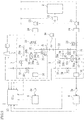
- FIG. 1 shows a configuration of an engine 4 of a biogas-fired engine 1
- FIG. 2 schematically shows an entire configuration of the biogas-fired engine 1
- FIG. 3 shows the relationship between an air flow velocity of a venturi mixer 40 and an output of the engine 4 in the biogas-fired engine 1.
- the biogas-fired engine 1 is configured such that: a biogas produced in a gasifier 2 is supplied from a pressure equalizing valve unit 3 to the engine 4 via an A/F valve 41 and a venturi mixer 40; and the passage area of the venturi mixer 40 is adjusted so as to provide a target air flow velocity Tas at which a predetermined flow rate of biogas can be sucked by using a differential pressure between the pressure equalizing valve unit 3 and the venturi mixer 40.
- the gasifier 2 which is formed of a furnace that thermally decomposes biomass raw materials such as wood chippings or rice hulls, is configured to produce, as a biogas, a pyrolysis gas as exemplified by a hydrocarbon gas obtained as a result of thermal decomposition under a low oxygen condition.
- the type of the gasifier 2 is not particularly limited, as long as it is able to produce a pyrolysis gas as a biogas by thermally decomposing biomass raw materials.
- a calorific value of the biogas varies over time because of heterogeneity of the raw materials and a variation in heating in the gasifier 2.
- the embodiment of the present invention illustrates example cases of 1000 kcal/Nm 3 and 1300 kcal/Nm 3 .
- the biogas having passed through the scrubber 21 is sent downstream by a blower 23, and sent to one portion or branched into a plurality of portions (two portions in this embodiment) in accordance with the number of connected engines 4, where the number of connected engines 4 differs depending on the amount of produced biogas.
- the biogas cooled by the scrubber 21 contains much moisture. Therefore, a drain pot 24 is arranged downstream of the blower 23.
- the drain pot 24 is configured to collect condensed water contained in the biogas.
- the biogas with the condensed water removed therefrom is supplied to the engine 4 via the pressure equalizing valve unit 3.
- the gasifier 2, the scrubber 21, the blower 23, and the like, are controlled by a control unit 10.
- the biogas After passing through the drain pot 24, the biogas is supplied to the pressure equalizing valve unit 3.
- the pressure equalizing valve unit 3 is configured to supply the biogas from the gasifier 2 to the engine 4 via the pressure equalizing valve 30 which is arranged in a gas supply path 31.
- a gas shut-off valve 33 is arranged on the upstream end side of the gas supply path 31, so that a supply of the biogas to the gas supply path 31 can be shut off.
- a drain pot 34 is arranged on the downstream end side of the gas supply path 31, so that condensed water contained in the biogas to be supplied to the engine 4 can be collected again.
- the pressure equalizing valve 30 is arranged in the gas supply path 31 at a location between the gas shut-off valve 33 and the drain pot 34.
- the pressure equalizing valve 30 has a pressure adjustment valve 30d provided in an atmospheric pressure release path 30c extending from an actuator 30b on a diaphragm 30a.
- the pressure equalizing valve 30 opens the pressure adjustment valve 30d to release the atmospheric pressure release path 30c to atmospheric pressure, thereby allowing the biogas supplied from a portion of the gas supply path 31 upstream of the pressure equalizing valve 30 to be supplied under atmospheric pressure to a portion of the gas supply path 31 downstream of the pressure equalizing valve 30 irrespective of a supply pressure in the upstream portion of the gas supply path 31.
- a pressure sensor 16 is arranged for measuring a primary gas pressure of the biogas to be supplied to the pressure equalizing valve 30.
- a pressure sensor 17 is arranged for measuring a secondary gas pressure of the biogas supplied from the pressure equalizing valve 30. Information given from these pressure sensors 16, 17 is sent to the control unit 10.
- An air supply path 32 is connected to the gas supply path 31 at a location between the gas shut-off valve 33 and the pressure equalizing valve 30. Communication between the air supply path 32 and the gas supply path 31 is normally shut off by an air purge valve 35 which is arranged on the air supply path 32 side. Upon requirement of air purge, the air purge valve 35 is opened so that the pressure equalizing valve 30 is purged with air from the air supply path 32 via the gas supply path 31. This is why an air purge blower 36 is arranged on the upstream end side of the air supply path 32.
- a discharge path 37 for discharging a surplus biogas to a flare stack 5 is arranged in the gas supply path 31 at a location between the pressure equalizing valve 30 and the drain pot 34.
- the surplus biogas is subjected to a combustion process in the flare stack 5.
- An air purge release valve 38 is arranged in the discharge path 37. The air purge release valve 38 is opened when the pressure equalizing valve 30 is purged with air, and thereby allows air after the air purge to escape from the gas supply path 31 through the discharge path 37.
- An exit 3a which corresponds to a downstream end portion of the gas supply path 31 of the pressure equalizing valve unit 3 is connected to the A/F valve 41 of the engine 4.
- the pressure equalizing valve unit 3 is controlled by the control unit 10.
- the venturi mixer 40 configured to mix air with the biogas supplied from the A/F valve 41 is provided in an intake path 43 which is connected to a cylinder head 42.
- a throttle valve 44 is arranged between the venturi mixer 40 and the cylinder head 42.
- a silencer 46 is arranged in an exhaust path 45 which is connected to the cylinder head 42, and a three-way catalyst 47 is arranged between the silencer 46 and the cylinder head 42.
- the engine 4 is provided with a pick-up sensor 11 for detecting a rotation angle of a crankshaft 48 and a pick-up sensor 12 for detecting a rotation angle of a cam shaft 49.
- a pre oxygen sensor 13 and a different post oxygen sensor 14 are arranged on the sides of the three-way catalyst 47 where an exhaust gas enters and exits, respectively.
- an entire region sensor 15 is arranged on the side of the three-way catalyst 47 where the exhaust gas exits.
- the control unit 10 renders a cell (not shown) conducting, thereby enabling the pick-up sensor 11 for detecting a rotation angle of the crankshaft 48 to detect whether or not the engine 4 is started.
- the control unit 10 senses the compression top dead center based on a combination of signals of the pick-up sensor 11 and the pick-up sensor 12, and performs an ignition control with ignition means.
- the control unit 10 also controls the amount of biogas to be produced by the gasifier 2, and has a control map such that the control unit 10 performs a perturbation control on the stoichiometric operation of the engine 4 in accordance with information of the control map, the control map including the relationship of the degree of opening of the A/F valve 41 with detection results given from the pre oxygen sensor 13, the post oxygen sensor 14, and the entire region sensor 15 in a case of performing the perturbation control on the engine 4 in the stoichiometric operation by using the biogas.
- the used venturi mixer 40 is the one in which the passage area is set so as to provide a target air flow velocity Tas at which the biogas and air can be mixed at a mixing ratio necessary for causing stoichiometric combustion in the engine 4 with a predetermined output P.
- FIG. 3 shows the relationship between the output of the engine 4 and the air flow velocity of the venturi mixer 40 necessary for achieving a mixing ratio between the fuel gas and air for operating the engine 4 with stoichiometric combustion in the biogas-fired engine 1 according to the present invention.
- the venturi mixer 40 needs to have an air flow velocity of a if a town gas 13A is used; the same venturi mixer 40 needs to have an air flow velocity of b if a biogas G2 obtained when its combustible component has a calorific value of 1300 kcal/Nm 3 is supplied while being pushed into the same venturi mixer 40 from the pressure equalizing valve unit 3 side toward the venturi mixer 40 side via the A/F valve 41; and the same venturi mixer 40 needs to have an air flow velocity of c if a biogas G1 obtained when its combustible component has a calorific value of 1000 kcal/Nm 3 is supplied while being pushed into the same venturi mixer 40 from the pressure equalizing valve unit 3 side toward the venturi mixer 40 side via the A/F valve 41.
- the biogases G1 and G2 are distinguished by their calorific values, but both of them are a biogas produced by
- the venturi mixer 40 needs to have a negative suction pressure for sucking a greater amount of biogas G1, and therefore the venturi mixer 40 is changed to the one in which the passage area is set smaller so as to provide the target air flow velocity Tas that is higher than the air flow velocity c necessary in a case of pushing the biogas G1 in.
- a calorific value of the combustible component contained in the mixed gas necessary for operating the engine 4 in stoichiometric combustion with the predetermined output P is determined by the mixing ratio between the town gas 13A and air in case of operating the engine 4 in stoichiometric combustion and a calorific value of the combustible component contained in the town gas 13A which is already obvious.
- a mixing ratio between the biogas G1 and air necessary for operating the engine 4 in stoichiometric combustion with the predetermined output P can be identified based on a contrast between the found calorific value and the calorific value of the town gas 13A, as shown in FIG. 4(b) .
- the venturi mixer 40 is used in which the passage area is set such that the air flow velocity increases by the increment S1 in order to provide the negative suction pressure, and thereby the engine 4 can be operated in stoichiometric combustion with the predetermined output P by using the biogas G1.
- a mixing ratio between the biogas G2 and air necessary for operating the engine 4 in stoichiometric combustion with the predetermined output P can be identified from the calorific value, as shown in FIG. 4(c) .
- the venturi mixer 40 is used in which the passage area is set such that the air flow velocity increases by an increment S2 to obtain the target air flow velocity Tas which is also coincident with the air flow velocity a necessary when the town gas 13A is used in order to provide the negative suction pressure, and thereby the engine 4 can be operated in stoichiometric combustion with the predetermined output P by using the biogas G2.
- the venturi mixer 40 in which the passage area is set so as to increase the air flow velocity by the increment S1 to S2 that enables achievement of a biogas/air mixing ratio of 1/1 and more specifically 54/46 to 40/60 in accordance with the calorific value of the combustible component of the biogas relative to the mixing ratio of 1:17 between the town gas 13A and air is selectively used, so that the engine 4 can be operated in stoichiometric combustion with the predetermined output P, though not necessarily because the calorific value of the biogas varies over time at this time.
- the biogas-fired engine 1 having the above-described configuration, which adopts the venturi mixer 40 whose passage area is set so as to increase the air flow velocity by the increment S1 to S2, enables an amount of biogas necessary for stoichiometric combustion to be supplied to the engine 4 without the need to push a biogas into the venturi mixer 40 from the pressure equalizing valve unit 3 side even when a combustible component in the obtained biogas has a low calorific value.
- a venturi mixer 40 configured such that a biogas is pushed into the venturi mixer 40 from the pressure equalizing valve unit 3 side, as shown in FIG. 5 , a rapid shift to the lean state occurs at a time of starting the engine 4, which makes a start of the engine 4 difficult.
- Adoption of the venturi mixer 40 in which the passage area is set so as to increase the air flow velocity by the increment S1 to S2 as in the biogas-fired engine 1 of the present invention enables a sufficient amount of biogas to be supplied even at a time of starting the engine 4. Thus, a start of the engine 4 may not be made difficult.
- the venturi mixer 40 is used in which the passage area is set smaller so as to increase the air flow velocity by the increment S1 (or S2) to provide an air flow velocity higher the air flow velocity c (or b) required in a case of pushing the biogas in, thereby enabling a large amount of biogas to be supplied to the engine 4. Therefore, a slight change in the degree of opening of the A/F valve 41 leads to a large change in the amount of biogas supply.
- the venturi mixer 40 is used in which the passage area is set smaller so as to increase the air flow velocity by the increment S1 (or S2) to provide an air flow velocity higher the air flow velocity c (or b) required in a case of pushing the biogas in, thereby enabling a large amount of biogas to be supplied to the engine 4. Therefore, a slight change in the degree of opening of the A/F valve 41 leads to a large change in the amount of biogas supply.
- an opening degree adjustment range of the A/F valve 41 is changed to an opening degree adjustment range W2 corresponding to the air flow velocity increment S1 (or S2) which is lower than an opening degree adjustment range W1 of the venturi mixer 40 used in a case of the air flow velocity c (or b), and an adjustment width of the opening degree adjustment range W2 is also reduced.
- the A/F valve 41 is able to adjust the amount of biogas supply accordingly.
- the biogas-fired engine 1 of the present invention includes a heater 52 provided in a cooling water circuit 51 of the engine 4, so that cooling water heated by the heater 52 is circulated by a cooling water pump 53.
- the heater 52 and the cooling water pump 53 are controlled by the control unit 10.
- the control unit 10 drives the cooling water pump 53 and senses the cooling water temperature, and if it is lower than the predetermined temperature D, continues the heating by the heater 52 and stands by for driving the cell of the engine 4.
- the control unit 10 firstly starts to operate the gasifier 2, and in conjunction therewith, starts the engine 4.
- the start is difficult even though the operation of the gasifier 2 is started, if a biogas sufficient for operating the engine 4 is not immediately produced or if the engine 4 is not heated to a temperature equal to or higher than the predetermined temperature D.
- the control unit 10, therefore, is configured to wait for elapse of a time T1 and a time T2, the time T1 being a time required for the amount of produced biogas to reach a suppliable amount, the time T2 being a time required for the engine 4 to be heated to a temperature equal to or higher than the predetermined temperature D.
- control unit 10 is configured to drive the cooling water pump 53 and sense the cooling water temperature, and if it is lower than the predetermined temperature D, continue the heating by the heater 52 until reaching a temperature equal to or higher than the predetermined temperature D. Only after the engine 4 is heated to a temperature equal to or higher than the predetermined temperature D, the engine 4 is started by the cell of the engine 4.
- control unit 10 is configured to wait for elapse of the time T1 which is required for reaching a calorific value that makes the biogas suppliable, and also wait for elapse of the time T2 which is required for the engine 4 to be heated to a temperature equal to or higher than the predetermined temperature D, before starting the engine 4. This can ensure that the engine 4 be started even at a low temperature because preparations necessary for starting the biogas-fired engine 1 are completed over time.
- control unit 10 continues the operation of the gasifier 2 unless the biogas-fired engine 1 is stopped, because once the gasifier 2 is stopped, a time is required for the amount of produced biogas to reach a suppliable amount.
- the engine 4 on the other hand, is stopped or started in accordance with conditions that are set in the control unit 10, and thus repeats a start and a stop many times a day.
- the control unit 10 stops both the gasifier 2 and the engine 4 in its stop program. At this time, the engine 4 is stopped immediately, whereas the gasifier 2 takes a time T3 for gradual settlement of biogas production after the stop. A surplus biogas produced after the engine 4 is stopped is subjected to a combustion process in the flare stack 5.
- control unit 10 is configured to, after starting operation, wait for elapse of the time T1 until the amount of produced biogas reaches a suppliable amount, but instead it may be configured to wait for reaching a predetermined pressure. In such a configuration, a suppliable amount of produced biogas can be detected by waiting for the primary gas pressure sensed by the pressure sensor 16 upstream of the pressure equalizing valve 30 to become equal to or higher than a predetermined value.
- the control unit 10 is configured to start the engine 4 after waiting for elapse of the time T1 required for reaching a calorific value that makes the biogas suppliable and elapse of the time T2 required for the engine 4 to be heated to a temperature equal to or higher than the predetermined temperature D, but a configuration is also acceptable in which the control unit 10 starts to heat the engine 4 up to a temperature equal to or higher than the predetermined temperature D simultaneously with starting the operation of the gasifier 2. In this configuration, the start of the engine 4 can be started after elapse of the time T1 or the time T2, whichever is longer.
Landscapes
- Engineering & Computer Science (AREA)
- Chemical & Material Sciences (AREA)
- Combustion & Propulsion (AREA)
- Mechanical Engineering (AREA)
- General Engineering & Computer Science (AREA)
- Chemical Kinetics & Catalysis (AREA)
- General Chemical & Material Sciences (AREA)
- Oil, Petroleum & Natural Gas (AREA)
- Output Control And Ontrol Of Special Type Engine (AREA)
- Electrical Control Of Air Or Fuel Supplied To Internal-Combustion Engine (AREA)
Abstract
Description
- The present invention relates to a biogas-fired engine that uses a biogas.
- As a method for operating an engine that is fueled by a biogas derived from organic waste, a dual fuel engine that uses a biogas as a fuel and a diesel oil as an auxiliary fuel is conventionally known (for example, see Patent Literature 1 (PTL 1)).
- In a dual fuel engine of this type, which uses a diesel oil as an auxiliary fuel, the operation is performed irrespective of the magnitude of a negative suction pressure in sucking a biogas in a mixer.
- PTL 1: Japanese Patent No.
4070115 - As compared to the conventional dual fuel engine mentioned above, a biogas-fired engine that solely uses a biogas as a single fuel involves such an inconvenience that a negative suction pressure of a venturi mixer is insufficient although the venturi mixer needs to suck a predetermined amount of biogas in a case of performing stoichiometric combustion.
- A conceivable approach is to pressurize, with a fan, a pre-compression chamber of a pressure equalizing valve which is arranged upstream of a venturi mixer, to raise a gas pressure at a location downstream of the pressure equalizing valve, thereby pushing a biogas in. This, however, requires that the fan be kept driven during an operation of the engine, which causes such an inconvenience that the operation efficiency of the biogas-fired engine is lowered to a degree corresponding to self-consumption power.
- Another conceivable approach is to provide a gas compressor between a pressure equalizing valve and a venturi mixer so that a biogas is directly pressurized to be pushed in. This, however, has a risk that compression of the biogas, which contains a large amount of moisture, may cause condensed water to be produced so that a malfunction of an intake valve or a throttle valve occurs.
- The present invention is made in view of the circumstances described above, and an object of the present invention is to provide a biogas-fired engine capable of sucking a biogas at a flow rate necessary for stoichiometric combustion by raising a negative suction pressure of a venturi mixer.
- To solve the problems described above, a biogas-fired engine according to an aspect of the present invention is a biogas-fired engine fueled solely by a biogas derived from organic waste, the biogas-fired engine including: fuel pressure adjustment means arranged in a fuel path; air-fuel ratio adjustment means arranged in the fuel path at a location downstream of the fuel pressure adjustment means; and a venturi mixer arranged at a location where the fuel path joins an intake path, wherein the fuel pressure adjustment means adjusts a pressure to approximately atmospheric pressure, and an area of the venturi mixer is adjusted so as to provide an air flow velocity that allows the biogas to be sucked at a flow rate necessary for causing predetermined combustion with a predetermined engine output by a differential pressure between a pressure of the venturi mixer and a pressure adjusted by the fuel pressure adjustment means.
- In the biogas-fired engine described above, a maximum passage area of the air-fuel ratio adjustment means and a variable range of the passage area may be adjusted in accordance with the adjustment of the area of the venturi mixer.
- The biogas-fired engine described above may further include: heating means provided in an engine cooling water circuit; and control means for, upon receiving a start command, driving a cooling water pump and sensing a cooling water temperature, and if the temperature is lower than a predetermined temperature, driving the heating means until the temperature reaches the predetermined temperature or higher while standing by for driving engine forced-drive means.
- The biogas-fired engine described above may further include: a gasifier for combusting organic waste to produce a biogas, the gasifier being provided in the fuel path at a location upstream of the fuel pressure adjustment means; heating means provided in an engine cooling water circuit; and control means for starting combustion in the gasifier a first predetermined time before an engine start time, sensing a cooling water temperature, and if the temperature is lower than a predetermined temperature, driving a cooling water pump a second predetermined time before, the second predetermined time being shorter than the first predetermined time, while driving the heating means until the temperature reaches the predetermined temperature or higher.
- In biogas-fired engine described above, the area of the venturi mixer where air passes through may be adjusted such that an air flow velocity is obtained, the air flow velocity enabling the biogas and air to be mixed in such a manner as to provide a calorific value that is comparable to a calorific value of a mixed gas obtained in a case where stoichiometric combustion of the engine is performed with a predetermined output by using a town gas.
- In the biogas-fired engine described above, the adjustment may be made so as to obtain an air flow velocity that enables the biogas and air to be mixed at a biogas/air ratio of 54/46 to 40/60.
- As described above, in a first aspect of the present invention, for operating the engine, the biogas can be supplied to a combustion chamber of the engine at a flow rate necessary for causing predetermined combustion with a predetermined engine output by a differential pressure caused as a result of adjustment of the area of the venturi mixer, without any need to separately provide pressurization means.
- A second aspect of the present invention can address the problem that the need to narrow the maximum passage area of the air-fuel ratio adjustment means arises as a negative suction pressure of the venturi mixer increases. It can also address the problem that the need to limit the variable range of the passage area arises because a variation in the biogas sucking flow rate caused by a change in the passage area increases along with an increase in the negative suction pressure.
- When the mixed gas temperature is a low temperature, a combustible boundary of air-fuel ratios is narrowed, and therefore it is difficult to start the engine at a low temperature, but in a third aspect of the present invention, a combustible range of air-fuel ratios can be widened by heating a cooling water to warm up the engine, thus enabling the engine to be started at a low temperature.
- In a fourth aspect of the present invention, preparations necessary for starting the biogas-fired engine can be made economically.
- In fifth and sixth aspects of the present invention, for operating the engine, the biogas can be supplied to a combustion chamber of the engine at a flow rate necessary for causing predetermined combustion with a predetermined engine output by a differential pressure caused as a result of adjustment of the area of the venturi mixer, without any need to separately provide pressurization means.
-
- [
FIG. 1 ] A schematic diagram showing a configuration of an engine of a biogas-fired engine according to the present invention. - [
FIG. 2 ] A schematic diagram showing an entire configuration of the biogas-fired engine according to the present invention. - [
FIG. 3 ] A graph showing the relationship between an engine output and the air flow velocity of a venturi mixer in the biogas-fired engine according to the present invention. - [
FIG. 4 ] Pie charts each showing a mixing ratio between a fuel gas and air in a case where the engine of the biogas-fired engine according to the present invention performs a stoichiometric operation with a predetermined output, of which: (a) shows a mixing ratio between a town gas and air; (b) shows a mixing ratio between a biogas and air in a case of the biogas having a calorific value of 1000 kcal/Nm3; and (c) shows a mixing ratio between a biogas and air in a case of the biogas having a calorific value of 1300 kcal/Nm3. - [
FIG. 5 ] A graph showing the relationship between an excess air ratio and a flow rate of a mixed gas having passed through a venturi mixer when the venturi mixer according to the present invention is adopted as contrasted to when another venturi mixer is adopted in an engine of a biogas-fired engine. - [
FIG. 6 ] A graph showing the relationship between the area of a passage in which air passes through in the venturi mixer of the biogas-fired engine according to the present invention and the effective opening area of an A/F valve located upstream of the venturi mixer. - [
FIG. 7 ] Graphs showing the relationship of a mixed gas intake temperature with an excess air ratio and the relationship of an engine temperature with a starting rotation frequency in the biogas-fired engine according to the present invention. - [
FIG. 8 ] A diagram for explanation of controls performed in the biogas-fired engine according to the present invention, which diagram contains graphs showing time-dependent changes in a gasifier operation control, an engine operation control, and a cooling-water heating control. - In the following, an embodiment of the present invention will be described with reference to the drawings.
-
FIG. 1 shows a configuration of anengine 4 of a biogas-firedengine 1;FIG. 2 schematically shows an entire configuration of the biogas-firedengine 1; andFIG. 3 shows the relationship between an air flow velocity of aventuri mixer 40 and an output of theengine 4 in the biogas-firedengine 1. - The biogas-fired
engine 1 according to the present invention is configured such that: a biogas produced in agasifier 2 is supplied from a pressure equalizingvalve unit 3 to theengine 4 via an A/F valve 41 and aventuri mixer 40; and the passage area of theventuri mixer 40 is adjusted so as to provide a target air flow velocity Tas at which a predetermined flow rate of biogas can be sucked by using a differential pressure between the pressure equalizingvalve unit 3 and theventuri mixer 40. - The
gasifier 2, which is formed of a furnace that thermally decomposes biomass raw materials such as wood chippings or rice hulls, is configured to produce, as a biogas, a pyrolysis gas as exemplified by a hydrocarbon gas obtained as a result of thermal decomposition under a low oxygen condition. The type of thegasifier 2 is not particularly limited, as long as it is able to produce a pyrolysis gas as a biogas by thermally decomposing biomass raw materials. Various types are adoptable including an updraft fixed bed type, a downdraft fixed bed type, a bubbling fluidized bed type, a circulating fluidized bed type, an entrained flow type, an internally fired rotary kiln, an externally fired rotary kiln, and the like. A calorific value of the biogas varies over time because of heterogeneity of the raw materials and a variation in heating in thegasifier 2. The embodiment of the present invention illustrates example cases of 1000 kcal/Nm3 and 1300 kcal/Nm3. - The biogas produced by the
gasifier 2, which is obtained as a result of thermal decomposition, has a high temperature as it is. This is why ascrubber 21 configured to disperse water in a space is arranged downstream of thegasifier 2. As the biogas passes through thescrubber 21, the biogas is cooled. - The biogas having passed through the
scrubber 21 is sent downstream by ablower 23, and sent to one portion or branched into a plurality of portions (two portions in this embodiment) in accordance with the number of connectedengines 4, where the number of connectedengines 4 differs depending on the amount of produced biogas. At this time, the biogas cooled by thescrubber 21 contains much moisture. Therefore, adrain pot 24 is arranged downstream of theblower 23. Thedrain pot 24 is configured to collect condensed water contained in the biogas. The biogas with the condensed water removed therefrom is supplied to theengine 4 via the pressure equalizingvalve unit 3. Thegasifier 2, thescrubber 21, theblower 23, and the like, are controlled by acontrol unit 10. - After passing through the
drain pot 24, the biogas is supplied to the pressure equalizingvalve unit 3. - The pressure equalizing
valve unit 3 is configured to supply the biogas from thegasifier 2 to theengine 4 via thepressure equalizing valve 30 which is arranged in agas supply path 31. - A gas shut-off
valve 33 is arranged on the upstream end side of thegas supply path 31, so that a supply of the biogas to thegas supply path 31 can be shut off. Adrain pot 34 is arranged on the downstream end side of thegas supply path 31, so that condensed water contained in the biogas to be supplied to theengine 4 can be collected again. - The
pressure equalizing valve 30 is arranged in thegas supply path 31 at a location between the gas shut-offvalve 33 and thedrain pot 34. Thepressure equalizing valve 30 has apressure adjustment valve 30d provided in an atmosphericpressure release path 30c extending from anactuator 30b on adiaphragm 30a. Thepressure equalizing valve 30 opens thepressure adjustment valve 30d to release the atmosphericpressure release path 30c to atmospheric pressure, thereby allowing the biogas supplied from a portion of thegas supply path 31 upstream of thepressure equalizing valve 30 to be supplied under atmospheric pressure to a portion of thegas supply path 31 downstream of thepressure equalizing valve 30 irrespective of a supply pressure in the upstream portion of thegas supply path 31. In the portion of thegas supply path 31 upstream of thepressure equalizing valve 30, apressure sensor 16 is arranged for measuring a primary gas pressure of the biogas to be supplied to thepressure equalizing valve 30. In the portion of thegas supply path 31 downstream of thepressure equalizing valve 30, apressure sensor 17 is arranged for measuring a secondary gas pressure of the biogas supplied from thepressure equalizing valve 30. Information given from thesepressure sensors control unit 10. - An
air supply path 32 is connected to thegas supply path 31 at a location between the gas shut-offvalve 33 and thepressure equalizing valve 30. Communication between theair supply path 32 and thegas supply path 31 is normally shut off by anair purge valve 35 which is arranged on theair supply path 32 side. Upon requirement of air purge, theair purge valve 35 is opened so that thepressure equalizing valve 30 is purged with air from theair supply path 32 via thegas supply path 31. This is why anair purge blower 36 is arranged on the upstream end side of theair supply path 32. - A
discharge path 37 for discharging a surplus biogas to aflare stack 5 is arranged in thegas supply path 31 at a location between thepressure equalizing valve 30 and thedrain pot 34. The surplus biogas is subjected to a combustion process in theflare stack 5. An airpurge release valve 38 is arranged in thedischarge path 37. The airpurge release valve 38 is opened when thepressure equalizing valve 30 is purged with air, and thereby allows air after the air purge to escape from thegas supply path 31 through thedischarge path 37. - An
exit 3a which corresponds to a downstream end portion of thegas supply path 31 of the pressure equalizingvalve unit 3 is connected to the A/F valve 41 of theengine 4. Thus, the biogas having passed through thedrain pot 34 of the pressure equalizingvalve unit 3 can be supplied to the A/F valve 41 of theengine 4. The pressure equalizingvalve unit 3 is controlled by thecontrol unit 10. - In the
engine 4, theventuri mixer 40 configured to mix air with the biogas supplied from the A/F valve 41 is provided in anintake path 43 which is connected to acylinder head 42. Athrottle valve 44 is arranged between theventuri mixer 40 and thecylinder head 42. Asilencer 46 is arranged in anexhaust path 45 which is connected to thecylinder head 42, and a three-way catalyst 47 is arranged between thesilencer 46 and thecylinder head 42. - The
engine 4 is provided with a pick-upsensor 11 for detecting a rotation angle of acrankshaft 48 and a pick-upsensor 12 for detecting a rotation angle of acam shaft 49. Apre oxygen sensor 13 and a differentpost oxygen sensor 14 are arranged on the sides of the three-way catalyst 47 where an exhaust gas enters and exits, respectively. In addition, anentire region sensor 15 is arranged on the side of the three-way catalyst 47 where the exhaust gas exits. - At a time of starting the biogas-fired
engine 1, thecontrol unit 10 renders a cell (not shown) conducting, thereby enabling the pick-upsensor 11 for detecting a rotation angle of thecrankshaft 48 to detect whether or not theengine 4 is started. In addition, thecontrol unit 10 senses the compression top dead center based on a combination of signals of the pick-upsensor 11 and the pick-upsensor 12, and performs an ignition control with ignition means. - The
control unit 10 also controls the amount of biogas to be produced by thegasifier 2, and has a control map such that thecontrol unit 10 performs a perturbation control on the stoichiometric operation of theengine 4 in accordance with information of the control map, the control map including the relationship of the degree of opening of the A/F valve 41 with detection results given from thepre oxygen sensor 13, thepost oxygen sensor 14, and theentire region sensor 15 in a case of performing the perturbation control on theengine 4 in the stoichiometric operation by using the biogas. - The used
venturi mixer 40 is the one in which the passage area is set so as to provide a target air flow velocity Tas at which the biogas and air can be mixed at a mixing ratio necessary for causing stoichiometric combustion in theengine 4 with a predetermined output P. For example,FIG. 3 shows the relationship between the output of theengine 4 and the air flow velocity of theventuri mixer 40 necessary for achieving a mixing ratio between the fuel gas and air for operating theengine 4 with stoichiometric combustion in the biogas-firedengine 1 according to the present invention. To obtain the predetermined output P of theengine 4 of the biogas-firedengine 1, theventuri mixer 40 needs to have an air flow velocity of a if atown gas 13A is used; thesame venturi mixer 40 needs to have an air flow velocity of b if a biogas G2 obtained when its combustible component has a calorific value of 1300 kcal/Nm3 is supplied while being pushed into thesame venturi mixer 40 from the pressure equalizingvalve unit 3 side toward theventuri mixer 40 side via the A/F valve 41; and thesame venturi mixer 40 needs to have an air flow velocity of c if a biogas G1 obtained when its combustible component has a calorific value of 1000 kcal/Nm3 is supplied while being pushed into thesame venturi mixer 40 from the pressure equalizingvalve unit 3 side toward theventuri mixer 40 side via the A/F valve 41. For convenience of illustration, the biogases G1 and G2 are distinguished by their calorific values, but both of them are a biogas produced by thegasifier 2 with its calorific value varying over time. - Here, to obtain the predetermined output P of the
engine 4 only with a negative suction pressure of theventuri mixer 40 without push-in of the biogas G1 in a case of using the biogas G1 which is obtained when its combustible component has a calorific value of 1000 kcal/Nm3, theventuri mixer 40 needs to have a negative suction pressure for sucking a greater amount of biogas G1, and therefore theventuri mixer 40 is changed to the one in which the passage area is set smaller so as to provide the target air flow velocity Tas that is higher than the air flow velocity c necessary in a case of pushing the biogas G1 in. - In
FIG. 3 , the target air flow velocity Tas necessary for obtaining the predetermined output P of theengine 4 only with a negative suction pressure of theventuri mixer 40 without push-in of the biogas G1 in a case of using the biogas G1 which is obtained when its combustible component has a calorific value of 1000 kcal/Nm3 is coincident with the air flow velocity a which is necessary if thetown gas 13A is used, and an increment of the air flow velocity is S1. - That is, as shown in
FIG. 4(a) , a calorific value of the combustible component contained in the mixed gas necessary for operating theengine 4 in stoichiometric combustion with the predetermined output P is determined by the mixing ratio between thetown gas 13A and air in case of operating theengine 4 in stoichiometric combustion and a calorific value of the combustible component contained in thetown gas 13A which is already obvious. Thus, if a sampling of the biogas G1 is taken from thegasifier 2 and a calorific value of the combustible component is found, a mixing ratio between the biogas G1 and air necessary for operating theengine 4 in stoichiometric combustion with the predetermined output P can be identified based on a contrast between the found calorific value and the calorific value of thetown gas 13A, as shown inFIG. 4(b) . To obtain a negative suction pressure that achieves such a mixing ratio between the biogas G1 and air, theventuri mixer 40 is used in which the passage area is set such that the air flow velocity increases by the increment S1 in order to provide the negative suction pressure, and thereby theengine 4 can be operated in stoichiometric combustion with the predetermined output P by using the biogas G1. - In a case of using the biogas G2 which is obtained when its combustible component has a calorific value of 1300 kcal/Nm3 as well, a mixing ratio between the biogas G2 and air necessary for operating the
engine 4 in stoichiometric combustion with the predetermined output P can be identified from the calorific value, as shown inFIG. 4(c) . To obtain a negative suction pressure that achieves such a mixing ratio between the biogas G2 and air, theventuri mixer 40 is used in which the passage area is set such that the air flow velocity increases by an increment S2 to obtain the target air flow velocity Tas which is also coincident with the air flow velocity a necessary when thetown gas 13A is used in order to provide the negative suction pressure, and thereby theengine 4 can be operated in stoichiometric combustion with the predetermined output P by using the biogas G2. - As shown in
FIG. 4(b) and FIG. 4(c) , as for the biogas G1 to G2 obtained when the combustible component has a calorific value of 1000 kcal/Nm3 to 1300 kcal/Nm3, theventuri mixer 40 in which the passage area is set so as to increase the air flow velocity by the increment S1 to S2 that enables achievement of a biogas/air mixing ratio of 1/1 and more specifically 54/46 to 40/60 in accordance with the calorific value of the combustible component of the biogas relative to the mixing ratio of 1:17 between thetown gas 13A and air is selectively used, so that theengine 4 can be operated in stoichiometric combustion with the predetermined output P, though not necessarily because the calorific value of the biogas varies over time at this time. - The biogas-fired
engine 1 having the above-described configuration, which adopts theventuri mixer 40 whose passage area is set so as to increase the air flow velocity by the increment S1 to S2, enables an amount of biogas necessary for stoichiometric combustion to be supplied to theengine 4 without the need to push a biogas into theventuri mixer 40 from the pressure equalizingvalve unit 3 side even when a combustible component in the obtained biogas has a low calorific value. This eliminates the risk that a malfunction of the A/F valve 41, theventuri mixer 40, or thethrottle valve 44 might be caused by condensed water generated by push-in of the biogas, and it is possible to operate theengine 4 of the biogas-firedengine 1 with the predetermined output P. - In a
venturi mixer 40 configured such that a biogas is pushed into theventuri mixer 40 from the pressure equalizingvalve unit 3 side, as shown inFIG. 5 , a rapid shift to the lean state occurs at a time of starting theengine 4, which makes a start of theengine 4 difficult. Adoption of theventuri mixer 40 in which the passage area is set so as to increase the air flow velocity by the increment S1 to S2 as in the biogas-firedengine 1 of the present invention enables a sufficient amount of biogas to be supplied even at a time of starting theengine 4. Thus, a start of theengine 4 may not be made difficult. - Since the A/
F valve 41 is arranged between the pressure equalizingvalve unit 3 and theventuri mixer 40, the amount of biogas supplied from theventuri mixer 40 to theengine 4 is influenced by the degree of opening of the A/F valve 41. In addition, as described above, theventuri mixer 40 is used in which the passage area is set smaller so as to increase the air flow velocity by the increment S1 (or S2) to provide an air flow velocity higher the air flow velocity c (or b) required in a case of pushing the biogas in, thereby enabling a large amount of biogas to be supplied to theengine 4. Therefore, a slight change in the degree of opening of the A/F valve 41 leads to a large change in the amount of biogas supply. Thus, as shown inFIG. 6 , in accordance with the passage area of theventuri mixer 40 being set smaller, an opening degree adjustment range of the A/F valve 41 is changed to an opening degree adjustment range W2 corresponding to the air flow velocity increment S1 (or S2) which is lower than an opening degree adjustment range W1 of theventuri mixer 40 used in a case of the air flow velocity c (or b), and an adjustment width of the opening degree adjustment range W2 is also reduced. - As a result, even when the negative suction pressure in the
venturi mixer 40 increases by an increment corresponding to the air flow velocity increment S1 (or S2), the A/F valve 41 is able to adjust the amount of biogas supply accordingly. - As shown in
FIG. 7 , unless theengine 4 has a temperature equal to or higher than a predetermined temperature D, a combustion boundary has a narrow width and the starting rotation frequency is low, which makes a start difficult. In this respect, the biogas-firedengine 1 of the present invention includes aheater 52 provided in acooling water circuit 51 of theengine 4, so that cooling water heated by theheater 52 is circulated by a coolingwater pump 53. Theheater 52 and the coolingwater pump 53 are controlled by thecontrol unit 10. At this time, upon receiving an instruction to start the biogas-firedengine 1, thecontrol unit 10 drives the coolingwater pump 53 and senses the cooling water temperature, and if it is lower than the predetermined temperature D, continues the heating by theheater 52 and stands by for driving the cell of theengine 4. This configuration, in which theengine 4 is started after heated to a temperature equal to or higher than the predetermined temperature D, provides a wider combustible range of air-fuel ratios, and enables theengine 4 to start at a low temperature. - To start the biogas-fired
engine 1 having the above-described configuration, as shown inFIG. 8 , thecontrol unit 10 firstly starts to operate thegasifier 2, and in conjunction therewith, starts theengine 4. Here, the start is difficult even though the operation of thegasifier 2 is started, if a biogas sufficient for operating theengine 4 is not immediately produced or if theengine 4 is not heated to a temperature equal to or higher than the predetermined temperature D. Thecontrol unit 10, therefore, is configured to wait for elapse of a time T1 and a time T2, the time T1 being a time required for the amount of produced biogas to reach a suppliable amount, the time T2 being a time required for theengine 4 to be heated to a temperature equal to or higher than the predetermined temperature D. That is, thecontrol unit 10 is configured to drive the coolingwater pump 53 and sense the cooling water temperature, and if it is lower than the predetermined temperature D, continue the heating by theheater 52 until reaching a temperature equal to or higher than the predetermined temperature D. Only after theengine 4 is heated to a temperature equal to or higher than the predetermined temperature D, theengine 4 is started by the cell of theengine 4. - As thus far described, the
control unit 10 is configured to wait for elapse of the time T1 which is required for reaching a calorific value that makes the biogas suppliable, and also wait for elapse of the time T2 which is required for theengine 4 to be heated to a temperature equal to or higher than the predetermined temperature D, before starting theengine 4. This can ensure that theengine 4 be started even at a low temperature because preparations necessary for starting the biogas-firedengine 1 are completed over time. - Then, the
control unit 10 continues the operation of thegasifier 2 unless the biogas-firedengine 1 is stopped, because once thegasifier 2 is stopped, a time is required for the amount of produced biogas to reach a suppliable amount. Theengine 4, on the other hand, is stopped or started in accordance with conditions that are set in thecontrol unit 10, and thus repeats a start and a stop many times a day. - After stopping the biogas-fired
engine 1, thecontrol unit 10 stops both thegasifier 2 and theengine 4 in its stop program. At this time, theengine 4 is stopped immediately, whereas thegasifier 2 takes a time T3 for gradual settlement of biogas production after the stop. A surplus biogas produced after theengine 4 is stopped is subjected to a combustion process in theflare stack 5. - In the biogas-fired engine described above 1, the
control unit 10 is configured to, after starting operation, wait for elapse of the time T1 until the amount of produced biogas reaches a suppliable amount, but instead it may be configured to wait for reaching a predetermined pressure. In such a configuration, a suppliable amount of produced biogas can be detected by waiting for the primary gas pressure sensed by thepressure sensor 16 upstream of thepressure equalizing valve 30 to become equal to or higher than a predetermined value. - The
control unit 10 is configured to start theengine 4 after waiting for elapse of the time T1 required for reaching a calorific value that makes the biogas suppliable and elapse of the time T2 required for theengine 4 to be heated to a temperature equal to or higher than the predetermined temperature D, but a configuration is also acceptable in which thecontrol unit 10 starts to heat theengine 4 up to a temperature equal to or higher than the predetermined temperature D simultaneously with starting the operation of thegasifier 2. In this configuration, the start of theengine 4 can be started after elapse of the time T1 or the time T2, whichever is longer. - It should be noted that the present invention may be embodied in many different forms without departing from the spirit or essential characteristics thereof. The above-described embodiments are therefore to be considered in all respects only as illustrative and not restrictive. The scope of the present invention is defined by the claims, and never bound by the description. All modifications and changes which come within the scope of the claims are to be embraced by the present invention.
-
- 1
- biogas-fired engine
- 10
- control unit
- 2
- gasifier
- 30
- pressure equalizing valve (fuel pressure adjustment means)
- 31
- gas supply path (fuel path)
- 4
- engine
- 40
- venturi mixer
- 41
- A/F valve (air-fuel ratio adjustment means)
- 43
- intake path
- 51
- cooling water circuit
- 52
- heater (heating means)
- 53
- cooling water pump
- D
- predetermined temperature
- G1
- biogas
- G2
- biogas
- S1
- air flow velocity increment
- S2
- air flow velocity increment
- Tas
- target air flow velocity (air flow velocity)
- T1
- time (first predetermined time)
- T2
- time (second predetermined time)
- P
- output
Claims (6)
- A biogas-fired engine fueled solely by a biogas derived from organic waste, the biogas-fired engine comprising:fuel pressure adjustment means arranged in a fuel path;air-fuel ratio adjustment means arranged in the fuel path at a location downstream of the fuel pressure adjustment means; anda venturi mixer arranged at a location where the fuel path joins an intake path, whereinthe fuel pressure adjustment means adjusts a pressure to approximately atmospheric pressure, and an area of the venturi mixer is adjusted so as to provide an air flow velocity that allows the biogas to be sucked at a flow rate necessary for causing predetermined combustion with a predetermined engine output by a differential pressure between a pressure of the venturi mixer and a pressure adjusted by the fuel pressure adjustment means.
- The biogas-fired engine according to claim 1, wherein
a maximum passage area of the air-fuel ratio adjustment means and a variable range of the passage area are adjusted in accordance with the adjustment of the area of the venturi mixer. - The biogas-fired engine according to claim 1, further comprising
heating means provided in an engine cooling water circuit, and
control means for, upon receiving a start command, driving a cooling water pump and sensing a cooling water temperature, and if the temperature is lower than a predetermined temperature, driving the heating means until the temperature reaches the predetermined temperature or higher while standing by for driving engine forced-drive means. - The biogas-fired engine according to claim 1, further comprising:a gasifier for combusting organic waste to produce a biogas, the gasifier being provided in the fuel path at a location upstream of the fuel pressure adjustment means,heating means provided in an engine cooling water circuit, andcontrol means for starting combustion in the gasifier a first predetermined time before an engine start time, sensing a cooling water temperature, and if the temperature is lower than a predetermined temperature, driving a cooling water pump a second predetermined time before, the second predetermined time being shorter than the first predetermined time, while driving the heating means until the temperature reaches the predetermined temperature or higher.
- The biogas-fired engine according to claim 1, wherein
the area of the venturi mixer where air passes through is adjusted such that an air flow velocity is obtained, the air flow velocity enabling the biogas and air to be mixed in such a manner as to provide a calorific value that is comparable to a calorific value of a mixed gas obtained in a case where stoichiometric combustion of the engine is performed with a predetermined output by using a town gas. - The biogas-fired engine according to claim 5, wherein
the adjustment is made so as to obtain an air flow velocity that enables the biogas and air to be mixed at a biogas/air ratio of 54/46 to 40/60.
Applications Claiming Priority (2)
| Application Number | Priority Date | Filing Date | Title |
|---|---|---|---|
| JP2015098828A JP6576682B2 (en) | 2015-05-14 | 2015-05-14 | Biogas combustion engine |
| PCT/JP2016/064340 WO2016182070A1 (en) | 2015-05-14 | 2016-05-13 | Biogas-fired engine |
Publications (2)
| Publication Number | Publication Date |
|---|---|
| EP3296556A1 true EP3296556A1 (en) | 2018-03-21 |
| EP3296556A4 EP3296556A4 (en) | 2018-08-08 |
Family
ID=57248927
Family Applications (1)
| Application Number | Title | Priority Date | Filing Date |
|---|---|---|---|
| EP16792794.6A Withdrawn EP3296556A4 (en) | 2015-05-14 | 2016-05-13 | Biogas-fired engine |
Country Status (3)
| Country | Link |
|---|---|
| EP (1) | EP3296556A4 (en) |
| JP (1) | JP6576682B2 (en) |
| WO (1) | WO2016182070A1 (en) |
Cited By (1)
| Publication number | Priority date | Publication date | Assignee | Title |
|---|---|---|---|---|
| WO2019219484A1 (en) * | 2018-05-16 | 2019-11-21 | Meri Environmental Solutions Gmbh | Method and apparatus for drying a preferably traveling material web by means of at least one drying device heated by means of biogas and comprising infrared radiators |
Families Citing this family (3)
| Publication number | Priority date | Publication date | Assignee | Title |
|---|---|---|---|---|
| CN111577472B (en) * | 2020-05-28 | 2022-04-19 | 广西玉柴机器股份有限公司 | Fuel control method and system of gas engine |
| CN112879171A (en) * | 2021-04-14 | 2021-06-01 | 广东西电动力科技股份有限公司 | Multi-machine parallel operation system of methane unit |
| JP2023170920A (en) * | 2022-05-20 | 2023-12-01 | ダイハツ工業株式会社 | biogas engine system |
Family Cites Families (14)
| Publication number | Priority date | Publication date | Assignee | Title |
|---|---|---|---|---|
| FR981461A (en) * | 1943-04-14 | 1951-05-28 | Volcan Sa | Installation for the gas supply of internal combustion engines |
| US3464803A (en) * | 1966-03-30 | 1969-09-02 | Ambac Ind | Variable venturi carburetor |
| US4694802A (en) * | 1984-09-21 | 1987-09-22 | Lowi Jr Alvin | Compression ignition engine fumigation system |
| JPH07253049A (en) * | 1994-03-14 | 1995-10-03 | Yamaha Motor Co Ltd | Fuel supply device for gas fuel engine |
| JPH07253051A (en) * | 1994-03-14 | 1995-10-03 | Yamaha Motor Co Ltd | Fuel vaporizer for gas fuel engine |
| JP2002038992A (en) * | 2000-07-26 | 2002-02-06 | Toyota Motor Corp | Internal combustion engine |
| DE10306145A1 (en) * | 2003-02-14 | 2004-08-26 | Robert Bosch Gmbh | Direct start method for an internal combustion engine (ICE) injects fuel directly into the ICE's combustion chambers filled with air |
| JP2005030302A (en) * | 2003-07-14 | 2005-02-03 | Tokyo Gas Co Ltd | Gas engine, and method for controlling the same |
| JP2008267349A (en) * | 2007-04-24 | 2008-11-06 | Yanmar Co Ltd | Engine |
| US9181901B2 (en) * | 2009-11-03 | 2015-11-10 | Indian Institute Of Science | Producer gas carburettor |
| JP2012017663A (en) * | 2010-07-06 | 2012-01-26 | Yanmar Co Ltd | Gas engine starting control method |
| JP5667413B2 (en) * | 2010-10-22 | 2015-02-12 | ヤンマー株式会社 | Engine control method |
| JP6128975B2 (en) * | 2013-06-11 | 2017-05-17 | ヤンマー株式会社 | Gas engine |
| EP2952713B1 (en) * | 2014-06-03 | 2016-09-14 | Yanmar Co., Ltd. | Biomass gas-fired engine |
-
2015
- 2015-05-14 JP JP2015098828A patent/JP6576682B2/en not_active Expired - Fee Related
-
2016
- 2016-05-13 EP EP16792794.6A patent/EP3296556A4/en not_active Withdrawn
- 2016-05-13 WO PCT/JP2016/064340 patent/WO2016182070A1/en not_active Ceased
Cited By (2)
| Publication number | Priority date | Publication date | Assignee | Title |
|---|---|---|---|---|
| WO2019219484A1 (en) * | 2018-05-16 | 2019-11-21 | Meri Environmental Solutions Gmbh | Method and apparatus for drying a preferably traveling material web by means of at least one drying device heated by means of biogas and comprising infrared radiators |
| US11795617B2 (en) | 2018-05-16 | 2023-10-24 | Meri Environmental Solutions Gmbh | Method and apparatus for drying preferably a moving material web by means of at least one drying device heated by means of biogas and comprising infrared radiators |
Also Published As
| Publication number | Publication date |
|---|---|
| JP2016217142A (en) | 2016-12-22 |
| EP3296556A4 (en) | 2018-08-08 |
| JP6576682B2 (en) | 2019-09-18 |
| WO2016182070A1 (en) | 2016-11-17 |
Similar Documents
| Publication | Publication Date | Title |
|---|---|---|
| US10415483B2 (en) | Method to control the operating temperature of a gas turbine heater | |
| US7269952B2 (en) | Method and apparatus for gas turbine dry low NOx combustor corrected parameter control | |
| EP2708722B1 (en) | Control apparatus and method for an internal combustion engine | |
| US8136513B2 (en) | Internal combustion engine | |
| RU2521179C2 (en) | Gas turbine engine running on lean fuel mix | |
| JP5183795B1 (en) | Lean fuel intake gas turbine | |
| JP2017101677A (en) | Internal combustion engine and method for optimizing exhaust gas after-treatment of internal combustion engine | |
| AU2012355051A1 (en) | Control method and control device for lean fuel intake gas turbine | |
| JP6576682B2 (en) | Biogas combustion engine | |
| CN109026409A (en) | A kind of novel methanol diesel-oil engine spray amount control system | |
| US20130167549A1 (en) | Compressor guide vane and pilot control for gas turbine engine | |
| US11255218B2 (en) | Method for starting up a gas turbine engine of a combined cycle power plant | |
| US9771892B2 (en) | Method of starting up a thermoreactor | |
| JP6318010B2 (en) | Biomass gas exclusive firing engine | |
| RU2516773C2 (en) | Gas turbine engine | |
| US12085012B1 (en) | Closed loop fuel control with a cold light off catalyst dual path system | |
| JP5592965B2 (en) | Control method and control apparatus for lean fuel intake gas turbine | |
| US12326108B1 (en) | System and method for determining available engine torque based on cold light off catalyst | |
| US12221919B1 (en) | Control of a cold light off catalyst to minimize tailpipe emissions | |
| JP4525564B2 (en) | Internal combustion engine | |
| US20250369379A1 (en) | Electrically heated cold light off catalyst | |
| US12270330B1 (en) | Turbocharger incorporating cold light off catalyst and valve positioning control | |
| WO2015033769A1 (en) | Gas turbine plant, control device thereof, and gas turbine operation method | |
| JP2004278423A (en) | Method for controlling dual fuel engine | |
| NL2004001A (en) | CONTROL DEVICE AND CONTROL METHOD FOR CONTROLLING AN OTTO GAS ENGINE ON GAS FUELS. |
Legal Events
| Date | Code | Title | Description |
|---|---|---|---|
| STAA | Information on the status of an ep patent application or granted ep patent |
Free format text: STATUS: THE INTERNATIONAL PUBLICATION HAS BEEN MADE |
|
| PUAI | Public reference made under article 153(3) epc to a published international application that has entered the european phase |
Free format text: ORIGINAL CODE: 0009012 |
|
| STAA | Information on the status of an ep patent application or granted ep patent |
Free format text: STATUS: REQUEST FOR EXAMINATION WAS MADE |
|
| 17P | Request for examination filed |
Effective date: 20171027 |
|
| AK | Designated contracting states |
Kind code of ref document: A1 Designated state(s): AL AT BE BG CH CY CZ DE DK EE ES FI FR GB GR HR HU IE IS IT LI LT LU LV MC MK MT NL NO PL PT RO RS SE SI SK SM TR |
|
| AX | Request for extension of the european patent |
Extension state: BA ME |
|
| RIC1 | Information provided on ipc code assigned before grant |
Ipc: F02D 41/04 20060101ALI20180412BHEP Ipc: F02M 21/04 20060101AFI20180412BHEP Ipc: F02D 41/02 20060101ALI20180412BHEP Ipc: F02M 21/02 20060101ALI20180412BHEP Ipc: F02D 19/02 20060101ALI20180412BHEP |
|
| A4 | Supplementary search report drawn up and despatched |
Effective date: 20180709 |
|
| RIC1 | Information provided on ipc code assigned before grant |
Ipc: F02D 41/04 20060101ALI20180703BHEP Ipc: F02M 21/02 20060101ALI20180703BHEP Ipc: F02D 19/02 20060101ALI20180703BHEP Ipc: F02D 41/02 20060101ALI20180703BHEP Ipc: F02M 21/04 20060101AFI20180703BHEP |
|
| DAV | Request for validation of the european patent (deleted) | ||
| DAX | Request for extension of the european patent (deleted) | ||
| RAP1 | Party data changed (applicant data changed or rights of an application transferred) |
Owner name: YANMAR POWER TECHNOLOGY CO., LTD. |
|
| STAA | Information on the status of an ep patent application or granted ep patent |
Free format text: STATUS: EXAMINATION IS IN PROGRESS |
|
| 17Q | First examination report despatched |
Effective date: 20211111 |
|
| GRAP | Despatch of communication of intention to grant a patent |
Free format text: ORIGINAL CODE: EPIDOSNIGR1 |
|
| STAA | Information on the status of an ep patent application or granted ep patent |
Free format text: STATUS: GRANT OF PATENT IS INTENDED |
|
| INTG | Intention to grant announced |
Effective date: 20231122 |
|
| RIN1 | Information on inventor provided before grant (corrected) |
Inventor name: WATANABE, YUTA Inventor name: NAKAZONO, TORU |
|
| STAA | Information on the status of an ep patent application or granted ep patent |
Free format text: STATUS: THE APPLICATION IS DEEMED TO BE WITHDRAWN |
|
| 18D | Application deemed to be withdrawn |
Effective date: 20240323 |