EP3296550A1 - Method of operating a multi-pulse injection system - Google Patents
Method of operating a multi-pulse injection system Download PDFInfo
- Publication number
- EP3296550A1 EP3296550A1 EP16465537.5A EP16465537A EP3296550A1 EP 3296550 A1 EP3296550 A1 EP 3296550A1 EP 16465537 A EP16465537 A EP 16465537A EP 3296550 A1 EP3296550 A1 EP 3296550A1
- Authority
- EP
- European Patent Office
- Prior art keywords
- injection
- pulses
- corrections
- soi
- following
- Prior art date
- Legal status (The legal status is an assumption and is not a legal conclusion. Google has not performed a legal analysis and makes no representation as to the accuracy of the status listed.)
- Granted
Links
Images

Classifications
-
- F—MECHANICAL ENGINEERING; LIGHTING; HEATING; WEAPONS; BLASTING
- F02—COMBUSTION ENGINES; HOT-GAS OR COMBUSTION-PRODUCT ENGINE PLANTS
- F02D—CONTROLLING COMBUSTION ENGINES
- F02D41/00—Electrical control of supply of combustible mixture or its constituents
- F02D41/30—Controlling fuel injection
- F02D41/38—Controlling fuel injection of the high pressure type
- F02D41/40—Controlling fuel injection of the high pressure type with means for controlling injection timing or duration
- F02D41/402—Multiple injections
-
- F—MECHANICAL ENGINEERING; LIGHTING; HEATING; WEAPONS; BLASTING
- F02—COMBUSTION ENGINES; HOT-GAS OR COMBUSTION-PRODUCT ENGINE PLANTS
- F02D—CONTROLLING COMBUSTION ENGINES
- F02D2250/00—Engine control related to specific problems or objectives
- F02D2250/04—Fuel pressure pulsation in common rails
-
- F—MECHANICAL ENGINEERING; LIGHTING; HEATING; WEAPONS; BLASTING
- F02—COMBUSTION ENGINES; HOT-GAS OR COMBUSTION-PRODUCT ENGINE PLANTS
- F02D—CONTROLLING COMBUSTION ENGINES
- F02D41/00—Electrical control of supply of combustible mixture or its constituents
- F02D41/30—Controlling fuel injection
- F02D41/38—Controlling fuel injection of the high pressure type
- F02D41/40—Controlling fuel injection of the high pressure type with means for controlling injection timing or duration
- F02D41/402—Multiple injections
- F02D41/403—Multiple injections with pilot injections
-
- F—MECHANICAL ENGINEERING; LIGHTING; HEATING; WEAPONS; BLASTING
- F02—COMBUSTION ENGINES; HOT-GAS OR COMBUSTION-PRODUCT ENGINE PLANTS
- F02D—CONTROLLING COMBUSTION ENGINES
- F02D41/00—Electrical control of supply of combustible mixture or its constituents
- F02D41/30—Controlling fuel injection
- F02D41/38—Controlling fuel injection of the high pressure type
- F02D41/40—Controlling fuel injection of the high pressure type with means for controlling injection timing or duration
- F02D41/402—Multiple injections
- F02D41/405—Multiple injections with post injections
-
- Y—GENERAL TAGGING OF NEW TECHNOLOGICAL DEVELOPMENTS; GENERAL TAGGING OF CROSS-SECTIONAL TECHNOLOGIES SPANNING OVER SEVERAL SECTIONS OF THE IPC; TECHNICAL SUBJECTS COVERED BY FORMER USPC CROSS-REFERENCE ART COLLECTIONS [XRACs] AND DIGESTS
- Y02—TECHNOLOGIES OR APPLICATIONS FOR MITIGATION OR ADAPTATION AGAINST CLIMATE CHANGE
- Y02T—CLIMATE CHANGE MITIGATION TECHNOLOGIES RELATED TO TRANSPORTATION
- Y02T10/00—Road transport of goods or passengers
- Y02T10/10—Internal combustion engine [ICE] based vehicles
- Y02T10/40—Engine management systems
Definitions
- the present invention is directed to a method of operating an injection system of a motor vehicle.
- CM collision management
- the injection systems for combustion engines work with a multitude of injection pulse configurations, at various SOIs, which need to be realized by considering the systems hydraulic and electrical constraints. Often, the requested injection pulses overlap and they need to be redistributed. Unfortunately, the redistribution of hydraulic injection pulses leads to a change in the hydraulic behaviour of the system which further could change the fuel pressure for following injections, requiring a recalculation of TIs. However, this recalculation is not realized in the current state of the art.
- the inventive method allows an especially high exactness with respect to the operation of an injection system.
- the invention provides a method to manage collisions for injection pulses which gives the possibility to recalculate especially the injection pulses timings at each step using pressure wave corrections.
- These pressure wave corrections can be calculated on the basis of already redistributed predecessor start of injection angles and injection pulses timings.
- the carried out evaluation consists of comparing the corrections with a minimal threshold above which a carried out correction has a hydraulic conflict on following injection pulses.
- the impacted injection timings (TI) are recalculated if the result of the comparison lies above the threshold.
- the method is characterized by comparing the corrections with a minimal threshold above which the start (SOI) of injection position change has a hydraulic influence on following injection pulses.
- the recalculation of start (SOI) and timing (TI) is preferably based on an iterative calculation method.
- the electrical injection pulse timings are calculated from the determined hydraulic injection pulse timings (TI).
- the same are preferably carried out to satisfy the constraints regarding minimum hydraulic separation (distance) between injection pulses and fitting of the injection pulses inside the injection window.
- the several injection pulses can be pulses of at least one pilot injection, main injection and/or post injection.
- the present invention is also directed to an injection system of a motor vehicle comprising a control unit configured to carry out the method according to one of the preceding claims.
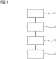
- FIG. 1 An embodiment of a method of operating an injection system of a motor vehicle is shown in figure 1 by means of a flow chart.
- a first step 1 the angular start (SOI) and timing (TI) of several injection pulses within an injection window are determined.
- the several injection pulses within an injection window comprise one or more pilot injections, one or more main injections and/or one or more post injections.
- angular start (SOI) corrections to the determined values (SOI, TI) from step 1 are carried out by a collision management (CM) rule based mechanism if there are conflicts between the several injection pulses.
- CM collision management
- step 3 the applied corrections for each start of an injection pulse are evaluated every step (shown at step 3).
- the evaluation is carried out with respect to pressure wave influences upon following injection pulses within the injection window.
- a fourth step the recalculated angular start (SOI) and timing (TI) are evaluated on the basis of minimum hydraulic separation (distance) between injection pulses and fitting of the injection pulses inside the injection window.
- SOI angular start
- TI timing
- the carried out evaluation (step 3) consists of comparing the corrections with a minimal threshold above which a carried out correction has a hydraulic influence on following injection pulses. If the result of the comparison lies above the threshold, the following injection timings are recalculated using the new pressure wave information.
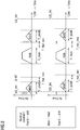
- Figure 2 shows a first scenario with regard to realizing the inventive method.
- the injection window is limited by SOI_lim and EOI_lim.
- the minimal hydraulic separation (distance) is characterized by T_Hyd_min.
- pilot 0 is shifted to the right because it is outside the injection window and it is enough space until SOI of main pulse.
- Post pulse is shifted to the right to keep minimal hydraulic separation. TIs are recalculated based on new pressure wave estimation.
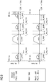
- pulse 2 needs to be shifted to the left because it is outside the injection window. Due to a lack of space even if the decision constraint allows shifting pulse 2, the SOI cannot be shifted more to the left, so the pulse is deleted. TI is recalculated based on new pressure wave estimation.
- pilot 2 should be moved because min hydraulic separation with main injection is violated. Due to decision constraint, pilot 2 cannot be shifted so the pulse is deleted. TI is recalculated based on new pressure wave estimation.
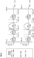
- post 2 needs to be shifted to the left because it is outside the injection window but there is not enough space.
- Post 1 can be shifted to the left because it is enough space to keep minimal hydraulic separation.
- this shift post 2 can be executed completely. TIs are recalculated based on new pressure wave estimation.
Landscapes
- Engineering & Computer Science (AREA)
- Chemical & Material Sciences (AREA)
- Combustion & Propulsion (AREA)
- Mechanical Engineering (AREA)
- General Engineering & Computer Science (AREA)
- Fuel-Injection Apparatus (AREA)
- Electrical Control Of Air Or Fuel Supplied To Internal-Combustion Engine (AREA)
Abstract
Description
- The present invention is directed to a method of operating an injection system of a motor vehicle.
- According to such an injection system several injection pulses are generated within an injection window. For determining the correct injection of fuel the angular start of injection (SOI) and the injection pulse timing (TI) have to be calculated. According to the existing systems these values are calculated without considering the hydraulic influences on the following injections for the requested configuration. After calculation of injection pulse timings (TI), corresponding corrections are applied to the initially calculated injection angles. In case of conflict for the pulses positioning - conflicts between the several injections within the injection window -, a collision management (CM) rule based mechanism decides upon the necessary actions, namely shift pulses, remove pulses etc.
- The injection systems for combustion engines work with a multitude of injection pulse configurations, at various SOIs, which need to be realized by considering the systems hydraulic and electrical constraints. Often, the requested injection pulses overlap and they need to be redistributed. Unfortunately, the redistribution of hydraulic injection pulses leads to a change in the hydraulic behaviour of the system which further could change the fuel pressure for following injections, requiring a recalculation of TIs. However, this recalculation is not realized in the current state of the art.
- It is the object of the present invention to provide a method of operating an injection system which is characterized by an especially high exactness.
- According to the invention this object is attained by a method of operating an injection system of a motor vehicle comprising the following steps:
- determining the angular start (SOI) and timing (TI) of several injection pulses within an injection window;
- carrying out corrections with the determined values by a collision management (CM) rule based mechanism upon conflicts between the injections pulses by shifting and/or removing pulses;
- when doing this, evaluating at every step the applied angular start of injection (SOI) corrections for each pulse with respect to pressure wave influences upon following injection pulses within the injection window; and
- recalculating the timing (TI) for following injection pulses on the basis of this evaluation, in order for the injection system to deliver the requested fuel mass for each injection pulse.
- Accordingly, if there are conflicts between the several injection pulses within the injection window when corrections are carried out by the collision management rule based mechanism, an evaluation is carried out with respect to the applied corrections if the corrections cause pressure wave influences upon following injection pulses. If such pressure wave influences exist, the injection timings are recalculated on the basis of this evaluation in order for the injection system to deliver the requested fuel mass.
- Thus, the inventive method allows an especially high exactness with respect to the operation of an injection system.
- So, the invention provides a method to manage collisions for injection pulses which gives the possibility to recalculate especially the injection pulses timings at each step using pressure wave corrections. These pressure wave corrections can be calculated on the basis of already redistributed predecessor start of injection angles and injection pulses timings.
- Preferably, the carried out evaluation consists of comparing the corrections with a minimal threshold above which a carried out correction has a hydraulic conflict on following injection pulses. According to the invention the impacted injection timings (TI) are recalculated if the result of the comparison lies above the threshold.
- Preferably, the method is characterized by comparing the corrections with a minimal threshold above which the start (SOI) of injection position change has a hydraulic influence on following injection pulses.
- The recalculation of start (SOI) and timing (TI) is preferably based on an iterative calculation method.
- According to an embodiment of the invention the electrical injection pulse timings are calculated from the determined hydraulic injection pulse timings (TI).
- As regards the corrections regarding the angular start of injection (SOI) and/or the injection pulse timings (TI), the same are preferably carried out to satisfy the constraints regarding minimum hydraulic separation (distance) between injection pulses and fitting of the injection pulses inside the injection window.
- The several injection pulses can be pulses of at least one pilot injection, main injection and/or post injection.
- The present invention is also directed to an injection system of a motor vehicle comprising a control unit configured to carry out the method according to one of the preceding claims.
- In the following the invention is described by means of examples in connection with the drawing:
- Figure 1
- shows a flow chart of the inventive method;
- Figure 2
- shows a first scenario with regard to the realization of the inventive method;
- Figure 3
- shows a second scenario with regard to the realization of the inventive method;
- Figure 4
- shows a third scenario with regard to the realization of the inventive method; and
- Figure 5
- shows a fourth scenario with regard to the realization of the inventive method.
- An embodiment of a method of operating an injection system of a motor vehicle is shown in
figure 1 by means of a flow chart. In afirst step 1 the angular start (SOI) and timing (TI) of several injection pulses within an injection window are determined. The several injection pulses within an injection window comprise one or more pilot injections, one or more main injections and/or one or more post injections. - In a second step angular start (SOI) corrections to the determined values (SOI, TI) from
step 1 are carried out by a collision management (CM) rule based mechanism if there are conflicts between the several injection pulses. These corrections comprise the shifting and/or removing of pulses. - By doing this the applied corrections for each start of an injection pulse are evaluated every step (shown at step 3). The evaluation is carried out with respect to pressure wave influences upon following injection pulses within the injection window.
- In a fourth step the recalculated angular start (SOI) and timing (TI) are evaluated on the basis of minimum hydraulic separation (distance) between injection pulses and fitting of the injection pulses inside the injection window. In case that the above mentioned constraints are not respected, the loop is restarted from
step 2. - The carried out evaluation (step 3) consists of comparing the corrections with a minimal threshold above which a carried out correction has a hydraulic influence on following injection pulses. If the result of the comparison lies above the threshold, the following injection timings are recalculated using the new pressure wave information.
- As regards the corrections carried out at
step 2 the same are carried out to satisfy the constraints regarding minimum hydraulic separation (distance) between injection pulses and fitting of the injection pulses inside the injection window. - The following algorithm with respect to the above-described method is described. The used terms have the following meanings:
- TI
- - injection pulse timing
- SOI
- - angular start of injection
- P
- - pressure wave compensation
- CM
- - collision management
- 1. Calculate intermediate hydraulic Tis for all active injections. Initialization: k = 1
- 2. Calculate pressure wave compensations Pk-1 for all injections using initial SOIk-1 and TIk-1
- 3. Recalculate new hydraulic TIs for all active injections using new pressure compensation => TIk
- 4. For i = 1...n Do
- Evaluate with hydraulic CM the requested hydraulic SOIs using intermediate TIk=> new hydraulic SOIs (to calculate correction SOIk - SOIk-1)
If |SOIk(i) - SOIk-1(i)| > minimum threshold, then: - , For injection i calculate pressure wave compensations Pk(i) from previous active injections using SOIk, and TIk
- , Recalculate hydraulic TI (TIk+1 (i)) for injection i using new pressure compensation
- , Calculate pressure wave compensations for all active following injections (j = i+1,...,n) using new SOIk(i) and TIk(i)=> Pk(j)
- , For j = i+1...n if |Pk(j)-Pk-1(j)|> minimum threshold, then:
- , Recalculate hydraulic TI (TIk+1 (j)) for injection j using new pressure compensation
- , End loop
- , Iterate k
- End loop
- 5. Evaluate with electrical CM the requested electrical SOIs using the calculated electrical TIs.
-
Figure 2 shows a first scenario with regard to realizing the inventive method. The injection window is limited by SOI_lim and EOI_lim. There are one pilot pulse, one main pulse and one post pulse within the window. The minimal hydraulic separation (distance) is characterized by T_Hyd_min. - In this
case pilot 0 is shifted to the right because it is outside the injection window and it is enough space until SOI of main pulse. Post pulse is shifted to the right to keep minimal hydraulic separation. TIs are recalculated based on new pressure wave estimation. - According to the scenario shown in
figure 3 pulse 2 needs to be shifted to the left because it is outside the injection window. Due to a lack of space even if the decision constraint allows shiftingpulse 2, the SOI cannot be shifted more to the left, so the pulse is deleted. TI is recalculated based on new pressure wave estimation. - In the scenario of
figure 4 pilot 2 should be moved because min hydraulic separation with main injection is violated. Due to decision constraint,pilot 2 cannot be shifted so the pulse is deleted. TI is recalculated based on new pressure wave estimation. - In the scenario of
figure 5 post 2 needs to be shifted to the left because it is outside the injection window but there is not enough space.Post 1 can be shifted to the left because it is enough space to keep minimal hydraulic separation. With thisshift post 2 can be executed completely. TIs are recalculated based on new pressure wave estimation.
Claims (8)
- A method of operating an injection system of a motor vehicle, said method comprising the following steps:determining the angular start (SOI) and timing (TI) of several injection pulses within an injection window;carrying out corrections with the determined values by a collision management (CM) rule based mechanism upon conflicts between the injections pulses by shifting and/or removing pulses;when doing this, evaluating at every step the applied angular start of injection (SOI) corrections for each pulse with respect to pressure wave influences upon following injection pulses within the injection window; andrecalculating the timing (TI) for following injection pulses on the basis of this evaluation, in order for the injection system to deliver the requested fuel mass for each injection pulse.
- The method according to claim 1, characterized in that the carried out evaluation consists of comparing the corrections with a minimal threshold above which a carried out correction has a hydraulic influence on following injection pulses and recalculating timing (TI) for following injection pulses if the result of the comparison lies above the threshold.
- The method according to claim 2 characterized by comparing the corrections with a minimal threshold above which the start (SOI) of injection position change has a hydraulic influence on following injection pulses.
- The method according to one of the preceding claims, characterized in that the recalculation of start (SOI) and timing (TI) is based on an iterative calculation method.
- The method according to one of the preceding claims, characterized by calculating the electrical injection pulse timings from the determined hydraulic injection pulse timings (TI).
- The method according to one of the preceding claims, characterized in that the corrections regarding the angular start of injection (SOI) and/or the injection pulse timings (TI) are carried out to satisfy the constraints regarding minimum hydraulic separation (distance) between injection pulses and fitting of the injection pulses inside the injection windows.
- The method according to one of the preceding claims, characterized in that the several injection pulses are pulses of at least one pilot injection, main injection and/or post injection.
- An injection system of a motor vehicle comprising an electronic control unit configured to carry out the method according to one of the preceding claims.
Priority Applications (1)
| Application Number | Priority Date | Filing Date | Title |
|---|---|---|---|
| EP16465537.5A EP3296550B8 (en) | 2016-09-19 | 2016-09-19 | Method of operating a multi-pulse injection system |
Applications Claiming Priority (1)
| Application Number | Priority Date | Filing Date | Title |
|---|---|---|---|
| EP16465537.5A EP3296550B8 (en) | 2016-09-19 | 2016-09-19 | Method of operating a multi-pulse injection system |
Publications (3)
| Publication Number | Publication Date |
|---|---|
| EP3296550A1 true EP3296550A1 (en) | 2018-03-21 |
| EP3296550B1 EP3296550B1 (en) | 2019-09-11 |
| EP3296550B8 EP3296550B8 (en) | 2019-12-18 |
Family
ID=57233368
Family Applications (1)
| Application Number | Title | Priority Date | Filing Date |
|---|---|---|---|
| EP16465537.5A Active EP3296550B8 (en) | 2016-09-19 | 2016-09-19 | Method of operating a multi-pulse injection system |
Country Status (1)
| Country | Link |
|---|---|
| EP (1) | EP3296550B8 (en) |
Citations (9)
| Publication number | Priority date | Publication date | Assignee | Title |
|---|---|---|---|---|
| US20070056563A1 (en) * | 2005-08-02 | 2007-03-15 | Sebastian Kanne | Method for controlling an injection system of an internal combustion engine |
| US20090063013A1 (en) * | 2007-08-31 | 2009-03-05 | Denso Corporation | Fuel injection characteristic sensing device and fuel injection command correcting device |
| US20090222195A1 (en) * | 2008-01-28 | 2009-09-03 | Gm Global Technology Operations, Inc. | Method for controlling two consecutive injection pulses in an electrically-actuated fuel injector system for an internal combustion engine, particularly a diesel engine |
| US20090234558A1 (en) * | 2006-04-12 | 2009-09-17 | Delphi Technologoes, Inc. | Fuel Injector Control Method |
| US20100318275A1 (en) * | 2007-11-09 | 2010-12-16 | Fredrik Borchsenius | Method and device for determining a vibration-optimised adjustment of an injection device |
| US20120035833A1 (en) * | 2010-08-03 | 2012-02-09 | GM Global Technology Operations LLC | Method for estimating an hydraulic dwell time between two injection pulses of a fuel injector |
| US20120130620A1 (en) * | 2010-11-18 | 2012-05-24 | GM Global Technology Operations LLC | Method for estimating an instantaneous pressure value in a fuel line of a fuel injection system |
| US20150088403A1 (en) * | 2013-09-23 | 2015-03-26 | GM Global Technology Operations LLC | Control apparatus for operating a fuel injector |
| GB2525604A (en) * | 2014-04-28 | 2015-11-04 | Gm Global Tech Operations Inc | Method of operating a fuel injector of a three-cylinder internal combustion engine |
Family Cites Families (1)
| Publication number | Priority date | Publication date | Assignee | Title |
|---|---|---|---|---|
| FR3030632B1 (en) * | 2014-12-22 | 2018-01-26 | Continental Automotive France | PROCESS FOR INDIRECT FUEL INJECTION FOR AN INTERNAL COMBUSTION ENGINE, INCLUDING CUTTING THE INJECTED FUEL QUANTITY |
-
2016
- 2016-09-19 EP EP16465537.5A patent/EP3296550B8/en active Active
Patent Citations (9)
| Publication number | Priority date | Publication date | Assignee | Title |
|---|---|---|---|---|
| US20070056563A1 (en) * | 2005-08-02 | 2007-03-15 | Sebastian Kanne | Method for controlling an injection system of an internal combustion engine |
| US20090234558A1 (en) * | 2006-04-12 | 2009-09-17 | Delphi Technologoes, Inc. | Fuel Injector Control Method |
| US20090063013A1 (en) * | 2007-08-31 | 2009-03-05 | Denso Corporation | Fuel injection characteristic sensing device and fuel injection command correcting device |
| US20100318275A1 (en) * | 2007-11-09 | 2010-12-16 | Fredrik Borchsenius | Method and device for determining a vibration-optimised adjustment of an injection device |
| US20090222195A1 (en) * | 2008-01-28 | 2009-09-03 | Gm Global Technology Operations, Inc. | Method for controlling two consecutive injection pulses in an electrically-actuated fuel injector system for an internal combustion engine, particularly a diesel engine |
| US20120035833A1 (en) * | 2010-08-03 | 2012-02-09 | GM Global Technology Operations LLC | Method for estimating an hydraulic dwell time between two injection pulses of a fuel injector |
| US20120130620A1 (en) * | 2010-11-18 | 2012-05-24 | GM Global Technology Operations LLC | Method for estimating an instantaneous pressure value in a fuel line of a fuel injection system |
| US20150088403A1 (en) * | 2013-09-23 | 2015-03-26 | GM Global Technology Operations LLC | Control apparatus for operating a fuel injector |
| GB2525604A (en) * | 2014-04-28 | 2015-11-04 | Gm Global Tech Operations Inc | Method of operating a fuel injector of a three-cylinder internal combustion engine |
Non-Patent Citations (1)
| Title |
|---|
| HANNU JÄÄSKELÄINEN ET AL: "Common Rail Fuel Injection", DIESELNET, 1 May 2015 (2015-05-01), XP055352640, Retrieved from the Internet <URL:https://www.dieselnet.com/tech/diesel_fi_common-rail.php> [retrieved on 20170308] * |
Also Published As
| Publication number | Publication date |
|---|---|
| EP3296550B1 (en) | 2019-09-11 |
| EP3296550B8 (en) | 2019-12-18 |
Similar Documents
| Publication | Publication Date | Title |
|---|---|---|
| CN110619307B (en) | Traffic light state determination method, device, equipment and storage medium | |
| US10460603B2 (en) | Method for providing obstacle maps for vehicles | |
| CN112912291B (en) | Method for planning a parking maneuver supported by a parking assistance system | |
| EP2846320A1 (en) | Single cycle offset adjustment for traffic signal controllers | |
| CN110775112A (en) | Real-time train operation diagram adjusting method and system | |
| EP3748297B1 (en) | Processing method and processing apparatus for positioning data, computing device and storage medium | |
| JP4552899B2 (en) | Fuel injection control device | |
| KR101509958B1 (en) | Device for correction an injector characteristic | |
| EP3296550A1 (en) | Method of operating a multi-pulse injection system | |
| US20220185321A1 (en) | An on-board control system for operating a vehicle | |
| US10642259B2 (en) | Method for operating a control unit of a motor vehicle | |
| US11359572B2 (en) | Method for learning emergency injection correction of injector for preventing misfire | |
| JP6333437B1 (en) | Object recognition processing device, object recognition processing method, and vehicle control system | |
| CN109543225B (en) | Vehicle control scheme generation method and device, storage medium and electronic equipment | |
| US20170082984A1 (en) | Electronic control device | |
| US20240384996A1 (en) | Vehicle control device and vehicle control method | |
| JP6041547B2 (en) | Tracking device | |
| KR20110062837A (en) | Angle control method, angle control device and automatic parking system using the same | |
| US12227177B2 (en) | Vehicle control device and vehicle control method | |
| CN107066004A (en) | For the method for the voltage for controlling to install device in the motor vehicle | |
| CN116771528A (en) | Fuel switching control method and device, electronic equipment and medium | |
| CN113494938B (en) | Object recognition device and object recognition method | |
| US20220128680A1 (en) | Method and Apparatus for Sensor Data Fusion for a Vehicle | |
| WO2018010899A1 (en) | Data processing method | |
| US20240046110A1 (en) | Multi-agent-based reinforcement learning system and method therefor |
Legal Events
| Date | Code | Title | Description |
|---|---|---|---|
| PUAI | Public reference made under article 153(3) epc to a published international application that has entered the european phase |
Free format text: ORIGINAL CODE: 0009012 |
|
| STAA | Information on the status of an ep patent application or granted ep patent |
Free format text: STATUS: THE APPLICATION HAS BEEN PUBLISHED |
|
| AK | Designated contracting states |
Kind code of ref document: A1 Designated state(s): AL AT BE BG CH CY CZ DE DK EE ES FI FR GB GR HR HU IE IS IT LI LT LU LV MC MK MT NL NO PL PT RO RS SE SI SK SM TR |
|
| AX | Request for extension of the european patent |
Extension state: BA ME |
|
| STAA | Information on the status of an ep patent application or granted ep patent |
Free format text: STATUS: REQUEST FOR EXAMINATION WAS MADE |
|
| 17P | Request for examination filed |
Effective date: 20180921 |
|
| RBV | Designated contracting states (corrected) |
Designated state(s): AL AT BE BG CH CY CZ DE DK EE ES FI FR GB GR HR HU IE IS IT LI LT LU LV MC MK MT NL NO PL PT RO RS SE SI SK SM TR |
|
| GRAP | Despatch of communication of intention to grant a patent |
Free format text: ORIGINAL CODE: EPIDOSNIGR1 |
|
| STAA | Information on the status of an ep patent application or granted ep patent |
Free format text: STATUS: GRANT OF PATENT IS INTENDED |
|
| INTG | Intention to grant announced |
Effective date: 20190404 |
|
| GRAS | Grant fee paid |
Free format text: ORIGINAL CODE: EPIDOSNIGR3 |
|
| GRAA | (expected) grant |
Free format text: ORIGINAL CODE: 0009210 |
|
| STAA | Information on the status of an ep patent application or granted ep patent |
Free format text: STATUS: THE PATENT HAS BEEN GRANTED |
|
| AK | Designated contracting states |
Kind code of ref document: B1 Designated state(s): AL AT BE BG CH CY CZ DE DK EE ES FI FR GB GR HR HU IE IS IT LI LT LU LV MC MK MT NL NO PL PT RO RS SE SI SK SM TR |
|
| REG | Reference to a national code |
Ref country code: GB Ref legal event code: FG4D |
|
| REG | Reference to a national code |
Ref country code: CH Ref legal event code: EP |
|
| REG | Reference to a national code |
Ref country code: AT Ref legal event code: REF Ref document number: 1178764 Country of ref document: AT Kind code of ref document: T Effective date: 20190915 |
|
| REG | Reference to a national code |
Ref country code: DE Ref legal event code: R096 Ref document number: 602016020329 Country of ref document: DE Ref country code: IE Ref legal event code: FG4D |
|
| REG | Reference to a national code |
Ref country code: CH Ref legal event code: PK Free format text: BERICHTIGUNG B8 Ref country code: DE Ref legal event code: R081 Ref document number: 602016020329 Country of ref document: DE Owner name: VITESCO TECHNOLOGIES GMBH, DE Free format text: FORMER OWNER: CONTINENTAL AUTOMOTIVE GMBH, 30165 HANNOVER, DE |
|
| REG | Reference to a national code |
Ref country code: RO Ref legal event code: EPE |
|
| RAP2 | Party data changed (patent owner data changed or rights of a patent transferred) |
Owner name: CPT GROUP GMBH |
|
| RAP2 | Party data changed (patent owner data changed or rights of a patent transferred) |
Owner name: VITESCO TECHNOLOGIES GMBH |
|
| REG | Reference to a national code |
Ref country code: NL Ref legal event code: MP Effective date: 20190911 |
|
| REG | Reference to a national code |
Ref country code: DE Ref legal event code: R081 Ref document number: 602016020329 Country of ref document: DE Owner name: VITESCO TECHNOLOGIES GMBH, DE Free format text: FORMER OWNER: CPT GROUP GMBH, 30165 HANNOVER, DE |
|
| REG | Reference to a national code |
Ref country code: LT Ref legal event code: MG4D |
|
| PG25 | Lapsed in a contracting state [announced via postgrant information from national office to epo] |
Ref country code: BG Free format text: LAPSE BECAUSE OF FAILURE TO SUBMIT A TRANSLATION OF THE DESCRIPTION OR TO PAY THE FEE WITHIN THE PRESCRIBED TIME-LIMIT Effective date: 20191211 Ref country code: NO Free format text: LAPSE BECAUSE OF FAILURE TO SUBMIT A TRANSLATION OF THE DESCRIPTION OR TO PAY THE FEE WITHIN THE PRESCRIBED TIME-LIMIT Effective date: 20191211 Ref country code: SE Free format text: LAPSE BECAUSE OF FAILURE TO SUBMIT A TRANSLATION OF THE DESCRIPTION OR TO PAY THE FEE WITHIN THE PRESCRIBED TIME-LIMIT Effective date: 20190911 Ref country code: FI Free format text: LAPSE BECAUSE OF FAILURE TO SUBMIT A TRANSLATION OF THE DESCRIPTION OR TO PAY THE FEE WITHIN THE PRESCRIBED TIME-LIMIT Effective date: 20190911 Ref country code: LT Free format text: LAPSE BECAUSE OF FAILURE TO SUBMIT A TRANSLATION OF THE DESCRIPTION OR TO PAY THE FEE WITHIN THE PRESCRIBED TIME-LIMIT Effective date: 20190911 Ref country code: HR Free format text: LAPSE BECAUSE OF FAILURE TO SUBMIT A TRANSLATION OF THE DESCRIPTION OR TO PAY THE FEE WITHIN THE PRESCRIBED TIME-LIMIT Effective date: 20190911 |
|
| PG25 | Lapsed in a contracting state [announced via postgrant information from national office to epo] |
Ref country code: ES Free format text: LAPSE BECAUSE OF FAILURE TO SUBMIT A TRANSLATION OF THE DESCRIPTION OR TO PAY THE FEE WITHIN THE PRESCRIBED TIME-LIMIT Effective date: 20190911 Ref country code: AL Free format text: LAPSE BECAUSE OF FAILURE TO SUBMIT A TRANSLATION OF THE DESCRIPTION OR TO PAY THE FEE WITHIN THE PRESCRIBED TIME-LIMIT Effective date: 20190911 Ref country code: GR Free format text: LAPSE BECAUSE OF FAILURE TO SUBMIT A TRANSLATION OF THE DESCRIPTION OR TO PAY THE FEE WITHIN THE PRESCRIBED TIME-LIMIT Effective date: 20191212 Ref country code: RS Free format text: LAPSE BECAUSE OF FAILURE TO SUBMIT A TRANSLATION OF THE DESCRIPTION OR TO PAY THE FEE WITHIN THE PRESCRIBED TIME-LIMIT Effective date: 20190911 Ref country code: LV Free format text: LAPSE BECAUSE OF FAILURE TO SUBMIT A TRANSLATION OF THE DESCRIPTION OR TO PAY THE FEE WITHIN THE PRESCRIBED TIME-LIMIT Effective date: 20190911 |
|
| REG | Reference to a national code |
Ref country code: AT Ref legal event code: MK05 Ref document number: 1178764 Country of ref document: AT Kind code of ref document: T Effective date: 20190911 |
|
| PG25 | Lapsed in a contracting state [announced via postgrant information from national office to epo] |
Ref country code: PT Free format text: LAPSE BECAUSE OF FAILURE TO SUBMIT A TRANSLATION OF THE DESCRIPTION OR TO PAY THE FEE WITHIN THE PRESCRIBED TIME-LIMIT Effective date: 20200113 Ref country code: PL Free format text: LAPSE BECAUSE OF FAILURE TO SUBMIT A TRANSLATION OF THE DESCRIPTION OR TO PAY THE FEE WITHIN THE PRESCRIBED TIME-LIMIT Effective date: 20190911 Ref country code: NL Free format text: LAPSE BECAUSE OF FAILURE TO SUBMIT A TRANSLATION OF THE DESCRIPTION OR TO PAY THE FEE WITHIN THE PRESCRIBED TIME-LIMIT Effective date: 20190911 Ref country code: IT Free format text: LAPSE BECAUSE OF FAILURE TO SUBMIT A TRANSLATION OF THE DESCRIPTION OR TO PAY THE FEE WITHIN THE PRESCRIBED TIME-LIMIT Effective date: 20190911 Ref country code: AT Free format text: LAPSE BECAUSE OF FAILURE TO SUBMIT A TRANSLATION OF THE DESCRIPTION OR TO PAY THE FEE WITHIN THE PRESCRIBED TIME-LIMIT Effective date: 20190911 Ref country code: EE Free format text: LAPSE BECAUSE OF FAILURE TO SUBMIT A TRANSLATION OF THE DESCRIPTION OR TO PAY THE FEE WITHIN THE PRESCRIBED TIME-LIMIT Effective date: 20190911 |
|
| PG25 | Lapsed in a contracting state [announced via postgrant information from national office to epo] |
Ref country code: SM Free format text: LAPSE BECAUSE OF FAILURE TO SUBMIT A TRANSLATION OF THE DESCRIPTION OR TO PAY THE FEE WITHIN THE PRESCRIBED TIME-LIMIT Effective date: 20190911 Ref country code: CZ Free format text: LAPSE BECAUSE OF FAILURE TO SUBMIT A TRANSLATION OF THE DESCRIPTION OR TO PAY THE FEE WITHIN THE PRESCRIBED TIME-LIMIT Effective date: 20190911 Ref country code: SK Free format text: LAPSE BECAUSE OF FAILURE TO SUBMIT A TRANSLATION OF THE DESCRIPTION OR TO PAY THE FEE WITHIN THE PRESCRIBED TIME-LIMIT Effective date: 20190911 Ref country code: IS Free format text: LAPSE BECAUSE OF FAILURE TO SUBMIT A TRANSLATION OF THE DESCRIPTION OR TO PAY THE FEE WITHIN THE PRESCRIBED TIME-LIMIT Effective date: 20200224 |
|
| REG | Reference to a national code |
Ref country code: CH Ref legal event code: PL |
|
| REG | Reference to a national code |
Ref country code: DE Ref legal event code: R097 Ref document number: 602016020329 Country of ref document: DE |
|
| PLBE | No opposition filed within time limit |
Free format text: ORIGINAL CODE: 0009261 |
|
| STAA | Information on the status of an ep patent application or granted ep patent |
Free format text: STATUS: NO OPPOSITION FILED WITHIN TIME LIMIT |
|
| PG2D | Information on lapse in contracting state deleted |
Ref country code: IS |
|
| PG25 | Lapsed in a contracting state [announced via postgrant information from national office to epo] |
Ref country code: CH Free format text: LAPSE BECAUSE OF NON-PAYMENT OF DUE FEES Effective date: 20190930 Ref country code: DK Free format text: LAPSE BECAUSE OF FAILURE TO SUBMIT A TRANSLATION OF THE DESCRIPTION OR TO PAY THE FEE WITHIN THE PRESCRIBED TIME-LIMIT Effective date: 20190911 Ref country code: LI Free format text: LAPSE BECAUSE OF NON-PAYMENT OF DUE FEES Effective date: 20190930 Ref country code: LU Free format text: LAPSE BECAUSE OF NON-PAYMENT OF DUE FEES Effective date: 20190919 Ref country code: IE Free format text: LAPSE BECAUSE OF NON-PAYMENT OF DUE FEES Effective date: 20190919 Ref country code: IS Free format text: LAPSE BECAUSE OF FAILURE TO SUBMIT A TRANSLATION OF THE DESCRIPTION OR TO PAY THE FEE WITHIN THE PRESCRIBED TIME-LIMIT Effective date: 20200112 |
|
| REG | Reference to a national code |
Ref country code: BE Ref legal event code: MM Effective date: 20190930 |
|
| 26N | No opposition filed |
Effective date: 20200615 |
|
| PG25 | Lapsed in a contracting state [announced via postgrant information from national office to epo] |
Ref country code: BE Free format text: LAPSE BECAUSE OF NON-PAYMENT OF DUE FEES Effective date: 20190930 Ref country code: MC Free format text: LAPSE BECAUSE OF FAILURE TO SUBMIT A TRANSLATION OF THE DESCRIPTION OR TO PAY THE FEE WITHIN THE PRESCRIBED TIME-LIMIT Effective date: 20190911 Ref country code: SI Free format text: LAPSE BECAUSE OF FAILURE TO SUBMIT A TRANSLATION OF THE DESCRIPTION OR TO PAY THE FEE WITHIN THE PRESCRIBED TIME-LIMIT Effective date: 20190911 |
|
| GBPC | Gb: european patent ceased through non-payment of renewal fee |
Effective date: 20200919 |
|
| PG25 | Lapsed in a contracting state [announced via postgrant information from national office to epo] |
Ref country code: CY Free format text: LAPSE BECAUSE OF FAILURE TO SUBMIT A TRANSLATION OF THE DESCRIPTION OR TO PAY THE FEE WITHIN THE PRESCRIBED TIME-LIMIT Effective date: 20190911 |
|
| PG25 | Lapsed in a contracting state [announced via postgrant information from national office to epo] |
Ref country code: HU Free format text: LAPSE BECAUSE OF FAILURE TO SUBMIT A TRANSLATION OF THE DESCRIPTION OR TO PAY THE FEE WITHIN THE PRESCRIBED TIME-LIMIT; INVALID AB INITIO Effective date: 20160919 Ref country code: MT Free format text: LAPSE BECAUSE OF FAILURE TO SUBMIT A TRANSLATION OF THE DESCRIPTION OR TO PAY THE FEE WITHIN THE PRESCRIBED TIME-LIMIT Effective date: 20190911 |
|
| PG25 | Lapsed in a contracting state [announced via postgrant information from national office to epo] |
Ref country code: GB Free format text: LAPSE BECAUSE OF NON-PAYMENT OF DUE FEES Effective date: 20200919 |
|
| REG | Reference to a national code |
Ref country code: DE Ref legal event code: R081 Ref document number: 602016020329 Country of ref document: DE Owner name: SCHAEFFLER TECHNOLOGIES AG & CO. KG, DE Free format text: FORMER OWNER: VITESCO TECHNOLOGIES GMBH, 30165 HANNOVER, DE Ref country code: DE Ref legal event code: R081 Ref document number: 602016020329 Country of ref document: DE Owner name: VITESCO TECHNOLOGIES GMBH, DE Free format text: FORMER OWNER: VITESCO TECHNOLOGIES GMBH, 30165 HANNOVER, DE |
|
| PG25 | Lapsed in a contracting state [announced via postgrant information from national office to epo] |
Ref country code: TR Free format text: LAPSE BECAUSE OF FAILURE TO SUBMIT A TRANSLATION OF THE DESCRIPTION OR TO PAY THE FEE WITHIN THE PRESCRIBED TIME-LIMIT Effective date: 20190911 |
|
| PG25 | Lapsed in a contracting state [announced via postgrant information from national office to epo] |
Ref country code: MK Free format text: LAPSE BECAUSE OF FAILURE TO SUBMIT A TRANSLATION OF THE DESCRIPTION OR TO PAY THE FEE WITHIN THE PRESCRIBED TIME-LIMIT Effective date: 20190911 |
|
| P01 | Opt-out of the competence of the unified patent court (upc) registered |
Effective date: 20230530 |
|
| REG | Reference to a national code |
Ref country code: DE Ref legal event code: R081 Ref document number: 602016020329 Country of ref document: DE Owner name: SCHAEFFLER TECHNOLOGIES AG & CO. KG, DE Free format text: FORMER OWNER: VITESCO TECHNOLOGIES GMBH, 93055 REGENSBURG, DE |
|
| PGFP | Annual fee paid to national office [announced via postgrant information from national office to epo] |
Ref country code: DE Payment date: 20250930 Year of fee payment: 10 |
|
| PGFP | Annual fee paid to national office [announced via postgrant information from national office to epo] |
Ref country code: FR Payment date: 20250922 Year of fee payment: 10 |
|
| PGFP | Annual fee paid to national office [announced via postgrant information from national office to epo] |
Ref country code: RO Payment date: 20250916 Year of fee payment: 10 |