EP3296519A1 - Flowpath component for a gas turbine engine including a chordal seal - Google Patents
Flowpath component for a gas turbine engine including a chordal seal Download PDFInfo
- Publication number
- EP3296519A1 EP3296519A1 EP17191286.8A EP17191286A EP3296519A1 EP 3296519 A1 EP3296519 A1 EP 3296519A1 EP 17191286 A EP17191286 A EP 17191286A EP 3296519 A1 EP3296519 A1 EP 3296519A1
- Authority
- EP
- European Patent Office
- Prior art keywords
- flow path
- face
- path component
- radially aligned
- chordal seal
- Prior art date
- Legal status (The legal status is an assumption and is not a legal conclusion. Google has not performed a legal analysis and makes no representation as to the accuracy of the status listed.)
- Granted
Links
Images

Classifications
-
- F—MECHANICAL ENGINEERING; LIGHTING; HEATING; WEAPONS; BLASTING
- F01—MACHINES OR ENGINES IN GENERAL; ENGINE PLANTS IN GENERAL; STEAM ENGINES
- F01D—NON-POSITIVE DISPLACEMENT MACHINES OR ENGINES, e.g. STEAM TURBINES
- F01D11/00—Preventing or minimising internal leakage of working-fluid, e.g. between stages
- F01D11/005—Sealing means between non relatively rotating elements
-
- F—MECHANICAL ENGINEERING; LIGHTING; HEATING; WEAPONS; BLASTING
- F01—MACHINES OR ENGINES IN GENERAL; ENGINE PLANTS IN GENERAL; STEAM ENGINES
- F01D—NON-POSITIVE DISPLACEMENT MACHINES OR ENGINES, e.g. STEAM TURBINES
- F01D11/00—Preventing or minimising internal leakage of working-fluid, e.g. between stages
- F01D11/001—Preventing or minimising internal leakage of working-fluid, e.g. between stages for sealing space between stator blade and rotor
-
- F—MECHANICAL ENGINEERING; LIGHTING; HEATING; WEAPONS; BLASTING
- F01—MACHINES OR ENGINES IN GENERAL; ENGINE PLANTS IN GENERAL; STEAM ENGINES
- F01D—NON-POSITIVE DISPLACEMENT MACHINES OR ENGINES, e.g. STEAM TURBINES
- F01D5/00—Blades; Blade-carrying members; Heating, heat-insulating, cooling or antivibration means on the blades or the members
- F01D5/02—Blade-carrying members, e.g. rotors
- F01D5/06—Rotors for more than one axial stage, e.g. of drum or multiple disc type; Details thereof, e.g. shafts, shaft connections
-
- F—MECHANICAL ENGINEERING; LIGHTING; HEATING; WEAPONS; BLASTING
- F01—MACHINES OR ENGINES IN GENERAL; ENGINE PLANTS IN GENERAL; STEAM ENGINES
- F01D—NON-POSITIVE DISPLACEMENT MACHINES OR ENGINES, e.g. STEAM TURBINES
- F01D9/00—Stators
- F01D9/02—Nozzles; Nozzle boxes; Stator blades; Guide conduits, e.g. individual nozzles
- F01D9/04—Nozzles; Nozzle boxes; Stator blades; Guide conduits, e.g. individual nozzles forming ring or sector
- F01D9/041—Nozzles; Nozzle boxes; Stator blades; Guide conduits, e.g. individual nozzles forming ring or sector using blades
-
- F—MECHANICAL ENGINEERING; LIGHTING; HEATING; WEAPONS; BLASTING
- F02—COMBUSTION ENGINES; HOT-GAS OR COMBUSTION-PRODUCT ENGINE PLANTS
- F02C—GAS-TURBINE PLANTS; AIR INTAKES FOR JET-PROPULSION PLANTS; CONTROLLING FUEL SUPPLY IN AIR-BREATHING JET-PROPULSION PLANTS
- F02C3/00—Gas-turbine plants characterised by the use of combustion products as the working fluid
- F02C3/04—Gas-turbine plants characterised by the use of combustion products as the working fluid having a turbine driving a compressor
-
- F—MECHANICAL ENGINEERING; LIGHTING; HEATING; WEAPONS; BLASTING
- F05—INDEXING SCHEMES RELATING TO ENGINES OR PUMPS IN VARIOUS SUBCLASSES OF CLASSES F01-F04
- F05D—INDEXING SCHEME FOR ASPECTS RELATING TO NON-POSITIVE-DISPLACEMENT MACHINES OR ENGINES, GAS-TURBINES OR JET-PROPULSION PLANTS
- F05D2220/00—Application
- F05D2220/30—Application in turbines
- F05D2220/32—Application in turbines in gas turbines
-
- F—MECHANICAL ENGINEERING; LIGHTING; HEATING; WEAPONS; BLASTING
- F05—INDEXING SCHEMES RELATING TO ENGINES OR PUMPS IN VARIOUS SUBCLASSES OF CLASSES F01-F04
- F05D—INDEXING SCHEME FOR ASPECTS RELATING TO NON-POSITIVE-DISPLACEMENT MACHINES OR ENGINES, GAS-TURBINES OR JET-PROPULSION PLANTS
- F05D2240/00—Components
- F05D2240/35—Combustors or associated equipment
-
- F—MECHANICAL ENGINEERING; LIGHTING; HEATING; WEAPONS; BLASTING
- F05—INDEXING SCHEMES RELATING TO ENGINES OR PUMPS IN VARIOUS SUBCLASSES OF CLASSES F01-F04
- F05D—INDEXING SCHEME FOR ASPECTS RELATING TO NON-POSITIVE-DISPLACEMENT MACHINES OR ENGINES, GAS-TURBINES OR JET-PROPULSION PLANTS
- F05D2240/00—Components
- F05D2240/55—Seals
-
- F—MECHANICAL ENGINEERING; LIGHTING; HEATING; WEAPONS; BLASTING
- F05—INDEXING SCHEMES RELATING TO ENGINES OR PUMPS IN VARIOUS SUBCLASSES OF CLASSES F01-F04
- F05D—INDEXING SCHEME FOR ASPECTS RELATING TO NON-POSITIVE-DISPLACEMENT MACHINES OR ENGINES, GAS-TURBINES OR JET-PROPULSION PLANTS
- F05D2250/00—Geometry
- F05D2250/70—Shape
- F05D2250/71—Shape curved
Definitions
- the present disclosure relates generally to flowpath components for gas powered turbines, and more specifically to a flowpath component including a chordal seal.
- Gas powered turbines generally include a compressor section that draws in and compresses air, a combustor section where the compressed air is mixed with a fuel and ignited, and a turbine section across which the resultant combustion products are expanded. The expansion of the combustion products drives the turbine to rotate, which in turn drives the compressor.
- Gas flow through the primary flowpath is controlled and directed by multiple flowpath spanning components.
- seals are typically incorporated into one or more of the flowpath component surfaces. The seals prevent leakage between the inner and outer diameter portions of the flowpath spanning components and adjacent components defining the inner and outer diameter walls of the flowpath.
- the relative positions of flowpath components can shift due to various mechanical stresses and thermal expansions and contractions.
- the relative position shift is referred to as deflection and can cause certain types and configurations of seals to misalign, allowing leakage from the flow path through the seals designed to prevent leakage.
- a flow path component includes a platform including at least one radially aligned face, a chordal seal extending axially from the radially aligned face, and wherein the chordal seal includes a first curved face configured to prevent edge line contact under deflection conditions while the flow path component is installed in an engine.
- the radius of curvature of the first curved face is in the range of 0.3 to 0.7 inches (0.76 to 1.78 centimeters).
- the radius of curvature of the first curved face is approximately 0.5 inches (1.27 centimeters).
- chordal seal includes at least one clearance cut intrusion protruding into the chordal seal.
- the at least one clearance cut intrusion has a radially outward facing radius of curvature.
- the radially outward facing radius of curvature is in the range of 7.0 to 7.6 inches (17.78 to 19.30 centimeters).
- the radially outward facing radius of curvature is in the range of 7.2 to 7.4 inches (18.29 to 18.80 centimeters).
- the radially outward facing radius of curvature is approximately 7.3 inches (18.6 centimeters).
- a peak of the first curved face is approximately 10 inches (25.4 centimeters) from a centerline of the engine, while the flow path component is in an installed state.
- Another exemplary embodiment of any of the above described flow path components further includes a second platform radially opposite the first platform and connected to the first platform via a flowpath body, the second platform including a second radially aligned face and a second chordal seal extending axially from the second radially aligned face.
- the second chordal seal includes a second first curved face having a curvature approximately identical to the curvature of the first curved face.
- a distance between a peak of the first curved face and a peak of the second curved face is in the range of 2.2 to 2.6 inches (5.59 to 6.60 centimeters).
- the first platform includes a second radially aligned face opposite the first radially aligned face, wherein the second radially aligned face is a planar face.
- the second radially aligned face is forward facing and has an angle of between 85 and 95 degrees relative to a centerline of the engine, while the flow path component is in an installed state.
- the angle is approximately 90 degrees.
- the flowpath component is a first stage high pressure turbine vane.
- an edge line and a peak of the chordal seal are parallel.
- the first curved surface includes a planar contact surface.
- a gas turbine engine in one exemplary embodiment includes a compressor section, a combustor section fluidly connected to the compressor section, a turbine section fluidly connected to the combustor section, the turbine section including a plurality of turbine stages, each of the stages including a vane and a rotor, and wherein at least one of the vanes includes a platform including at least one radially aligned face, a chordal seal extending axially from the radially aligned face, and the chordal seal includes a first curved face configured to prevent edge line contact under deflection conditions while the flow path component is installed in an engine.
- An exemplary method for sealing a turbine flowpath during deflection conditions includes maintaining contact between a curved face of a first chordal seal of a first flowpath component and an adjacent first contact face of a second flowpath component, and maintaining contact between a curved face of a second chordal seal of the first flowpath component and an adjacent second contact face of the second flowpath component.
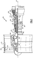
- FIG. 1 schematically illustrates a gas turbine engine 20.
- the gas turbine engine 20 is disclosed herein as a two-spool turbofan that generally incorporates a fan section 22, a compressor section 24, a combustor section 26 and a turbine section 28.
- Alternative engines might include an augmentor section (not shown) among other systems or features.
- the fan section 22 drives air along a bypass flow path B in a bypass duct defined within a nacelle 15, while the compressor section 24 drives air along a core flow path C for compression and communication into the combustor section 26 then expansion through the turbine section 28.
- gaspath component, and associated cooling system, described herein can be utilized in any gas powered turbine, including a land based turbine, a marine turbine, a test rig, or any other gas powered turbine construction.
- the exemplary engine 20 generally includes a low speed spool 30 and a high speed spool 32 mounted for rotation about an engine central longitudinal axis A relative to an engine static structure 36 via several bearing systems 38. It should be understood that various bearing systems 38 at various locations may alternatively or additionally be provided, and the location of bearing systems 38 may be varied as appropriate to the application.
- the low speed spool 30 generally includes an inner shaft 40 that interconnects a fan 42, a first (or low) pressure compressor 44 and a first (or low) pressure turbine 46.
- the inner shaft 40 is connected to the fan 42 through a speed change mechanism, which in exemplary gas turbine engine 20 is illustrated as a geared architecture 48 to drive the fan 42 at a lower speed than the low speed spool 30.
- the high speed spool 32 includes an outer shaft 50 that interconnects a second (or high) pressure compressor 52 and a second (or high) pressure turbine 54.
- a combustor 56 is arranged in exemplary gas turbine 20 between the high pressure compressor 52 and the high pressure turbine 54.
- a mid-turbine frame 57 of the engine static structure 36 is arranged generally between the high pressure turbine 54 and the low pressure turbine 46.
- the mid-turbine frame 57 further supports bearing systems 38 in the turbine section 28.
- the inner shaft 40 and the outer shaft 50 are concentric and rotate via bearing systems 38 about the engine central longitudinal axis A which is collinear with their longitudinal axes.
- the core airflow is compressed by the low pressure compressor 44 then the high pressure compressor 52, mixed and burned with fuel in the combustor 56, then expanded over the high pressure turbine 54 and low pressure turbine 46.
- the mid-turbine frame 57 includes airfoils 59 which are in the core airflow path C.
- the turbines 46, 54 rotationally drive the respective low speed spool 30 and high speed spool 32 in response to the expansion.
- gear system 48 may be located aft of combustor section 26 or even aft of turbine section 28, and fan section 22 may be positioned forward or aft of the location of gear system 48.
- the engine 20 in one example is a high-bypass geared aircraft engine.
- the engine 20 bypass ratio is greater than about six, with an example embodiment being greater than about ten
- the geared architecture 48 is an epicyclic gear train, such as a planetary gear system or other gear system, with a gear reduction ratio of greater than about 2.3 and the low pressure turbine 46 has a pressure ratio that is greater than about five.
- the engine 20 bypass ratio is greater than about ten
- the fan diameter is significantly larger than that of the low pressure compressor 44
- the low pressure turbine 46 has a pressure ratio that is greater than about five.
- Low pressure turbine 46 pressure ratio is pressure measured prior to inlet of low pressure turbine 46 as related to the pressure at the outlet of the low pressure turbine 46 prior to an exhaust nozzle.
- the geared architecture 48 may be an epicycle gear train, such as a planetary gear system or other gear system, with a gear reduction ratio of greater than about 2.3:1. It should be understood, however, that the above parameters are only exemplary of one embodiment of a geared architecture engine and that the present invention is applicable to other gas turbine engines including direct drive turbofans.
- the fan section 22 of the engine 20 is designed for a particular flight condition -- typically cruise at about 0.8 Mach and about 35,000 feet (10,668 meters).
- the flight condition of 0.8 Mach and 35,000 ft (10,668 m), with the engine at its best fuel consumption - also known as "bucket cruise Thrust Specific Fuel Consumption ('TSFC')" - is the industry standard parameter of lbm of fuel being burned divided by lbf of thrust the engine produces at that minimum point.
- "Low fan pressure ratio” is the pressure ratio across the fan blade alone, without a Fan Exit Guide Vane (“FEGV”) system.
- the low fan pressure ratio as disclosed herein according to one non-limiting embodiment is less than about 1.45.
- the "Low corrected fan tip speed” as disclosed herein according to one non-limiting embodiment is less than about 1150 ft / second (350.5 m/s).
- combustion products are provided from the combustor section 26 to the turbine section 28 along the primary flowpath.
- the turbine section 28 is constructed of multiple turbine stages, with each stage including a vane and a rotor. Within each stage, the flowpath is defined by an inner platform and an outer platform at the vane, and a blade platform and a blade outer air seal at the rotor. Each of the flowpath components is sealed to the adjacent flowpath components in order to prevent leakage of the combustion products from the flowpath, as leakage reduces the efficiency of engine operations.
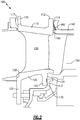
- Figure 2 schematically illustrates an example turbine vane 100 in a first stage of the turbine section 28 of the engine 20.
- the vane 100 includes a radially outer platform 110, a radially inner platform 120, and a flowpath body 130 spanning from the radially outer platform 110 to the radially inner platform 120.
- a blade outer air seal 140 Located downstream of the vane 100, on an outer diameter, is a blade outer air seal 140, and a rotor 150.
- the radially outer platform 110 includes a radial extension 112 with a radially aligned face 114. Axially opposite the first radial extension 112 is a second radial extension 115. The second radial extension has a second radially aligned face 117. Extending axially from the first radial face 114 is a chordal seal 160. The chordal seal 160 contacts a corresponding face of the adjacent blade outer air seal 140, and prevents leakage from the cooling flow cavity between the vane 100 and the blade outer air seal 140. The chordal seal 160 is an axial protrusion from the first radially aligned surface 114, and extends a full circumferential length of the platform 110.
- the chordal seal 160 includes a contact surface 162.
- the contact surface of the chordal seal 160 is curved. By curving contact surface 162, the seal is maintained when deflection occurs, and the relative positions of the vane 100 and the adjacent blade outer air seal 140 alter during engine operations.
- the radial position of the chordal seal 160 that is axially farthest from the surface 114 is referred to as the "peak" of the chordal seal 160.
- the radially outermost, and radially innermost portions of the chordal seal 160 are referred to as edge lines. In an exemplary nominal vane 100, the edge lines and the peak are parallel. In alternative implementations, the edge lines and the peak can be slightly off parallel.
- the radially inner platform 120 includes a radial extension 122 with a radially aligned face 124. Axially opposite the radial extension 122 is a second radial extension 125 having a second radially aligned face 126. Extending axially from the first radial face 124 is a second chordal seal 170.
- the second chordal seal 170 is substantially similar in both form and function to the first chordal seal 160, including the curved surface 172 contacting an adjacent flowpath component.
- the radial position of the chordal seal 170 that is axially farthest from the surface 114 is referred to as the "peak" of the chordal seal 170.
- the forward radially aligned faces 117, 126 each contact a corresponding outer diameter and inner diameter duct wall, such as a combustor duct, and form a contact seal, further enhancing the ability of the vane 100 to seal during various operating conditions.
- the combustor duct can be positioned further radially inward than the illustrated example.
- the corresponding chordal seals 160, 170 can include a planar contact surface at the peak, and the curved surface of the chordal seal is not a continuous curve.
- Figure 3 schematically illustrates one specific embodiment of the flow path component configuration (vane 100) of Figure 2 .
- the numerical values of the parameters are those of the vane 100 in an installed position in a non-operating (cold) engine.
- the peak of the first chordal seal 160 is separated from the peak of the second chordal seal 170 by a distance 210.
- the distance 210 is in the range of 2.2 inches to 2.6 inches (5.59 to 6.60 centimeters). In alternative examples the distance 210 is approximately 2.4 inches (6.1 centimeters), accounting for manufacturing tolerances.
- each of the chordal seals 160, 170 is defined in part by their radial distance 212, 214 from an engine centerline 220.
- the radial distance 212 of the outer chordal seal 160 is, in some examples, 10 inches (25.4 centimeters) from the engine centerline 220.
- the radial distance 214 of the inner chordal seal 170 is, in some examples, 7.4 inches (18.8 centimeters).
- each of the curved surfaces 162, 172 of the chordal seals 160, 170 is defined by a radius of curvature that protrudes away from the corresponding radially aligned surface 114, 124.
- the curved surfaces 162, 172 have, in some examples, a radius of curvature in the range of 0.3 to 0.7 inches (0.762 to 1.78 centimeters).
- the radius of curvature of the chordal seals 160, 170 is approximately 0.5 inches (1.27 centimeters), accounting for manufacturing tolerances.
- each of the chordal seals 160, 170 include approximately identical radiuses of curvature.
- the outer chordal seal 160 has a radial height 230 (length along the engine radius) in the range of 0.1 to 0.2 inches (0.25 to 0.51 centimeters). In further examples, the radial height 230 of the outer chordal seal 160 is approximately 0.1 inches (0.254 centimeters) accounting for manufacturing tolerances.
- the inner chordal seal 170 has a radial height 232 in the range of 0.1 to 0.2 inches (0.25 to 0.51 centimeters). In further examples, the radial height 232 of the inner chordal seal 170 is approximately 0.15 inches (0.381 centimeters), accounting for manufacturing tolerances.
- the second radially aligned face 117 of the outer platform 110 has a radial contact height 242 of approximate 0.3 inches (0.767 centimeters), accounting for manufacturing tolerances.
- the second radially aligned surface 126 of the inner platform 120 has a radial contact height 244 of approximately 0.3 inches (0.767 centimeters).
- the radially aligned surfaces 117, 127 at the contact points are positioned at an angle of between 85 and 95 degrees, relative to the engine centerline axis 220. In further examples, the radially aligned surfaces 117, 127 are positioned at an angle of approximately 90 degrees, relative to the engine centerline axis.
- Figure 4 schematically illustrates a zoomed view of an exemplary chordal seal connection 300, with certain elements of the chordal seal exaggerated for explanatory purposes.
- the chordal seal 300 protrudes from a radially aligned surface 310, and includes a curved surface 320, that has a radius of curvature protruding away from the radially aligned surface 310 parallel to an engine centerline axis.
- the curved surface 320 contacts a corresponding face 330 of an adjacent flowpath component at a contact point 322.
- the shifting contact point 322 is Due to the nature of the curved surface, as well as the sizing and relative positioning.
- the curvature of the curved surface 320 ensures that regardless of the magnitude of the deflection, a contact point 322 is maintained between the curved surface 320 and the adjacent component.
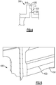
- Figure 5 illustrates an isometric view of an example chordal seal 400.
- the example chordal seal 400 is positioned on the radially inner platform (platform 120 in Figures 2 and 3 ), and seals against an adjacent sealing structure and a contact point 422 as described above.
- the isometric view illustrates a clearance cut intrusion 450 extending radially outward into the chordal seal 400.
- the clearance cut intrusion accommodates adjacent engine components, such as a turbine on board injector (TOBI) system, or the like.
- the clearance cut is a curved intrusion and the radius of curvature of the clearance cut 450 is in the range of 7.0 to 7.6 inches (17.8 to 19.3 centimetres). In other examples, the radius of curvature is in the range of 7.2-7.4 inches (18.29 to 18.80 centimeters). In yet further examples, the radius of curvature is approximately 7.3 inches (18.6 centimeters), accounting for manufacturing tolerances.
Landscapes
- Engineering & Computer Science (AREA)
- Mechanical Engineering (AREA)
- General Engineering & Computer Science (AREA)
- Chemical & Material Sciences (AREA)
- Combustion & Propulsion (AREA)
- Turbine Rotor Nozzle Sealing (AREA)
Abstract
Description
- The present disclosure relates generally to flowpath components for gas powered turbines, and more specifically to a flowpath component including a chordal seal.
- Gas powered turbines generally include a compressor section that draws in and compresses air, a combustor section where the compressed air is mixed with a fuel and ignited, and a turbine section across which the resultant combustion products are expanded. The expansion of the combustion products drives the turbine to rotate, which in turn drives the compressor.
- Gas flow through the primary flowpath is controlled and directed by multiple flowpath spanning components. In order to prevent gas traveling through the flowpath from escaping the flowpath at the joints between the flowpath spanning components and adjacent inner and outer diameter walls, seals are typically incorporated into one or more of the flowpath component surfaces. The seals prevent leakage between the inner and outer diameter portions of the flowpath spanning components and adjacent components defining the inner and outer diameter walls of the flowpath.
- During operation of the engine, the relative positions of flowpath components can shift due to various mechanical stresses and thermal expansions and contractions. The relative position shift is referred to as deflection and can cause certain types and configurations of seals to misalign, allowing leakage from the flow path through the seals designed to prevent leakage.
- In one exemplary embodiment a flow path component includes a platform including at least one radially aligned face, a chordal seal extending axially from the radially aligned face, and wherein the chordal seal includes a first curved face configured to prevent edge line contact under deflection conditions while the flow path component is installed in an engine.
- In another exemplary embodiment of the above described flow path component the radius of curvature of the first curved face is in the range of 0.3 to 0.7 inches (0.76 to 1.78 centimeters).
- In another exemplary embodiment of any of the above described flow path components the radius of curvature of the first curved face is approximately 0.5 inches (1.27 centimeters).
- In another exemplary embodiment of any of the above described flow path components the chordal seal includes at least one clearance cut intrusion protruding into the chordal seal.
- In another exemplary embodiment of any of the above described flow path components the at least one clearance cut intrusion has a radially outward facing radius of curvature.
- In another exemplary embodiment of any of the above described flow path components the radially outward facing radius of curvature is in the range of 7.0 to 7.6 inches (17.78 to 19.30 centimeters).
- In another exemplary embodiment of any of the above described flow path components the radially outward facing radius of curvature is in the range of 7.2 to 7.4 inches (18.29 to 18.80 centimeters).
- In another exemplary embodiment of any of the above described flow path components the radially outward facing radius of curvature is approximately 7.3 inches (18.6 centimeters).
- In another exemplary embodiment of any of the above described flow path components a peak of the first curved face is approximately 10 inches (25.4 centimeters) from a centerline of the engine, while the flow path component is in an installed state.
- Another exemplary embodiment of any of the above described flow path components further includes a second platform radially opposite the first platform and connected to the first platform via a flowpath body, the second platform including a second radially aligned face and a second chordal seal extending axially from the second radially aligned face.
- In another exemplary embodiment of any of the above described flow path components the second chordal seal includes a second first curved face having a curvature approximately identical to the curvature of the first curved face.
- In another exemplary embodiment of any of the above described flow path components a distance between a peak of the first curved face and a peak of the second curved face is in the range of 2.2 to 2.6 inches (5.59 to 6.60 centimeters).
- In another exemplary embodiment of any of the above described flow path components the first platform includes a second radially aligned face opposite the first radially aligned face, wherein the second radially aligned face is a planar face.
- In another exemplary embodiment of any of the above described flow path components the second radially aligned face is forward facing and has an angle of between 85 and 95 degrees relative to a centerline of the engine, while the flow path component is in an installed state.
- In another exemplary embodiment of any of the above described flow path components the angle is approximately 90 degrees.
- In another exemplary embodiment of any of the above described flow path components the flowpath component is a first stage high pressure turbine vane.
- In another exemplary embodiment of any of the above described flow path components an edge line and a peak of the chordal seal are parallel.
- In another exemplary embodiment of any of the above described flow path components the first curved surface includes a planar contact surface.
- In one exemplary embodiment a gas turbine engine includes a compressor section, a combustor section fluidly connected to the compressor section, a turbine section fluidly connected to the combustor section, the turbine section including a plurality of turbine stages, each of the stages including a vane and a rotor, and wherein at least one of the vanes includes a platform including at least one radially aligned face, a chordal seal extending axially from the radially aligned face, and the chordal seal includes a first curved face configured to prevent edge line contact under deflection conditions while the flow path component is installed in an engine.
- An exemplary method for sealing a turbine flowpath during deflection conditions includes maintaining contact between a curved face of a first chordal seal of a first flowpath component and an adjacent first contact face of a second flowpath component, and maintaining contact between a curved face of a second chordal seal of the first flowpath component and an adjacent second contact face of the second flowpath component.
- These and other features of the present invention can be best understood from the following specification and drawings, the following of which is a brief description.
-
-
Figure 1 schematically illustrates an exemplary gas powered turbine. -
Figure 2 schematically illustrates an example vane configuration for a 1st stage of a high pressure turbine. -
Figure 3 schematically illustrates a specific embodiment of the example vane configuration ofFigure 2 . -
Figure 4 schematically illustrates a chordal seal connection between a platform and an adjacent flowpath component. -
Figure 5 schematically illustrates an isometric view of a chordal seal on an outer diameter platform. -
Figure 1 schematically illustrates agas turbine engine 20. Thegas turbine engine 20 is disclosed herein as a two-spool turbofan that generally incorporates afan section 22, acompressor section 24, a combustor section 26 and aturbine section 28. Alternative engines might include an augmentor section (not shown) among other systems or features. Thefan section 22 drives air along a bypass flow path B in a bypass duct defined within anacelle 15, while thecompressor section 24 drives air along a core flow path C for compression and communication into the combustor section 26 then expansion through theturbine section 28. Although depicted as a two-spool turbofan gas turbine engine in the disclosed non-limiting embodiment, it should be understood that the concepts described herein are not limited to use with two-spool turbofans as the teachings may be applied to other types of turbine engines including three-spool architectures. - While described herein in the context of an exemplary gas turbine engine, one of skill in the art, having the benefit of the following disclosure, will understand that the gaspath component, and associated cooling system, described herein can be utilized in any gas powered turbine, including a land based turbine, a marine turbine, a test rig, or any other gas powered turbine construction.
- The
exemplary engine 20 generally includes alow speed spool 30 and ahigh speed spool 32 mounted for rotation about an engine central longitudinal axis A relative to an enginestatic structure 36 viaseveral bearing systems 38. It should be understood thatvarious bearing systems 38 at various locations may alternatively or additionally be provided, and the location ofbearing systems 38 may be varied as appropriate to the application. - The
low speed spool 30 generally includes aninner shaft 40 that interconnects afan 42, a first (or low)pressure compressor 44 and a first (or low)pressure turbine 46. Theinner shaft 40 is connected to thefan 42 through a speed change mechanism, which in exemplarygas turbine engine 20 is illustrated as a gearedarchitecture 48 to drive thefan 42 at a lower speed than thelow speed spool 30. Thehigh speed spool 32 includes anouter shaft 50 that interconnects a second (or high)pressure compressor 52 and a second (or high)pressure turbine 54. Acombustor 56 is arranged inexemplary gas turbine 20 between thehigh pressure compressor 52 and thehigh pressure turbine 54. Amid-turbine frame 57 of the enginestatic structure 36 is arranged generally between thehigh pressure turbine 54 and thelow pressure turbine 46. Themid-turbine frame 57 further supports bearingsystems 38 in theturbine section 28. Theinner shaft 40 and theouter shaft 50 are concentric and rotate viabearing systems 38 about the engine central longitudinal axis A which is collinear with their longitudinal axes. - The core airflow is compressed by the
low pressure compressor 44 then thehigh pressure compressor 52, mixed and burned with fuel in thecombustor 56, then expanded over thehigh pressure turbine 54 andlow pressure turbine 46. Themid-turbine frame 57 includesairfoils 59 which are in the core airflow path C. Theturbines low speed spool 30 andhigh speed spool 32 in response to the expansion. It will be appreciated that each of the positions of thefan section 22,compressor section 24, combustor section 26,turbine section 28, and fandrive gear system 48 may be varied. For example,gear system 48 may be located aft of combustor section 26 or even aft ofturbine section 28, andfan section 22 may be positioned forward or aft of the location ofgear system 48. - The
engine 20 in one example is a high-bypass geared aircraft engine. In a further example, theengine 20 bypass ratio is greater than about six, with an example embodiment being greater than about ten, the gearedarchitecture 48 is an epicyclic gear train, such as a planetary gear system or other gear system, with a gear reduction ratio of greater than about 2.3 and thelow pressure turbine 46 has a pressure ratio that is greater than about five. In one disclosed embodiment, theengine 20 bypass ratio is greater than about ten, the fan diameter is significantly larger than that of thelow pressure compressor 44, and thelow pressure turbine 46 has a pressure ratio that is greater than about five.Low pressure turbine 46 pressure ratio is pressure measured prior to inlet oflow pressure turbine 46 as related to the pressure at the outlet of thelow pressure turbine 46 prior to an exhaust nozzle. The gearedarchitecture 48 may be an epicycle gear train, such as a planetary gear system or other gear system, with a gear reduction ratio of greater than about 2.3:1. It should be understood, however, that the above parameters are only exemplary of one embodiment of a geared architecture engine and that the present invention is applicable to other gas turbine engines including direct drive turbofans. - A significant amount of thrust is provided by the bypass flow B due to the high bypass ratio. The
fan section 22 of theengine 20 is designed for a particular flight condition -- typically cruise at about 0.8 Mach and about 35,000 feet (10,668 meters). The flight condition of 0.8 Mach and 35,000 ft (10,668 m), with the engine at its best fuel consumption - also known as "bucket cruise Thrust Specific Fuel Consumption ('TSFC')" - is the industry standard parameter of lbm of fuel being burned divided by lbf of thrust the engine produces at that minimum point. "Low fan pressure ratio" is the pressure ratio across the fan blade alone, without a Fan Exit Guide Vane ("FEGV") system. The low fan pressure ratio as disclosed herein according to one non-limiting embodiment is less than about 1.45. "Low corrected fan tip speed" is the actual fan tip speed in ft/sec divided by an industry standard temperature correction of [(Tram °R) / (518.7 °R)]^0.5 (where °R = K x 9/5). The "Low corrected fan tip speed" as disclosed herein according to one non-limiting embodiment is less than about 1150 ft / second (350.5 m/s). - During operation of the
gas turbine engine 20, combustion products are provided from the combustor section 26 to theturbine section 28 along the primary flowpath. Theturbine section 28 is constructed of multiple turbine stages, with each stage including a vane and a rotor. Within each stage, the flowpath is defined by an inner platform and an outer platform at the vane, and a blade platform and a blade outer air seal at the rotor. Each of the flowpath components is sealed to the adjacent flowpath components in order to prevent leakage of the combustion products from the flowpath, as leakage reduces the efficiency of engine operations. - With continued reference to
Figure 1 ,Figure 2 schematically illustrates anexample turbine vane 100 in a first stage of theturbine section 28 of theengine 20. Thevane 100 includes a radiallyouter platform 110, a radiallyinner platform 120, and aflowpath body 130 spanning from the radiallyouter platform 110 to the radiallyinner platform 120. Immediately downstream of thevane 100, on an outer diameter, is a bladeouter air seal 140, and arotor 150. - The radially
outer platform 110 includes aradial extension 112 with a radially alignedface 114. Axially opposite the firstradial extension 112 is a secondradial extension 115. The second radial extension has a second radially alignedface 117. Extending axially from the firstradial face 114 is achordal seal 160. Thechordal seal 160 contacts a corresponding face of the adjacent bladeouter air seal 140, and prevents leakage from the cooling flow cavity between thevane 100 and the bladeouter air seal 140. Thechordal seal 160 is an axial protrusion from the first radially alignedsurface 114, and extends a full circumferential length of theplatform 110. - The
chordal seal 160 includes acontact surface 162. The contact surface of thechordal seal 160 is curved. By curvingcontact surface 162, the seal is maintained when deflection occurs, and the relative positions of thevane 100 and the adjacent bladeouter air seal 140 alter during engine operations. The radial position of thechordal seal 160 that is axially farthest from thesurface 114 is referred to as the "peak" of thechordal seal 160. The radially outermost, and radially innermost portions of thechordal seal 160 are referred to as edge lines. In an exemplarynominal vane 100, the edge lines and the peak are parallel. In alternative implementations, the edge lines and the peak can be slightly off parallel. - Similarly, the radially
inner platform 120 includes aradial extension 122 with a radially alignedface 124. Axially opposite theradial extension 122 is a secondradial extension 125 having a second radially alignedface 126. Extending axially from the firstradial face 124 is a secondchordal seal 170. The secondchordal seal 170 is substantially similar in both form and function to the firstchordal seal 160, including thecurved surface 172 contacting an adjacent flowpath component. The radial position of thechordal seal 170 that is axially farthest from thesurface 114 is referred to as the "peak" of thechordal seal 170. - The forward radially aligned faces 117, 126 each contact a corresponding outer diameter and inner diameter duct wall, such as a combustor duct, and form a contact seal, further enhancing the ability of the
vane 100 to seal during various operating conditions. In some alternate examples, the combustor duct can be positioned further radially inward than the illustrated example. In some such alternate examples, the correspondingchordal seals - With continued reference to
Figure 2 , and with like numerals indicating like elements,Figure 3 schematically illustrates one specific embodiment of the flow path component configuration (vane 100) ofFigure 2 . As described herein, the numerical values of the parameters are those of thevane 100 in an installed position in a non-operating (cold) engine. In order to interface properly with theadjacent flowpath components chordal seal 160 is separated from the peak of the secondchordal seal 170 by adistance 210. In some examples thedistance 210 is in the range of 2.2 inches to 2.6 inches (5.59 to 6.60 centimeters). In alternative examples thedistance 210 is approximately 2.4 inches (6.1 centimeters), accounting for manufacturing tolerances. - Further, each of the
chordal seals radial distance engine centerline 220. Theradial distance 212 of the outerchordal seal 160 is, in some examples, 10 inches (25.4 centimeters) from theengine centerline 220. Theradial distance 214 of the innerchordal seal 170 is, in some examples, 7.4 inches (18.8 centimeters). - In order to ensure that the
curved surfaces chordal seals surface curved surfaces chordal seals Figure 3 , each of thechordal seals - In one example, the outer
chordal seal 160 has a radial height 230 (length along the engine radius) in the range of 0.1 to 0.2 inches (0.25 to 0.51 centimeters). In further examples, theradial height 230 of the outerchordal seal 160 is approximately 0.1 inches (0.254 centimeters) accounting for manufacturing tolerances. Similarly, the innerchordal seal 170 has aradial height 232 in the range of 0.1 to 0.2 inches (0.25 to 0.51 centimeters). In further examples, theradial height 232 of the innerchordal seal 170 is approximately 0.15 inches (0.381 centimeters), accounting for manufacturing tolerances. - In order to further ensure sealing of the primary flowpath, the second radially aligned
face 117 of theouter platform 110 has aradial contact height 242 of approximate 0.3 inches (0.767 centimeters), accounting for manufacturing tolerances. The second radially alignedsurface 126 of theinner platform 120 has aradial contact height 244 of approximately 0.3 inches (0.767 centimeters). - Further, the radially aligned
surfaces 117, 127 at the contact points are positioned at an angle of between 85 and 95 degrees, relative to theengine centerline axis 220. In further examples, the radially alignedsurfaces 117, 127 are positioned at an angle of approximately 90 degrees, relative to the engine centerline axis. - With continued reference to
Figures 2 and3 ,Figure 4 schematically illustrates a zoomed view of an exemplarychordal seal connection 300, with certain elements of the chordal seal exaggerated for explanatory purposes. Thechordal seal 300 protrudes from a radially alignedsurface 310, and includes acurved surface 320, that has a radius of curvature protruding away from the radially alignedsurface 310 parallel to an engine centerline axis. Thecurved surface 320 contacts acorresponding face 330 of an adjacent flowpath component at acontact point 322. As the relative position between thechordal seal 300 and the adjacent component changes due to deflection at thecontact point 322 shifts radially, relative to a radius of the gas turbine engine. The shiftingcontact point 322 is Due to the nature of the curved surface, as well as the sizing and relative positioning. The curvature of thecurved surface 320 ensures that regardless of the magnitude of the deflection, acontact point 322 is maintained between thecurved surface 320 and the adjacent component. - With continued reference to
Figures 2-4 ,Figure 5 illustrates an isometric view of an examplechordal seal 400. The examplechordal seal 400 is positioned on the radially inner platform (platform 120 inFigures 2 and3 ), and seals against an adjacent sealing structure and acontact point 422 as described above. In addition to the above described features, the isometric view illustrates aclearance cut intrusion 450 extending radially outward into thechordal seal 400. The clearance cut intrusion accommodates adjacent engine components, such as a turbine on board injector (TOBI) system, or the like. In some examples, the clearance cut is a curved intrusion and the radius of curvature of the clearance cut 450 is in the range of 7.0 to 7.6 inches (17.8 to 19.3 centimetres). In other examples, the radius of curvature is in the range of 7.2-7.4 inches (18.29 to 18.80 centimeters). In yet further examples, the radius of curvature is approximately 7.3 inches (18.6 centimeters), accounting for manufacturing tolerances. - While described above within the context of a high pressure turbine first stage vane, one of skill in the art will appreciate that some, or all, of the teachings can be applied to any number of flowpath components including, but not limited to, vanes and blade outer air seals.
- It is further understood that any of the above described concepts can be used alone or in combination with any or all of the other above described concepts. Although an embodiment of this invention has been disclosed, a worker of ordinary skill in this art would recognize that certain modifications would come within the scope of this invention. For that reason, the following claims should be studied to determine the true scope and content of this invention.
Claims (15)
- A flow path component (100) comprising:a platform (110,120) including at least one radially aligned face (114,124;310); anda chordal seal (160,170;300;400) extending axially from said radially aligned face (114,124;310), wherein the chordal seal (160,170;300;400) includes a first curved face (162,172;320) configured to prevent edge line contact under deflection conditions while the flow path component (100) is installed in an engine (20).
- The flow path component (100) of claim 1, wherein the radius of curvature of the first curved face (162,172;320) is in the range of 0.3 to 0.7 inches (0.76 to 1.78 centimeters), optionally approximately 0.5 inches (1.27 centimeters).
- The flow path component (100) of claim 1 or 2, wherein the chordal seal (160,170;300;400) includes at least one clearance cut intrusion (450) protruding into the chordal seal (160,170;300;400).
- The flow path component (100) of claim 3, wherein the at least one clearance cut intrusion (450) has a radially outward facing radius of curvature.
- The flow path component (100) of claim 4, wherein the radially outward facing radius of curvature is in the range of 7.0 to 7.6 inches (17.78 to 19.30 centimeters), 7.2 to 7.4 inches (18.29 to 18.80 centimeters), or approximately 7.3 inches (18.6 centimeters).
- The flow path component (100) of any preceding claim, wherein a peak of said first curved face (162;320) is approximately 10 inches (25.4 centimeters) from a centerline (220) of said engine (20), while said flow path component (100) is in an installed state.
- The flow path component (100) of any preceding claim, further comprising a second platform (120) radially opposite the first platform (110) and connected to the first platform (110) via a flowpath body (130), the second platform (120) including a second radially aligned face (124;310) and a second chordal seal (170;300;400) extending axially from the second radially aligned face (124;310).
- The flow path component (100) of claim 7, wherein the second chordal seal (170;300;400) includes a second curved face (172;320) having a curvature approximately identical to the curvature of the first curved face (162;320), optionally wherein a distance between a peak of said first curved face (162;320) and a peak of said second curved face (172;320) is in the range of 2.2 to 2.6 inches (5.59 to 6.60 centimeters).
- The flow path component (100) of any preceding claim, wherein the first platform (110) includes a second radially aligned face (117) opposite the first radially aligned face (114;320), and the second radially aligned face (117) is a planar face.
- The flow path component (100) of claim 9, wherein the second radially aligned face (117) of the first platform (110) is forward facing and has an angle of between 85 and 95 degrees relative to a centerline (220) of the engine (20), while the flow path component (100) is in an installed state, optionally wherein the angle of the second radially aligned face (117) is approximately 90 degrees.
- The flow path component (100) of any preceding claim, wherein the flowpath component (100) is a first stage high pressure turbine vane (59).
- The flow path component (100) of any preceding claim, wherein an edge line and a peak of the chordal seal (160,170;300;400) are parallel.
- The flow path component (100) of any preceding claim, wherein the first curved face (162,172;320) includes a planar contact surface.
- A gas turbine engine (20) comprising:a compressor section (24);a combustor section (26) fluidly connected to the compressor section (24);a turbine section (28) fluidly connected to the combustor section (26), the turbine section (28) including a plurality of turbine stages (46,54), each of said stages (46,54) including a vane (100) and a rotor (150), wherein at least one of the vanes (100) includes a platform (110,120) including at least one radially aligned face (114,124;310), a chordal seal (160,170;300;400) extending axially from said radially aligned face (114,124;310), and the chordal seal (160,170;300;400) includes a first curved face (162,172;320) configured to prevent edge line contact under deflection conditions while the vane (100) is installed in the engine (20).
- A method for sealing a turbine (46,54) flowpath during deflection conditions comprising maintaining contact between a curved face (162;320) of a first chordal seal (160;300;400) of a first flowpath component (100) and an adjacent first contact face (330) of a second flowpath component, and maintaining contact between a curved face (172;320) of a second chordal seal (170;300;400) of the first flowpath component (100) and an adjacent second contact face (330) of the second flowpath component.
Applications Claiming Priority (1)
| Application Number | Priority Date | Filing Date | Title |
|---|---|---|---|
| US15/267,632 US10329937B2 (en) | 2016-09-16 | 2016-09-16 | Flowpath component for a gas turbine engine including a chordal seal |
Publications (2)
| Publication Number | Publication Date |
|---|---|
| EP3296519A1 true EP3296519A1 (en) | 2018-03-21 |
| EP3296519B1 EP3296519B1 (en) | 2019-08-14 |
Family
ID=59887113
Family Applications (1)
| Application Number | Title | Priority Date | Filing Date |
|---|---|---|---|
| EP17191286.8A Active EP3296519B1 (en) | 2016-09-16 | 2017-09-15 | Flowpath component for a gas turbine engine including a chordal seal |
Country Status (2)
| Country | Link |
|---|---|
| US (1) | US10329937B2 (en) |
| EP (1) | EP3296519B1 (en) |
Cited By (1)
| Publication number | Priority date | Publication date | Assignee | Title |
|---|---|---|---|---|
| FR3085180A1 (en) * | 2018-08-24 | 2020-02-28 | Safran Aircraft Engines | BLADE ASSEMBLY FOR TURBOMACHINE TURBINE STATOR INCLUDING INCLINED SEALING RIBS |
Families Citing this family (5)
| Publication number | Priority date | Publication date | Assignee | Title |
|---|---|---|---|---|
| US11021990B2 (en) | 2018-12-19 | 2021-06-01 | General Electric Company | Shroud sealing for a gas turbine engine |
| US10968777B2 (en) * | 2019-04-24 | 2021-04-06 | Raytheon Technologies Corporation | Chordal seal |
| FR3095830B1 (en) * | 2019-05-10 | 2021-05-07 | Safran Aircraft Engines | TURBOMACHINE MODULE EQUIPPED WITH A SEALING FLAP HOLDING DEVICE |
| US11346234B2 (en) | 2020-01-02 | 2022-05-31 | Rolls-Royce Plc | Turbine vane assembly incorporating ceramic matrix composite materials |
| US11732596B2 (en) | 2021-12-22 | 2023-08-22 | Rolls-Royce Plc | Ceramic matrix composite turbine vane assembly having minimalistic support spars |
Citations (4)
| Publication number | Priority date | Publication date | Assignee | Title |
|---|---|---|---|---|
| EP1323897A2 (en) * | 2001-12-28 | 2003-07-02 | General Electric Company | Supplemental seal for the chordal hinge seals in a gas turbine |
| US20060099070A1 (en) * | 2004-11-10 | 2006-05-11 | United Technologies Corporation | Turbine engine disk spacers |
| EP3020929A1 (en) * | 2014-11-17 | 2016-05-18 | United Technologies Corporation | Airfoil platform rim seal assembly |
| EP3054099A2 (en) * | 2014-04-16 | 2016-08-10 | Rolls-Royce plc | Method and device of designing guide vane formations |
Family Cites Families (17)
| Publication number | Priority date | Publication date | Assignee | Title |
|---|---|---|---|---|
| US3938906A (en) * | 1974-10-07 | 1976-02-17 | Westinghouse Electric Corporation | Slidable stator seal |
| US4863343A (en) * | 1988-05-16 | 1989-09-05 | Westinghouse Electric Corp. | Turbine vane shroud sealing system |
| US5149250A (en) | 1991-02-28 | 1992-09-22 | General Electric Company | Gas turbine vane assembly seal and support system |
| US5657998A (en) | 1994-09-19 | 1997-08-19 | General Electric Company | Gas-path leakage seal for a gas turbine |
| US5839878A (en) * | 1996-09-30 | 1998-11-24 | United Technologies Corporation | Gas turbine stator vane |
| US5848874A (en) * | 1997-05-13 | 1998-12-15 | United Technologies Corporation | Gas turbine stator vane assembly |
| JP2961089B2 (en) * | 1997-06-05 | 1999-10-12 | 三菱重工業株式会社 | Gas turbine one-stage stationary blade seal structure |
| US6572331B1 (en) | 2001-12-28 | 2003-06-03 | General Electric Company | Supplemental seal for the chordal hinge seals in a gas turbine |
| US6719295B2 (en) * | 2001-12-28 | 2004-04-13 | General Electric Company | Supplemental seal for the chordal hinge seals in a gas turbine |
| US6599089B2 (en) | 2001-12-28 | 2003-07-29 | General Electric Company | Supplemental seal for the chordal hinge seal in a gas turbine |
| US7094026B2 (en) * | 2004-04-29 | 2006-08-22 | General Electric Company | System for sealing an inner retainer segment and support ring in a gas turbine and methods therefor |
| US8070427B2 (en) * | 2007-10-31 | 2011-12-06 | General Electric Company | Gas turbines having flexible chordal hinge seals |
| FR2935430B1 (en) * | 2008-08-26 | 2012-03-09 | Snecma | IMPROVED TURBOMACHINE HIGH-PRESSURE TURBINE, DISPENSER SECTOR AND AIRCRAFT ENGINE |
| US8800689B2 (en) * | 2011-12-14 | 2014-08-12 | Halliburton Energy Services, Inc. | Floating plug pressure equalization in oilfield drill bits |
| US9109448B2 (en) | 2012-03-23 | 2015-08-18 | Pratt & Whitney Canada Corp. | Grommet for gas turbine vane |
| US9863259B2 (en) * | 2015-05-11 | 2018-01-09 | United Technologies Corporation | Chordal seal |
| US10113436B2 (en) * | 2016-02-08 | 2018-10-30 | United Technologies Corporation | Chordal seal with sudden expansion/contraction |
-
2016
- 2016-09-16 US US15/267,632 patent/US10329937B2/en active Active
-
2017
- 2017-09-15 EP EP17191286.8A patent/EP3296519B1/en active Active
Patent Citations (4)
| Publication number | Priority date | Publication date | Assignee | Title |
|---|---|---|---|---|
| EP1323897A2 (en) * | 2001-12-28 | 2003-07-02 | General Electric Company | Supplemental seal for the chordal hinge seals in a gas turbine |
| US20060099070A1 (en) * | 2004-11-10 | 2006-05-11 | United Technologies Corporation | Turbine engine disk spacers |
| EP3054099A2 (en) * | 2014-04-16 | 2016-08-10 | Rolls-Royce plc | Method and device of designing guide vane formations |
| EP3020929A1 (en) * | 2014-11-17 | 2016-05-18 | United Technologies Corporation | Airfoil platform rim seal assembly |
Cited By (2)
| Publication number | Priority date | Publication date | Assignee | Title |
|---|---|---|---|---|
| FR3085180A1 (en) * | 2018-08-24 | 2020-02-28 | Safran Aircraft Engines | BLADE ASSEMBLY FOR TURBOMACHINE TURBINE STATOR INCLUDING INCLINED SEALING RIBS |
| US11274565B2 (en) | 2018-08-24 | 2022-03-15 | Safran Aircraft Engines | Bladed assembly for a stator of a turbine of a turbomachine comprising inclined sealing ribs |
Also Published As
| Publication number | Publication date |
|---|---|
| EP3296519B1 (en) | 2019-08-14 |
| US20180080334A1 (en) | 2018-03-22 |
| US10329937B2 (en) | 2019-06-25 |
Similar Documents
| Publication | Publication Date | Title |
|---|---|---|
| EP3543469B1 (en) | Blade outer air seal assembly with feather seal | |
| EP3296519B1 (en) | Flowpath component for a gas turbine engine including a chordal seal | |
| US10072517B2 (en) | Gas turbine engine component having variable width feather seal slot | |
| EP3734018A1 (en) | Seal for a gas turbine engine | |
| US20220364483A1 (en) | Gas turbine engine component | |
| EP3450680B1 (en) | Turbine rotor disk | |
| US20160169004A1 (en) | Cooling passages for gas turbine engine component | |
| EP3587740A1 (en) | Gas turbine engine component | |
| EP3056680B1 (en) | Leakage air systems for turbomachines | |
| EP3450691A1 (en) | Turbine rotor | |
| EP3246523A1 (en) | Cooled blade outer air seal | |
| EP3453828A1 (en) | Turbine disk | |
| EP2993303B1 (en) | Gas turbine engine component with film cooling hole with pocket | |
| EP3101235A1 (en) | Seal assembly for a gas turbine engine | |
| EP3822459A1 (en) | Blade outer air seal including cooling trench | |
| EP3009600A1 (en) | Gas turbine engine turbine blade with cooled tip | |
| EP3045666B1 (en) | Airfoil platform with cooling feed orifices | |
| EP3517738B1 (en) | Blade outer air seal for a gas turbine engine | |
| EP2900978B1 (en) | Compressor section comprising a seal hook mount structure with overlapped coating | |
| EP2905427B1 (en) | Gas turbine engine sealing arrangement | |
| EP2904217B1 (en) | Static guide vane and corresponding gas turbine engine | |
| EP3043030A1 (en) | Anti-rotation vane | |
| WO2014130214A1 (en) | Stator vane assembly and method therefore | |
| US11401830B2 (en) | Geometry for a turbine engine blade outer air seal | |
| EP3822460B1 (en) | Gas turbine engine and cooling method |
Legal Events
| Date | Code | Title | Description |
|---|---|---|---|
| PUAI | Public reference made under article 153(3) epc to a published international application that has entered the european phase |
Free format text: ORIGINAL CODE: 0009012 |
|
| STAA | Information on the status of an ep patent application or granted ep patent |
Free format text: STATUS: THE APPLICATION HAS BEEN PUBLISHED |
|
| AK | Designated contracting states |
Kind code of ref document: A1 Designated state(s): AL AT BE BG CH CY CZ DE DK EE ES FI FR GB GR HR HU IE IS IT LI LT LU LV MC MK MT NL NO PL PT RO RS SE SI SK SM TR |
|
| AX | Request for extension of the european patent |
Extension state: BA ME |
|
| STAA | Information on the status of an ep patent application or granted ep patent |
Free format text: STATUS: REQUEST FOR EXAMINATION WAS MADE |
|
| 17P | Request for examination filed |
Effective date: 20180921 |
|
| RBV | Designated contracting states (corrected) |
Designated state(s): AL AT BE BG CH CY CZ DE DK EE ES FI FR GB GR HR HU IE IS IT LI LT LU LV MC MK MT NL NO PL PT RO RS SE SI SK SM TR |
|
| RIC1 | Information provided on ipc code assigned before grant |
Ipc: F01D 11/00 20060101AFI20181218BHEP |
|
| GRAP | Despatch of communication of intention to grant a patent |
Free format text: ORIGINAL CODE: EPIDOSNIGR1 |
|
| STAA | Information on the status of an ep patent application or granted ep patent |
Free format text: STATUS: GRANT OF PATENT IS INTENDED |
|
| INTG | Intention to grant announced |
Effective date: 20190225 |
|
| GRAS | Grant fee paid |
Free format text: ORIGINAL CODE: EPIDOSNIGR3 |
|
| GRAA | (expected) grant |
Free format text: ORIGINAL CODE: 0009210 |
|
| STAA | Information on the status of an ep patent application or granted ep patent |
Free format text: STATUS: THE PATENT HAS BEEN GRANTED |
|
| AK | Designated contracting states |
Kind code of ref document: B1 Designated state(s): AL AT BE BG CH CY CZ DE DK EE ES FI FR GB GR HR HU IE IS IT LI LT LU LV MC MK MT NL NO PL PT RO RS SE SI SK SM TR |
|
| REG | Reference to a national code |
Ref country code: GB Ref legal event code: FG4D |
|
| REG | Reference to a national code |
Ref country code: CH Ref legal event code: EP Ref country code: AT Ref legal event code: REF Ref document number: 1167274 Country of ref document: AT Kind code of ref document: T Effective date: 20190815 |
|
| REG | Reference to a national code |
Ref country code: IE Ref legal event code: FG4D |
|
| REG | Reference to a national code |
Ref country code: DE Ref legal event code: R096 Ref document number: 602017006082 Country of ref document: DE |
|
| REG | Reference to a national code |
Ref country code: NL Ref legal event code: MP Effective date: 20190814 |
|
| REG | Reference to a national code |
Ref country code: LT Ref legal event code: MG4D |
|
| PG25 | Lapsed in a contracting state [announced via postgrant information from national office to epo] |
Ref country code: FI Free format text: LAPSE BECAUSE OF FAILURE TO SUBMIT A TRANSLATION OF THE DESCRIPTION OR TO PAY THE FEE WITHIN THE PRESCRIBED TIME-LIMIT Effective date: 20190814 Ref country code: LT Free format text: LAPSE BECAUSE OF FAILURE TO SUBMIT A TRANSLATION OF THE DESCRIPTION OR TO PAY THE FEE WITHIN THE PRESCRIBED TIME-LIMIT Effective date: 20190814 Ref country code: HR Free format text: LAPSE BECAUSE OF FAILURE TO SUBMIT A TRANSLATION OF THE DESCRIPTION OR TO PAY THE FEE WITHIN THE PRESCRIBED TIME-LIMIT Effective date: 20190814 Ref country code: PT Free format text: LAPSE BECAUSE OF FAILURE TO SUBMIT A TRANSLATION OF THE DESCRIPTION OR TO PAY THE FEE WITHIN THE PRESCRIBED TIME-LIMIT Effective date: 20191216 Ref country code: NO Free format text: LAPSE BECAUSE OF FAILURE TO SUBMIT A TRANSLATION OF THE DESCRIPTION OR TO PAY THE FEE WITHIN THE PRESCRIBED TIME-LIMIT Effective date: 20191114 Ref country code: BG Free format text: LAPSE BECAUSE OF FAILURE TO SUBMIT A TRANSLATION OF THE DESCRIPTION OR TO PAY THE FEE WITHIN THE PRESCRIBED TIME-LIMIT Effective date: 20191114 Ref country code: NL Free format text: LAPSE BECAUSE OF FAILURE TO SUBMIT A TRANSLATION OF THE DESCRIPTION OR TO PAY THE FEE WITHIN THE PRESCRIBED TIME-LIMIT Effective date: 20190814 Ref country code: SE Free format text: LAPSE BECAUSE OF FAILURE TO SUBMIT A TRANSLATION OF THE DESCRIPTION OR TO PAY THE FEE WITHIN THE PRESCRIBED TIME-LIMIT Effective date: 20190814 |
|
| REG | Reference to a national code |
Ref country code: AT Ref legal event code: MK05 Ref document number: 1167274 Country of ref document: AT Kind code of ref document: T Effective date: 20190814 |
|
| PG25 | Lapsed in a contracting state [announced via postgrant information from national office to epo] |
Ref country code: GR Free format text: LAPSE BECAUSE OF FAILURE TO SUBMIT A TRANSLATION OF THE DESCRIPTION OR TO PAY THE FEE WITHIN THE PRESCRIBED TIME-LIMIT Effective date: 20191115 Ref country code: ES Free format text: LAPSE BECAUSE OF FAILURE TO SUBMIT A TRANSLATION OF THE DESCRIPTION OR TO PAY THE FEE WITHIN THE PRESCRIBED TIME-LIMIT Effective date: 20190814 Ref country code: IS Free format text: LAPSE BECAUSE OF FAILURE TO SUBMIT A TRANSLATION OF THE DESCRIPTION OR TO PAY THE FEE WITHIN THE PRESCRIBED TIME-LIMIT Effective date: 20191214 Ref country code: RS Free format text: LAPSE BECAUSE OF FAILURE TO SUBMIT A TRANSLATION OF THE DESCRIPTION OR TO PAY THE FEE WITHIN THE PRESCRIBED TIME-LIMIT Effective date: 20190814 Ref country code: LV Free format text: LAPSE BECAUSE OF FAILURE TO SUBMIT A TRANSLATION OF THE DESCRIPTION OR TO PAY THE FEE WITHIN THE PRESCRIBED TIME-LIMIT Effective date: 20190814 Ref country code: AL Free format text: LAPSE BECAUSE OF FAILURE TO SUBMIT A TRANSLATION OF THE DESCRIPTION OR TO PAY THE FEE WITHIN THE PRESCRIBED TIME-LIMIT Effective date: 20190814 |
|
| PG25 | Lapsed in a contracting state [announced via postgrant information from national office to epo] |
Ref country code: TR Free format text: LAPSE BECAUSE OF FAILURE TO SUBMIT A TRANSLATION OF THE DESCRIPTION OR TO PAY THE FEE WITHIN THE PRESCRIBED TIME-LIMIT Effective date: 20190814 |
|
| PG25 | Lapsed in a contracting state [announced via postgrant information from national office to epo] |
Ref country code: AT Free format text: LAPSE BECAUSE OF FAILURE TO SUBMIT A TRANSLATION OF THE DESCRIPTION OR TO PAY THE FEE WITHIN THE PRESCRIBED TIME-LIMIT Effective date: 20190814 Ref country code: DK Free format text: LAPSE BECAUSE OF FAILURE TO SUBMIT A TRANSLATION OF THE DESCRIPTION OR TO PAY THE FEE WITHIN THE PRESCRIBED TIME-LIMIT Effective date: 20190814 Ref country code: IT Free format text: LAPSE BECAUSE OF FAILURE TO SUBMIT A TRANSLATION OF THE DESCRIPTION OR TO PAY THE FEE WITHIN THE PRESCRIBED TIME-LIMIT Effective date: 20190814 Ref country code: RO Free format text: LAPSE BECAUSE OF FAILURE TO SUBMIT A TRANSLATION OF THE DESCRIPTION OR TO PAY THE FEE WITHIN THE PRESCRIBED TIME-LIMIT Effective date: 20190814 Ref country code: EE Free format text: LAPSE BECAUSE OF FAILURE TO SUBMIT A TRANSLATION OF THE DESCRIPTION OR TO PAY THE FEE WITHIN THE PRESCRIBED TIME-LIMIT Effective date: 20190814 Ref country code: PL Free format text: LAPSE BECAUSE OF FAILURE TO SUBMIT A TRANSLATION OF THE DESCRIPTION OR TO PAY THE FEE WITHIN THE PRESCRIBED TIME-LIMIT Effective date: 20190814 |
|
| PG25 | Lapsed in a contracting state [announced via postgrant information from national office to epo] |
Ref country code: SK Free format text: LAPSE BECAUSE OF FAILURE TO SUBMIT A TRANSLATION OF THE DESCRIPTION OR TO PAY THE FEE WITHIN THE PRESCRIBED TIME-LIMIT Effective date: 20190814 Ref country code: SM Free format text: LAPSE BECAUSE OF FAILURE TO SUBMIT A TRANSLATION OF THE DESCRIPTION OR TO PAY THE FEE WITHIN THE PRESCRIBED TIME-LIMIT Effective date: 20190814 Ref country code: MC Free format text: LAPSE BECAUSE OF FAILURE TO SUBMIT A TRANSLATION OF THE DESCRIPTION OR TO PAY THE FEE WITHIN THE PRESCRIBED TIME-LIMIT Effective date: 20190814 Ref country code: IS Free format text: LAPSE BECAUSE OF FAILURE TO SUBMIT A TRANSLATION OF THE DESCRIPTION OR TO PAY THE FEE WITHIN THE PRESCRIBED TIME-LIMIT Effective date: 20200224 Ref country code: CZ Free format text: LAPSE BECAUSE OF FAILURE TO SUBMIT A TRANSLATION OF THE DESCRIPTION OR TO PAY THE FEE WITHIN THE PRESCRIBED TIME-LIMIT Effective date: 20190814 |
|
| REG | Reference to a national code |
Ref country code: DE Ref legal event code: R097 Ref document number: 602017006082 Country of ref document: DE |
|
| PLBE | No opposition filed within time limit |
Free format text: ORIGINAL CODE: 0009261 |
|
| STAA | Information on the status of an ep patent application or granted ep patent |
Free format text: STATUS: NO OPPOSITION FILED WITHIN TIME LIMIT |
|
| PG2D | Information on lapse in contracting state deleted |
Ref country code: IS |
|
| PG25 | Lapsed in a contracting state [announced via postgrant information from national office to epo] |
Ref country code: LU Free format text: LAPSE BECAUSE OF NON-PAYMENT OF DUE FEES Effective date: 20190915 Ref country code: IE Free format text: LAPSE BECAUSE OF NON-PAYMENT OF DUE FEES Effective date: 20190915 |
|
| REG | Reference to a national code |
Ref country code: BE Ref legal event code: MM Effective date: 20190930 |
|
| 26N | No opposition filed |
Effective date: 20200603 |
|
| PG25 | Lapsed in a contracting state [announced via postgrant information from national office to epo] |
Ref country code: SI Free format text: LAPSE BECAUSE OF FAILURE TO SUBMIT A TRANSLATION OF THE DESCRIPTION OR TO PAY THE FEE WITHIN THE PRESCRIBED TIME-LIMIT Effective date: 20190814 Ref country code: BE Free format text: LAPSE BECAUSE OF NON-PAYMENT OF DUE FEES Effective date: 20190930 |
|
| REG | Reference to a national code |
Ref country code: CH Ref legal event code: PL |
|
| PG25 | Lapsed in a contracting state [announced via postgrant information from national office to epo] |
Ref country code: CY Free format text: LAPSE BECAUSE OF FAILURE TO SUBMIT A TRANSLATION OF THE DESCRIPTION OR TO PAY THE FEE WITHIN THE PRESCRIBED TIME-LIMIT Effective date: 20190814 |
|
| PG25 | Lapsed in a contracting state [announced via postgrant information from national office to epo] |
Ref country code: HU Free format text: LAPSE BECAUSE OF FAILURE TO SUBMIT A TRANSLATION OF THE DESCRIPTION OR TO PAY THE FEE WITHIN THE PRESCRIBED TIME-LIMIT; INVALID AB INITIO Effective date: 20170915 Ref country code: MT Free format text: LAPSE BECAUSE OF FAILURE TO SUBMIT A TRANSLATION OF THE DESCRIPTION OR TO PAY THE FEE WITHIN THE PRESCRIBED TIME-LIMIT Effective date: 20190814 |
|
| PG25 | Lapsed in a contracting state [announced via postgrant information from national office to epo] |
Ref country code: CH Free format text: LAPSE BECAUSE OF NON-PAYMENT OF DUE FEES Effective date: 20200930 Ref country code: LI Free format text: LAPSE BECAUSE OF NON-PAYMENT OF DUE FEES Effective date: 20200930 |
|
| PG25 | Lapsed in a contracting state [announced via postgrant information from national office to epo] |
Ref country code: MK Free format text: LAPSE BECAUSE OF FAILURE TO SUBMIT A TRANSLATION OF THE DESCRIPTION OR TO PAY THE FEE WITHIN THE PRESCRIBED TIME-LIMIT Effective date: 20190814 |
|
| REG | Reference to a national code |
Ref country code: DE Ref legal event code: R081 Ref document number: 602017006082 Country of ref document: DE Owner name: RAYTHEON TECHNOLOGIES CORPORATION (N.D.GES.D.S, US Free format text: FORMER OWNER: UNITED TECHNOLOGIES CORPORATION, FARMINGTON, CONN., US Ref country code: DE Ref legal event code: R081 Ref document number: 602017006082 Country of ref document: DE Owner name: RTX CORPORATION (N.D.GES.D. STAATES DELAWARE),, US Free format text: FORMER OWNER: UNITED TECHNOLOGIES CORPORATION, FARMINGTON, CONN., US |
|
| P01 | Opt-out of the competence of the unified patent court (upc) registered |
Effective date: 20230520 |
|
| PGFP | Annual fee paid to national office [announced via postgrant information from national office to epo] |
Ref country code: DE Payment date: 20250820 Year of fee payment: 9 |
|
| PGFP | Annual fee paid to national office [announced via postgrant information from national office to epo] |
Ref country code: GB Payment date: 20250827 Year of fee payment: 9 |
|
| PGFP | Annual fee paid to national office [announced via postgrant information from national office to epo] |
Ref country code: FR Payment date: 20250820 Year of fee payment: 9 |
|
| REG | Reference to a national code |
Ref country code: DE Ref legal event code: R081 Ref document number: 602017006082 Country of ref document: DE Owner name: RTX CORPORATION (N.D.GES.D. STAATES DELAWARE),, US Free format text: FORMER OWNER: RAYTHEON TECHNOLOGIES CORPORATION (N.D.GES.D.STAATES DELAWARE), ARLINGTON, VA, US |