EP3296518A1 - Turbine blade mounting structure - Google Patents
Turbine blade mounting structure Download PDFInfo
- Publication number
- EP3296518A1 EP3296518A1 EP16796127.5A EP16796127A EP3296518A1 EP 3296518 A1 EP3296518 A1 EP 3296518A1 EP 16796127 A EP16796127 A EP 16796127A EP 3296518 A1 EP3296518 A1 EP 3296518A1
- Authority
- EP
- European Patent Office
- Prior art keywords
- shielding member
- outer circumferential
- turbine blade
- disc
- section
- Prior art date
- Legal status (The legal status is an assumption and is not a legal conclusion. Google has not performed a legal analysis and makes no representation as to the accuracy of the status listed.)
- Granted
Links
Images




Classifications
-
- F—MECHANICAL ENGINEERING; LIGHTING; HEATING; WEAPONS; BLASTING
- F01—MACHINES OR ENGINES IN GENERAL; ENGINE PLANTS IN GENERAL; STEAM ENGINES
- F01D—NON-POSITIVE DISPLACEMENT MACHINES OR ENGINES, e.g. STEAM TURBINES
- F01D5/00—Blades; Blade-carrying members; Heating, heat-insulating, cooling or antivibration means on the blades or the members
- F01D5/02—Blade-carrying members, e.g. rotors
- F01D5/08—Heating, heat-insulating or cooling means
- F01D5/081—Cooling fluid being directed on the side of the rotor disc or at the roots of the blades
-
- F—MECHANICAL ENGINEERING; LIGHTING; HEATING; WEAPONS; BLASTING
- F01—MACHINES OR ENGINES IN GENERAL; ENGINE PLANTS IN GENERAL; STEAM ENGINES
- F01D—NON-POSITIVE DISPLACEMENT MACHINES OR ENGINES, e.g. STEAM TURBINES
- F01D11/00—Preventing or minimising internal leakage of working-fluid, e.g. between stages
-
- F—MECHANICAL ENGINEERING; LIGHTING; HEATING; WEAPONS; BLASTING
- F01—MACHINES OR ENGINES IN GENERAL; ENGINE PLANTS IN GENERAL; STEAM ENGINES
- F01D—NON-POSITIVE DISPLACEMENT MACHINES OR ENGINES, e.g. STEAM TURBINES
- F01D25/00—Component parts, details, or accessories, not provided for in, or of interest apart from, other groups
-
- F—MECHANICAL ENGINEERING; LIGHTING; HEATING; WEAPONS; BLASTING
- F01—MACHINES OR ENGINES IN GENERAL; ENGINE PLANTS IN GENERAL; STEAM ENGINES
- F01D—NON-POSITIVE DISPLACEMENT MACHINES OR ENGINES, e.g. STEAM TURBINES
- F01D5/00—Blades; Blade-carrying members; Heating, heat-insulating, cooling or antivibration means on the blades or the members
- F01D5/12—Blades
- F01D5/14—Form or construction
-
- F—MECHANICAL ENGINEERING; LIGHTING; HEATING; WEAPONS; BLASTING
- F01—MACHINES OR ENGINES IN GENERAL; ENGINE PLANTS IN GENERAL; STEAM ENGINES
- F01D—NON-POSITIVE DISPLACEMENT MACHINES OR ENGINES, e.g. STEAM TURBINES
- F01D5/00—Blades; Blade-carrying members; Heating, heat-insulating, cooling or antivibration means on the blades or the members
- F01D5/30—Fixing blades to rotors; Blade roots ; Blade spacers
-
- F—MECHANICAL ENGINEERING; LIGHTING; HEATING; WEAPONS; BLASTING
- F01—MACHINES OR ENGINES IN GENERAL; ENGINE PLANTS IN GENERAL; STEAM ENGINES
- F01D—NON-POSITIVE DISPLACEMENT MACHINES OR ENGINES, e.g. STEAM TURBINES
- F01D5/00—Blades; Blade-carrying members; Heating, heat-insulating, cooling or antivibration means on the blades or the members
- F01D5/30—Fixing blades to rotors; Blade roots ; Blade spacers
- F01D5/3007—Fixing blades to rotors; Blade roots ; Blade spacers of axial insertion type
-
- F—MECHANICAL ENGINEERING; LIGHTING; HEATING; WEAPONS; BLASTING
- F02—COMBUSTION ENGINES; HOT-GAS OR COMBUSTION-PRODUCT ENGINE PLANTS
- F02C—GAS-TURBINE PLANTS; AIR INTAKES FOR JET-PROPULSION PLANTS; CONTROLLING FUEL SUPPLY IN AIR-BREATHING JET-PROPULSION PLANTS
- F02C7/00—Features, components parts, details or accessories, not provided for in, or of interest apart form groups F02C1/00 - F02C6/00; Air intakes for jet-propulsion plants
- F02C7/12—Cooling of plants
- F02C7/16—Cooling of plants characterised by cooling medium
- F02C7/18—Cooling of plants characterised by cooling medium the medium being gaseous, e.g. air
-
- F—MECHANICAL ENGINEERING; LIGHTING; HEATING; WEAPONS; BLASTING
- F02—COMBUSTION ENGINES; HOT-GAS OR COMBUSTION-PRODUCT ENGINE PLANTS
- F02C—GAS-TURBINE PLANTS; AIR INTAKES FOR JET-PROPULSION PLANTS; CONTROLLING FUEL SUPPLY IN AIR-BREATHING JET-PROPULSION PLANTS
- F02C7/00—Features, components parts, details or accessories, not provided for in, or of interest apart form groups F02C1/00 - F02C6/00; Air intakes for jet-propulsion plants
- F02C7/28—Arrangement of seals
-
- F—MECHANICAL ENGINEERING; LIGHTING; HEATING; WEAPONS; BLASTING
- F05—INDEXING SCHEMES RELATING TO ENGINES OR PUMPS IN VARIOUS SUBCLASSES OF CLASSES F01-F04
- F05D—INDEXING SCHEME FOR ASPECTS RELATING TO NON-POSITIVE-DISPLACEMENT MACHINES OR ENGINES, GAS-TURBINES OR JET-PROPULSION PLANTS
- F05D2220/00—Application
- F05D2220/30—Application in turbines
- F05D2220/32—Application in turbines in gas turbines
-
- F—MECHANICAL ENGINEERING; LIGHTING; HEATING; WEAPONS; BLASTING
- F05—INDEXING SCHEMES RELATING TO ENGINES OR PUMPS IN VARIOUS SUBCLASSES OF CLASSES F01-F04
- F05D—INDEXING SCHEME FOR ASPECTS RELATING TO NON-POSITIVE-DISPLACEMENT MACHINES OR ENGINES, GAS-TURBINES OR JET-PROPULSION PLANTS
- F05D2260/00—Function
- F05D2260/20—Heat transfer, e.g. cooling
-
- F—MECHANICAL ENGINEERING; LIGHTING; HEATING; WEAPONS; BLASTING
- F05—INDEXING SCHEMES RELATING TO ENGINES OR PUMPS IN VARIOUS SUBCLASSES OF CLASSES F01-F04
- F05D—INDEXING SCHEME FOR ASPECTS RELATING TO NON-POSITIVE-DISPLACEMENT MACHINES OR ENGINES, GAS-TURBINES OR JET-PROPULSION PLANTS
- F05D2260/00—Function
- F05D2260/30—Retaining components in desired mutual position
Definitions
- the present disclosure relates to a turbine blade mounting structure.
- This application is based on Japanese Patent Application No. 2015-100018 filed on May 15, 2015 and claims the benefit of priority thereto, the entire contents of which are incorporated herein by reference.
- Patent Literature 1 discloses a turbine blade mounting structure of a jet engine, in which a turbine blade is mounted on an outer circumferential edge of a disc that is rotationally driven.
- a turbine blade is mounted on an outer circumferential edge of a disc that is rotationally driven.
- a plurality of grooves is formed on the outer circumferential edge of the disc, and an end portion of an inner circumferential side of the turbine blade is fitted to each groove.
- Patent Literature 1 Japanese Unexamined Patent Publication No. H7-26905
- the jet engine has a configuration in which some of taken air as cooling air (cooling fluid) flows to the disc to cool the disc.
- cooling air cooling fluid
- the cooling air flows into a gap between the turbine blade and disc, there is a possibility that excessive cooling air flows to the disc side. In this way, when the cooling air increases more than necessary, in some cases, by a decrease in mainstream flow rate of air, the performance of the jet engine is degraded.
- the present disclosure illustrates a turbine blade mounting structure capable of adjusting the flow rate of cooling fluid flowing to the disc side.
- a turbine blade mounting structure is a turbine blade mounting structure in which a turbine blade is mounted to an outer circumferential edge of a disc rotationally driven, the turbine blade mounting structure including: a fitting section formed by fitting an end portion on an inner circumferential side of the turbine blade to a groove extending in a direction of a rotation axis at the outer circumferential edge of the disc; a shielding member which is disposed on an end surface on an upstream side of the fitting section to shield fluid flowing to the fitting section; and a support section which supports an end portion on an outer circumferential side of the shielding member at least when the disc is rotationally driven.
- a guiding surface expanding to the outer circumferential side from the upstream side toward the downstream side is formed on the support section, a guided surface expanding to the outer circumferential side from the upstream side toward the downstream side is formed at an end portion on the outer circumferential side of the shielding member, and the shielding member covers a gap between the disc and the turbine blade in the fitting section in a state in which the guided surface abuts against the guiding surface at least when the disc is rotationally driven.
- a guiding surface expanding to the outer circumferential side from an upstream side toward a downstream side is formed in a support section that supports an end portion of the outer circumferential side of the shielding member.
- a guided surface expanding to the outer circumferential side from the upstream side toward the downstream side is formed at the end portion of the outer circumferential side of the shielding member. Therefore, when a centrifugal force acts on the shielding member toward the outer circumferential side by rotational driving of the disc, the guided surface abuts on the guiding surface and is guided, and thus, a force directed toward the downstream side acts on the shielding member.
- the shielding member covers a gap between the disc and the turbine blade in the fitting section in a state in which the guided surface abuts on the guiding surface at least when the disc is rotationally driven.
- the shielding member can cover the gap between the disc and the turbine blade in the fitting section to shield the fluid. This makes it possible to adjust the flow rate of the fluid flowing into the gap between the disc and the turbine blade. Therefore, it is possible to adjust the flow rate of the cooling fluid flowing to the disc side.
- the guiding surface and the guided surface may be inclined surfaces which are inclined to the outer circumferential side from the upstream side toward the downstream side. Therefore, when the centrifugal force acts on the shielding member, the shielding member is smoothly pressed against the fitting section on the downstream side.
- the shielding member may be formed with a communicating section that allows a space on the upstream side of the shielding member to communicate with the gap.
- some of the cooling fluid can be made to flow into the gap between the turbine blade and the disc, which makes it possible to finely adjust the flow rate of the cooling fluid flowing to the disc side.
- FIG. 1 is a schematic cross-sectional view illustrating a schematic configuration of a jet engine equipped with a turbine blade mounting structure according to the present embodiment.
- a jet engine 1 of the present embodiment includes a fan 2, a compressor 3, a combustor 4, and a turbine 5.
- the fan 2 is intended to take outside air into the jet engine 1, and has a plurality of moving blades arranged around a rotation axis L1 of a shaft section 21 to be rotationally driven.
- the compressor 3 compresses the air which was taken in by the fan 2.
- the compressor 3 has a configuration in which the rotating blades to be rotationally driven and the fixed stationary blades are alternately arranged in a plurality of stages in the flowing direction of air.
- the combustor 4 combusts the air compressed by the compressor 3 with the fuel.
- the combustor 4 includes a fuel supply mechanism (not illustrated) and an ignition device (not illustrated).
- the turbine 5 converts some of the velocity energy of the combustion gas generated by combustion of air and fuel in the combustor 4 into rotational energy.
- the turbine 5 drives the fan 2 and the compressor 3 by the rotational energy.
- the turbine 5 has a disc 22 to be rotatably driven by being connected to the shaft section 21, and a plurality of turbine blades 23 arranged around the rotation axis LI on the outer circumferential edge of the disc 22.
- the air is taken into the jet engine 1 by the fan 2. Further, the air supplied to the compressor 3 is compressed by the compressor 3 and then is combusted with the fuel in the combustor 4. Some of the velocity energy of the combustion gas generated by combustion is converted into rotational energy by the turbine 5, and is used for driving the fan 2 and the compressor 3. Meanwhile, the remaining velocity energy of the combustion gas is used to impart propulsive force to the jet engine 1 when the combustion gas is exhausted from the rear part of the jet engine 1. As a result, the jet engine 1 propels. The flow of the air and combustion gas is taken as main stream MS.
- the direction along the rotation axis L1 is referred to as a "rotation axis direction", and the terms “upstream side” and “downstream side” are used on the basis of the flow of air which is taken in the jet engine 1. That is, in FIGS. 1 , 2 , 4 , 6 and 7 , the left side of the sheet corresponds to an "upstream side” and the right side of the sheet corresponds to a “downstream side.” Also, the terms “outer circumference side” and “inner circumference side” are used on the basis of the rotation axis L1.
- FIG. 2 is an enlarged view of a portion denoted by A in FIG. 1 , which is an enlarged sectional view of the turbine blade mounting structure 100.
- FIG. 2 is a cross-sectional view taken along a line II-II in FIG. 3 .
- the turbine blade mounting structure 100 includes a fitting section 31, a support 32, a shielding member 33, and a support section 34.
- the fitting section 31 fits the turbine blade 23 with the disc 22.
- the support 32 supports the turbine blade 23 at the fitting section 31.
- the shielding member 33 shields the flow of the cooling air CS to the gap between the disc 22 and the turbine blade 23 in the fitting section 31.
- the support section 34 supports the end portion on the outer circumferential side of the shielding member 33 at least when the disc 22 is rotationally driven.
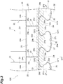
- FIG. 3 is a view of the fitting section 31 as viewed from the direction indicated by B in FIG. 2 (that is, as viewed from the upstream side in direction of the rotation axis).
- the support 32 is omitted, and the shielding member 33 is indicated by a broken line.
- a plurality of protrusions 24 and a plurality of grooves 26 are alternately formed in the circumferential direction. The grooves 26 are formed between a pair of adjacent protrusions 24.
- the protrusions 24 and the grooves 26 extend in the direction of the rotation axis between the upstream end surface 22a and the downstream end surface 22b of the disc 22.
- the protrusion 24 is a section called a dovetail post.
- the protrusion 24 has a substantially fan-like shape in which the width of the distal end portion on the outer circumferential side is larger than the width of the proximal end portion on the inner circumferential side.
- the groove 26 is a section referred to as a disc dovetail.
- the groove 26 has a substantially fan-like shape in which the width of the bottom section on the inner circumferential side is larger than the width of the opening section on the outer circumferential side.
- the groove 26 includes a bottom surface 26a expanding to the inner circumferential side, and side surfaces 26b and 26b expanding from both ends in the width direction of the bottom surface 26a to the outer circumferential side.
- the side surfaces 26b and 26b are constituted by the side surfaces of the protrusion 24 and are inclined so that the widths thereof become narrower toward the outer circumferential side.
- the protrusion 24 has a distal end surface 24a that expands to the outer circumferential side.
- the turbine blade 23 includes a blade section 25, a protrusion 27, and a platform 28.
- the blade section 25 extends in the radial direction.
- the protrusion 27 is fitted to the groove 26 of the disc 22.
- the platform 28 supports the protrusion 27 at the end portion on the inner circumferential side of the blade section 25.
- the protrusion 27 is a section called a moving blade dovetail, and has a shape corresponding to the groove 26. That is, the protrusion 27 has a substantially fan-like shape in which the width of the distal end portion on the inner circumferential side is larger than the width of the proximal end portion on the outer circumferential side (a connecting section with the platform 28).
- the distal end portion on the inner circumferential side of the protrusion 27 is disposed on the bottom section on the inner circumferential side of the groove 26.
- the proximal end portion on the outer circumferential side of the protrusion 27 is disposed in the opening section on the outer circumferential side of the groove 26.
- the protrusion 27 includes a distal end surface 27c expanding to the inner circumferential side, and side surfaces 27d and 27d expanding from both ends of the distal end surface 27c in the width direction to the outer circumferential side.
- the side surfaces 27d and 27d are inclined so that the width becomes narrower toward the outer circumferential side.
- the end surface 27a on the upstream side of the protrusion 27 is disposed to form the same plane as the end surface 22a on the upstream side of the disc 22.
- the end surface formed by the end surface 27a of the protrusion 27 and the end surface 22a of the disc 22 is referred to as an "end surface 31a on the upstream side of the fitting section 31.”
- the platform 28 includes an outer circumferential surface 28a to which the end portion on the inner circumferential side of the blade section 25 is fixed, an inner circumferential surface 28b to which the proximal end portion of the protrusion 27 is fixed, and a side surface 28c formed on both end sides in the circumferential direction.
- the inner circumferential surface 28b of the platform 28 extends in the circumferential direction to cover the distal end surface 24a of the protrusion 24 of the disc 22.
- One side surface 28c of the platform 28 of the turbine blade 23 faces the other side surface 28c of the platform 28 of the adjacent turbine blade 23.
- a seal member 29 is disposed between the side surfaces 28c facing each other.
- a support section 34 which supports the shielding member 33 is formed on an end surface on the upstream side of the platform 28, a support section 34 which supports the shielding member 33 is formed. Details of the configuration of the support section 34 will be described later together with the configuration of the shielding member 33.
- FIG. 3 illustrates a state in which a centrifugal force directed toward the outer circumferential side acts on the turbine blade 23 by the rotational driving of the disc 22.
- the side surface 27d of the protrusion 27 of the turbine blade 23 comes into contact with the side surface 26b of the groove 26 of the disc 22.
- a gap GP1 is formed between the bottom surface 26a of the groove 26 and the distal end surface 27c of the protrusion 27.
- the gap GP1 existing on the inner circumferential side of the contact section between the side surface 27d and the side surface 26b is referred to as a "gap GP1 on the inner circumferential side.” Further, a gap is formed between the distal end surface 24a of the protrusion 24 of the disc and the inner circumferential surface 28b of the platform 28.
- the gap GP 2 existing on the outer circumferential side of the contact section between the side surface 27d and the side surface 26b is referred to as a "gap GP 2 on the outer circumferential side.”
- the support 32 is an annular plate material that covers the end surface 22a on the upstream side of the disc 22.
- the support 32 is disposed at a position spaced apart from the end surface 22a on the upstream side of the disc 22 toward the upstream side.
- a support section 36 which supports the end surface 31a on the upstream side of the fitting section 31 is formed on the back surface 32a of the support 32.
- the support section 36 is an annular wall section protruding from the back surface 32a of the support 32 toward the end surface 31a on the upstream side of the fitting section 31.
- the support section 36 is formed at a position spaced apart from the outer circumferential surface 32b of the support 32 to the inner circumferential side.
- a portion on a side closer to the outer circumferential side than the support section 36 functions as a flange section 37 which prevents extraction of the shielding member 33.
- the support section 36 prevents the protrusion 27 of the turbine blade 23 from falling out of the groove 26 of the disc 22.
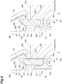
- FIG. 4 is an enlarged view illustrating the structure around the shielding member 33, in the turbine blade mounting structure 100.
- FIG. 4(a) illustrates a state in which no centrifugal force acts on the shielding member 33
- FIG. 4(b) illustrates a state in which a centrifugal force acts on the shielding member 33.
- the shielding member 33 is an annular member that covers a gap between the disc 22 and the turbine blade 23 in the fitting section 31.
- the shielding member 33 covers the gap GP2 on the outer circumferential side (in FIG. 3 , a portion covered with the shielding member 33 is illustrated by hatching).
- the shielding member 33 is disposed in the space between the end surface 31a on the upstream side of the fitting section 31 and the flange section 37 of the support 32, on the outer circumference side of the support section 36 of the support 32.
- the shielding member 33 is made of a material having high heat resistance, and is made of, for example, nickel or a composite material.
- the shielding member 33 has an upstream end surface 33a, a downstream end surface 33b, an inner circumferential surface 33c, an outer circumferential surface 33d, and a guided surface 33e.
- the end surface 33a faces the back surface 37a of the flange section 37 of the support 32.
- the end surface 33b faces the end surface 31a on the upstream side of the fitting section 31.
- the inner circumferential surface 33c faces the outer circumferential surface 36a of the support section 36 of the support 32.
- the outer circumferential surface 33d is supported by a support section 34 formed on the platform 28.
- the guided surface 33e is formed between the upstream end surface 33a and the outer circumferential surface 33d.
- the guided surface 33e is a surface formed at an end portion on the outer circumferential side of the shielding member 33.
- the guided surface 33e is a surface that comes into contact with a guiding surface 42b of the support section 34 to be described later.
- the guided surface 33e has a shape that expands to the outer circumferential side from the upstream side toward the downstream side.
- the guided surface 33e is an inclined surface which is inclined to the outer circumferential side from the upstream side toward the downstream side.
- the support section 34 is constituted by forming a groove 42 on a wall section 41 disposed at a position on the outer circumferential side of the shielding member 33.
- the wall section 41 is a part of the platform 28.
- the wall section 41 is a section that protrudes to the upstream side from the end surface 31a on the upstream side of the fitting section 31, at the position on the outer circumferential side of the fitting section 31.
- the groove 42 is formed on the inner circumferential surface 41a of the protruding wall section 41 to extend in the circumferential direction. Further, as long as the support section 34 has a structure capable of supporting the shielding member 33, the support section 34 may not be provided on the turbine blade 23 side.
- the support section 34 may be formed by adding a predetermined support mechanism or the like to the disc side.
- the groove 42 includes a receiving surface 42a which receives the end surface 33b on the downstream side of the shielding member 33, and a guiding surface 42b which guides the guided surface 33e of the shielding member 33.
- the receiving surface 42a is the same plane continued with the end surface 31a on the upstream side of the fitting section 31.
- the guiding surface 42b is a surface which comes into contact with the guided surface 33e of the shielding member 33 when centrifugal force acts on the shielding member 33.
- the guiding surface 42b has a shape that expands to the outer circumferential side from the upstream side toward the downstream side.
- the guiding surface 42b is an inclined surface which is inclined to the outer circumferential side from the upstream side toward the downstream side.
- the guiding surface 42b linearly extends from the inner circumferential surface 41a of the wall section 41 toward the bottom section on the outer circumferential side of the groove 42.
- An angle of the guiding surface 42b and the guided surface 33e with respect to direction of the rotation axis is not particularly limited, but the angle may be set to 30° to 80° in order to efficiently convert some of the centrifugal force to the pressing force toward the downstream side.
- the shielding member 33 is in a state of being prevented from falling out by being housed in the space formed by the disc 22, the support section 34, and the support 32. However, the shielding member 33 is not fixed to any member, and is in a free state in the space (a state in which movement in a space is permitted).
- the shielding member 33 is in a state of being spaced apart from the support section 34.
- a centrifugal force acts on the shielding member 33 toward the outer circumferential side. In this state, as illustrated in FIG.
- the shielding member 33 is in a state of being supported by the support section 34. Specifically, the guided surface 33e of the shielding member 33 abuts on the guiding surface 42b of the support section 34. At the same time, the end surface 33b on the downstream side of the shielding member 33 abuts on the receiving surface 42a of the support section 34 and the end surface 31a on the upstream side of the fitting section 31. Thus, the gap GP2 of the fitting section 31 is blocked by the shielding member 33.
- the inner circumferential surface 33c of the shielding member 33 is disposed at the positions of the side surfaces 26b and 27d that abut on each other as load receiving surfaces. Therefore, the entire region of the gap GP2 on the outer circumferential side of the fitting section 31 in the radial direction is blocked by the shielding member 33.
- the size of the shielding member 33 in the radial direction is not particularly limited, and for example, the inner circumferential surface 33c of the shielding member 33 may come to the gap GP2. That is, a region that is not blocked by the shielding member 33 may exist in a part of the gap GP2.
- the shielding member 33 is divided into a plurality of pieces in the circumferential direction.
- the shielding member 33 is divided into four pieces 33A, 33B, 33C, and 33D.
- the shielding member 33 may interfere with the wall section 41 of the support section 34 at the time of assembling.
- the shielding member 33 may be deformed by the influence of thermal expansion.
- the shielding member 33 is easily assembled, and it is possible to suppress the deformation due to the influence of thermal expansion.
- a centrifugal force directed toward the outer circumferential edge acts on the respective pieces 33A, 33B, 33C, and 33D, as indicated by an arrow in FIG. 5 .
- the number of divisions of the shielding member 33 is not particularly limited, and may be two or more.
- the shielding member 33 may be finely divided, and a piece may be provided for a single turbine blade 23.
- Each of the pieces 33A, 33B, 33C, and 33D of the shielding member 33 is formed with a detent 45 which prevents movement in the circumferential direction.
- the detent 45 may protrude from the end surface of the shielding member 33.
- the detent 45 may be fitted to a groove (not illustrated) formed in the support 32 to restrict the movement of the shielding member 33 in the circumferential direction.
- the detent 45 may be provided by forming a groove on the end surface of the shielding member 33.
- the detent 45 may restrict the movement of the shielding member 33 in the circumferential direction, by fitting a protrusion (not illustrated) formed on the support 32. Further, the end surface of the shielding member 33 may be cut obliquely.
- the shielding member 33 may be provided over the whole circumference of the fitting section 31, but the shielding member 33 may be provided in a partial region of the fitting section 31 in the circumferential direction. That is, in the partial region of the fitting section 31 in the circumferential direction, the flow of the cooling air CS is shield by the shielding member 33, and by not providing the shielding member 33 in the other partial region, the flow rate of the cooling air may be adjusted.
- the guided surface 33e of the shielding member 33 may be formed over the entire region of the shielding member in the circumferential direction, but the guided surface 33e may be formed only in a partial region in the circumferential direction. For example, in the circumferential direction, a region provided with the guided surface 33e and a region not provided with the guided surface 33e may be alternately formed at regular intervals. However, it is necessary to provide the guided surface 33e in at least one place of one piece of the shielding member 33.
- FIG. 6(a) is an enlarged view illustrating the flow of the cooling air CS in the turbine blade mounting structure according to the comparative example.
- the turbine blade mounting structure according to the comparative example illustrated in FIG. 6(a) does not include a shielding member. Accordingly, the cooling air CS linearly flows into the gap GP2 between the disc 22 and the turbine blade 23. Therefore, in some cases, when the excessive cooling air CS is extracted from the main stream MS of the air flow of the jet engine 1, the performance of the jet engine 1 may be degraded.
- FIG. 6(b) is an enlarged view illustrating the flow of the cooling air CS in the turbine blade mounting structure according to another comparative example.
- 6(b) includes a shielding section 50 that protrudes from the distal end surface 24a of the protrusion 24 of the disc 22 to the outer circumferential side.
- a shielding section 50 since it is not possible to sufficiently block the gap GP2, the cooling air CS linearly flows in a part of the gap GP2. Therefore, in some cases, it is not possible to sufficiently adjust the cooling air CS flowing to the disc 22 side.
- the excessive cooling air CS may flow to the disc side. In this way, when the cooling air CS excessively increases, in some cases, the flow rate of the main stream MS of the air decreases, which lead to degradation of the performance of the jet engine.
- a guiding surface 42b expanding to the outer circumferential side from the upstream side toward the downstream side is formed in the support section 34 that supports the outer circumferential end portion of the shielding member 33.
- a guided surface 33e, which expands to the outer circumferential side from the upstream side toward the downstream side and abuts on the guiding surface 42b, is formed at the end portion of the outer circumferential side of the shielding member 33. Therefore, when the centrifugal force acts on the shielding member 33 by rotationally driving the disc 22, the guided surface 33e abuts on the guiding surface 42b and is guided, and thus, a force directed toward the downstream side acts on the shielding member 33.
- the guided surface 33e of the shielding member 33 abuts on and is pressed against the guiding surface 42b of the support section 34, the guided surface 33e moves along the guiding surface 42b, and thus, the guided surface 33e moves toward the downstream side as well as the outer circumferential side.
- the whole shielding member 33 moves to the downstream side, and the end surface 33b on the downstream side of the shielding member 33 comes into contact with the end surface 31a on the upstream side of the fitting section 31 and the receiving surface 42a of the support section 34, and is pressed to the downstream side.
- some of the centrifugal force acting on the shielding member 33 is converted into a pressing force against the end surface 31a of the fitting section 31.
- the shielding member 33 is pressed against the fitting section 31 in a state of covering the gap GP2 between the disc 22 and the turbine blade 23 in the fitting section 31.
- the shielding member 33 is in a state of not being fixed to any member, and is pressed against the end surface 31a of the fitting section 31 with sufficient force at the time of rotationally driving of the disc 22. Further, such a shielding structure can be achieved with a simple structure that merely forms the guiding surface and the guided surface.
- the guiding surface 42b and the guided surface 33e are inclined surfaces which are inclined to the outer circumferential side from the upstream side toward the downstream side. Therefore, when the centrifugal force acts on the shielding member 33, the shielding member 33 is smoothly pressed against the fitting section 31 on the downstream side.
- the guided surface and the guided surface 33e may be curved surfaces 133e and 142b (see FIG. 7(a) ) which are curved and expand to protrude to the outer circumferential side, and may be curved surfaces 233e and 242b (see FIG. 7(b) ) which are curved to protrude toward the inner circumferential side.
- the shielding member 33 may be formed with a communicating section 44 that allows the space on the upstream side of the shielding member 33 to communicate with the gap GP2.
- the communicating section 44 illustrated in FIG. 7(a) is constituted by a through-hole penetrating through the shielding member 33 in the direction of the rotation axis.
- the gap GP2 communicates with the space on the upstream side of the shielding member 33 via the communicating section 44.
- the communicating section 43 illustrated in FIG. 7(b) is formed by forming slots on the end surface 33b on the downstream side of the shielding member 33.
- some of the cooling air CS can flow through the gap GP 2 via the communicating sections 44 and 43, and it is possible to more finely adjust the amount of the cooling air CS flowing to the disc 22 side.
- the fitting section of the turbine blade and the disc having a substantially fan shape is described as an example, but the shape of the fitting section is not particularly limited.
- a so-called Christmas tree type fitting section having multiple wavy shapes on both side surfaces may be adopted.
Landscapes
- Engineering & Computer Science (AREA)
- Mechanical Engineering (AREA)
- General Engineering & Computer Science (AREA)
- Chemical & Material Sciences (AREA)
- Combustion & Propulsion (AREA)
- Turbine Rotor Nozzle Sealing (AREA)
Abstract
Description
- The present disclosure relates to a turbine blade mounting structure. This application is based on Japanese Patent Application No.
2015-100018 filed on May 15, 2015 - Patent Literature 1 discloses a turbine blade mounting structure of a jet engine, in which a turbine blade is mounted on an outer circumferential edge of a disc that is rotationally driven. In the turbine blade mounting structure, a plurality of grooves is formed on the outer circumferential edge of the disc, and an end portion of an inner circumferential side of the turbine blade is fitted to each groove.
- Patent Literature 1: Japanese Unexamined Patent Publication No.
H7-26905 - Here, in some cases, the jet engine has a configuration in which some of taken air as cooling air (cooling fluid) flows to the disc to cool the disc. However, when the cooling air flows into a gap between the turbine blade and disc, there is a possibility that excessive cooling air flows to the disc side. In this way, when the cooling air increases more than necessary, in some cases, by a decrease in mainstream flow rate of air, the performance of the jet engine is degraded.
- Accordingly, the present disclosure illustrates a turbine blade mounting structure capable of adjusting the flow rate of cooling fluid flowing to the disc side.
- A turbine blade mounting structure according to an aspect of the present disclosure is a turbine blade mounting structure in which a turbine blade is mounted to an outer circumferential edge of a disc rotationally driven, the turbine blade mounting structure including: a fitting section formed by fitting an end portion on an inner circumferential side of the turbine blade to a groove extending in a direction of a rotation axis at the outer circumferential edge of the disc; a shielding member which is disposed on an end surface on an upstream side of the fitting section to shield fluid flowing to the fitting section; and a support section which supports an end portion on an outer circumferential side of the shielding member at least when the disc is rotationally driven. A guiding surface expanding to the outer circumferential side from the upstream side toward the downstream side is formed on the support section, a guided surface expanding to the outer circumferential side from the upstream side toward the downstream side is formed at an end portion on the outer circumferential side of the shielding member, and the shielding member covers a gap between the disc and the turbine blade in the fitting section in a state in which the guided surface abuts against the guiding surface at least when the disc is rotationally driven.
- According to the present disclosure, it is possible to adjust the flow rate of the cooling fluid flowing to the disc side.
-
-
FIG. 1 is a schematic cross-sectional view illustrating a schematic configuration of a jet engine equipped with a turbine blade mounting structure according to the present disclosure. -
FIG. 2 is an enlarged view of a portion denoted by A inFIG. 1 , and is an enlarged sectional view of the turbine blade mounting structure. -
FIG. 3 is a view of a fitting section as viewed from a direction indicated by B inFIG. 2 . -
FIG. 4 is an enlarged view illustrating a structure around a shielding member of the turbine blade mounting structure,FIG. 4(a) illustrates a state in which no centrifugal force acts on the shielding member, andFIG. 4(b) illustrates a state in which centrifugal force acts on the shielding member. -
FIG. 5 is a view of the shielding member as viewed from a direction of the rotation axis. -
FIGS. 6(a) and 6(b) are enlarged views illustrating the flow of cooling air in a turbine blade mounting structure according to a comparative example, andFIG. 6(c) is an enlarged view illustrating a flow of cooling air in the turbine blade mounting structure according to the present disclosure. -
FIGS. 7(a) and 7(b) are views illustrating a shielding member of a turbine blade mounting structure according to a modified example. - In the turbine blade mounting structure according to an aspect of the present disclosure, a guiding surface expanding to the outer circumferential side from an upstream side toward a downstream side is formed in a support section that supports an end portion of the outer circumferential side of the shielding member. A guided surface expanding to the outer circumferential side from the upstream side toward the downstream side is formed at the end portion of the outer circumferential side of the shielding member. Therefore, when a centrifugal force acts on the shielding member toward the outer circumferential side by rotational driving of the disc, the guided surface abuts on the guiding surface and is guided, and thus, a force directed toward the downstream side acts on the shielding member. The shielding member covers a gap between the disc and the turbine blade in the fitting section in a state in which the guided surface abuts on the guiding surface at least when the disc is rotationally driven. Thus, in a state in which the shielding member is pressed against the fitting section on the downstream side, the shielding member can cover the gap between the disc and the turbine blade in the fitting section to shield the fluid. This makes it possible to adjust the flow rate of the fluid flowing into the gap between the disc and the turbine blade. Therefore, it is possible to adjust the flow rate of the cooling fluid flowing to the disc side.
- In the turbine blade mounting structure according to an aspect of the present disclosure, the guiding surface and the guided surface may be inclined surfaces which are inclined to the outer circumferential side from the upstream side toward the downstream side. Therefore, when the centrifugal force acts on the shielding member, the shielding member is smoothly pressed against the fitting section on the downstream side.
- In the turbine blade mounting structure according to an aspect of the present disclosure, the shielding member may be formed with a communicating section that allows a space on the upstream side of the shielding member to communicate with the gap. As a result, some of the cooling fluid can be made to flow into the gap between the turbine blade and the disc, which makes it possible to finely adjust the flow rate of the cooling fluid flowing to the disc side.
- Embodiments of the present disclosure will be described in detail with reference to the drawings. In the description of the drawings, the same elements or the corresponding elements are denoted by the same reference numerals, and repeated explanations may be omitted.
-
FIG. 1 is a schematic cross-sectional view illustrating a schematic configuration of a jet engine equipped with a turbine blade mounting structure according to the present embodiment. A jet engine 1 of the present embodiment includes afan 2, acompressor 3, acombustor 4, and aturbine 5. - The
fan 2 is intended to take outside air into the jet engine 1, and has a plurality of moving blades arranged around a rotation axis L1 of ashaft section 21 to be rotationally driven. Thecompressor 3 compresses the air which was taken in by thefan 2. Thecompressor 3 has a configuration in which the rotating blades to be rotationally driven and the fixed stationary blades are alternately arranged in a plurality of stages in the flowing direction of air. Thecombustor 4 combusts the air compressed by thecompressor 3 with the fuel. Thecombustor 4 includes a fuel supply mechanism (not illustrated) and an ignition device (not illustrated). Theturbine 5 converts some of the velocity energy of the combustion gas generated by combustion of air and fuel in thecombustor 4 into rotational energy. Theturbine 5 drives thefan 2 and thecompressor 3 by the rotational energy. Theturbine 5 has adisc 22 to be rotatably driven by being connected to theshaft section 21, and a plurality ofturbine blades 23 arranged around the rotation axis LI on the outer circumferential edge of thedisc 22. - In the jet engine 1 having such a configuration, the air is taken into the jet engine 1 by the
fan 2. Further, the air supplied to thecompressor 3 is compressed by thecompressor 3 and then is combusted with the fuel in thecombustor 4. Some of the velocity energy of the combustion gas generated by combustion is converted into rotational energy by theturbine 5, and is used for driving thefan 2 and thecompressor 3. Meanwhile, the remaining velocity energy of the combustion gas is used to impart propulsive force to the jet engine 1 when the combustion gas is exhausted from the rear part of the jet engine 1. As a result, the jet engine 1 propels. The flow of the air and combustion gas is taken as main stream MS. Some of the air in thecompressor 3 passes through the flow channel on the inner circumferential side of thecombustor 4 and is used as the cooling air CS of thedisc 22 in theturbine 5. In this specification, the direction along the rotation axis L1 is referred to as a "rotation axis direction", and the terms "upstream side" and "downstream side" are used on the basis of the flow of air which is taken in the jet engine 1. That is, inFIGS. 1 ,2 ,4 ,6 and7 , the left side of the sheet corresponds to an "upstream side" and the right side of the sheet corresponds to a "downstream side." Also, the terms "outer circumference side" and "inner circumference side" are used on the basis of the rotation axis L1. - Next, a turbine
blade mounting structure 100 according to the present embodiment will be described.FIG. 2 is an enlarged view of a portion denoted by A inFIG. 1 , which is an enlarged sectional view of the turbineblade mounting structure 100.FIG. 2 is a cross-sectional view taken along a line II-II inFIG. 3 . As illustrated inFIG. 2 , the turbineblade mounting structure 100 includes afitting section 31, asupport 32, ashielding member 33, and asupport section 34. Thefitting section 31 fits theturbine blade 23 with thedisc 22. Thesupport 32 supports theturbine blade 23 at thefitting section 31. The shieldingmember 33 shields the flow of the cooling air CS to the gap between thedisc 22 and theturbine blade 23 in thefitting section 31. Thesupport section 34 supports the end portion on the outer circumferential side of the shieldingmember 33 at least when thedisc 22 is rotationally driven. - The
fitting section 31 will be described with reference toFIGS. 2 and3. FIG. 3 is a view of thefitting section 31 as viewed from the direction indicated by B inFIG. 2 (that is, as viewed from the upstream side in direction of the rotation axis). However, inFIG. 3 , in order to illustrate the gap between theturbine blade 23 and thedisc 22, thesupport 32 is omitted, and the shieldingmember 33 is indicated by a broken line. On the outer circumferential edge of thedisc 22, a plurality ofprotrusions 24 and a plurality ofgrooves 26 are alternately formed in the circumferential direction. Thegrooves 26 are formed between a pair ofadjacent protrusions 24. Theprotrusions 24 and thegrooves 26 extend in the direction of the rotation axis between theupstream end surface 22a and thedownstream end surface 22b of thedisc 22. Theprotrusion 24 is a section called a dovetail post. Theprotrusion 24 has a substantially fan-like shape in which the width of the distal end portion on the outer circumferential side is larger than the width of the proximal end portion on the inner circumferential side. Thegroove 26 is a section referred to as a disc dovetail. Thegroove 26 has a substantially fan-like shape in which the width of the bottom section on the inner circumferential side is larger than the width of the opening section on the outer circumferential side. Thegroove 26 includes abottom surface 26a expanding to the inner circumferential side, and side surfaces 26b and 26b expanding from both ends in the width direction of thebottom surface 26a to the outer circumferential side. The side surfaces 26b and 26b are constituted by the side surfaces of theprotrusion 24 and are inclined so that the widths thereof become narrower toward the outer circumferential side. Theprotrusion 24 has adistal end surface 24a that expands to the outer circumferential side. - The
turbine blade 23 includes ablade section 25, aprotrusion 27, and aplatform 28. Theblade section 25 extends in the radial direction. Theprotrusion 27 is fitted to thegroove 26 of thedisc 22. Theplatform 28 supports theprotrusion 27 at the end portion on the inner circumferential side of theblade section 25. Theprotrusion 27 is a section called a moving blade dovetail, and has a shape corresponding to thegroove 26. That is, theprotrusion 27 has a substantially fan-like shape in which the width of the distal end portion on the inner circumferential side is larger than the width of the proximal end portion on the outer circumferential side (a connecting section with the platform 28). The distal end portion on the inner circumferential side of theprotrusion 27 is disposed on the bottom section on the inner circumferential side of thegroove 26. The proximal end portion on the outer circumferential side of theprotrusion 27 is disposed in the opening section on the outer circumferential side of thegroove 26. Theprotrusion 27 includes adistal end surface 27c expanding to the inner circumferential side, andside surfaces distal end surface 27c in the width direction to the outer circumferential side. The side surfaces 27d and 27d are inclined so that the width becomes narrower toward the outer circumferential side. - The
end surface 27a on the upstream side of theprotrusion 27 is disposed to form the same plane as theend surface 22a on the upstream side of thedisc 22. The end surface formed by theend surface 27a of theprotrusion 27 and theend surface 22a of thedisc 22 is referred to as an "end surface 31a on the upstream side of thefitting section 31." - The
platform 28 includes an outercircumferential surface 28a to which the end portion on the inner circumferential side of theblade section 25 is fixed, an innercircumferential surface 28b to which the proximal end portion of theprotrusion 27 is fixed, and aside surface 28c formed on both end sides in the circumferential direction. In the present embodiment, the innercircumferential surface 28b of theplatform 28 extends in the circumferential direction to cover thedistal end surface 24a of theprotrusion 24 of thedisc 22. Oneside surface 28c of theplatform 28 of theturbine blade 23 faces theother side surface 28c of theplatform 28 of theadjacent turbine blade 23. Aseal member 29 is disposed between the side surfaces 28c facing each other. On an end surface on the upstream side of theplatform 28, asupport section 34 which supports the shieldingmember 33 is formed. Details of the configuration of thesupport section 34 will be described later together with the configuration of the shieldingmember 33. - A gap is formed between the
turbine blade 23 and thedisc 22 in thefitting section 31 having the aforementioned configuration. The gap of thefitting section 31 will be described with reference toFIG. 3. FIG. 3 illustrates a state in which a centrifugal force directed toward the outer circumferential side acts on theturbine blade 23 by the rotational driving of thedisc 22. As illustrated inFIG. 3 , theside surface 27d of theprotrusion 27 of theturbine blade 23 comes into contact with theside surface 26b of thegroove 26 of thedisc 22. In this state, a gap GP1 is formed between thebottom surface 26a of thegroove 26 and thedistal end surface 27c of theprotrusion 27. In the following description, the gap GP1 existing on the inner circumferential side of the contact section between theside surface 27d and theside surface 26b is referred to as a "gap GP1 on the inner circumferential side." Further, a gap is formed between thedistal end surface 24a of theprotrusion 24 of the disc and the innercircumferential surface 28b of theplatform 28. In the following description, thegap GP 2 existing on the outer circumferential side of the contact section between theside surface 27d and theside surface 26b is referred to as a "gap GP 2 on the outer circumferential side." - As illustrated in
FIG. 2 , thesupport 32 is an annular plate material that covers theend surface 22a on the upstream side of thedisc 22. Thesupport 32 is disposed at a position spaced apart from theend surface 22a on the upstream side of thedisc 22 toward the upstream side. Asupport section 36 which supports theend surface 31a on the upstream side of thefitting section 31 is formed on theback surface 32a of thesupport 32. Thesupport section 36 is an annular wall section protruding from theback surface 32a of thesupport 32 toward theend surface 31a on the upstream side of thefitting section 31. Thesupport section 36 is formed at a position spaced apart from the outercircumferential surface 32b of thesupport 32 to the inner circumferential side. Further, in the outer circumferential edge portion of thesupport 32, a portion on a side closer to the outer circumferential side than thesupport section 36 functions as aflange section 37 which prevents extraction of the shieldingmember 33. By pressing thefitting section 31, thesupport section 36 prevents theprotrusion 27 of theturbine blade 23 from falling out of thegroove 26 of thedisc 22. - Next, the configurations of the shielding
member 33 and thesupport section 34 will be described in detail with reference toFIG. 4. FIG. 4 is an enlarged view illustrating the structure around the shieldingmember 33, in the turbineblade mounting structure 100.FIG. 4(a) illustrates a state in which no centrifugal force acts on the shieldingmember 33, andFIG. 4(b) illustrates a state in which a centrifugal force acts on the shieldingmember 33. The shieldingmember 33 is an annular member that covers a gap between thedisc 22 and theturbine blade 23 in thefitting section 31. In the present embodiment, the shieldingmember 33 covers the gap GP2 on the outer circumferential side (inFIG. 3 , a portion covered with the shieldingmember 33 is illustrated by hatching). The shieldingmember 33 is disposed in the space between theend surface 31a on the upstream side of thefitting section 31 and theflange section 37 of thesupport 32, on the outer circumference side of thesupport section 36 of thesupport 32. The shieldingmember 33 is made of a material having high heat resistance, and is made of, for example, nickel or a composite material. - The shielding
member 33 has anupstream end surface 33a, adownstream end surface 33b, an innercircumferential surface 33c, an outercircumferential surface 33d, and a guidedsurface 33e. Theend surface 33a faces theback surface 37a of theflange section 37 of thesupport 32. Theend surface 33b faces theend surface 31a on the upstream side of thefitting section 31. The innercircumferential surface 33c faces the outercircumferential surface 36a of thesupport section 36 of thesupport 32. The outercircumferential surface 33d is supported by asupport section 34 formed on theplatform 28. The guidedsurface 33e is formed between theupstream end surface 33a and the outercircumferential surface 33d. The guidedsurface 33e is a surface formed at an end portion on the outer circumferential side of the shieldingmember 33. The guidedsurface 33e is a surface that comes into contact with a guidingsurface 42b of thesupport section 34 to be described later. The guidedsurface 33e has a shape that expands to the outer circumferential side from the upstream side toward the downstream side. In the present embodiment, the guidedsurface 33e is an inclined surface which is inclined to the outer circumferential side from the upstream side toward the downstream side. When viewing the cross section of the shielding member 33 (that is, the cross section illustrated inFIG. 4 ), the guidedsurface 33e linearly extends from theupstream end surface 33a toward the outercircumferential surface 33d on the outer circumferential side. - The
support section 34 is constituted by forming agroove 42 on awall section 41 disposed at a position on the outer circumferential side of the shieldingmember 33. Thewall section 41 is a part of theplatform 28. Thewall section 41 is a section that protrudes to the upstream side from theend surface 31a on the upstream side of thefitting section 31, at the position on the outer circumferential side of thefitting section 31. Thegroove 42 is formed on the innercircumferential surface 41a of the protrudingwall section 41 to extend in the circumferential direction. Further, as long as thesupport section 34 has a structure capable of supporting the shieldingmember 33, thesupport section 34 may not be provided on theturbine blade 23 side. Thesupport section 34 may be formed by adding a predetermined support mechanism or the like to the disc side. - The
groove 42 includes a receivingsurface 42a which receives theend surface 33b on the downstream side of the shieldingmember 33, and a guidingsurface 42b which guides the guidedsurface 33e of the shieldingmember 33. The receivingsurface 42a is the same plane continued with theend surface 31a on the upstream side of thefitting section 31. The guidingsurface 42b is a surface which comes into contact with the guidedsurface 33e of the shieldingmember 33 when centrifugal force acts on the shieldingmember 33. The guidingsurface 42b has a shape that expands to the outer circumferential side from the upstream side toward the downstream side. In the present embodiment, the guidingsurface 42b is an inclined surface which is inclined to the outer circumferential side from the upstream side toward the downstream side. When viewing the cross-section (that is, the cross-section illustrated inFIG. 4 ) of thesupport section 34, the guidingsurface 42b linearly extends from the innercircumferential surface 41a of thewall section 41 toward the bottom section on the outer circumferential side of thegroove 42. An angle of the guidingsurface 42b and the guidedsurface 33e with respect to direction of the rotation axis is not particularly limited, but the angle may be set to 30° to 80° in order to efficiently convert some of the centrifugal force to the pressing force toward the downstream side. - The shielding
member 33 is in a state of being prevented from falling out by being housed in the space formed by thedisc 22, thesupport section 34, and thesupport 32. However, the shieldingmember 33 is not fixed to any member, and is in a free state in the space (a state in which movement in a space is permitted). When thedisc 22 is not rotationally driven, no centrifugal force acts on the shieldingmember 33. Therefore, as illustrated inFIG. 4(a) , the shieldingmember 33 is in a state of being spaced apart from thesupport section 34. Meanwhile, when thedisc 22 is rotationally driven, a centrifugal force acts on the shieldingmember 33 toward the outer circumferential side. In this state, as illustrated inFIG. 4(b) , the shieldingmember 33 is in a state of being supported by thesupport section 34. Specifically, the guidedsurface 33e of the shieldingmember 33 abuts on the guidingsurface 42b of thesupport section 34. At the same time, theend surface 33b on the downstream side of the shieldingmember 33 abuts on the receivingsurface 42a of thesupport section 34 and theend surface 31a on the upstream side of thefitting section 31. Thus, the gap GP2 of thefitting section 31 is blocked by the shieldingmember 33. - In the present embodiment, as illustrated in
FIG. 3 , in a state in which the shieldingmember 33 is supported by thesupport section 34, the innercircumferential surface 33c of the shieldingmember 33 is disposed at the positions of the side surfaces 26b and 27d that abut on each other as load receiving surfaces. Therefore, the entire region of the gap GP2 on the outer circumferential side of thefitting section 31 in the radial direction is blocked by the shieldingmember 33. The size of the shieldingmember 33 in the radial direction is not particularly limited, and for example, the innercircumferential surface 33c of the shieldingmember 33 may come to the gap GP2. That is, a region that is not blocked by the shieldingmember 33 may exist in a part of the gap GP2. - Further, as illustrated in
FIG. 5 , the shieldingmember 33 is divided into a plurality of pieces in the circumferential direction. In the present embodiment, the shieldingmember 33 is divided into fourpieces member 33 is a single annular member that is not divided, the shieldingmember 33 may interfere with thewall section 41 of thesupport section 34 at the time of assembling. In addition, there is a possibility that the shieldingmember 33 may be deformed by the influence of thermal expansion. Meanwhile, by dividing the shieldingmember 33 into a plurality of pieces, the shieldingmember 33 is easily assembled, and it is possible to suppress the deformation due to the influence of thermal expansion. Further, a centrifugal force directed toward the outer circumferential edge acts on therespective pieces FIG. 5 . However, the number of divisions of the shieldingmember 33 is not particularly limited, and may be two or more. Further, the shieldingmember 33 may be finely divided, and a piece may be provided for asingle turbine blade 23. Each of thepieces member 33 is formed with adetent 45 which prevents movement in the circumferential direction. Thedetent 45 may protrude from the end surface of the shieldingmember 33. Thedetent 45, for example, may be fitted to a groove (not illustrated) formed in thesupport 32 to restrict the movement of the shieldingmember 33 in the circumferential direction. Alternatively, thedetent 45 may be provided by forming a groove on the end surface of the shieldingmember 33. Thedetent 45 may restrict the movement of the shieldingmember 33 in the circumferential direction, by fitting a protrusion (not illustrated) formed on thesupport 32. Further, the end surface of the shieldingmember 33 may be cut obliquely. - The shielding
member 33 may be provided over the whole circumference of thefitting section 31, but the shieldingmember 33 may be provided in a partial region of thefitting section 31 in the circumferential direction. That is, in the partial region of thefitting section 31 in the circumferential direction, the flow of the cooling air CS is shield by the shieldingmember 33, and by not providing the shieldingmember 33 in the other partial region, the flow rate of the cooling air may be adjusted. - The guided
surface 33e of the shieldingmember 33 may be formed over the entire region of the shielding member in the circumferential direction, but the guidedsurface 33e may be formed only in a partial region in the circumferential direction. For example, in the circumferential direction, a region provided with the guidedsurface 33e and a region not provided with the guidedsurface 33e may be alternately formed at regular intervals. However, it is necessary to provide the guidedsurface 33e in at least one place of one piece of the shieldingmember 33. - Next, the operation and effect of the turbine
blade mounting structure 100 according to the present embodiment will be described. -
FIG. 6(a) is an enlarged view illustrating the flow of the cooling air CS in the turbine blade mounting structure according to the comparative example. The turbine blade mounting structure according to the comparative example illustrated inFIG. 6(a) does not include a shielding member. Accordingly, the cooling air CS linearly flows into the gap GP2 between thedisc 22 and theturbine blade 23. Therefore, in some cases, when the excessive cooling air CS is extracted from the main stream MS of the air flow of the jet engine 1, the performance of the jet engine 1 may be degraded.FIG. 6(b) is an enlarged view illustrating the flow of the cooling air CS in the turbine blade mounting structure according to another comparative example. The turbine blade mounting structure illustrated inFIG. 6(b) includes ashielding section 50 that protrudes from thedistal end surface 24a of theprotrusion 24 of thedisc 22 to the outer circumferential side. However, in such ashielding section 50, since it is not possible to sufficiently block the gap GP2, the cooling air CS linearly flows in a part of the gap GP2. Therefore, in some cases, it is not possible to sufficiently adjust the cooling air CS flowing to thedisc 22 side. When adopting the turbine blade mounting structure according to the comparative example, there is a possibility that the excessive cooling air CS may flow to the disc side. In this way, when the cooling air CS excessively increases, in some cases, the flow rate of the main stream MS of the air decreases, which lead to degradation of the performance of the jet engine. - Meanwhile, in the turbine
blade mounting structure 100 according to the present embodiment, a guidingsurface 42b expanding to the outer circumferential side from the upstream side toward the downstream side is formed in thesupport section 34 that supports the outer circumferential end portion of the shieldingmember 33. A guidedsurface 33e, which expands to the outer circumferential side from the upstream side toward the downstream side and abuts on the guidingsurface 42b, is formed at the end portion of the outer circumferential side of the shieldingmember 33. Therefore, when the centrifugal force acts on the shieldingmember 33 by rotationally driving thedisc 22, the guidedsurface 33e abuts on the guidingsurface 42b and is guided, and thus, a force directed toward the downstream side acts on the shieldingmember 33. - For example, when the
disc 22 is rotationally driven from the state illustrated inFIG. 4(a) , a centrifugal force acts on the shieldingmember 33, and the shieldingmember 33 is pulled toward the outer circumferential side. At this time, the guidedsurface 33e of the shieldingmember 33 is brought into contact with and pressed against the guidingsurface 42b of thesupport section 34. The guidingsurface 42b and the guidedsurface 33e expand to the outer circumferential side from the upstream side toward the downstream side. Therefore, when the guidedsurface 33e of the shieldingmember 33 abuts on and is pressed against the guidingsurface 42b of thesupport section 34, the guidedsurface 33e moves along the guidingsurface 42b, and thus, the guidedsurface 33e moves toward the downstream side as well as the outer circumferential side. As a result, the whole shieldingmember 33 moves to the downstream side, and theend surface 33b on the downstream side of the shieldingmember 33 comes into contact with theend surface 31a on the upstream side of thefitting section 31 and the receivingsurface 42a of thesupport section 34, and is pressed to the downstream side. In this manner, some of the centrifugal force acting on the shieldingmember 33 is converted into a pressing force against theend surface 31a of thefitting section 31. As a result, the shieldingmember 33 is pressed against thefitting section 31 in a state of covering the gap GP2 between thedisc 22 and theturbine blade 23 in thefitting section 31. - In this state, as illustrated in
FIG. 6(c) , since the cooling air CS flowing into thedisc 22 side is shielded by the shieldingmember 33, the cooling air CS is hard to flow linearly toward the gap GP2. This makes it possible to adjust the flow rate of the cooling air CS flowing into the gap GP2 between thedisc 22 and theturbine blade 23. Therefore, it is possible to adjust the flow rate of the cooling air CS flowing to thedisc 22 side. - When the shielding member is directly fixed to the
fitting section 31, there is a possibility that a problem may occur due to a difference in thermal expansion between the members. Meanwhile, when the shielding member is fixed to theplatform 28, thesupport 32 or the like and is disposed at a position spaced apart from theend surface 31a of thefitting section 31, it is not possible to sufficiently shield the cooling air CS. The shieldingmember 33 according to the present embodiment is in a state of not being fixed to any member, and is pressed against theend surface 31a of thefitting section 31 with sufficient force at the time of rotationally driving of thedisc 22. Further, such a shielding structure can be achieved with a simple structure that merely forms the guiding surface and the guided surface. - Further, in the turbine
blade mounting structure 100 of the present embodiment, the guidingsurface 42b and the guidedsurface 33e are inclined surfaces which are inclined to the outer circumferential side from the upstream side toward the downstream side. Therefore, when the centrifugal force acts on the shieldingmember 33, the shieldingmember 33 is smoothly pressed against thefitting section 31 on the downstream side. - The present disclosure is not limited to the above-described embodiments.
- In the above-described embodiment, as the guiding
surface 42b and the guidedsurface 33e, the inclined surfaces which are inclined to the outer circumferential side from the upstream side toward the downstream side are adopted. However, as long as the guidingsurface 42b and the guidedsurface 33e have the shape that expands to the outer circumferential side from the upstream side toward the downstream side, any shape may be adopted. For example, when viewing the cross-sections of the shieldingmember 33 and the support section 34 (that is, the cross section illustrated inFIG. 7 ), the guided surface and the guiding surface may becurved surfaces FIG. 7(a) ) which are curved and expand to protrude to the outer circumferential side, and may becurved surfaces FIG. 7(b) ) which are curved to protrude toward the inner circumferential side. - Further, for example, as illustrated in
FIG. 7(a) , the shieldingmember 33 may be formed with a communicatingsection 44 that allows the space on the upstream side of the shieldingmember 33 to communicate with the gap GP2. The communicatingsection 44 illustrated inFIG. 7(a) is constituted by a through-hole penetrating through the shieldingmember 33 in the direction of the rotation axis. As a result, the gap GP2 communicates with the space on the upstream side of the shieldingmember 33 via the communicatingsection 44. Alternatively, the communicatingsection 43 illustrated inFIG. 7(b) is formed by forming slots on theend surface 33b on the downstream side of the shieldingmember 33. As a result, some of the cooling air CS can flow through thegap GP 2 via the communicatingsections disc 22 side. - Further, as a structure of the fitting section of the turbine blade and the disc, the fitting section having a substantially fan shape is described as an example, but the shape of the fitting section is not particularly limited. For example, a so-called Christmas tree type fitting section having multiple wavy shapes on both side surfaces may be adopted.
-
- 1 jet engine
- 5 turbine
- 22 disc
- 23 turbine blade
- 26 groove
- 31 fitting section
- 33 shielding member
- 33e guided surface
- 34 support section
- 42b guiding surface
Claims (3)
- A turbine blade mounting structure in which a turbine blade is mounted to an outer circumferential edge of a disc to be rotationally driven, the turbine blade mounting structure comprising:a fitting section formed by fitting an end portion on an inner circumferential side of the turbine blade to a groove extending in a direction of a rotation axis at the outer circumferential edge of the disc;a shielding member which is disposed on an end surface on an upstream side of the fitting section to shield fluid flowing to the fitting section; anda support section which supports an end portion on an outer circumferential side of the shielding member at least when the disc is rotationally driven,wherein a guiding surface expanding to the outer circumferential side from the upstream side toward the downstream side is formed on the support section,a guided surface expanding to the outer circumferential side from the upstream side toward the downstream side is formed at an end portion on the outer circumferential side of the shielding member, andthe shielding member covers a gap between the disc and the turbine blade in the fitting section in a state in which the guided surface abuts against the guiding surface at least when the disc is rotationally driven.
- The turbine blade mounting structure according to claim 1, wherein the guiding surface and the guided surface are inclined surfaces which are inclined toward the outer circumferential side from the upstream side toward the downstream side.
- The turbine blade mounting structure according to claim 1 or 2, wherein a communicating section through which a space on the upstream side of the shielding member communicates with the gap is formed in the shielding member.
Applications Claiming Priority (2)
| Application Number | Priority Date | Filing Date | Title |
|---|---|---|---|
| JP2015100018A JP6613611B2 (en) | 2015-05-15 | 2015-05-15 | Turbine blade mounting structure |
| PCT/JP2016/052156 WO2016185732A1 (en) | 2015-05-15 | 2016-01-26 | Turbine blade mounting structure |
Publications (3)
| Publication Number | Publication Date |
|---|---|
| EP3296518A1 true EP3296518A1 (en) | 2018-03-21 |
| EP3296518A4 EP3296518A4 (en) | 2019-05-01 |
| EP3296518B1 EP3296518B1 (en) | 2021-03-10 |
Family
ID=57319759
Family Applications (1)
| Application Number | Title | Priority Date | Filing Date |
|---|---|---|---|
| EP16796127.5A Active EP3296518B1 (en) | 2015-05-15 | 2016-01-26 | Turbine blade mounting structure |
Country Status (4)
| Country | Link |
|---|---|
| US (1) | US10577935B2 (en) |
| EP (1) | EP3296518B1 (en) |
| JP (1) | JP6613611B2 (en) |
| WO (1) | WO2016185732A1 (en) |
Families Citing this family (1)
| Publication number | Priority date | Publication date | Assignee | Title |
|---|---|---|---|---|
| CN109923699B (en) | 2016-11-07 | 2022-03-15 | 日产自动车株式会社 | Negative electrode for lithium ion battery and lithium ion battery |
Family Cites Families (24)
| Publication number | Priority date | Publication date | Assignee | Title |
|---|---|---|---|---|
| US3501249A (en) * | 1968-06-24 | 1970-03-17 | Westinghouse Electric Corp | Side plates for turbine blades |
| US3572966A (en) * | 1969-01-17 | 1971-03-30 | Westinghouse Electric Corp | Seal plates for root cooled turbine rotor blades |
| DE2139146A1 (en) | 1971-08-05 | 1973-02-15 | Metallgesellschaft Ag | PROCESS FOR THE RECOVERY OF THE SELECTIVE SOLVENT FROM THE REFINEMENT OF AN EXTRACTIVE DISTILLATION |
| JPS61205302A (en) * | 1985-03-06 | 1986-09-11 | Mitsubishi Heavy Ind Ltd | Blade stopper in axial direction for turbine moving blade |
| JP3218584B2 (en) | 1993-07-12 | 2001-10-15 | 石川島播磨重工業株式会社 | Jet engine blade holding structure |
| JP2726895B2 (en) | 1994-09-14 | 1998-03-11 | 川崎重工業株式会社 | Mounting structure of ceramic blade |
| JPH08296455A (en) | 1995-04-27 | 1996-11-12 | Ishikawajima Harima Heavy Ind Co Ltd | Turbo engine |
| JPH11247616A (en) | 1998-03-04 | 1999-09-14 | Hitachi Ltd | Gas turbine engine |
| US6176677B1 (en) | 1999-05-19 | 2001-01-23 | Pratt & Whitney Canada Corp. | Device for controlling air flow in a turbine blade |
| US7147440B2 (en) * | 2003-10-31 | 2006-12-12 | General Electric Company | Methods and apparatus for cooling gas turbine engine rotor assemblies |
| US7264448B2 (en) * | 2004-10-06 | 2007-09-04 | Siemens Power Corporation, Inc. | Remotely accessible locking system for turbine blades |
| US8425194B2 (en) | 2007-07-19 | 2013-04-23 | General Electric Company | Clamped plate seal |
| JP5120014B2 (en) | 2008-03-28 | 2013-01-16 | 株式会社Ihi | Wing rotation device |
| EP2146055B2 (en) * | 2008-07-17 | 2022-01-19 | Ansaldo Energia S.P.A. | Sealing element for a gas turbine, a gas turbine including said sealing element and method for cooling said sealing element |
| EP2184443A1 (en) | 2008-11-05 | 2010-05-12 | Siemens Aktiengesellschaft | Gas turbine with locking plate between blade foot and disk |
| US8696320B2 (en) * | 2009-03-12 | 2014-04-15 | General Electric Company | Gas turbine having seal assembly with coverplate and seal |
| EP2239419A1 (en) * | 2009-03-31 | 2010-10-13 | Siemens Aktiengesellschaft | Axial turbo engine rotor with sealing disc |
| US8602737B2 (en) | 2010-06-25 | 2013-12-10 | General Electric Company | Sealing device |
| FR2973433A1 (en) | 2011-04-04 | 2012-10-05 | Snecma | Turbine rotor for low pressure turbomachine e.g. turbojet of aircraft, has upstream and downstream disks arranged coaxially, and bearing unit supporting end portion of flange to prevent deviation of flange of downstream disk |
| US8740573B2 (en) * | 2011-04-26 | 2014-06-03 | General Electric Company | Adaptor assembly for coupling turbine blades to rotor disks |
| US20130202433A1 (en) | 2012-02-07 | 2013-08-08 | General Electric Company | Seal assembly for turbine coolant passageways |
| US9803485B2 (en) * | 2013-03-05 | 2017-10-31 | Rolls-Royce North American Technologies, Inc. | Turbine segmented cover plate retention method |
| JP5358031B1 (en) * | 2013-03-22 | 2013-12-04 | 三菱重工業株式会社 | Turbine rotor, turbine, and seal plate removal method |
| FR3011032B1 (en) * | 2013-09-25 | 2017-12-29 | Snecma | ROTARY ASSEMBLY FOR TURBOMACHINE |
-
2015
- 2015-05-15 JP JP2015100018A patent/JP6613611B2/en active Active
-
2016
- 2016-01-26 EP EP16796127.5A patent/EP3296518B1/en active Active
- 2016-01-26 WO PCT/JP2016/052156 patent/WO2016185732A1/en not_active Ceased
- 2016-01-26 US US15/572,396 patent/US10577935B2/en active Active
Also Published As
| Publication number | Publication date |
|---|---|
| US20180112532A1 (en) | 2018-04-26 |
| US10577935B2 (en) | 2020-03-03 |
| EP3296518B1 (en) | 2021-03-10 |
| EP3296518A4 (en) | 2019-05-01 |
| WO2016185732A1 (en) | 2016-11-24 |
| JP2016217173A (en) | 2016-12-22 |
| JP6613611B2 (en) | 2019-12-04 |
Similar Documents
| Publication | Publication Date | Title |
|---|---|---|
| CN104736799B (en) | Turbine Nozzle Fixed Portion Structure and Turbine Using the Fixed Portion Structure | |
| CN104508251B (en) | Cover assembly and sealing member for gas-turbine unit | |
| EP2527596B1 (en) | Turbine rotor blade and turbo machine | |
| CN103459778B (en) | Gas turbine comprising a heat shield and method of operation | |
| US10794224B2 (en) | Gas turbine and method of attaching a turbine nozzle guide vane segment of a gas turbine | |
| US9605551B2 (en) | Axial seal in a casing structure for a fluid flow machine | |
| JP2017133518A (en) | Gas turbine rotor blade, gas turbine rotor, and method of assembling rotor assembly | |
| EP2415970A2 (en) | A seal assembly | |
| JP2015526650A (en) | Turbine rotor for turbomachine | |
| EP3553276B1 (en) | Gas turbine engine rotor with coolant flow redirection component | |
| US8714908B2 (en) | Shroud leakage cover | |
| EP2649279B1 (en) | Fluid flow machine especially gas turbine penetrated axially by a hot gas stream | |
| US20120134779A1 (en) | Gas turbine of the axial flow type | |
| EP3058181B1 (en) | Seal assembly for a gap between outlet portions of adjacent transition ducts in a gas turbine engine | |
| EP3296518B1 (en) | Turbine blade mounting structure | |
| EP2821622B1 (en) | Gas turbine engine | |
| EP2692993A1 (en) | Gas turbine | |
| US20090033036A1 (en) | Gas turbine with annular heat shield | |
| US20140037438A1 (en) | Turbine shroud for a turbomachine | |
| JP2005194914A (en) | Seal structure and turbine nozzle | |
| US20180023404A1 (en) | Ring segment system for gas turbine engines |
Legal Events
| Date | Code | Title | Description |
|---|---|---|---|
| STAA | Information on the status of an ep patent application or granted ep patent |
Free format text: STATUS: THE INTERNATIONAL PUBLICATION HAS BEEN MADE |
|
| PUAI | Public reference made under article 153(3) epc to a published international application that has entered the european phase |
Free format text: ORIGINAL CODE: 0009012 |
|
| STAA | Information on the status of an ep patent application or granted ep patent |
Free format text: STATUS: REQUEST FOR EXAMINATION WAS MADE |
|
| 17P | Request for examination filed |
Effective date: 20171215 |
|
| AK | Designated contracting states |
Kind code of ref document: A1 Designated state(s): AL AT BE BG CH CY CZ DE DK EE ES FI FR GB GR HR HU IE IS IT LI LT LU LV MC MK MT NL NO PL PT RO RS SE SI SK SM TR |
|
| AX | Request for extension of the european patent |
Extension state: BA ME |
|
| DAV | Request for validation of the european patent (deleted) | ||
| DAX | Request for extension of the european patent (deleted) | ||
| A4 | Supplementary search report drawn up and despatched |
Effective date: 20190329 |
|
| RIC1 | Information provided on ipc code assigned before grant |
Ipc: F01D 5/14 20060101ALI20190325BHEP Ipc: F02C 7/18 20060101ALI20190325BHEP Ipc: F01D 11/00 20060101AFI20190325BHEP Ipc: F02C 7/28 20060101ALI20190325BHEP Ipc: F01D 25/00 20060101ALI20190325BHEP Ipc: F01D 5/30 20060101ALI20190325BHEP |
|
| STAA | Information on the status of an ep patent application or granted ep patent |
Free format text: STATUS: EXAMINATION IS IN PROGRESS |
|
| 17Q | First examination report despatched |
Effective date: 20200304 |
|
| GRAP | Despatch of communication of intention to grant a patent |
Free format text: ORIGINAL CODE: EPIDOSNIGR1 |
|
| STAA | Information on the status of an ep patent application or granted ep patent |
Free format text: STATUS: GRANT OF PATENT IS INTENDED |
|
| INTG | Intention to grant announced |
Effective date: 20201028 |
|
| GRAS | Grant fee paid |
Free format text: ORIGINAL CODE: EPIDOSNIGR3 |
|
| GRAA | (expected) grant |
Free format text: ORIGINAL CODE: 0009210 |
|
| STAA | Information on the status of an ep patent application or granted ep patent |
Free format text: STATUS: THE PATENT HAS BEEN GRANTED |
|
| AK | Designated contracting states |
Kind code of ref document: B1 Designated state(s): AL AT BE BG CH CY CZ DE DK EE ES FI FR GB GR HR HU IE IS IT LI LT LU LV MC MK MT NL NO PL PT RO RS SE SI SK SM TR |
|
| REG | Reference to a national code |
Ref country code: GB Ref legal event code: FG4D |
|
| REG | Reference to a national code |
Ref country code: AT Ref legal event code: REF Ref document number: 1370013 Country of ref document: AT Kind code of ref document: T Effective date: 20210315 Ref country code: CH Ref legal event code: EP |
|
| REG | Reference to a national code |
Ref country code: DE Ref legal event code: R096 Ref document number: 602016054087 Country of ref document: DE |
|
| REG | Reference to a national code |
Ref country code: IE Ref legal event code: FG4D |
|
| REG | Reference to a national code |
Ref country code: LT Ref legal event code: MG9D |
|
| PG25 | Lapsed in a contracting state [announced via postgrant information from national office to epo] |
Ref country code: NO Free format text: LAPSE BECAUSE OF FAILURE TO SUBMIT A TRANSLATION OF THE DESCRIPTION OR TO PAY THE FEE WITHIN THE PRESCRIBED TIME-LIMIT Effective date: 20210610 Ref country code: HR Free format text: LAPSE BECAUSE OF FAILURE TO SUBMIT A TRANSLATION OF THE DESCRIPTION OR TO PAY THE FEE WITHIN THE PRESCRIBED TIME-LIMIT Effective date: 20210310 Ref country code: GR Free format text: LAPSE BECAUSE OF FAILURE TO SUBMIT A TRANSLATION OF THE DESCRIPTION OR TO PAY THE FEE WITHIN THE PRESCRIBED TIME-LIMIT Effective date: 20210611 Ref country code: FI Free format text: LAPSE BECAUSE OF FAILURE TO SUBMIT A TRANSLATION OF THE DESCRIPTION OR TO PAY THE FEE WITHIN THE PRESCRIBED TIME-LIMIT Effective date: 20210310 Ref country code: LT Free format text: LAPSE BECAUSE OF FAILURE TO SUBMIT A TRANSLATION OF THE DESCRIPTION OR TO PAY THE FEE WITHIN THE PRESCRIBED TIME-LIMIT Effective date: 20210310 Ref country code: BG Free format text: LAPSE BECAUSE OF FAILURE TO SUBMIT A TRANSLATION OF THE DESCRIPTION OR TO PAY THE FEE WITHIN THE PRESCRIBED TIME-LIMIT Effective date: 20210610 |
|
| REG | Reference to a national code |
Ref country code: AT Ref legal event code: MK05 Ref document number: 1370013 Country of ref document: AT Kind code of ref document: T Effective date: 20210310 |
|
| REG | Reference to a national code |
Ref country code: NL Ref legal event code: MP Effective date: 20210310 |
|
| PG25 | Lapsed in a contracting state [announced via postgrant information from national office to epo] |
Ref country code: LV Free format text: LAPSE BECAUSE OF FAILURE TO SUBMIT A TRANSLATION OF THE DESCRIPTION OR TO PAY THE FEE WITHIN THE PRESCRIBED TIME-LIMIT Effective date: 20210310 Ref country code: RS Free format text: LAPSE BECAUSE OF FAILURE TO SUBMIT A TRANSLATION OF THE DESCRIPTION OR TO PAY THE FEE WITHIN THE PRESCRIBED TIME-LIMIT Effective date: 20210310 Ref country code: SE Free format text: LAPSE BECAUSE OF FAILURE TO SUBMIT A TRANSLATION OF THE DESCRIPTION OR TO PAY THE FEE WITHIN THE PRESCRIBED TIME-LIMIT Effective date: 20210310 |
|
| PG25 | Lapsed in a contracting state [announced via postgrant information from national office to epo] |
Ref country code: NL Free format text: LAPSE BECAUSE OF FAILURE TO SUBMIT A TRANSLATION OF THE DESCRIPTION OR TO PAY THE FEE WITHIN THE PRESCRIBED TIME-LIMIT Effective date: 20210310 |
|
| PG25 | Lapsed in a contracting state [announced via postgrant information from national office to epo] |
Ref country code: CZ Free format text: LAPSE BECAUSE OF FAILURE TO SUBMIT A TRANSLATION OF THE DESCRIPTION OR TO PAY THE FEE WITHIN THE PRESCRIBED TIME-LIMIT Effective date: 20210310 Ref country code: EE Free format text: LAPSE BECAUSE OF FAILURE TO SUBMIT A TRANSLATION OF THE DESCRIPTION OR TO PAY THE FEE WITHIN THE PRESCRIBED TIME-LIMIT Effective date: 20210310 Ref country code: AT Free format text: LAPSE BECAUSE OF FAILURE TO SUBMIT A TRANSLATION OF THE DESCRIPTION OR TO PAY THE FEE WITHIN THE PRESCRIBED TIME-LIMIT Effective date: 20210310 Ref country code: SM Free format text: LAPSE BECAUSE OF FAILURE TO SUBMIT A TRANSLATION OF THE DESCRIPTION OR TO PAY THE FEE WITHIN THE PRESCRIBED TIME-LIMIT Effective date: 20210310 |
|
| PG25 | Lapsed in a contracting state [announced via postgrant information from national office to epo] |
Ref country code: IS Free format text: LAPSE BECAUSE OF FAILURE TO SUBMIT A TRANSLATION OF THE DESCRIPTION OR TO PAY THE FEE WITHIN THE PRESCRIBED TIME-LIMIT Effective date: 20210710 Ref country code: RO Free format text: LAPSE BECAUSE OF FAILURE TO SUBMIT A TRANSLATION OF THE DESCRIPTION OR TO PAY THE FEE WITHIN THE PRESCRIBED TIME-LIMIT Effective date: 20210310 Ref country code: SK Free format text: LAPSE BECAUSE OF FAILURE TO SUBMIT A TRANSLATION OF THE DESCRIPTION OR TO PAY THE FEE WITHIN THE PRESCRIBED TIME-LIMIT Effective date: 20210310 Ref country code: PL Free format text: LAPSE BECAUSE OF FAILURE TO SUBMIT A TRANSLATION OF THE DESCRIPTION OR TO PAY THE FEE WITHIN THE PRESCRIBED TIME-LIMIT Effective date: 20210310 Ref country code: PT Free format text: LAPSE BECAUSE OF FAILURE TO SUBMIT A TRANSLATION OF THE DESCRIPTION OR TO PAY THE FEE WITHIN THE PRESCRIBED TIME-LIMIT Effective date: 20210712 |
|
| REG | Reference to a national code |
Ref country code: DE Ref legal event code: R097 Ref document number: 602016054087 Country of ref document: DE |
|
| PLBE | No opposition filed within time limit |
Free format text: ORIGINAL CODE: 0009261 |
|
| STAA | Information on the status of an ep patent application or granted ep patent |
Free format text: STATUS: NO OPPOSITION FILED WITHIN TIME LIMIT |
|
| PG25 | Lapsed in a contracting state [announced via postgrant information from national office to epo] |
Ref country code: AL Free format text: LAPSE BECAUSE OF FAILURE TO SUBMIT A TRANSLATION OF THE DESCRIPTION OR TO PAY THE FEE WITHIN THE PRESCRIBED TIME-LIMIT Effective date: 20210310 Ref country code: ES Free format text: LAPSE BECAUSE OF FAILURE TO SUBMIT A TRANSLATION OF THE DESCRIPTION OR TO PAY THE FEE WITHIN THE PRESCRIBED TIME-LIMIT Effective date: 20210310 Ref country code: DK Free format text: LAPSE BECAUSE OF FAILURE TO SUBMIT A TRANSLATION OF THE DESCRIPTION OR TO PAY THE FEE WITHIN THE PRESCRIBED TIME-LIMIT Effective date: 20210310 |
|
| 26N | No opposition filed |
Effective date: 20211213 |
|
| PG25 | Lapsed in a contracting state [announced via postgrant information from national office to epo] |
Ref country code: SI Free format text: LAPSE BECAUSE OF FAILURE TO SUBMIT A TRANSLATION OF THE DESCRIPTION OR TO PAY THE FEE WITHIN THE PRESCRIBED TIME-LIMIT Effective date: 20210310 |
|
| PG25 | Lapsed in a contracting state [announced via postgrant information from national office to epo] |
Ref country code: IT Free format text: LAPSE BECAUSE OF FAILURE TO SUBMIT A TRANSLATION OF THE DESCRIPTION OR TO PAY THE FEE WITHIN THE PRESCRIBED TIME-LIMIT Effective date: 20210310 |
|
| PG25 | Lapsed in a contracting state [announced via postgrant information from national office to epo] |
Ref country code: IS Free format text: LAPSE BECAUSE OF FAILURE TO SUBMIT A TRANSLATION OF THE DESCRIPTION OR TO PAY THE FEE WITHIN THE PRESCRIBED TIME-LIMIT Effective date: 20210710 |
|
| PG25 | Lapsed in a contracting state [announced via postgrant information from national office to epo] |
Ref country code: MC Free format text: LAPSE BECAUSE OF FAILURE TO SUBMIT A TRANSLATION OF THE DESCRIPTION OR TO PAY THE FEE WITHIN THE PRESCRIBED TIME-LIMIT Effective date: 20210310 |
|
| REG | Reference to a national code |
Ref country code: CH Ref legal event code: PL |
|
| REG | Reference to a national code |
Ref country code: BE Ref legal event code: MM Effective date: 20220131 |
|
| PG25 | Lapsed in a contracting state [announced via postgrant information from national office to epo] |
Ref country code: LU Free format text: LAPSE BECAUSE OF NON-PAYMENT OF DUE FEES Effective date: 20220126 |
|
| PG25 | Lapsed in a contracting state [announced via postgrant information from national office to epo] |
Ref country code: BE Free format text: LAPSE BECAUSE OF NON-PAYMENT OF DUE FEES Effective date: 20220131 |
|
| PG25 | Lapsed in a contracting state [announced via postgrant information from national office to epo] |
Ref country code: LI Free format text: LAPSE BECAUSE OF NON-PAYMENT OF DUE FEES Effective date: 20220131 Ref country code: CH Free format text: LAPSE BECAUSE OF NON-PAYMENT OF DUE FEES Effective date: 20220131 |
|
| PG25 | Lapsed in a contracting state [announced via postgrant information from national office to epo] |
Ref country code: IE Free format text: LAPSE BECAUSE OF NON-PAYMENT OF DUE FEES Effective date: 20220126 |
|
| PG25 | Lapsed in a contracting state [announced via postgrant information from national office to epo] |
Ref country code: HU Free format text: LAPSE BECAUSE OF FAILURE TO SUBMIT A TRANSLATION OF THE DESCRIPTION OR TO PAY THE FEE WITHIN THE PRESCRIBED TIME-LIMIT; INVALID AB INITIO Effective date: 20160126 |
|
| PG25 | Lapsed in a contracting state [announced via postgrant information from national office to epo] |
Ref country code: MK Free format text: LAPSE BECAUSE OF FAILURE TO SUBMIT A TRANSLATION OF THE DESCRIPTION OR TO PAY THE FEE WITHIN THE PRESCRIBED TIME-LIMIT Effective date: 20210310 Ref country code: CY Free format text: LAPSE BECAUSE OF FAILURE TO SUBMIT A TRANSLATION OF THE DESCRIPTION OR TO PAY THE FEE WITHIN THE PRESCRIBED TIME-LIMIT Effective date: 20210310 |
|
| PG25 | Lapsed in a contracting state [announced via postgrant information from national office to epo] |
Ref country code: TR Free format text: LAPSE BECAUSE OF FAILURE TO SUBMIT A TRANSLATION OF THE DESCRIPTION OR TO PAY THE FEE WITHIN THE PRESCRIBED TIME-LIMIT Effective date: 20210310 |
|
| PG25 | Lapsed in a contracting state [announced via postgrant information from national office to epo] |
Ref country code: MT Free format text: LAPSE BECAUSE OF FAILURE TO SUBMIT A TRANSLATION OF THE DESCRIPTION OR TO PAY THE FEE WITHIN THE PRESCRIBED TIME-LIMIT Effective date: 20210310 |
|
| PGFP | Annual fee paid to national office [announced via postgrant information from national office to epo] |
Ref country code: GB Payment date: 20251220 Year of fee payment: 11 |
|
| PGFP | Annual fee paid to national office [announced via postgrant information from national office to epo] |
Ref country code: FR Payment date: 20251217 Year of fee payment: 11 |
|
| PGFP | Annual fee paid to national office [announced via postgrant information from national office to epo] |
Ref country code: DE Payment date: 20251217 Year of fee payment: 11 |