EP3296250A1 - Forklift - Google Patents
Forklift Download PDFInfo
- Publication number
- EP3296250A1 EP3296250A1 EP16792458.8A EP16792458A EP3296250A1 EP 3296250 A1 EP3296250 A1 EP 3296250A1 EP 16792458 A EP16792458 A EP 16792458A EP 3296250 A1 EP3296250 A1 EP 3296250A1
- Authority
- EP
- European Patent Office
- Prior art keywords
- pallet
- fork
- laser sensor
- laser light
- forklift
- Prior art date
- Legal status (The legal status is an assumption and is not a legal conclusion. Google has not performed a legal analysis and makes no representation as to the accuracy of the status listed.)
- Granted
Links
Images



Classifications
-
- B—PERFORMING OPERATIONS; TRANSPORTING
- B66—HOISTING; LIFTING; HAULING
- B66F—HOISTING, LIFTING, HAULING OR PUSHING, NOT OTHERWISE PROVIDED FOR, e.g. DEVICES WHICH APPLY A LIFTING OR PUSHING FORCE DIRECTLY TO THE SURFACE OF A LOAD
- B66F9/00—Devices for lifting or lowering bulky or heavy goods for loading or unloading purposes
- B66F9/06—Devices for lifting or lowering bulky or heavy goods for loading or unloading purposes movable, with their loads, on wheels or the like, e.g. fork-lift trucks
- B66F9/075—Constructional features or details
- B66F9/12—Platforms; Forks; Other load supporting or gripping members
- B66F9/16—Platforms; Forks; Other load supporting or gripping members inclinable relative to mast
-
- B—PERFORMING OPERATIONS; TRANSPORTING
- B66—HOISTING; LIFTING; HAULING
- B66F—HOISTING, LIFTING, HAULING OR PUSHING, NOT OTHERWISE PROVIDED FOR, e.g. DEVICES WHICH APPLY A LIFTING OR PUSHING FORCE DIRECTLY TO THE SURFACE OF A LOAD
- B66F9/00—Devices for lifting or lowering bulky or heavy goods for loading or unloading purposes
- B66F9/06—Devices for lifting or lowering bulky or heavy goods for loading or unloading purposes movable, with their loads, on wheels or the like, e.g. fork-lift trucks
- B66F9/063—Automatically guided
-
- B—PERFORMING OPERATIONS; TRANSPORTING
- B66—HOISTING; LIFTING; HAULING
- B66F—HOISTING, LIFTING, HAULING OR PUSHING, NOT OTHERWISE PROVIDED FOR, e.g. DEVICES WHICH APPLY A LIFTING OR PUSHING FORCE DIRECTLY TO THE SURFACE OF A LOAD
- B66F9/00—Devices for lifting or lowering bulky or heavy goods for loading or unloading purposes
- B66F9/06—Devices for lifting or lowering bulky or heavy goods for loading or unloading purposes movable, with their loads, on wheels or the like, e.g. fork-lift trucks
- B66F9/075—Constructional features or details
- B66F9/0755—Position control; Position detectors
-
- B—PERFORMING OPERATIONS; TRANSPORTING
- B66—HOISTING; LIFTING; HAULING
- B66F—HOISTING, LIFTING, HAULING OR PUSHING, NOT OTHERWISE PROVIDED FOR, e.g. DEVICES WHICH APPLY A LIFTING OR PUSHING FORCE DIRECTLY TO THE SURFACE OF A LOAD
- B66F9/00—Devices for lifting or lowering bulky or heavy goods for loading or unloading purposes
- B66F9/06—Devices for lifting or lowering bulky or heavy goods for loading or unloading purposes movable, with their loads, on wheels or the like, e.g. fork-lift trucks
- B66F9/075—Constructional features or details
- B66F9/20—Means for actuating or controlling masts, platforms, or forks
- B66F9/24—Electrical devices or systems
-
- G—PHYSICS
- G01—MEASURING; TESTING
- G01B—MEASURING LENGTH, THICKNESS OR SIMILAR LINEAR DIMENSIONS; MEASURING ANGLES; MEASURING AREAS; MEASURING IRREGULARITIES OF SURFACES OR CONTOURS
- G01B11/00—Measuring arrangements characterised by the use of optical techniques
- G01B11/002—Measuring arrangements characterised by the use of optical techniques for measuring two or more coordinates
-
- G—PHYSICS
- G01—MEASURING; TESTING
- G01B—MEASURING LENGTH, THICKNESS OR SIMILAR LINEAR DIMENSIONS; MEASURING ANGLES; MEASURING AREAS; MEASURING IRREGULARITIES OF SURFACES OR CONTOURS
- G01B11/00—Measuring arrangements characterised by the use of optical techniques
- G01B11/02—Measuring arrangements characterised by the use of optical techniques for measuring length, width or thickness
-
- G—PHYSICS
- G01—MEASURING; TESTING
- G01S—RADIO DIRECTION-FINDING; RADIO NAVIGATION; DETERMINING DISTANCE OR VELOCITY BY USE OF RADIO WAVES; LOCATING OR PRESENCE-DETECTING BY USE OF THE REFLECTION OR RERADIATION OF RADIO WAVES; ANALOGOUS ARRANGEMENTS USING OTHER WAVES
- G01S17/00—Systems using the reflection or reradiation of electromagnetic waves other than radio waves, e.g. lidar systems
- G01S17/02—Systems using the reflection of electromagnetic waves other than radio waves
- G01S17/06—Systems determining position data of a target
-
- G—PHYSICS
- G05—CONTROLLING; REGULATING
- G05D—SYSTEMS FOR CONTROLLING OR REGULATING NON-ELECTRIC VARIABLES
- G05D1/00—Control of position, course, altitude or attitude of land, water, air or space vehicles, e.g. using automatic pilots
- G05D1/02—Control of position or course in two dimensions
-
- G—PHYSICS
- G05—CONTROLLING; REGULATING
- G05D—SYSTEMS FOR CONTROLLING OR REGULATING NON-ELECTRIC VARIABLES
- G05D1/00—Control of position, course, altitude or attitude of land, water, air or space vehicles, e.g. using automatic pilots
- G05D1/02—Control of position or course in two dimensions
- G05D1/021—Control of position or course in two dimensions specially adapted to land vehicles
- G05D1/0212—Control of position or course in two dimensions specially adapted to land vehicles with means for defining a desired trajectory
- G05D1/0225—Control of position or course in two dimensions specially adapted to land vehicles with means for defining a desired trajectory involving docking at a fixed facility, e.g. base station or loading bay
-
- G—PHYSICS
- G05—CONTROLLING; REGULATING
- G05D—SYSTEMS FOR CONTROLLING OR REGULATING NON-ELECTRIC VARIABLES
- G05D1/00—Control of position, course, altitude or attitude of land, water, air or space vehicles, e.g. using automatic pilots
- G05D1/02—Control of position or course in two dimensions
- G05D1/021—Control of position or course in two dimensions specially adapted to land vehicles
- G05D1/0231—Control of position or course in two dimensions specially adapted to land vehicles using optical position detecting means
- G05D1/0238—Control of position or course in two dimensions specially adapted to land vehicles using optical position detecting means using obstacle or wall sensors
- G05D1/024—Control of position or course in two dimensions specially adapted to land vehicles using optical position detecting means using obstacle or wall sensors in combination with a laser
Definitions
- a reflective optical sensor detects upper and lower ends of an opening of a pallet. Then, a clearance between an upper surface of a fork and the upper end of the opening of the pallet and a clearance between a lower surface of the fork and the lower end of the opening of the pallet are calculated, and a fork position is adjusted so that these clearances take appropriate values.
- the present description discloses a forklift that enables detection of a lateral positional displacement and a displacement related to rotation of a pallet using a simple configuration.
- a forklift disclosed herein may comprise: a fork; a moving mechanism configured to move the fork in a first direction; a laser sensor mounted on the fork, configured to scan laser light in a second direction intersecting the first direction, and measure a distance from the laser sensor to a surrounding object based on reflected light of the scanned laser light; and a processor configured to generate a three-dimensional range image within an emission range to which the laser light is emitted based on distance data acquired when the laser sensor scans the laser light in the second direction while the moving mechanism moves the fork in the first direction.
- the laser sensor is mounted on the fork, and thus, when the fork moves in the first direction, the laser sensor moves in the first direction together therewith. Due to this, even if the laser sensor is of a one-dimensional scan type that scans the laser light in the second direction, the laser sensor can scan the laser light in the first and second directions by the motion of the fork in the first direction. Due to this, a three-dimensional range image can be acquired by using the laser sensor.
- This forklift is capable of acquiring the three-dimensional range image, so a positional displacement in a lateral direction and a displacement related to rotation of the pallet can be detected.
- a moving mechanism may comprise at least a lifting mechanism configured to move a fork up and down in a vertical direction, and a laser sensor may move up and down in the vertical direction as the fork moves up and down in the vertical direction.
- the lifting mechanism that moves the fork up and down in the vertical direction can be used to vertically scan light emitted from the laser sensor.
- the moving mechanism may comprise at least a tilting mechanism configured to tilt a distal end of the fork with respect to a proximal end of the fork, and the laser light emitted from the laser sensor may be scanned in the vertical direction as the distal end of the fork tilts with respect to the proximal end of the fork.
- the tilting mechanism that tilts the fork can be used to vertically scan the light emitted from the laser sensor.
- a processor may be configured to identify a position, an orientation, and a width of a pallet based on the three-dimensional range image. According to such a configuration, the three-dimensional position, orientation, and width of the pallet are identified based on the three-dimensional range image generated from the distance data acquired by the laser sensor, so a positional displacement in a lateral direction and a displacement related to rotation of the pallet can accurately be detected.
- the processor may be configured to selectively extract only distance data acquired from a front face of the pallet from the three-dimensional range image and identify the position, the orientation, and the width of the pallet based on a plane at the front face of the pallet identified based on the extracted distance data.
- the three-dimensional position, orientation, and width of the pallet are identified based on the distance data acquired from the front face of the pallet that was extracted from the three-dimensional range image generated from the distance data acquired by the laser sensor. Since positional information of the pallet is identified from the distance data acquired from the front face of the pallet, the positional displacement in the lateral direction and the displacement related to rotation of the pallet can accurately be detected.
- the forklift 10 is an unmanned forklift, and includes a vehicle body 12, a mast 24, a fork 22, a lift chain 26, a laser sensor 20, and a controller 30.
- the vehicle body 12 is provided with a front wheel 28 and a rear wheel 29 at each of its lateral surfaces.
- the front wheels 28 and the rear wheels 29 are supported rotatably on the vehicle body 12.
- One of the rear wheels 29 is connected to a driving motor that is not shown, and is configured to be driven to rotate by the driving motor.
- the rear wheel 29 connected to the driving motor is also connected to a steering device that is not shown, and an orientation of the wheel is adjusted by the steering device.
- the other of the rear wheels 29 is a caster wheel, and is rotated and steered by following motions of the vehicle body 12.
- the controller 30 controls the driving motor and the steering device to allow the vehicle body 12 to run on a road and to change a moving direction of the vehicle body 12.
- the mast 24 is a post mounted to a front surface of the vehicle body 12, and its axis extends in a vertical direction.
- the fork 22 is mounted to the mast 24 by being able to move in the vertical direction. Further, the fork 22 is configured capable of swinging with respect to the mast 24 by a tilting mechanism that is not shown.
- the fork 22 includes a pair of tines 22a, 22b. The tines 22a, 22b are disposed at positions spaced apart from each other in a right-and-left direction of the vehicle body 12, and extend forward of the vehicle body 12 from a mast 24 side.
- the lift chain 26 is disposed on the mast 24, and is engaged with the fork 22.
- the fork 22 When the lift chain 26 is driven by a fork lifting device 40 (shown in FIG 3 ), the fork 22 is lifted and lowered according to a motion of the lift chain 26. A position of the fork 22 in the vertical direction can be identified by a driving amount of the fork lifting device 40.
- the laser sensor 20 is mounted to the fork 22, and is lifted and lowered in the vertical direction together with the fork 22.
- a position to which the laser sensor 20 is mounted is between the tine 22a and the tine 22b, and on a backward side (on a vehicle body 12 side) relative to a backrest surface of the fork 22.
- the laser sensor 20 is a one-dimensional scanning-type laser sensor that scans the laser light in one direction (the horizontal direction in the present embodiment).
- the laser sensor 20 emits the laser light, and measures a distance to its surrounding object using reflection of the emitted laser light Since the laser sensor 20 moves up and down according to an up and down motion of the fork 22, a heightwise position of the laser light emitted from the laser sensor 20 changes according to the motion.
- the laser sensor 20 emits the laser light to a region 50 (see FIG 1 ) having a predetermined angular range and set forward of the forklift 10, while lifting and lowering in the vertical direction. Due to this, the laser light emitted from the laser sensor 20 is scanned in the horizontal direction and in a height direction (two-dimensionally), and distance data 41 of a range set forward of the forklift 10 is thereby acquired. Three-dimensional distance data acquired by the laser sensor 20 is inputted into the controller 30 (see FIG. 3 ).
- UTM-30LX made by HOKUYO AUTOMATIC CO. LTD, LMS100 made by SICK AG, or the like may for example be used as the laser sensor 20.
- the controller 30 is constituted of a microprocessor provided with a CPU and the like.
- the controller 30 is installed in the vehicle body 12.
- the controller 30 is connected to the laser sensor 20, the driving motor that drives the one of the rear wheels 29, the steering device that adjusts the steering angle of the rear wheel 29 connected to the driving motor, the fork lifting device that lifts and lowers the fork 22, and the like as aforementioned, and controls operations thereof.
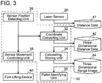
- the controller 30 performs a process to lift and lower the laser sensor 20, a process to perform coordinate conversion on the distance data, and a process to store coordinate-converted three-dimensional distance data to generate a three-dimensional range image by executing a program stored in a memory. Further, the controller 30 performs a process to identify a position, an orientation, and a width of a pallet 100 based on the three-dimensional range image, and the like. That is, as shown in FIG. 3 , the controller 30 functions as a coordinate converting unit 32, a calculating-storing unit 34, a pallet identifying unit 36, a sensor movement controlling unit 38, and a sensor position detecting unit 39.
- a three-dimensional range image 44 of a surrounding object in a space set forward of the forklift 10 is generated by the controller 30 functioning as the aforementioned respective units 32 to 39, and further the position, orientation, and width of the pallet 100 are identified from the generated three-dimensional range image 44. Details of the respective units 32 to 39 will be described together with processes executed by the controller 30 described later.
- the three-dimensional distance data generating process is performed in a state where the forklift 10 is in standby in a vicinity of the pallet 100 to be lifted. That is, as shown in FIG. 4 , the controller 30 firstly drives one of the rear wheels 29 and moves the forklift 10 to approach the pallet 100 so that the pallet 100 is located in front of the vehicle body 12. That is, the forklift 10 is moved to an initial position in front of the pallet to observe the pallet 100 using the laser sensor 20 (S10). For example, the forklift 10 that conveys loads within a factory has preset positions for lifting the loads (the pallet 100).
- the initial position for the forklift 10 to be in standby is preset with respect to the position where the pallet 100 is to be lifted. Due to this, the controller 30 causes the forklift 10 to move autonomously to the preset initial position. It should be noted that, in a case where the forklift 10 is to be driven by a driver personnel, the forklift 10 may be moved to the initial position by the driver personnel, and thereafter the three-dimensional distance data generating process may be started by a switch operation by the driver personnel on the forklift 10.
- the controller 30 moves the laser sensor 20 by using the fork lifting device 40 so that the laser light is emitted to an upper limit of a target observation region 60 (shown in FIG. 5 ) (S12).
- the target observation region 60 is a region where the pallet 100 may be existing.
- the region where the pallet 100 may be existing is determined by sizes of the stage 120 and the pallet 100.
- the laser sensor 20 is moved to the upper limit of the region where the pallet 100 may be existing, so that the pallet 100 can surely be detected.
- the controller 30 acquires distance data 41 using the laser sensor 20 while lowering the fork 22 using the fork lifting device 40 (S14). That is, the laser sensor 20 scans and emits the laser light along the horizontal direction, while at the same time detects reflection of the emitted laser light. On the other hand, since the fork lifting device 40 lifts and lowers the fork 22, the laser sensor 20 moves in the vertical direction. Due to this, the laser light emitted from the laser sensor 20 is scanned in a vertical direction as well. Accordingly, in the process of step S14, the laser light from the laser sensor 20 is scanned in both the horizontal and vertical directions, and detection of the reflections thereof allows an acquisition of observation point groups in the target observation region 60. It should be noted that, a function of the controller 30 realized by the aforementioned processes of steps S12 and S14 corresponds to the sensor moving controlling unit 38 shown in FIG. 3 .
- the controller 30 converts the acquired distance data 41 to three-dimensional distance data 42 in which a height of the laser sensor 20 is reflected (S16). That is, since the controller 30 controls the fork lifting device 40 to lift and lower the fork 22, a position of the fork 22 in the vertical direction (a heightwise position of the laser sensor 20) can be identified. Due to this, when reflection is optically received in the laser sensor 20, the controller 30 reflects height information of the laser sensor 20 at the time of the optical reception to the distance data 41 (at the observation point) and converts it to the three-dimensional distance data 42. Due to this, the three-dimensional distance data 42 indicative of the object existing in the region 50 having the predetermined angular range where the laser light was emitted can be acquired. It should be noted that a function of the controller 30 realized by the process of step S16 as above corresponds to the coordinate converting unit 32 and the sensor position detecting unit 39 shown in FIG 3 .
- the controller 30 selectively extracts only an observation point group within the target observation region 60 from the acquired three-dimensional distance data 42, and stores the same in the memory (S18). Since the height of the laser sensor 20 is reflected in the three-dimensional distance data 42, the observation point group in the target observation region 60 at that height is stored in the memory. It should be noted that a function of the controller 30 realized by the process of step S18 as above corresponds to the calculating-storing unit 34 shown in FIG. 3 .
- the controller 30 determines whether or not a current observing position (height) by the laser sensor 20 is at a lower limit of the target observation region 60 (S20). If it is determined that the current observing position is not at the lower limit of the target observation region (NO to S20), the controller 30 repeats the processes of steps S14 to S18. It should be noted that, if it is determined that the current observing position is at the lower limit of the target observation region (YES to S20), the controller 30 completes the process.
- the observation point groups (three-dimensional distance data 42) for an entirety of the target observation region 60 can be stored in the memory, as a result of which the three-dimensional range image 44 in the target observation region 60 can thereby be generated.
- the controller 30 drives the one of the rear wheels 29 to cause the forklift 10 to approach the pallet 100 so that the pallet 100 is located in front of the vehicle body 12. That is, the controller 30 moves the forklift 10 to the initial position in front of the pallet so as to observe the pallet 100 using the laser sensor 20 (S22).
- the controller 30 moves the laser sensor 20 by using the fork lifting device 40 so that the laser light is emitted to an upper limit of the target observation region 60 (shown in FIG. 5 ) (S24).
- the controller 30 acquires distance data 41 using the laser sensor 20 while lowering the fork 22 using the fork lifting device 40 (S26).
- the controller 30 converts the acquired distance data 41 to three-dimensional distance data 42 in which the height of the laser sensor 20 is reflected (S28). It should be noted that, since the processes of steps S22 to S28 are same as the processes of steps S10 to S16 as aforementioned, the detailed description thereof will be omitted.
- the controller 30 selectively extracts the observation point group in the target observation region 60 from the three-dimensional distance data 42, and a straight line extending in a substantially horizontal direction is extracted from the observation point group that has been extracted (S30).
- the observation point group constituted of reflection that is reflected on the front face of the pallet 100 is located on a single plane. That is, in step S30, the straight line, which is a resultant from scanning the front face of the pallet 100, is extracted from the observation point group.
- the extraction of the straight line can use well-known algorithms called robust estimation, such as RANSAC.
- the controller 30 clusters the point group constituting the extracted straight line (matching the straight line) by using Euclidean distances (S32).
- the front face of the pallet 100 has two openings 110 (into which the tines 22a, 22b of the fork 22 are to be inserted). Due to this, the straight line extracted from the front face of the pallet 100 may be divided by the openings 110 in the front face of the pallet 100.
- a determination on whether or not the straight line is extracted from a single object is made using Euclidean distances in the point group constituting the straight line extracted in step S30.
- well-known methods such as k-means method or kd-tree method may be used.
- the controller 30 performs a process of step S34. Specifically, the controller 30 firstly counts a number of straight line groups that had been clustered (that is a number of clusters), and determines whether or not the counted number of clusters is three (S34). As aforementioned, at a position (height) in the front face of the pallet 100 where the openings 110 are provided, the straight line extending in the substantially horizontal direction (the observation point group) is divided into three by the openings 110 in a laser light horizontal scan (YES to S34). Accordingly, in step S34, a determination can be made on whether or not the extracted straight line corresponds to the front face of the pallet 100 by determining the cluster number is three or not.
- the controller 30 determines whether or not a length of the point group configuring the straight line extracted in step S30 is substantially equal to the width of the pallet 100 (S34).
- a standard of the pallet 100 is normally known in advance.
- a determination can be made on whether or not the straight line on the front surface of the pallet 100 is being extracted by comparing the length of the point group configuring the extracted straight line and a preset value (a value set from the standard of the pallet 100).
- a length W p of the point group configuring the extracted straight line may be obtained by using observation points having maximal and minimal values along an x direction and maximal and minimal values along a y direction within the point group as for example shown in FIG. 8 .
- the controller 30 determines whether or not the obtained length is equal to the width of the pallet 100 by comparing it with the width of the pallet 100 (preset value).
- step S34 if one or more of the conditions are not met (NO to S34), the controller 30 terminates the process on the point group constituting the extracted straight line, and proceeds to a process of step S38. If all of the conditions in the process of step S34 are met (YES to S34), the controller 30 stores the point group constituting the straight line as data that was obtained by observing the front face of the pallet 100 (S36).
- the controller 30 determines whether or not a current observing position (height) of the laser sensor 20 is at a lower limit of the target observation region 60 (S38). Since the controller 30 controls the fork lifting device 40 to lift and lower the fork 22, it is capable of identifying a position of the fork 22 in the vertical direction. Since the laser sensor 20 is mounted on the fork 22, the controller 30 (the sensor position detecting unit 39 shown in FIG. 3 ) is capable of identifying a heightwise position of the laser sensor 20.
- the controller 30 identifies a position, orientation, and width of the pallet 100 from the stored observation point group (the three-dimensional range image 44, which may hereinbelow be termed a convoluted point group) (S40). That is, a straight line group having the cluster number of three, and in which a length of the point group constituting the straight line was determined as being equal to the width of the pallet 100 is obtained from a heightwise range of the front face of the pallet 100 where the openings 110 are provided.
- the position, orientation, and width of the pallet 100 are identified using the data of the observation point group constituting such a straight line group.
- a process of step S40 will be described in detail below. It should be noted that, if the current observing position (height) is not at the lower limit of the target observation region 60 (NO to S38), the controller 30 returns to the process of step S24.
- an x bar, a y bar, and a z bar respectively represent averages of coordinates of N sets of points x i , y i , z i , and represent a center of the front face of the pallet 100.
- a first main axis of this eigenvector corresponds to a vector of the pallet in a lateral side face direction (the y axis in FIG. 9 ), a second main axis corresponds to a vector of the pallet in a top face direction (the z axis in FIG. 9 ), and a third main axis corresponds to a normal vector of the front face of the pallet (the x axis in FIG. 9 ).
- the position and orientation of the pallet in a coordinate system defining its origin at the center of the front face of the pallet are identified. It should be noted that, since the direction of the eigenvector representing the main axes may have its positive and negative directions inverted depending on cases, it is preferable to adjust signs thereof according to its relative relationship with the laser sensor 20.
- a size and width of the pallet 100 can be obtained by projecting the convoluted point group in a plane defined by the first and second main axes of the aforementioned eigenvector. Specifically, a difference between maximal and minimal values of the projection on the first main axis (y axis) corresponds to the width of the pallet 100, and a difference between maximal and minimal values of the projection on the second main axis (z axis) corresponds to a heightwise dimension of the openings 110 of the pallet 100. That is, the size and width of the pallet 100 can thereby be identified. Due to this, the position, orientation, and width of the pallet 100 can be identified.
- averages of the maximal values and the minimal values of the respective projections of the convoluted point group to respective planes defined by the first, second, and third main axes may be set as the center point of the pallet 100. It should be noted that a function of the controller 30 realized by the above process of step S40 corresponds to the pallet identifying unit 36 shown in FIG. 3 .
- the laser sensor 20 is mounted to the fork 22. Due to this, the laser sensor 20 moves up and down as the fork 22 moves up and down. As such, the three-dimensional range image of the pallet 100 can be acquired simply by allowing the laser sensor 20 to scan the laser light in the horizontal direction while moving the fork 22 up and down. Further, since the position, orientation, and width of the pallet 100 are identified using the three-dimensional range image of the pallet 100, a positional displacement in a lateral direction and a displacement related to rotation of the pallet 100 can be detected. As a result, interference between the fork 22 and the pallet 100 can be prevented, and smooth loading operation is thereby enabled.
- a determination can be made on whether or not a load is mounted on the pallet 100 using the laser sensor 20, and further, a position of the load on the pallet 100 can be identified. Due to this, it can be recognized in advance if the load is mounted on the pallet 100 at an unbalanced position, so preventive measures can be taken against the load falling off of the pallet 100. Further, since a shape of the load on the pallet 100 can be identified, a type of the load can also be identified.
- the fork lifting device 40 is an example of "moving mechanism" in the claims
- the calculating-storing unit 34 and the pallet identifying unit 36 are an example of "processor” in the claims.
- the laser light is scanned in the vertical direction by moving the fork up and down in the vertical direction, however, the technique disclosed herein is not limited to this configuration.
- the laser light emitted from the laser sensor 20 may be scanned in the vertical direction by using a tilting mechanism that tilts a distal end of the fork with respect to its proximal end.
- the pallet 100 is detected by extracting straight lines from the observation point groups obtained using the laser sensor 20, however, the technique disclosed herein may directly extract a plane of the front face of the pallet 100 from the observation point groups obtained using the laser sensor 20.
- a front face of the load 130 (plane 1), the front face of the pallet 100 (plane 2), and the floor surface G (plane 3) may be extracted using the laser sensor 20. Due to this, the position, orientation, and width of the pallet 100 can be identified by performing the process of step S40 shown in FIG. 6 on the observation point groups constituting the front face of the pallet 100 (plane 2).
- the RANSAC algorithm can be used similar to the straight line extraction in step S30 of FIG. 6 .
Landscapes
- Engineering & Computer Science (AREA)
- Physics & Mathematics (AREA)
- Transportation (AREA)
- Structural Engineering (AREA)
- General Physics & Mathematics (AREA)
- Mechanical Engineering (AREA)
- Geology (AREA)
- Life Sciences & Earth Sciences (AREA)
- Civil Engineering (AREA)
- Remote Sensing (AREA)
- Radar, Positioning & Navigation (AREA)
- Automation & Control Theory (AREA)
- Aviation & Aerospace Engineering (AREA)
- Electromagnetism (AREA)
- Combustion & Propulsion (AREA)
- Optics & Photonics (AREA)
- Chemical & Material Sciences (AREA)
- Computer Networks & Wireless Communication (AREA)
- Forklifts And Lifting Vehicles (AREA)
- Length Measuring Devices By Optical Means (AREA)
- Measurement Of Optical Distance (AREA)
Abstract
Description
- The present application claims priority based on Japanese Patent Application No.
2015-097487 filed on May 12, 2015 - In a load-lifting operation using a forklift, interferences between a fork and a pallet need to be avoided. In a forklift described in Japanese Patent Application Publication No.
2005-89013 - To perform an accurate load-lifting operation with a forklift, identification accuracy of a pallet position needs to be improved. However, despite being capable of detecting a heightwise displacement of a pallet, the conventional technique had been unable to detect a lateral displacement and a displacement related to rotation.
- The present description discloses a forklift that enables detection of a lateral positional displacement and a displacement related to rotation of a pallet using a simple configuration.
- A forklift disclosed herein may comprise: a fork; a moving mechanism configured to move the fork in a first direction; a laser sensor mounted on the fork, configured to scan laser light in a second direction intersecting the first direction, and measure a distance from the laser sensor to a surrounding object based on reflected light of the scanned laser light; and a processor configured to generate a three-dimensional range image within an emission range to which the laser light is emitted based on distance data acquired when the laser sensor scans the laser light in the second direction while the moving mechanism moves the fork in the first direction.
- In the above forklift, the laser sensor is mounted on the fork, and thus, when the fork moves in the first direction, the laser sensor moves in the first direction together therewith. Due to this, even if the laser sensor is of a one-dimensional scan type that scans the laser light in the second direction, the laser sensor can scan the laser light in the first and second directions by the motion of the fork in the first direction. Due to this, a three-dimensional range image can be acquired by using the laser sensor. This forklift is capable of acquiring the three-dimensional range image, so a positional displacement in a lateral direction and a displacement related to rotation of the pallet can be detected.
-
-
FIG. 1 is a perspective view showing a schematic configuration of a forklift of an embodiment. -
FIG. 2 is a diagram schematically showing a state in which laser light is scanned by the forklift of the embodiment. -
FIG 3 is a block diagram showing a control system of the forklift of the embodiment. -
FIG 4 is a flowchart showing procedures of a process of acquiring a three-dimensional range image using a laser sensor. -
FIG. 5 is a diagram showing a state in which distance data from the laser sensor to a pallet is being acquired by the laser sensor. -
FIG. 6 is a flowchart showing procedures of a process of identifying a position, orientation, and width of the pallet. -
FIG. 7 is a diagram for explaining a method of detecting openings of the pallet. -
FIG. 8 is a diagram for explaining a method of calculating a length of a point group configuring a straight line extracted from acquired three-dimensional distance data. -
FIG. 9 is a diagram showing the pallet and coordinate axes set to the pallet together. -
FIG 10 is a diagram schematically showing a state in which laser light is scanned by using a tilting mechanism configured to tilt a fork. -
FIG. 11 is a diagram for explaining a process of identifying a pallet front face from the three-dimensional range image. - Some of the features of embodiments described below will be listed. It should be noted that the respective technical features described below are independent of one another, and useful solely or in combinations. The combinations thereof are not limited to those described in the claims as originally filed.
- (Feature 1) In a forklift disclosed herein, a moving mechanism may comprise at least a lifting mechanism configured to move a fork up and down in a vertical direction, and a laser sensor may move up and down in the vertical direction as the fork moves up and down in the vertical direction. According to such a configuration, the lifting mechanism that moves the fork up and down in the vertical direction can be used to vertically scan light emitted from the laser sensor.
- (Feature 2) In a forklift disclosed herein, the moving mechanism may comprise at least a tilting mechanism configured to tilt a distal end of the fork with respect to a proximal end of the fork, and the laser light emitted from the laser sensor may be scanned in the vertical direction as the distal end of the fork tilts with respect to the proximal end of the fork. According to such a configuration, the tilting mechanism that tilts the fork can be used to vertically scan the light emitted from the laser sensor.
- (Feature 3) In a forklift disclosed herein, when a generated three-dimensional range image includes a pallet, a processor may be configured to identify a position, an orientation, and a width of a pallet based on the three-dimensional range image. According to such a configuration, the three-dimensional position, orientation, and width of the pallet are identified based on the three-dimensional range image generated from the distance data acquired by the laser sensor, so a positional displacement in a lateral direction and a displacement related to rotation of the pallet can accurately be detected.
- (Feature 4) In a forklift disclosed herein, when the generated three-dimensional range image includes the pallet, the processor may be configured to selectively extract only distance data acquired from a front face of the pallet from the three-dimensional range image and identify the position, the orientation, and the width of the pallet based on a plane at the front face of the pallet identified based on the extracted distance data. According to such a configuration, the three-dimensional position, orientation, and width of the pallet are identified based on the distance data acquired from the front face of the pallet that was extracted from the three-dimensional range image generated from the distance data acquired by the laser sensor. Since positional information of the pallet is identified from the distance data acquired from the front face of the pallet, the positional displacement in the lateral direction and the displacement related to rotation of the pallet can accurately be detected.
- With reference to the drawings, a
forklift 10 of the present embodiment will be described. As shown inFIG. 1 , theforklift 10 is an unmanned forklift, and includes avehicle body 12, amast 24, afork 22, alift chain 26, alaser sensor 20, and acontroller 30. - The
vehicle body 12 is provided with afront wheel 28 and arear wheel 29 at each of its lateral surfaces. Thefront wheels 28 and therear wheels 29 are supported rotatably on thevehicle body 12. One of therear wheels 29 is connected to a driving motor that is not shown, and is configured to be driven to rotate by the driving motor. Further, therear wheel 29 connected to the driving motor is also connected to a steering device that is not shown, and an orientation of the wheel is adjusted by the steering device. The other of therear wheels 29 is a caster wheel, and is rotated and steered by following motions of thevehicle body 12. Thecontroller 30 controls the driving motor and the steering device to allow thevehicle body 12 to run on a road and to change a moving direction of thevehicle body 12. - The
mast 24 is a post mounted to a front surface of thevehicle body 12, and its axis extends in a vertical direction. Thefork 22 is mounted to themast 24 by being able to move in the vertical direction. Further, thefork 22 is configured capable of swinging with respect to themast 24 by a tilting mechanism that is not shown. Thefork 22 includes a pair oftines tines vehicle body 12, and extend forward of thevehicle body 12 from amast 24 side. Thelift chain 26 is disposed on themast 24, and is engaged with thefork 22. When thelift chain 26 is driven by a fork lifting device 40 (shown inFIG 3 ), thefork 22 is lifted and lowered according to a motion of thelift chain 26. A position of thefork 22 in the vertical direction can be identified by a driving amount of thefork lifting device 40. - The
laser sensor 20 is mounted to thefork 22, and is lifted and lowered in the vertical direction together with thefork 22. A position to which thelaser sensor 20 is mounted is between thetine 22a and thetine 22b, and on a backward side (on avehicle body 12 side) relative to a backrest surface of thefork 22. Thelaser sensor 20 is a one-dimensional scanning-type laser sensor that scans the laser light in one direction (the horizontal direction in the present embodiment). Thelaser sensor 20 emits the laser light, and measures a distance to its surrounding object using reflection of the emitted laser light Since thelaser sensor 20 moves up and down according to an up and down motion of thefork 22, a heightwise position of the laser light emitted from thelaser sensor 20 changes according to the motion. In the present embodiment, as shown inFIG 2 , thelaser sensor 20 emits the laser light to a region 50 (seeFIG 1 ) having a predetermined angular range and set forward of theforklift 10, while lifting and lowering in the vertical direction. Due to this, the laser light emitted from thelaser sensor 20 is scanned in the horizontal direction and in a height direction (two-dimensionally), and distance data 41 of a range set forward of theforklift 10 is thereby acquired. Three-dimensional distance data acquired by thelaser sensor 20 is inputted into the controller 30 (seeFIG. 3 ). - It should be noted that, UTM-30LX made by HOKUYO AUTOMATIC CO. LTD, LMS100 made by SICK AG, or the like may for example be used as the
laser sensor 20. - The
controller 30 is constituted of a microprocessor provided with a CPU and the like. Thecontroller 30 is installed in thevehicle body 12. Thecontroller 30 is connected to thelaser sensor 20, the driving motor that drives the one of therear wheels 29, the steering device that adjusts the steering angle of therear wheel 29 connected to the driving motor, the fork lifting device that lifts and lowers thefork 22, and the like as aforementioned, and controls operations thereof. - That is, the
controller 30 performs a process to lift and lower thelaser sensor 20, a process to perform coordinate conversion on the distance data, and a process to store coordinate-converted three-dimensional distance data to generate a three-dimensional range image by executing a program stored in a memory. Further, thecontroller 30 performs a process to identify a position, an orientation, and a width of apallet 100 based on the three-dimensional range image, and the like. That is, as shown inFIG. 3 , thecontroller 30 functions as a coordinate convertingunit 32, a calculating-storingunit 34, apallet identifying unit 36, a sensormovement controlling unit 38, and a sensorposition detecting unit 39. A three-dimensional range image 44 of a surrounding object in a space set forward of theforklift 10 is generated by thecontroller 30 functioning as the aforementionedrespective units 32 to 39, and further the position, orientation, and width of thepallet 100 are identified from the generated three-dimensional range image 44. Details of therespective units 32 to 39 will be described together with processes executed by thecontroller 30 described later. - Next, a process to generate three-
dimensional distance data 42 by thecontroller 30 will be described. The three-dimensional distance data generating process is performed in a state where theforklift 10 is in standby in a vicinity of thepallet 100 to be lifted. That is, as shown inFIG. 4 , thecontroller 30 firstly drives one of therear wheels 29 and moves theforklift 10 to approach thepallet 100 so that thepallet 100 is located in front of thevehicle body 12. That is, theforklift 10 is moved to an initial position in front of the pallet to observe thepallet 100 using the laser sensor 20 (S10). For example, theforklift 10 that conveys loads within a factory has preset positions for lifting the loads (the pallet 100). Due to this, the initial position for theforklift 10 to be in standby is preset with respect to the position where thepallet 100 is to be lifted. Due to this, thecontroller 30 causes theforklift 10 to move autonomously to the preset initial position. It should be noted that, in a case where theforklift 10 is to be driven by a driver personnel, theforklift 10 may be moved to the initial position by the driver personnel, and thereafter the three-dimensional distance data generating process may be started by a switch operation by the driver personnel on theforklift 10. - Next, the
controller 30 moves thelaser sensor 20 by using thefork lifting device 40 so that the laser light is emitted to an upper limit of a target observation region 60 (shown inFIG. 5 ) (S12). Thetarget observation region 60 is a region where thepallet 100 may be existing. For example, as shown inFIG. 5 , in a case where apackage 130 is mounted on thepallet 100, and thepallet 100 is mounted on astage 120, the region where thepallet 100 may be existing (height and width thereof) is determined by sizes of thestage 120 and thepallet 100. In step S12, thelaser sensor 20 is moved to the upper limit of the region where thepallet 100 may be existing, so that thepallet 100 can surely be detected. - Next, the
controller 30 acquires distance data 41 using thelaser sensor 20 while lowering thefork 22 using the fork lifting device 40 (S14). That is, thelaser sensor 20 scans and emits the laser light along the horizontal direction, while at the same time detects reflection of the emitted laser light. On the other hand, since thefork lifting device 40 lifts and lowers thefork 22, thelaser sensor 20 moves in the vertical direction. Due to this, the laser light emitted from thelaser sensor 20 is scanned in a vertical direction as well. Accordingly, in the process of step S14, the laser light from thelaser sensor 20 is scanned in both the horizontal and vertical directions, and detection of the reflections thereof allows an acquisition of observation point groups in thetarget observation region 60. It should be noted that, a function of thecontroller 30 realized by the aforementioned processes of steps S12 and S14 corresponds to the sensor moving controllingunit 38 shown inFIG. 3 . - Next, the
controller 30 converts the acquired distance data 41 to three-dimensional distance data 42 in which a height of thelaser sensor 20 is reflected (S16). That is, since thecontroller 30 controls thefork lifting device 40 to lift and lower thefork 22, a position of thefork 22 in the vertical direction (a heightwise position of the laser sensor 20) can be identified. Due to this, when reflection is optically received in thelaser sensor 20, thecontroller 30 reflects height information of thelaser sensor 20 at the time of the optical reception to the distance data 41 (at the observation point) and converts it to the three-dimensional distance data 42. Due to this, the three-dimensional distance data 42 indicative of the object existing in theregion 50 having the predetermined angular range where the laser light was emitted can be acquired. It should be noted that a function of thecontroller 30 realized by the process of step S16 as above corresponds to the coordinate convertingunit 32 and the sensorposition detecting unit 39 shown inFIG 3 . - Next, the
controller 30 selectively extracts only an observation point group within thetarget observation region 60 from the acquired three-dimensional distance data 42, and stores the same in the memory (S18). Since the height of thelaser sensor 20 is reflected in the three-dimensional distance data 42, the observation point group in thetarget observation region 60 at that height is stored in the memory. It should be noted that a function of thecontroller 30 realized by the process of step S18 as above corresponds to the calculating-storingunit 34 shown inFIG. 3 . - Next, the
controller 30 determines whether or not a current observing position (height) by thelaser sensor 20 is at a lower limit of the target observation region 60 (S20). If it is determined that the current observing position is not at the lower limit of the target observation region (NO to S20), thecontroller 30 repeats the processes of steps S14 to S18. It should be noted that, if it is determined that the current observing position is at the lower limit of the target observation region (YES to S20), thecontroller 30 completes the process. - By repeatedly performing the aforementioned processes, the observation point groups (three-dimensional distance data 42) for an entirety of the
target observation region 60 can be stored in the memory, as a result of which the three-dimensional range image 44 in thetarget observation region 60 can thereby be generated. - Next, the process of identifying the position, orientation, and width of the
pallet 100 will be described with reference toFIGS. 6 and7 . Firstly, thecontroller 30 drives the one of therear wheels 29 to cause theforklift 10 to approach thepallet 100 so that thepallet 100 is located in front of thevehicle body 12. That is, thecontroller 30 moves theforklift 10 to the initial position in front of the pallet so as to observe thepallet 100 using the laser sensor 20 (S22). Next, thecontroller 30 moves thelaser sensor 20 by using thefork lifting device 40 so that the laser light is emitted to an upper limit of the target observation region 60 (shown inFIG. 5 ) (S24). Next, thecontroller 30 acquires distance data 41 using thelaser sensor 20 while lowering thefork 22 using the fork lifting device 40 (S26). Then, thecontroller 30 converts the acquired distance data 41 to three-dimensional distance data 42 in which the height of thelaser sensor 20 is reflected (S28). It should be noted that, since the processes of steps S22 to S28 are same as the processes of steps S10 to S16 as aforementioned, the detailed description thereof will be omitted. - Next, the
controller 30 selectively extracts the observation point group in thetarget observation region 60 from the three-dimensional distance data 42, and a straight line extending in a substantially horizontal direction is extracted from the observation point group that has been extracted (S30). As shown inFIG 7 , the observation point group constituted of reflection that is reflected on the front face of thepallet 100 is located on a single plane. That is, in step S30, the straight line, which is a resultant from scanning the front face of thepallet 100, is extracted from the observation point group. It should be noted that, the extraction of the straight line can use well-known algorithms called robust estimation, such as RANSAC. - Next, the
controller 30 clusters the point group constituting the extracted straight line (matching the straight line) by using Euclidean distances (S32). Here, as shown inFIGS. 5 and7 , the front face of thepallet 100 has two openings 110 (into which thetines fork 22 are to be inserted). Due to this, the straight line extracted from the front face of thepallet 100 may be divided by theopenings 110 in the front face of thepallet 100. Thus, a determination on whether or not the straight line is extracted from a single object (for example, from the front face of the pallet 100) is made using Euclidean distances in the point group constituting the straight line extracted in step S30. It should be noted that, for this clustering, well-known methods such as k-means method or kd-tree method may be used. - Next, the
controller 30 performs a process of step S34. Specifically, thecontroller 30 firstly counts a number of straight line groups that had been clustered (that is a number of clusters), and determines whether or not the counted number of clusters is three (S34). As aforementioned, at a position (height) in the front face of thepallet 100 where theopenings 110 are provided, the straight line extending in the substantially horizontal direction (the observation point group) is divided into three by theopenings 110 in a laser light horizontal scan (YES to S34). Accordingly, in step S34, a determination can be made on whether or not the extracted straight line corresponds to the front face of thepallet 100 by determining the cluster number is three or not. - Next, the
controller 30 determines whether or not a length of the point group configuring the straight line extracted in step S30 is substantially equal to the width of the pallet 100 (S34). Here, a standard of thepallet 100 is normally known in advance. Thus, a determination can be made on whether or not the straight line on the front surface of thepallet 100 is being extracted by comparing the length of the point group configuring the extracted straight line and a preset value (a value set from the standard of the pallet 100). A length Wp of the point group configuring the extracted straight line may be obtained by using observation points having maximal and minimal values along an x direction and maximal and minimal values along a y direction within the point group as for example shown inFIG. 8 . Thecontroller 30 determines whether or not the obtained length is equal to the width of thepallet 100 by comparing it with the width of the pallet 100 (preset value). - In the process of step S34 as aforementioned, if one or more of the conditions are not met (NO to S34), the
controller 30 terminates the process on the point group constituting the extracted straight line, and proceeds to a process of step S38. If all of the conditions in the process of step S34 are met (YES to S34), thecontroller 30 stores the point group constituting the straight line as data that was obtained by observing the front face of the pallet 100 (S36). - Next, the
controller 30 determines whether or not a current observing position (height) of thelaser sensor 20 is at a lower limit of the target observation region 60 (S38). Since thecontroller 30 controls thefork lifting device 40 to lift and lower thefork 22, it is capable of identifying a position of thefork 22 in the vertical direction. Since thelaser sensor 20 is mounted on thefork 22, the controller 30 (the sensorposition detecting unit 39 shown inFIG. 3 ) is capable of identifying a heightwise position of thelaser sensor 20. If the current observing position (height) is at the lower limit of the target observation region 60 (YES to S38), thecontroller 30 identifies a position, orientation, and width of thepallet 100 from the stored observation point group (the three-dimensional range image 44, which may hereinbelow be termed a convoluted point group) (S40). That is, a straight line group having the cluster number of three, and in which a length of the point group constituting the straight line was determined as being equal to the width of thepallet 100 is obtained from a heightwise range of the front face of thepallet 100 where theopenings 110 are provided. In step S40, the position, orientation, and width of thepallet 100 are identified using the data of the observation point group constituting such a straight line group. A process of step S40 will be described in detail below. It should be noted that, if the current observing position (height) is not at the lower limit of the target observation region 60 (NO to S38), thecontroller 30 returns to the process of step S24. - Next, a method of identifying the position, orientation, and width of the
pallet 100 in step S40 will be described. Firstly, a variance-covariance matrix as in the following formula (1) will be considered to obtain main axes (that is, an x axis, a y axis, and a z axis shown inFIG 9 ) from variations of respective points (xi, yi, zi) (i=1 to N) in N sets of convoluted point groups.
[Math 1]
- In the above formula (1), an x bar, a y bar, and a z bar respectively represent averages of coordinates of N sets of points xi, yi, zi, and represent a center of the front face of the
pallet 100. - Next, an eigenvector in a three-dimensional space is calculated from this matrix. A first main axis of this eigenvector corresponds to a vector of the pallet in a lateral side face direction (the y axis in
FIG. 9 ), a second main axis corresponds to a vector of the pallet in a top face direction (the z axis inFIG. 9 ), and a third main axis corresponds to a normal vector of the front face of the pallet (the x axis inFIG. 9 ). According to this, the position and orientation of the pallet in a coordinate system defining its origin at the center of the front face of the pallet are identified. It should be noted that, since the direction of the eigenvector representing the main axes may have its positive and negative directions inverted depending on cases, it is preferable to adjust signs thereof according to its relative relationship with thelaser sensor 20. - Here, a size and width of the
pallet 100 can be obtained by projecting the convoluted point group in a plane defined by the first and second main axes of the aforementioned eigenvector. Specifically, a difference between maximal and minimal values of the projection on the first main axis (y axis) corresponds to the width of thepallet 100, and a difference between maximal and minimal values of the projection on the second main axis (z axis) corresponds to a heightwise dimension of theopenings 110 of thepallet 100. That is, the size and width of thepallet 100 can thereby be identified. Due to this, the position, orientation, and width of thepallet 100 can be identified. Further, averages of the maximal values and the minimal values of the respective projections of the convoluted point group to respective planes defined by the first, second, and third main axes may be set as the center point of thepallet 100. It should be noted that a function of thecontroller 30 realized by the above process of step S40 corresponds to thepallet identifying unit 36 shown inFIG. 3 . - In the
forklift 10 of the aforementioned embodiment, thelaser sensor 20 is mounted to thefork 22. Due to this, thelaser sensor 20 moves up and down as thefork 22 moves up and down. As such, the three-dimensional range image of thepallet 100 can be acquired simply by allowing thelaser sensor 20 to scan the laser light in the horizontal direction while moving thefork 22 up and down. Further, since the position, orientation, and width of thepallet 100 are identified using the three-dimensional range image of thepallet 100, a positional displacement in a lateral direction and a displacement related to rotation of thepallet 100 can be detected. As a result, interference between thefork 22 and thepallet 100 can be prevented, and smooth loading operation is thereby enabled. - Further, in the
forklift 10 of the present embodiment, a determination can be made on whether or not a load is mounted on thepallet 100 using thelaser sensor 20, and further, a position of the load on thepallet 100 can be identified. Due to this, it can be recognized in advance if the load is mounted on thepallet 100 at an unbalanced position, so preventive measures can be taken against the load falling off of thepallet 100. Further, since a shape of the load on thepallet 100 can be identified, a type of the load can also be identified. - Finally, corresponding relationships between the aforementioned embodiment and the claims will be described. The
fork lifting device 40 is an example of "moving mechanism" in the claims, and the calculating-storingunit 34 and thepallet identifying unit 36 are an example of "processor" in the claims. - The embodiments have been described in detail, however, these are mere exemplary indications and thus do not limit the scope of the claims. The art described in the claims include modifications and variations of the specific examples presented above.
- For example, in the present embodiment, the laser light is scanned in the vertical direction by moving the fork up and down in the vertical direction, however, the technique disclosed herein is not limited to this configuration. For example, as shown in
FIG. 10 , the laser light emitted from thelaser sensor 20 may be scanned in the vertical direction by using a tilting mechanism that tilts a distal end of the fork with respect to its proximal end. - Further, in the present embodiment, the
pallet 100 is detected by extracting straight lines from the observation point groups obtained using thelaser sensor 20, however, the technique disclosed herein may directly extract a plane of the front face of thepallet 100 from the observation point groups obtained using thelaser sensor 20. For example, as shown inFIG. 11 , when thepallet 100 is directly placed on a floor surface G and aload 130 is mounted on thepallet 100, a front face of the load 130 (plane 1), the front face of the pallet 100 (plane 2), and the floor surface G (plane 3) may be extracted using thelaser sensor 20. Due to this, the position, orientation, and width of thepallet 100 can be identified by performing the process of step S40 shown inFIG. 6 on the observation point groups constituting the front face of the pallet 100 (plane 2). It should be noted that for the plane extraction, the RANSAC algorithm can be used similar to the straight line extraction in step S30 ofFIG. 6 . - Technical features described in the description and the drawings may technically be useful alone or in various combinations, and are not limited to the combinations as originally claimed. Further, the art described in the description and the drawings may concurrently achieve a plurality of aims, and technical significance thereof resides in achieving any one of such aims.
Claims (5)
- A forklift comprising:a fork;a moving mechanism configured to move the fork in a first direction;a laser sensor mounted on the fork, configured to scan laser light in a second direction intersecting the first direction, and measure a distance from the laser sensor to a surrounding object based on reflection of the scanned laser light; anda processor configured to generate a three-dimensional range image within an emission range to which the laser light is emitted based on distance data acquired when the laser sensor scans the laser light in the second direction while the moving mechanism moves the fork in the first direction.
- The forklift according to claim 1, wherein
the moving mechanism comprises at least a lifting mechanism configured to move the fork up and down in a vertical direction, and
the laser sensor moves up and down in the vertical direction as the fork moves up and down in the vertical direction. - The forklift according to claim 1 or 2, wherein
the moving mechanism comprises at least a tilting mechanism configured to tilt a distal end of the fork with respect to a proximal end of the fork, and
the laser light emitted from the laser sensor is scanned in the vertical direction as the distal end of the fork tilts with respect to the proximal end of the fork. - The forklift according to any one of claims 1 to 3, wherein
when the generated three-dimensional range image includes a pallet, the processor is configured to identify a position, an orientation, and a width of the pallet based on the three-dimensional range image. - The forklift according to claim 4, wherein
when the generated three-dimensional range image includes the pallet, the processor is configured to selectively extract only distance data acquired from a front face of the pallet from the three-dimensional range image and identify the position, the orientation, and the width of the pallet based on a plane at the front face of the pallet identified based on the extracted distance data.
Applications Claiming Priority (2)
| Application Number | Priority Date | Filing Date | Title |
|---|---|---|---|
| JP2015097487A JP6542574B2 (en) | 2015-05-12 | 2015-05-12 | forklift |
| PCT/JP2016/061596 WO2016181733A1 (en) | 2015-05-12 | 2016-04-08 | Forklift |
Publications (3)
| Publication Number | Publication Date |
|---|---|
| EP3296250A1 true EP3296250A1 (en) | 2018-03-21 |
| EP3296250A4 EP3296250A4 (en) | 2018-04-04 |
| EP3296250B1 EP3296250B1 (en) | 2019-03-20 |
Family
ID=57247902
Family Applications (1)
| Application Number | Title | Priority Date | Filing Date |
|---|---|---|---|
| EP16792458.8A Active EP3296250B1 (en) | 2015-05-12 | 2016-04-08 | Forklift |
Country Status (5)
| Country | Link |
|---|---|
| US (1) | US10850961B2 (en) |
| EP (1) | EP3296250B1 (en) |
| JP (1) | JP6542574B2 (en) |
| CN (1) | CN107531469B (en) |
| WO (1) | WO2016181733A1 (en) |
Families Citing this family (44)
| Publication number | Priority date | Publication date | Assignee | Title |
|---|---|---|---|---|
| JP2017178567A (en) * | 2016-03-30 | 2017-10-05 | 株式会社豊田中央研究所 | forklift |
| CN106672859B (en) * | 2017-01-05 | 2018-11-09 | 深圳市有光图像科技有限公司 | A kind of method and fork truck based on fork truck visual identity pallet |
| JP6972600B2 (en) * | 2017-03-22 | 2021-11-24 | 日本電気株式会社 | In-vehicle equipment, cargo handling equipment, control circuits, control methods, and programs |
| JP6880884B2 (en) * | 2017-03-22 | 2021-06-02 | 日本電気株式会社 | In-vehicle devices, cargo handling machines, control circuits, control methods, and programs |
| JP6822255B2 (en) * | 2017-03-22 | 2021-01-27 | 日本電気株式会社 | In-vehicle devices, control circuits, control methods, and programs |
| JP6880950B2 (en) * | 2017-04-05 | 2021-06-02 | 村田機械株式会社 | Depression detection device, transfer device, and recess detection method |
| KR102359931B1 (en) * | 2017-04-28 | 2022-02-07 | 현대자동차 주식회사 | Fork lifter system, and control method thereof |
| WO2019163378A1 (en) * | 2018-02-23 | 2019-08-29 | コニカミノルタ株式会社 | Forklift image processing device and control program |
| WO2020066847A1 (en) * | 2018-09-28 | 2020-04-02 | パナソニックIpマネジメント株式会社 | Measurement device and measurement method |
| CN109850810B (en) * | 2019-03-13 | 2020-09-25 | 南京实邦智能科技有限公司 | Forklift motion control method and device |
| CN110082720A (en) * | 2019-04-04 | 2019-08-02 | 南京实邦智能科技有限公司 | Tray information acquisition device, control method and pallet carrying vehicle |
| US11591197B2 (en) * | 2019-04-05 | 2023-02-28 | The Raymond Corporation | Load handling module for a material handling vehicle |
| JP7095653B2 (en) * | 2019-05-21 | 2022-07-05 | 株式会社豊田自動織機 | Loading position detection device for automatic operation forklifts |
| CN110428209B (en) | 2019-08-16 | 2020-10-27 | 灵动科技(北京)有限公司 | Checking equipment, checking management system and checking method |
| JP7172922B2 (en) * | 2019-09-05 | 2022-11-16 | 株式会社豊田自動織機 | FORKLIFT AND CONTAINER POSTURE DETECTION METHOD |
| JP7272197B2 (en) | 2019-09-13 | 2023-05-12 | 株式会社豊田自動織機 | Position and orientation estimation device |
| WO2021171974A1 (en) * | 2020-02-27 | 2021-09-02 | 三菱重工業株式会社 | Control device, mobile body, movement control system, control method, and program |
| DE102020105804A1 (en) | 2020-03-04 | 2021-09-09 | Jungheinrich Aktiengesellschaft | System for inspecting a warehouse |
| JP7086148B2 (en) | 2020-08-31 | 2022-06-17 | 三菱ロジスネクスト株式会社 | Pallet detectors, forklifts, pallet detection methods, and programs |
| CN116615698A (en) * | 2020-12-11 | 2023-08-18 | 德马吉森精机株式会社 | Self-propelled device |
| JP2022106386A (en) * | 2021-01-07 | 2022-07-20 | グローリー株式会社 | Dimension measuring device and dimension measuring method |
| JP7482808B2 (en) * | 2021-02-05 | 2024-05-14 | 三菱ロジスネクスト株式会社 | MOBILE BODY CONTROL METHOD, MOBILE BODY, AND PROGRAM |
| JPWO2022168377A1 (en) * | 2021-02-05 | 2022-08-11 | ||
| JP7179102B2 (en) * | 2021-02-05 | 2022-11-28 | 三菱ロジスネクスト株式会社 | Mobile object control method, mobile object and program |
| JP7578499B2 (en) * | 2021-02-12 | 2024-11-06 | 矢崎エナジーシステム株式会社 | Cargo handling condition determination device, driving assistance system, and driving assistance program |
| DE102021103799A1 (en) * | 2021-02-18 | 2022-08-18 | Jungheinrich Aktiengesellschaft | INDUSTRIAL TRUCK WITH DETECTION DEVICES ON THE FORKS |
| JP7556308B2 (en) * | 2021-02-22 | 2024-09-26 | 株式会社豊田自動織機 | Position and orientation estimation device |
| JP2022140049A (en) * | 2021-03-12 | 2022-09-26 | オムロン株式会社 | Conveyance state detection device, conveyance state detection system comprising the same, conveyance state detection method, and conveyance state detection program |
| JP2022140064A (en) * | 2021-03-12 | 2022-09-26 | オムロン株式会社 | Conveyance unit, conveyance method, and conveyance program |
| JP2022140048A (en) * | 2021-03-12 | 2022-09-26 | オムロン株式会社 | Carrier detection device, carrier detection system comprising the same, carrier detection method, and carrier detection program |
| JP2022140045A (en) * | 2021-03-12 | 2022-09-26 | オムロン株式会社 | Conveyance propriety determination device, range finder, conveyance unit, conveyance propriety determination method, and conveyance propriety determination program |
| JP7325465B2 (en) * | 2021-03-15 | 2023-08-14 | 三菱重工業株式会社 | Mobile object control method, mobile object and program |
| US12260627B2 (en) * | 2021-05-19 | 2025-03-25 | Nakanishi Metal Works Co., Ltd. | Unmanned forklift |
| JP7472082B2 (en) | 2021-07-02 | 2024-04-22 | 三菱ロジスネクスト株式会社 | How to set up an unmanned forklift |
| JP7559707B2 (en) * | 2021-08-24 | 2024-10-02 | 株式会社豊田自動織機 | forklift |
| JP2025094281A (en) * | 2022-02-21 | 2025-06-25 | 株式会社日立製作所 | Object orientation calculation device and object orientation calculation method |
| WO2023192313A1 (en) * | 2022-03-28 | 2023-10-05 | Seegrid Corporation | Continuous and discrete estimation of payload engagement/disengagement sensing |
| CA3245345A1 (en) * | 2022-03-28 | 2023-10-05 | Seegrid Corporation | Dense data registration from an actuatable vehicle-mounted sensor |
| PL4324782T3 (en) * | 2022-08-16 | 2025-07-21 | Palfinger Ag | Forklift |
| JP7618366B2 (en) * | 2022-11-24 | 2025-01-21 | 三菱ロジスネクスト株式会社 | forklift |
| US20240208736A1 (en) * | 2022-12-27 | 2024-06-27 | Gideon Brothers d.o.o. | Ai-powered load stability estimation for pallet handling |
| JP7669416B2 (en) * | 2023-05-15 | 2025-04-28 | 三菱ロジスネクスト株式会社 | Method for dealing with floor inclination and system for dealing with floor inclination |
| JP2025018511A (en) | 2023-07-27 | 2025-02-06 | 株式会社小松製作所 | Identification system, identification method and work vehicle |
| WO2025255580A2 (en) * | 2024-06-07 | 2025-12-11 | Rehrig Pacific Company | Validation system |
Family Cites Families (11)
| Publication number | Priority date | Publication date | Assignee | Title |
|---|---|---|---|---|
| JPS5957898A (en) * | 1982-09-28 | 1984-04-03 | 株式会社豊田自動織機製作所 | Method of controlling cargo work in unmanned forklift |
| JPH0279398U (en) * | 1988-12-05 | 1990-06-19 | ||
| JPH11278799A (en) * | 1998-03-24 | 1999-10-12 | Mitsubishi Electric Corp | Unloading control device for unmanned forklift and unloading control method for unmanned forklift |
| DE10323641A1 (en) * | 2003-05-26 | 2005-01-05 | Daimlerchrysler Ag | Movable sensor device on the load means of a forklift |
| JP2005089013A (en) * | 2003-09-12 | 2005-04-07 | Nippon Yusoki Co Ltd | Forklift |
| US8192137B2 (en) | 2004-05-03 | 2012-06-05 | Jervis B. Webb Company | Automatic transport loading system and method |
| CN201237644Y (en) * | 2008-03-21 | 2009-05-13 | 上海海镭激光科技有限公司 | Reversing alarm device for fork truck and loader |
| BE1018160A3 (en) * | 2008-05-26 | 2010-06-01 | Egemin Nv | Automatic guided vehicle, has load handling device connected to onboard computer, where vehicle is provided with detection unit, which comprises single sensor for determining relative position of load handling device |
| US8169596B2 (en) * | 2009-08-17 | 2012-05-01 | Seegrid Corporation | System and method using a multi-plane curtain |
| US8538577B2 (en) * | 2010-03-05 | 2013-09-17 | Crown Equipment Limited | Method and apparatus for sensing object load engagement, transportation and disengagement by automated vehicles |
| US8965561B2 (en) * | 2013-03-15 | 2015-02-24 | Cybernet Systems Corporation | Automated warehousing using robotic forklifts |
-
2015
- 2015-05-12 JP JP2015097487A patent/JP6542574B2/en active Active
-
2016
- 2016-04-08 WO PCT/JP2016/061596 patent/WO2016181733A1/en not_active Ceased
- 2016-04-08 CN CN201680027308.2A patent/CN107531469B/en active Active
- 2016-04-08 EP EP16792458.8A patent/EP3296250B1/en active Active
- 2016-04-08 US US15/572,809 patent/US10850961B2/en active Active
Also Published As
| Publication number | Publication date |
|---|---|
| US20180155169A1 (en) | 2018-06-07 |
| WO2016181733A1 (en) | 2016-11-17 |
| US10850961B2 (en) | 2020-12-01 |
| JP6542574B2 (en) | 2019-07-10 |
| EP3296250A4 (en) | 2018-04-04 |
| CN107531469A (en) | 2018-01-02 |
| JP2016210586A (en) | 2016-12-15 |
| CN107531469B (en) | 2019-07-05 |
| EP3296250B1 (en) | 2019-03-20 |
Similar Documents
| Publication | Publication Date | Title |
|---|---|---|
| EP3296250B1 (en) | Forklift | |
| EP3284712B1 (en) | Forklift | |
| EP3225584A1 (en) | Forklift | |
| EP3000771B1 (en) | Fork-lift truck | |
| US9828223B2 (en) | Fork-lift truck and method for operating a fork-lift truck | |
| US10248123B2 (en) | Mobile apparatus | |
| JP7103077B2 (en) | Remote control system for forklifts | |
| US7219769B2 (en) | Industrial vehicle equipped with load handling operation control apparatus | |
| JP3921968B2 (en) | Position detection method and position detection apparatus | |
| US20080011554A1 (en) | Movable sensor device on the loading means of a forklift | |
| US11524880B2 (en) | Forklift and method for detecting posture of container | |
| US12269722B2 (en) | Method for operating a means of transport | |
| CA3229505A1 (en) | Method for operating a means of transport | |
| JP7488991B2 (en) | Industrial Vehicles | |
| KR102868973B1 (en) | Object-following cart | |
| JP7863827B2 (en) | Object detection device, object detection method, and industrial vehicle | |
| EP4603938A1 (en) | Position identification system | |
| JP2026045779A (en) | Mobile object, calculation method, and program | |
| WO2026048091A1 (en) | Mobile body, control method, and program | |
| JP2022128063A (en) | Position and posture estimation device | |
| JP2023064294A (en) | Position posture estimation device | |
| HK40085249A (en) | Systems and methods for material handling vehicle travel control based on object detection systems | |
| WO2026048092A1 (en) | Mobile body, control method, and program |
Legal Events
| Date | Code | Title | Description |
|---|---|---|---|
| STAA | Information on the status of an ep patent application or granted ep patent |
Free format text: STATUS: THE INTERNATIONAL PUBLICATION HAS BEEN MADE |
|
| PUAI | Public reference made under article 153(3) epc to a published international application that has entered the european phase |
Free format text: ORIGINAL CODE: 0009012 |
|
| STAA | Information on the status of an ep patent application or granted ep patent |
Free format text: STATUS: REQUEST FOR EXAMINATION WAS MADE |
|
| 17P | Request for examination filed |
Effective date: 20171130 |
|
| AK | Designated contracting states |
Kind code of ref document: A1 Designated state(s): AL AT BE BG CH CY CZ DE DK EE ES FI FR GB GR HR HU IE IS IT LI LT LU LV MC MK MT NL NO PL PT RO RS SE SI SK SM TR |
|
| AX | Request for extension of the european patent |
Extension state: BA ME |
|
| A4 | Supplementary search report drawn up and despatched |
Effective date: 20180302 |
|
| RIC1 | Information provided on ipc code assigned before grant |
Ipc: G01B 11/26 20060101ALI20180226BHEP Ipc: B66F 9/06 20060101ALI20180226BHEP Ipc: B66F 9/24 20060101ALI20180226BHEP Ipc: G01B 11/02 20060101ALI20180226BHEP Ipc: G01B 11/00 20060101AFI20180226BHEP Ipc: G05D 1/02 20060101ALI20180226BHEP |
|
| DAV | Request for validation of the european patent (deleted) | ||
| DAX | Request for extension of the european patent (deleted) | ||
| REG | Reference to a national code |
Ref country code: DE Ref legal event code: R079 Ref document number: 602016011403 Country of ref document: DE Free format text: PREVIOUS MAIN CLASS: B66F0009240000 Ipc: G01B0011000000 |
|
| GRAP | Despatch of communication of intention to grant a patent |
Free format text: ORIGINAL CODE: EPIDOSNIGR1 |
|
| STAA | Information on the status of an ep patent application or granted ep patent |
Free format text: STATUS: GRANT OF PATENT IS INTENDED |
|
| INTG | Intention to grant announced |
Effective date: 20181109 |
|
| RIC1 | Information provided on ipc code assigned before grant |
Ipc: G01B 11/00 20060101AFI20181022BHEP Ipc: B66F 9/24 20060101ALI20181022BHEP Ipc: G05D 1/02 20060101ALI20181022BHEP Ipc: B66F 9/06 20060101ALI20181022BHEP Ipc: G01B 11/02 20060101ALI20181022BHEP Ipc: G01B 11/26 20060101ALI20181022BHEP |
|
| GRAS | Grant fee paid |
Free format text: ORIGINAL CODE: EPIDOSNIGR3 |
|
| GRAA | (expected) grant |
Free format text: ORIGINAL CODE: 0009210 |
|
| STAA | Information on the status of an ep patent application or granted ep patent |
Free format text: STATUS: THE PATENT HAS BEEN GRANTED |
|
| AK | Designated contracting states |
Kind code of ref document: B1 Designated state(s): AL AT BE BG CH CY CZ DE DK EE ES FI FR GB GR HR HU IE IS IT LI LT LU LV MC MK MT NL NO PL PT RO RS SE SI SK SM TR |
|
| REG | Reference to a national code |
Ref country code: GB Ref legal event code: FG4D |
|
| REG | Reference to a national code |
Ref country code: CH Ref legal event code: EP |
|
| REG | Reference to a national code |
Ref country code: DE Ref legal event code: R096 Ref document number: 602016011403 Country of ref document: DE |
|
| REG | Reference to a national code |
Ref country code: AT Ref legal event code: REF Ref document number: 1111001 Country of ref document: AT Kind code of ref document: T Effective date: 20190415 |
|
| REG | Reference to a national code |
Ref country code: SE Ref legal event code: TRGR |
|
| REG | Reference to a national code |
Ref country code: IE Ref legal event code: FG4D |
|
| REG | Reference to a national code |
Ref country code: NL Ref legal event code: MP Effective date: 20190320 |
|
| PG25 | Lapsed in a contracting state [announced via postgrant information from national office to epo] |
Ref country code: LT Free format text: LAPSE BECAUSE OF FAILURE TO SUBMIT A TRANSLATION OF THE DESCRIPTION OR TO PAY THE FEE WITHIN THE PRESCRIBED TIME-LIMIT Effective date: 20190320 Ref country code: NO Free format text: LAPSE BECAUSE OF FAILURE TO SUBMIT A TRANSLATION OF THE DESCRIPTION OR TO PAY THE FEE WITHIN THE PRESCRIBED TIME-LIMIT Effective date: 20190620 Ref country code: FI Free format text: LAPSE BECAUSE OF FAILURE TO SUBMIT A TRANSLATION OF THE DESCRIPTION OR TO PAY THE FEE WITHIN THE PRESCRIBED TIME-LIMIT Effective date: 20190320 |
|
| REG | Reference to a national code |
Ref country code: LT Ref legal event code: MG4D |
|
| PG25 | Lapsed in a contracting state [announced via postgrant information from national office to epo] |
Ref country code: BG Free format text: LAPSE BECAUSE OF FAILURE TO SUBMIT A TRANSLATION OF THE DESCRIPTION OR TO PAY THE FEE WITHIN THE PRESCRIBED TIME-LIMIT Effective date: 20190620 Ref country code: LV Free format text: LAPSE BECAUSE OF FAILURE TO SUBMIT A TRANSLATION OF THE DESCRIPTION OR TO PAY THE FEE WITHIN THE PRESCRIBED TIME-LIMIT Effective date: 20190320 Ref country code: NL Free format text: LAPSE BECAUSE OF FAILURE TO SUBMIT A TRANSLATION OF THE DESCRIPTION OR TO PAY THE FEE WITHIN THE PRESCRIBED TIME-LIMIT Effective date: 20190320 Ref country code: RS Free format text: LAPSE BECAUSE OF FAILURE TO SUBMIT A TRANSLATION OF THE DESCRIPTION OR TO PAY THE FEE WITHIN THE PRESCRIBED TIME-LIMIT Effective date: 20190320 Ref country code: HR Free format text: LAPSE BECAUSE OF FAILURE TO SUBMIT A TRANSLATION OF THE DESCRIPTION OR TO PAY THE FEE WITHIN THE PRESCRIBED TIME-LIMIT Effective date: 20190320 Ref country code: GR Free format text: LAPSE BECAUSE OF FAILURE TO SUBMIT A TRANSLATION OF THE DESCRIPTION OR TO PAY THE FEE WITHIN THE PRESCRIBED TIME-LIMIT Effective date: 20190621 |
|
| REG | Reference to a national code |
Ref country code: AT Ref legal event code: MK05 Ref document number: 1111001 Country of ref document: AT Kind code of ref document: T Effective date: 20190320 |
|
| PG25 | Lapsed in a contracting state [announced via postgrant information from national office to epo] |
Ref country code: CZ Free format text: LAPSE BECAUSE OF FAILURE TO SUBMIT A TRANSLATION OF THE DESCRIPTION OR TO PAY THE FEE WITHIN THE PRESCRIBED TIME-LIMIT Effective date: 20190320 Ref country code: RO Free format text: LAPSE BECAUSE OF FAILURE TO SUBMIT A TRANSLATION OF THE DESCRIPTION OR TO PAY THE FEE WITHIN THE PRESCRIBED TIME-LIMIT Effective date: 20190320 Ref country code: IT Free format text: LAPSE BECAUSE OF FAILURE TO SUBMIT A TRANSLATION OF THE DESCRIPTION OR TO PAY THE FEE WITHIN THE PRESCRIBED TIME-LIMIT Effective date: 20190320 Ref country code: PT Free format text: LAPSE BECAUSE OF FAILURE TO SUBMIT A TRANSLATION OF THE DESCRIPTION OR TO PAY THE FEE WITHIN THE PRESCRIBED TIME-LIMIT Effective date: 20190720 Ref country code: AL Free format text: LAPSE BECAUSE OF FAILURE TO SUBMIT A TRANSLATION OF THE DESCRIPTION OR TO PAY THE FEE WITHIN THE PRESCRIBED TIME-LIMIT Effective date: 20190320 Ref country code: SK Free format text: LAPSE BECAUSE OF FAILURE TO SUBMIT A TRANSLATION OF THE DESCRIPTION OR TO PAY THE FEE WITHIN THE PRESCRIBED TIME-LIMIT Effective date: 20190320 Ref country code: EE Free format text: LAPSE BECAUSE OF FAILURE TO SUBMIT A TRANSLATION OF THE DESCRIPTION OR TO PAY THE FEE WITHIN THE PRESCRIBED TIME-LIMIT Effective date: 20190320 Ref country code: ES Free format text: LAPSE BECAUSE OF FAILURE TO SUBMIT A TRANSLATION OF THE DESCRIPTION OR TO PAY THE FEE WITHIN THE PRESCRIBED TIME-LIMIT Effective date: 20190320 |
|
| PG25 | Lapsed in a contracting state [announced via postgrant information from national office to epo] |
Ref country code: SM Free format text: LAPSE BECAUSE OF FAILURE TO SUBMIT A TRANSLATION OF THE DESCRIPTION OR TO PAY THE FEE WITHIN THE PRESCRIBED TIME-LIMIT Effective date: 20190320 Ref country code: PL Free format text: LAPSE BECAUSE OF FAILURE TO SUBMIT A TRANSLATION OF THE DESCRIPTION OR TO PAY THE FEE WITHIN THE PRESCRIBED TIME-LIMIT Effective date: 20190320 |
|
| REG | Reference to a national code |
Ref country code: CH Ref legal event code: PL |
|
| REG | Reference to a national code |
Ref country code: BE Ref legal event code: MM Effective date: 20190430 |
|
| PG25 | Lapsed in a contracting state [announced via postgrant information from national office to epo] |
Ref country code: IS Free format text: LAPSE BECAUSE OF FAILURE TO SUBMIT A TRANSLATION OF THE DESCRIPTION OR TO PAY THE FEE WITHIN THE PRESCRIBED TIME-LIMIT Effective date: 20190720 Ref country code: AT Free format text: LAPSE BECAUSE OF FAILURE TO SUBMIT A TRANSLATION OF THE DESCRIPTION OR TO PAY THE FEE WITHIN THE PRESCRIBED TIME-LIMIT Effective date: 20190320 Ref country code: LU Free format text: LAPSE BECAUSE OF NON-PAYMENT OF DUE FEES Effective date: 20190408 |
|
| REG | Reference to a national code |
Ref country code: DE Ref legal event code: R097 Ref document number: 602016011403 Country of ref document: DE |
|
| PLBE | No opposition filed within time limit |
Free format text: ORIGINAL CODE: 0009261 |
|
| STAA | Information on the status of an ep patent application or granted ep patent |
Free format text: STATUS: NO OPPOSITION FILED WITHIN TIME LIMIT |
|
| PG25 | Lapsed in a contracting state [announced via postgrant information from national office to epo] |
Ref country code: DK Free format text: LAPSE BECAUSE OF FAILURE TO SUBMIT A TRANSLATION OF THE DESCRIPTION OR TO PAY THE FEE WITHIN THE PRESCRIBED TIME-LIMIT Effective date: 20190320 Ref country code: CH Free format text: LAPSE BECAUSE OF NON-PAYMENT OF DUE FEES Effective date: 20190430 Ref country code: LI Free format text: LAPSE BECAUSE OF NON-PAYMENT OF DUE FEES Effective date: 20190430 Ref country code: MC Free format text: LAPSE BECAUSE OF FAILURE TO SUBMIT A TRANSLATION OF THE DESCRIPTION OR TO PAY THE FEE WITHIN THE PRESCRIBED TIME-LIMIT Effective date: 20190320 |
|
| 26N | No opposition filed |
Effective date: 20200102 |
|
| PG25 | Lapsed in a contracting state [announced via postgrant information from national office to epo] |
Ref country code: BE Free format text: LAPSE BECAUSE OF NON-PAYMENT OF DUE FEES Effective date: 20190430 Ref country code: SI Free format text: LAPSE BECAUSE OF FAILURE TO SUBMIT A TRANSLATION OF THE DESCRIPTION OR TO PAY THE FEE WITHIN THE PRESCRIBED TIME-LIMIT Effective date: 20190320 |
|
| PG25 | Lapsed in a contracting state [announced via postgrant information from national office to epo] |
Ref country code: TR Free format text: LAPSE BECAUSE OF FAILURE TO SUBMIT A TRANSLATION OF THE DESCRIPTION OR TO PAY THE FEE WITHIN THE PRESCRIBED TIME-LIMIT Effective date: 20190320 |
|
| PG25 | Lapsed in a contracting state [announced via postgrant information from national office to epo] |
Ref country code: IE Free format text: LAPSE BECAUSE OF NON-PAYMENT OF DUE FEES Effective date: 20190408 |
|
| GBPC | Gb: european patent ceased through non-payment of renewal fee |
Effective date: 20200408 |
|
| PG25 | Lapsed in a contracting state [announced via postgrant information from national office to epo] |
Ref country code: GB Free format text: LAPSE BECAUSE OF NON-PAYMENT OF DUE FEES Effective date: 20200408 |
|
| PG25 | Lapsed in a contracting state [announced via postgrant information from national office to epo] |
Ref country code: CY Free format text: LAPSE BECAUSE OF FAILURE TO SUBMIT A TRANSLATION OF THE DESCRIPTION OR TO PAY THE FEE WITHIN THE PRESCRIBED TIME-LIMIT Effective date: 20190320 |
|
| PG25 | Lapsed in a contracting state [announced via postgrant information from national office to epo] |
Ref country code: HU Free format text: LAPSE BECAUSE OF FAILURE TO SUBMIT A TRANSLATION OF THE DESCRIPTION OR TO PAY THE FEE WITHIN THE PRESCRIBED TIME-LIMIT; INVALID AB INITIO Effective date: 20160408 Ref country code: MT Free format text: LAPSE BECAUSE OF FAILURE TO SUBMIT A TRANSLATION OF THE DESCRIPTION OR TO PAY THE FEE WITHIN THE PRESCRIBED TIME-LIMIT Effective date: 20190320 |
|
| PG25 | Lapsed in a contracting state [announced via postgrant information from national office to epo] |
Ref country code: MK Free format text: LAPSE BECAUSE OF FAILURE TO SUBMIT A TRANSLATION OF THE DESCRIPTION OR TO PAY THE FEE WITHIN THE PRESCRIBED TIME-LIMIT Effective date: 20190320 |
|
| P01 | Opt-out of the competence of the unified patent court (upc) registered |
Effective date: 20230519 |
|
| PGFP | Annual fee paid to national office [announced via postgrant information from national office to epo] |
Ref country code: SE Payment date: 20250310 Year of fee payment: 10 |
|
| PGFP | Annual fee paid to national office [announced via postgrant information from national office to epo] |
Ref country code: FR Payment date: 20250310 Year of fee payment: 10 |
|
| PGFP | Annual fee paid to national office [announced via postgrant information from national office to epo] |
Ref country code: DE Payment date: 20250305 Year of fee payment: 10 |