EP3296221A1 - Film storage container, film, film roll, and film storage body - Google Patents
Film storage container, film, film roll, and film storage body Download PDFInfo
- Publication number
- EP3296221A1 EP3296221A1 EP16796419.6A EP16796419A EP3296221A1 EP 3296221 A1 EP3296221 A1 EP 3296221A1 EP 16796419 A EP16796419 A EP 16796419A EP 3296221 A1 EP3296221 A1 EP 3296221A1
- Authority
- EP
- European Patent Office
- Prior art keywords
- film
- main body
- container main
- cutting
- pull
- Prior art date
- Legal status (The legal status is an assumption and is not a legal conclusion. Google has not performed a legal analysis and makes no representation as to the accuracy of the status listed.)
- Withdrawn
Links
Images




Classifications
-
- B—PERFORMING OPERATIONS; TRANSPORTING
- B65—CONVEYING; PACKING; STORING; HANDLING THIN OR FILAMENTARY MATERIAL
- B65D—CONTAINERS FOR STORAGE OR TRANSPORT OF ARTICLES OR MATERIALS, e.g. BAGS, BARRELS, BOTTLES, BOXES, CANS, CARTONS, CRATES, DRUMS, JARS, TANKS, HOPPERS, FORWARDING CONTAINERS; ACCESSORIES, CLOSURES, OR FITTINGS THEREFOR; PACKAGING ELEMENTS; PACKAGES
- B65D85/00—Containers, packaging elements or packages, specially adapted for particular articles or materials
- B65D85/67—Containers, packaging elements or packages, specially adapted for particular articles or materials for web or tape-like material
- B65D85/671—Containers, packaging elements or packages, specially adapted for particular articles or materials for web or tape-like material wound in flat spiral form
- B65D85/672—Containers, packaging elements or packages, specially adapted for particular articles or materials for web or tape-like material wound in flat spiral form on cores
-
- B—PERFORMING OPERATIONS; TRANSPORTING
- B65—CONVEYING; PACKING; STORING; HANDLING THIN OR FILAMENTARY MATERIAL
- B65D—CONTAINERS FOR STORAGE OR TRANSPORT OF ARTICLES OR MATERIALS, e.g. BAGS, BARRELS, BOTTLES, BOXES, CANS, CARTONS, CRATES, DRUMS, JARS, TANKS, HOPPERS, FORWARDING CONTAINERS; ACCESSORIES, CLOSURES, OR FITTINGS THEREFOR; PACKAGING ELEMENTS; PACKAGES
- B65D25/00—Details of other kinds or types of rigid or semi-rigid containers
- B65D25/38—Devices for discharging contents
- B65D25/52—Devices for discharging successive articles or portions of contents
-
- B—PERFORMING OPERATIONS; TRANSPORTING
- B65—CONVEYING; PACKING; STORING; HANDLING THIN OR FILAMENTARY MATERIAL
- B65D—CONTAINERS FOR STORAGE OR TRANSPORT OF ARTICLES OR MATERIALS, e.g. BAGS, BARRELS, BOTTLES, BOXES, CANS, CARTONS, CRATES, DRUMS, JARS, TANKS, HOPPERS, FORWARDING CONTAINERS; ACCESSORIES, CLOSURES, OR FITTINGS THEREFOR; PACKAGING ELEMENTS; PACKAGES
- B65D5/00—Rigid or semi-rigid containers of polygonal cross-section, e.g. boxes, cartons or trays, formed by folding or erecting one or more blanks made of paper
- B65D5/42—Details of containers or of foldable or erectable container blanks
- B65D5/72—Contents-dispensing means
-
- B—PERFORMING OPERATIONS; TRANSPORTING
- B65—CONVEYING; PACKING; STORING; HANDLING THIN OR FILAMENTARY MATERIAL
- B65D—CONTAINERS FOR STORAGE OR TRANSPORT OF ARTICLES OR MATERIALS, e.g. BAGS, BARRELS, BOTTLES, BOXES, CANS, CARTONS, CRATES, DRUMS, JARS, TANKS, HOPPERS, FORWARDING CONTAINERS; ACCESSORIES, CLOSURES, OR FITTINGS THEREFOR; PACKAGING ELEMENTS; PACKAGES
- B65D83/00—Containers or packages with special means for dispensing contents
- B65D83/08—Containers or packages with special means for dispensing contents for dispensing thin flat articles in succession
- B65D83/0805—Containers or packages with special means for dispensing contents for dispensing thin flat articles in succession through an aperture in a wall
- B65D83/0811—Containers or packages with special means for dispensing contents for dispensing thin flat articles in succession through an aperture in a wall with means for assisting dispensing
- B65D83/0835—Containers or packages with special means for dispensing contents for dispensing thin flat articles in succession through an aperture in a wall with means for assisting dispensing the articles being pulled out of the container
-
- B—PERFORMING OPERATIONS; TRANSPORTING
- B65—CONVEYING; PACKING; STORING; HANDLING THIN OR FILAMENTARY MATERIAL
- B65D—CONTAINERS FOR STORAGE OR TRANSPORT OF ARTICLES OR MATERIALS, e.g. BAGS, BARRELS, BOTTLES, BOXES, CANS, CARTONS, CRATES, DRUMS, JARS, TANKS, HOPPERS, FORWARDING CONTAINERS; ACCESSORIES, CLOSURES, OR FITTINGS THEREFOR; PACKAGING ELEMENTS; PACKAGES
- B65D83/00—Containers or packages with special means for dispensing contents
- B65D83/08—Containers or packages with special means for dispensing contents for dispensing thin flat articles in succession
- B65D83/0805—Containers or packages with special means for dispensing contents for dispensing thin flat articles in succession through an aperture in a wall
- B65D83/0811—Containers or packages with special means for dispensing contents for dispensing thin flat articles in succession through an aperture in a wall with means for assisting dispensing
- B65D83/0841—Containers or packages with special means for dispensing contents for dispensing thin flat articles in succession through an aperture in a wall with means for assisting dispensing and for cutting interconnected articles
-
- B—PERFORMING OPERATIONS; TRANSPORTING
- B65—CONVEYING; PACKING; STORING; HANDLING THIN OR FILAMENTARY MATERIAL
- B65D—CONTAINERS FOR STORAGE OR TRANSPORT OF ARTICLES OR MATERIALS, e.g. BAGS, BARRELS, BOTTLES, BOXES, CANS, CARTONS, CRATES, DRUMS, JARS, TANKS, HOPPERS, FORWARDING CONTAINERS; ACCESSORIES, CLOSURES, OR FITTINGS THEREFOR; PACKAGING ELEMENTS; PACKAGES
- B65D85/00—Containers, packaging elements or packages, specially adapted for particular articles or materials
- B65D85/67—Containers, packaging elements or packages, specially adapted for particular articles or materials for web or tape-like material
- B65D85/671—Containers, packaging elements or packages, specially adapted for particular articles or materials for web or tape-like material wound in flat spiral form
Definitions
- the present invention relates to a film storage container, a film, a film roll, and a film storage body.
- Film storage containers have been proposed to store a roll formed by winding a wrap film for food packaging, aluminum foil, a cooking sheet, a film for printing/plate making, or the like (hereinafter, collectively referred to as "film”) (for example, see Patent Documents 1 and 2).
- the invention is contrived in view of such circumstances, and an object thereof is to provide a film storage container such that it is possible to handle the container extremely safely, eliminate the burden of sorting in a case where the container is disposed of as waste, and reduce the effort and cost of manufacture.
- Another object of the invention is to provide a film that is not cut from an end even when tension is applied thereto while enabling a user to start cutting the film stably with a small motion.
- a film storage container includes: a container main body that has a storage space for storing a film roll therein; and a pull-out opening that is formed in the container main body in order to pull a film of the roll stored in the storage space to the outside of the container main body, the film is torn in a width direction that is substantially orthogonal to a direction of the pulling from the pull-out opening in a case where a tearing force is applied thereto, the container main body has a top plate, a front plate, a bottom plate, a pair of side plates, and a rear plate, a protruding piece for fixing the top plate is inserted into a space inside a main body part formed by the front plate, the bottom plate, the side plates, and the rear plate, and the pull-out opening is formed in the top plate.
- a cut part may be formed in the top plate, and the protruding piece may be inserted into the cut part.
- the film may not be necessarily provided with the cutting-start
- a container main body formed in a substantially rectangular parallelepiped shape may be employed, and a pull-out opening may be formed to extend in the width direction in one of the six surfaces of the container main body.
- a temporary holding part may be employed to make an adhesive force or a frictional force act on the film pulled to the outside of the container main body from the pull-out opening so as to temporarily hold the film.
- the temporary holding part may be formed to extend in the width direction near the pull-out opening in one surface of the container main body.
- an adhesive part may be employed to make an adhesive force act on the film pulled to the outside of the container main body from the pull-out opening.
- an adhesive part formed of a varnish coating layer or a double-faced tape may be employed.
- a friction part may be employed to make a frictional force act on the film pulled to the outside of the container main body from the pull-out opening.
- a friction part formed of a rubber material may be employed.
- a film according to the invention includes a cutting-starting point part that extends in a predetermined flow direction and is provided in a part other than an end part in a width direction that is substantially orthogonal to the flow direction.
- a cutting-starting point part is formed at an end part in a width direction of a film
- an unexpected situation may occur such as cutting of the film from the end part in the width direction when tension is applied to the film.
- a cutting-starting point part is formed in a part other than an end part in a width direction of a film as in the invention, it is possible to prevent the occurrence of such a situation.
- the end part in the width direction of the film may deform and may not function as a cutting-starting point part when tension is applied thereto.
- gel fraction may be set to 10 to 60 wt%.
- the film is easily cut with a small force of a finger or the like.
- At least one perforation may be employed as the cutting-starting point part.
- a part subjected to embossing may be employed as the cutting-starting point part.
- the cutting-starting point part may be continuously provided in the flow direction near the end part in the width direction or in a substantially central part in the width direction. Particularly, the cutting-starting point part may be provided inside the end part in the width direction by 25 mm or greater (a position where a through mark is easily formed in the film by poking with a finger).
- the invention also provides a film roll that is formed by winding the film.
- the invention also provides a film storage body including: the film roll; and a container main body that has a storage space for storing the film roll therein.
- the container main body may have a protrusion for assisting the cutting of the film of the film roll.
- a container main body that has a rectangular parallelepiped-shaped storage chamber with an opened upper part that is formed by wall surfaces including a front plate, a bottom plate, a rear plate, and side plates, and a lid body that is formed by wall surfaces including a lid plate that is provided to be connected in such a direction as to cover the storage chamber from an upper edge of the rear plate, a covering lid piece that extends in such a direction as to cover the front plate from a front edge of the lid plate, and side covering lid pieces that are provided on both sides of the covering lid piece may be employed, and the protrusion may be provided at a tip edge part of the covering lid piece.
- the container main body may not have a protrusion for assisting the cutting of the film of the film roll.
- a container main body that has a pull-out opening that is formed in at least a part of the container main body in order to pull a film of the roll stored in the storage space to the outside of the container main body, and a temporary holding part that temporarily holds the film by making an adhesive force or a frictional force act on the film pulled to the outside of the container main body from the pull-out opening may be employed.
- the film is preferably torn in a width direction that is substantially orthogonal to a flow direction as a pull-out direction from the pull-out opening in a case where a cutting force is applied from the cutting-starting point part as a starting point.
- the invention it is possible to provide a film storage container such that it is possible to handle the container extremely safely, eliminate the burden of sorting in a case where the container is disposed of as waste, and reduce the effort and cost of manufacture. According to the invention, it is also possible to provide a film that is not cut from an end even when tension is applied thereto while enabling a user to start cutting the film stably with a small motion.
- the film F extends in a predetermined flow direction, and has a cutting-starting point part S provided in a part other than an end part in a width direction that is substantially orthogonal to the flow direction.
- the film F is torn in the width direction in a case where a cutting force is applied thereto from the cutting-starting point part S as a starting point.
- the cutting-starting point part S is a weaker part than a part therearound, and thus serves as a starting point of cutting.
- a cutting-starting point part S having a predetermined width is formed by continuously forming perforations (through-holes) H in the flow direction near an end part in the width direction of the film F.
- the cutting-starting point part S is more likely to be in contact with a container, and thus it is possible to reduce an influence on drying of the content (for example, food).
- an interval W between the end part in the width direction of the film F and the (central part of) cutting-starting point part S disposed near the end part in the width direction of the film F is preferably set to 25 mm or greater (for example, 30 to 40 mm) since a through mark is easily formed in the film F by poking the film with a finger.
- the perforations H may be formed by cutting with a knife, punching with a heated needle, laser processing, or the like.
- the width of the cutting-starting point part S is preferably 30 mm or less, and more preferably 10 mm or less.
- non-through-holes may be formed in place of the through-holes.
- a wrap film for food packaging that includes a polyolefin-based resin subjected to specific stretching or a specific crosslinking treatment may be employed.
- the polyolefin-based resin is not particularly limited, and examples thereof include homopolymers of olefins or copolymers of two or more types of olefins such as polyethylene, polypropylene, polybutene, and poly(4-methylpentene), and copolymers of one or more types of olefins and a different type of component other than the olefins.
- the polyolefin-based resins may be used singly or in combination of two or more types.
- a film F satisfying the following conditions is preferably employed since it is possible to cut the film with high linearity.
- the azimuthal distribution profile has four scattering peaks, (ii) an interval between neighboring scattering peaks of the four scattering peaks is 90° ⁇ 10°, (iii) an alignment component ratio R is 0.01 to 100, and (iv) an average area of the four scattering peaks is 1 to 89.
- the "normal line direction of the film” is a direction perpendicular to a tangential plane at a point in a surface of the film F.
- I( ⁇ ) represents an actually measured scattering intensity
- I'( ⁇ ) represents a standardized scattering intensity.
- the azimuthal distribution profile preferably has four scattering peaks. Intervals between the four scattering peaks are preferably 90° ⁇ 10°, more preferably 90° ⁇ 8°, and even more preferably 90° ⁇ 5°.
- the four scattering peaks are denoted by A, B, C, and D in ascending order of azimuth, and scattering peak areas thereof are denoted by SA, SB, SC, and SD.
- SA scattering peak area
- SA scattering peak area
- an area S of each scattering peak is defined by Formula (2).
- S ⁇ ⁇ 1 ⁇ 2 I ' ⁇ d ⁇
- ⁇ 1 and ⁇ 2 are integral upper and lower limit values ( ⁇ 1 ⁇ 2).
- the alignment component ratio R is defined by Formula (3).
- the alignment component ratio R is preferably 0.01 to 100, more preferably 0.05 to 50, and even more preferably 0.1 to 10.
- R SA + SC / SB + SD
- An average area S' of the four scattering peaks is defined by Formula (4).
- the average area S' is preferably 1 to 89, more preferably 10 to 79, and even more preferably 20 to 69.
- S ' SA + SB + SC + SD / 4
- the gel fraction in the film F is preferably 10 to 60 wt% since the film is easily cut even with a small force of a finger or the like.
- the gel fraction is more preferably 15 to 50 wt%, and most preferably 25 to 40 wt%.
- the film storage container 1 is provided with a container main body 10 that has a storage space 10a for storing a film roll R ( Fig. 3 ) formed by winding a film F therein, a pull-out opening 20 that is formed in the container main body 10, and a temporary holding part 30 that temporarily holds the film F pulled to the outside of the container main body 10 from the pull-out opening 20.
- the film F of the film roll R stored in the film storage container 1 is configured such that in a case where a cutting force is applied from a cutting-starting point part S as a starting point, the film is torn in a width direction ( Fig.
- a film storage body includes the container main body 10 of the film storage container 1 and the film roll R.
- the container main body 10 has a front plate 11, a bottom plate 12, a top plate 13, a pair of side plates 14, and a rear plate 15, and is formed in a substantially rectangular parallelepiped shape.
- paste margin parts 11 a and 15a are respectively connected that are pasted on inner surfaces of the side plates 14.
- the top plate 13, the front plate 11, the bottom plate 12, and the rear plate 15 are connected in this order.
- a rear inserting piece 16 is connected that is inserted to overlap with an inner surface of the rear plate 15.
- side inserting pieces 17 are connected that are inserted to overlap with the inner surfaces of the side plates 14.
- a cut part 18 into which a protruding piece 15b provided in the rear plate 15 is inserted is formed in a substantially central part in the width direction of a border line L between the top plate 13 and the rear inserting piece 16.
- the protruding piece 15b and the cut part 18 form a mechanism for preventing rise of the top plate 13 from the main body part when the film F is pulled from the pull-out opening 20, and also preventing sinking of the top plate 13 associated with the use for a long period of time.
- the container main body 10 is not provided with a protrusion for assisting the cutting of the film F of the film roll R.
- cut parts 18 are provided in a substantially central part in the width direction of the border line L between the top plate 13 and the rear inserting piece 16, and the protruding piece 15b corresponding thereto is provided in the rear plate 15.
- the positions and numbers of the cut part and the protruding piece are not limited thereto.
- cut parts 18 may be provided at border lines between a top plate 13 and a pair of side inserting pieces 17, respectively, and protruding pieces 14a corresponding thereto may be provided in side plates 14, respectively.
- the material of the container main body 10 is not particularly limited, and examples thereof include plastic, metal, wood, cardboard, paperboard, and combinations thereof. Among these, a cardboard having a thickness of 2 to 3 mm is preferably employed since it is possible to secure rigidity and strength even in a case where the container main body 10 has a relatively large size.
- the pull-out opening 20 is formed to pull the film F of the film roll R stored in the storage space 10a of the container main body 10 to the outside of the container main body 10.
- the pull-out opening 20 is formed to extend in the width direction in one (top plate 13) of the six surfaces of the container main body 10.
- a belt-like bending part 21 that bends with a bending line 21 a as a center as illustrated in Fig. 3 is formed by making a cut in the top plate 13 of the container main body 10, and the pull-out opening 20 is opened by bending the bending part 21 upward.
- the temporary holding part 30 makes an adhesive force act on the film F pulled to the outside of the container main body 10 from the pull-out opening 20 to temporarily hold the film F.
- the temporary holding part 30 is formed to extend in the width direction near the pull-out opening 20 on one surface (top plate 13) of the container main body 10.
- the temporary holding part 30 is an adhesive part that makes an adhesive force act on the film F pulled to the outside of the container main body 10 from the pull-out opening 20.
- the adhesive part may be a part that makes an adhesive force act on the film F.
- the adhesive part may be formed of a varnish coating layer formed by applying and drying crosslinkable curing varnish.
- the crosslinkable curing varnish for example, ultraviolet (UV) curing varnish may be employed.
- the type of the UV curing varnish is not particularly limited, and for example, a radical polymerization type, an addition polymerization type, a cationic polymerization type, or the like may be employed.
- the adhesive part may be formed using various adhesives such as acrylic adhesives and urethane-based adhesives (for example, a UV-crosslinking curable acrylic ester resin).
- One surface of a belt-like double-faced tape may be adhered to the top plate 13 of the container main body 10 to allow the other surface of the double-faced tape to function as the adhesive part.
- a friction part that makes a frictional force act on the film F may be employed as the temporary holding part 30.
- the friction part may be formed of, for example, a rubber material.
- a user grips an end part in a pull-out direction of the film F of the film roll R stored in the storage space 10a of the container main body 10 of the film storage container 1 by hand, pulls a predetermined length of the film from the pull-out opening 20 formed in one surface (top plate 13) of the container main body 10, and makes an adhesive force act on a lower surface of the pulled film F by the temporary holding part 30 as illustrated in Fig. 6 to temporarily hold the film F. Accordingly, it is possible to temporarily suppress the pulling-out of the film F from the pull-out opening 20.
- the user pokes a part of the cutting-starting point part S on a downstream side of the part on which the adhesive force acts in the film F with a finger of the other hand as illustrated in Fig. 6 , to form a through mark. Accordingly, the film F is torn in the width direction from the through mark as a starting point.
- the film may be cut from the cuts as a starting point at the end part in the width direction when tension is applied thereto during the pulling-out of the film from the pull-out opening 20 or the temporary holding by the temporary holding part 30.
- the film F is not cut from the cuts as a starting point at the end part in the width direction even when pull-out or temporary holding tension is applied thereto.
- the film may be cut only from a place where the cuts are formed, and thus the amount of the film may not be freely determined.
- the film F has advantages in that it is possible to freely determine a place where the film is to be torn (a location where a through mark is to be formed), and therefore it is possible to freely determine the amount of the film F.
- the film storage container 1 it is possible to temporarily hold the film F pulled to the outside of the container main body 10 from the pull-out opening 20 by making an adhesive force act on the film F by the temporary holding part 30 (the pulling-out of the film F from the pull-out opening 20 is temporarily suppressed).
- the film F in the width direction by hand without using a blade or a sliding cutter for cutting the film F. Therefore, the film storage container 1 is handled extremely safely, and it is possible to eliminate the burden of sorting in a case where the container is disposed of as waste, and reduce the effort and cost of manufacture of the container.
- the film storage container 1 in a case where the film F is pulled from the pull-out opening 20 formed in the top plate 13 of the container main body 10, it is possible to fix the top plate 13 to the main body part (formed by the front plate 11, the bottom plate 12, the side plates 14, and the rear plate 15). Accordingly, it is possible to prevent rise of the top plate 13 when the film F is pulled, and prevent sinking of the top plate 13 associated with the use for a long period of time. In addition, even in a case where the adhesive force acting on the film F by the temporary holding part 30 is relatively large, it is possible to prevent rise of the top plate 13.
- the cutting-starting point part S is formed in a part other than an end part in a width direction (near the end part), it is possible to easily cut the film by hand.
- the film F having the cutting-starting point part S in a part other than an end part in a width direction as in this embodiment can be cut with a relatively small motion.
- a cutting-starting point part is formed at an end part in a width direction of a film
- an unexpected situation may occur such as cutting of the film from the end part in the width direction when tension is applied to the film.
- the cutting-starting point part S is formed in a part other than the end part in the width direction of the film F as in this embodiment, it is possible to prevent the occurrence of such a situation.
- the end part in the width direction of the film may deform and may not function as a cutting-starting point part when tension is applied thereto.
- the cutting-starting point part S is formed by forming the perforations (through-holes) H.
- the configuration of the cutting-starting point part is not limited thereto.
- a cutting-starting point part S having a predetermined width may be formed by continuously performing embossing in a flow direction near an end part in a width direction of a film F.
- the cutting-starting point part S has a non-through structure as described above, it is possible to prevent a product (for example, food) that is covered with the film F from being dried.
- scratches may be randomly generated in place of embossing.
- the depth of a scratch is preferably set to approximately 1 % to 50% of the thickness of the film F.
- a part that becomes weak by scraping with a file-like object may serve as a cutting-starting point part.
- a belt-like part that has a predetermined width and a set thickness and is thinner than the periphery thereof may be formed near the end part in the width direction of the film F, and this thin belt-like part may be allowed to serve as a cutting-starting point part.
- the temporary holding part 30 is formed to temporarily hold the film F, in place of a protrusion for assisting the cutting of the film F in the container main body 10.
- the configuration of the container main body 10 is not limited thereto.
- a container main body 10A having a rectangular parallelepiped-shaped storage chamber 20A with an opened upper part and a lid body 30A that covers the storage chamber 20A may be employed.
- the storage chamber 20A may be formed by wall surfaces including a front plate 21 A, a bottom plate 22A, a rear plate 23A, and side plates 24A.
- the lid body 30A may be formed by wall surfaces including a lid plate 31 A that is provided to be connected in such a direction as to cover the storage chamber 20A from an upper edge of the rear plate 23A, a covering lid piece 32A that extends in such a direction as to cover the front plate 21 A from a front edge of the lid plate 31 A, and side covering lid pieces 33A that are provided on both sides of the covering lid piece 32A.
- the container main body 10A may be provided with a protrusion for assisting the cutting of the film F of the film roll R in place of the temporary holding part 30.
- the material of the container main body 10A is not particularly limited, and examples thereof include plastic, metal, wood, cardboard, paperboard, and combinations thereof. Among these, a paperboard is preferable in view of ease of use.
- This paperboard has a thickness of 0.35 to 1.50 mm, and in general, the larger the thickness, the higher the rigidity, strength, and solidity of the container main body 10A.
- the thickness is more preferably 0.35 to 0.80 mm since bending processing is easily performed.
- a protrusion P examples of the shape of a protrusion P are illustrated in Figs. 10(a) to 10(g) .
- a position where the protrusion P is to be attached is not particularly limited as long as it is possible to easily cut the film F.
- the protrusion may be provided at a tip edge part of the covering lid piece 32A of the lid body 30A.
- the material of the protrusion P is not particularly limited, and examples thereof include ester-based polymers such as aromatic ester polymers and aliphatic ester polymers such as lactic acid-based polymers, polymeric materials such as ethylene-based polymers, propylene-based polymers, styrene-based polymers, and amide-based polymers, vulcanized paper, resin-impregnated hard paper, abrasive grains, abrasive grain fixing paper, and tin.
- ester-based polymers such as aromatic ester polymers and aliphatic ester polymers
- polymeric materials such as ethylene-based polymers, propylene-based polymers, styrene-based polymers, and amide-based polymers
- vulcanized paper resin-impregnated hard paper
- abrasive grains abrasive grain fixing paper
- tin tin.
- lactic acid-based polymers are more preferable since these are of a circulating type and are eco-
- the film storage container may be provided with both of the temporary holding part 30 and the protrusion P for assisting the cutting of the film F of the film roll R.
- a film storage container 1 A obtained by slightly deforming the film storage container 1 illustrated in Figs. 3 and 4 (the pull-out opening 20 faces the protruding piece 15b, and the temporary holding part 30 is moved toward the protruding piece 15b: see Fig. 11 ) may be employed, and a protrusion P may be disposed at two places on the left and right of the protruding piece 15b.
- a tin saw blade having a length of approximately 2 to 4 cm may be employed as the protrusion P.
- a protrusion P may be disposed at two places on the left and right of the protruding piece 15b in a manner such that the protrusion P is fixed to two places on left and right sides in an upper end part of thick paper 40 having a cutout part 41 formed by cutting out a part corresponding to the protruding piece 15b, and the thick paper 40 is inserted into the film storage container 1A (between the plate 15 and the inserting piece 16).
- a film storage container 1 B may be employed in which cut parts 18 are provided at border lines between a top plate 13 and a pair of side inserting pieces 17, respectively, and protruding pieces 14a corresponding thereto are provided in side plates 14, respectively.
- a protrusion P for example, a tin saw blade
- a plate 15 may be disposed over the entire width of an upper end part of a plate 15.
- the protrusion P may be disposed over the entire width of the upper end part of the plate 15 in a manner such that the protrusion P is fixed to an upper end part of thick paper 50 having substantially the same shape as the plate 15, and the thick paper 50 is inserted into the film storage container 1 B (between the plate 15 and the inserting piece 16).
- the invention is applied to a wrap film for food packaging, but the invention may be applied to films for other use (for example, films for medical use, agricultural use, or packing use).
- the container main body 10 (10A) for storing the film roll R may be omitted.
Landscapes
- Engineering & Computer Science (AREA)
- Mechanical Engineering (AREA)
- Details Of Rigid Or Semi-Rigid Containers (AREA)
- Cartons (AREA)
- Packages (AREA)
Abstract
Description
- The present invention relates to a film storage container, a film, a film roll, and a film storage body.
- Film storage containers have been proposed to store a roll formed by winding a wrap film for food packaging, aluminum foil, a cooking sheet, a film for printing/plate making, or the like (hereinafter, collectively referred to as "film") (for example, see
Patent Documents 1 and 2). - As described in
Patent Documents 1 and 2, conventional film storage containers are provided with a blade or a sliding cutter for cutting a pulled film, and thus there is still a possibility that a user may be injured by the blade or the sliding cutter. In addition, since the blade or the sliding cutter is made of a material (metal or synthetic resin) different from that of the storage container, sorting is required in a case where the container is disposed of as waste. Moreover, in order to produce such a conventional film storage container, an operation of separately making and attaching a blade or a sliding cutter to a container main body is required, and thus a great effort and cost are required. - Accordingly, nowadays, techniques of cutting a film without using a blade or the like by providing fine cuts (for example, having a length of approximately 1 mm) at an end part in a width direction of the film and placing the cuts at set intervals in a flow direction are proposed (see Patent Document 3). In addition, in recent years, techniques of exhibiting good cuttability without a cutting tool such as saw teeth by providing specific recessed parts or cuts in a container main body or a lid body of a film storage box and by performing knurling or the like on an end part in a width direction of a film have been proposed (see Patent Documents 4 and 5).
-
- Patent Document 1: Japanese Patent Application Laid-Open No.
2010-247873 - Patent Document 2: Japanese Patent Application Laid-Open No.
03-288845 - Patent Document 3: European Patent Publication No.
1270437 - Patent Document 4: Pamphlet of International Publication No.
2012/157711 - Patent Document 5: Japanese Patent Application Laid-Open No.
2014-141262 - However, there are still the following problems even in a case where the above-described techniques are employed. First, in order to cut a film, having cuts or the like formed at an end part thereof in a width direction, by hand, it is necessary for a user to greatly twist a user's wrist (that is, a large motion is required for cutting). In addition, in a case where cuts or the like are formed at an end part in a width direction of a film, an unexpected situation may occur such as cutting of the film from the end part in the width direction when tension is applied to the film. Furthermore, in a case where cuts or the like are formed at an end part in a width direction of a film, the end part in the width direction of the film may deform when tension is applied thereto, and thus cutting may not be stably started.
- The invention is contrived in view of such circumstances, and an object thereof is to provide a film storage container such that it is possible to handle the container extremely safely, eliminate the burden of sorting in a case where the container is disposed of as waste, and reduce the effort and cost of manufacture. Another object of the invention is to provide a film that is not cut from an end even when tension is applied thereto while enabling a user to start cutting the film stably with a small motion.
- In order to achieve the objects, a film storage container according to the invention includes: a container main body that has a storage space for storing a film roll therein; and a pull-out opening that is formed in the container main body in order to pull a film of the roll stored in the storage space to the outside of the container main body, the film is torn in a width direction that is substantially orthogonal to a direction of the pulling from the pull-out opening in a case where a tearing force is applied thereto, the container main body has a top plate, a front plate, a bottom plate, a pair of side plates, and a rear plate, a protruding piece for fixing the top plate is inserted into a space inside a main body part formed by the front plate, the bottom plate, the side plates, and the rear plate, and the pull-out opening is formed in the top plate. Here, a cut part may be formed in the top plate, and the protruding piece may be inserted into the cut part. The film may not be necessarily provided with the cutting-starting point part.
- In a case where such a configuration is employed, it is possible to fix the top plate with respect to the main body part (formed by the front plate, the bottom plate, the pair of side plates, and the rear plate) in a case where the film is pulled from the pull-out opening formed in the top plate of the container main body. Accordingly, it is possible to prevent rise of the top plate when the film is pulled. In addition, it is possible to prevent sinking of the top plate associated with the use for a long period of time.
- In the film storage container according to the invention, a container main body formed in a substantially rectangular parallelepiped shape may be employed, and a pull-out opening may be formed to extend in the width direction in one of the six surfaces of the container main body. In addition, a temporary holding part may be employed to make an adhesive force or a frictional force act on the film pulled to the outside of the container main body from the pull-out opening so as to temporarily hold the film. In such a case, the temporary holding part may be formed to extend in the width direction near the pull-out opening in one surface of the container main body.
- In a case where such a configuration is employed, it is possible to temporarily hold the film by making an adhesive force or a frictional force act on the film pulled to the outside of the container main body from the pull-out opening by the temporary holding part (the pulling-out of the film from the pull-out opening is temporarily suppressed). In addition, in that state, by applying a tearing force to a part on a downstream side of the part on which the adhesive force or the frictional force acts in the film, it is possible to tear the film in the width direction (in a direction that is substantially orthogonal to the pull-out direction). Accordingly, since it is possible to easily tear the film in the width direction by hand without using a blade or a sliding cutter for cutting the film, it is possible to handle the container extremely safely, eliminate the burden of sorting in a case where the container is disposed of as waste, and reduce the effort and cost of manufacture of the container. Furthermore, near the pull-out opening, it is possible to make an adhesive force or a frictional force act on the film pulled from the pull-out opening formed in one surface of the substantially rectangular parallelepiped-shaped container main body. Accordingly, it is possible to apply a tearing force to the film in a state in which the pull-out direction is not shifted without loosening or distortion, and thus it is possible to clearly tear the film.
- In the film storage container according to the invention, as the temporary holding part, an adhesive part may be employed to make an adhesive force act on the film pulled to the outside of the container main body from the pull-out opening. In this case, an adhesive part formed of a varnish coating layer or a double-faced tape may be employed.
- In a case where such a configuration is employed, it is possible to make an adhesive force act on the film pulled to the outside of the container main body from the pull-out opening by the adhesive part (temporary holding part) formed of a varnish coating layer or a double-faced tape.
- In the film storage container according to the invention, as the temporary holding part, a friction part may be employed to make a frictional force act on the film pulled to the outside of the container main body from the pull-out opening. In this case, a friction part formed of a rubber material may be employed.
- In a case where such a configuration is employed, it is possible to make a frictional force act on the film pulled to the outside of the container main body from the pull-out opening by the friction part (temporary holding part) formed of a rubber material.
- A film according to the invention includes a cutting-starting point part that extends in a predetermined flow direction and is provided in a part other than an end part in a width direction that is substantially orthogonal to the flow direction.
- In a case where such a configuration is employed, since the cutting-starting point part is provided in a part other than the end part in the width direction of the film, it is possible to easily cut the film by hand. In order to cut a film having a cutting-starting point part formed at an end part in a width direction by hand, it is necessary to greatly twist a wrist (that is, a large motion is required for cutting). However, in a case where a film having a cutting-starting point part formed in a part other than an end part in a width direction as in the invention is employed, it is possible to cut the film with a relatively small motion. In addition, in a case where a cutting-starting point part is formed at an end part in a width direction of a film, an unexpected situation may occur such as cutting of the film from the end part in the width direction when tension is applied to the film. However, in a case where a cutting-starting point part is formed in a part other than an end part in a width direction of a film as in the invention, it is possible to prevent the occurrence of such a situation. In addition, in a case where a cutting-starting point part is formed at an end part in a width direction of a film, the end part in the width direction of the film may deform and may not function as a cutting-starting point part when tension is applied thereto. However, in a case where a cutting-starting point part is formed in a part other than an end part in a width direction of a film as in the invention, it is possible to stably start the cutting due to little deformation of the cutting-starting point part even when tension is applied.
- In the film according to the invention, gel fraction may be set to 10 to 60 wt%.
- In a case where such a configuration is employed, the film is easily cut with a small force of a finger or the like.
- In the film according to the invention, at least one perforation may be employed as the cutting-starting point part. In addition, a part subjected to embossing may be employed as the cutting-starting point part. The cutting-starting point part may be continuously provided in the flow direction near the end part in the width direction or in a substantially central part in the width direction. Particularly, the cutting-starting point part may be provided inside the end part in the width direction by 25 mm or greater (a position where a through mark is easily formed in the film by poking with a finger).
- The invention also provides a film roll that is formed by winding the film.
- The invention also provides a film storage body including: the film roll; and a container main body that has a storage space for storing the film roll therein.
- In the film storage body according to the invention, the container main body may have a protrusion for assisting the cutting of the film of the film roll. In such a case, a container main body that has a rectangular parallelepiped-shaped storage chamber with an opened upper part that is formed by wall surfaces including a front plate, a bottom plate, a rear plate, and side plates, and a lid body that is formed by wall surfaces including a lid plate that is provided to be connected in such a direction as to cover the storage chamber from an upper edge of the rear plate, a covering lid piece that extends in such a direction as to cover the front plate from a front edge of the lid plate, and side covering lid pieces that are provided on both sides of the covering lid piece may be employed, and the protrusion may be provided at a tip edge part of the covering lid piece.
- In the film storage body according to the invention, the container main body may not have a protrusion for assisting the cutting of the film of the film roll. In such a case, a container main body that has a pull-out opening that is formed in at least a part of the container main body in order to pull a film of the roll stored in the storage space to the outside of the container main body, and a temporary holding part that temporarily holds the film by making an adhesive force or a frictional force act on the film pulled to the outside of the container main body from the pull-out opening may be employed. The film is preferably torn in a width direction that is substantially orthogonal to a flow direction as a pull-out direction from the pull-out opening in a case where a cutting force is applied from the cutting-starting point part as a starting point.
- According to the invention, it is possible to provide a film storage container such that it is possible to handle the container extremely safely, eliminate the burden of sorting in a case where the container is disposed of as waste, and reduce the effort and cost of manufacture. According to the invention, it is also possible to provide a film that is not cut from an end even when tension is applied thereto while enabling a user to start cutting the film stably with a small motion.
-
-
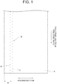
Fig. 1 is a diagram for explaining a configuration of a film according to an embodiment of the invention. -
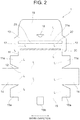
Fig. 2 is a development view of a film storage container according to the embodiment of the invention. -
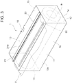
Fig. 3 is a perspective view of a film storage body according to the embodiment of the invention. -
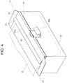
Fig. 4 is a diagram for explaining a protruding piece of the film storage container according to the embodiment of the invention. -
Fig. 5 is a diagram for explaining a modification example of the protruding piece of the film storage container according to the embodiment of the invention. -
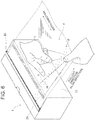
Fig. 6 is a diagram for explaining a method of using the film storage body according to the embodiment of the invention. -
Fig. 7 is a diagram for explaining a configuration of a film according to another embodiment of the invention. -
Fig. 8 is a diagram for explaining a configuration of a film according to still another embodiment of the invention. -
Fig. 9 is a diagram for explaining a configuration of a container main body of a film storage body according to still another embodiment of the invention. -
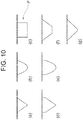
Fig. 10 is a diagram for explaining a configuration of a protrusion of a container main body of a film storage body according to still another embodiment of the invention. -
Fig. 11 is a diagram for explaining a configuration of a film storage body according to still another embodiment of the invention. -
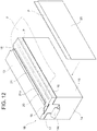
Fig. 12 is a diagram for explaining a configuration of a film storage body according to still another embodiment of the invention. - Hereinafter, embodiments of the invention will be described with reference to the drawings. The following embodiments are just preferable examples, and not intended to limit the application scope of the invention.
- First, using
Fig. 1 , a configuration of a film F according to an embodiment will be described. The film F extends in a predetermined flow direction, and has a cutting-starting point part S provided in a part other than an end part in a width direction that is substantially orthogonal to the flow direction. The film F is torn in the width direction in a case where a cutting force is applied thereto from the cutting-starting point part S as a starting point. - The cutting-starting point part S is a weaker part than a part therearound, and thus serves as a starting point of cutting. In this embodiment, as illustrated in
Fig. 1 , a cutting-starting point part S having a predetermined width is formed by continuously forming perforations (through-holes) H in the flow direction near an end part in the width direction of the film F. In a case where the cutting-starting point part S is disposed near the end part in the width direction of the film F as described above, the cutting-starting point part S is more likely to be in contact with a container, and thus it is possible to reduce an influence on drying of the content (for example, food). In a case where a total length in the width direction of the film F is 30 cm, an interval W between the end part in the width direction of the film F and the (central part of) cutting-starting point part S disposed near the end part in the width direction of the film F is preferably set to 25 mm or greater (for example, 30 to 40 mm) since a through mark is easily formed in the film F by poking the film with a finger. - The perforations H may be formed by cutting with a knife, punching with a heated needle, laser processing, or the like. The width of the cutting-starting point part S is preferably 30 mm or less, and more preferably 10 mm or less. In place of the through-holes, non-through-holes (recessed parts) may be formed.
- As the film F, a wrap film for food packaging that includes a polyolefin-based resin subjected to specific stretching or a specific crosslinking treatment may be employed. The polyolefin-based resin is not particularly limited, and examples thereof include homopolymers of olefins or copolymers of two or more types of olefins such as polyethylene, polypropylene, polybutene, and poly(4-methylpentene), and copolymers of one or more types of olefins and a different type of component other than the olefins. The polyolefin-based resins may be used singly or in combination of two or more types.
- In a case where X-ray scattering is measured, a film F satisfying the following conditions is preferably employed since it is possible to cut the film with high linearity.
- That is, in an azimuthal distribution profile of a scattering intensity at a scattering angle 2θ of 20.9° to 21.8° when X-rays with a wavelength of 0.154 nm are allowed to enter in a normal line direction of the film to measure transmission wide angle X-ray scattering, it is preferable that (i) the azimuthal distribution profile has four scattering peaks, (ii) an interval between neighboring scattering peaks of the four scattering peaks is 90°±10°, (iii) an alignment component ratio R is 0.01 to 100, and (iv) an average area of the four scattering peaks is 1 to 89. The "normal line direction of the film" is a direction perpendicular to a tangential plane at a point in a surface of the film F.
- The transmission wide angle X-ray scattering of the film F may be measured through the following method. First, X-rays with a wavelength of 0.154 nm are allowed to enter in the normal line direction of the film F to measure the transmission wide angle X-ray scattering. In this case, a two-dimensional detector is used. In this measurement, air scattering correction is performed. Next, at a scattering angle (2θ) of 20.9° to 21.8°, a scattering intensity profile is obtained with respect to an azimuth φ. In this case, the scattering intensity is standardized by Formula (1).

- The azimuthal distribution profile preferably has four scattering peaks. Intervals between the four scattering peaks are preferably 90°±10°, more preferably 90°±8°, and even more preferably 90°±5°.
- The four scattering peaks are denoted by A, B, C, and D in ascending order of azimuth, and scattering peak areas thereof are denoted by SA, SB, SC, and SD. In a case where a scattering peak is partially shown near an azimuth of 0°, the sum of areas of scattering peaks partially shown near 0° and 359° is denoted by SA. In this case, an area S of each scattering peak is defined by Formula (2).

- The alignment component ratio R is defined by Formula (3). The alignment component ratio R is preferably 0.01 to 100, more preferably 0.05 to 50, and even more preferably 0.1 to 10.

- An average area S' of the four scattering peaks is defined by Formula (4). The average area S' is preferably 1 to 89, more preferably 10 to 79, and even more preferably 20 to 69.

- The gel fraction in the film F is preferably 10 to 60 wt% since the film is easily cut even with a small force of a finger or the like. The gel fraction is more preferably 15 to 50 wt%, and most preferably 25 to 40 wt%.
- Next, a configuration of a
film storage container 1 according to this embodiment will be described usingFigs. 2 to 5 . - The
film storage container 1 according to this embodiment is provided with a containermain body 10 that has astorage space 10a for storing a film roll R (Fig. 3 ) formed by winding a film F therein, a pull-outopening 20 that is formed in the containermain body 10, and atemporary holding part 30 that temporarily holds the film F pulled to the outside of the containermain body 10 from the pull-outopening 20. As described above, the film F of the film roll R stored in thefilm storage container 1 is configured such that in a case where a cutting force is applied from a cutting-starting point part S as a starting point, the film is torn in a width direction (Fig. 6 ) that is substantially orthogonal to a direction of the pulling from the pull-out opening 20 (flow direction), and cuts are not formed at an end part in the width direction. A film storage body according to this embodiment includes the containermain body 10 of thefilm storage container 1 and the film roll R. - The container
main body 10 has afront plate 11, abottom plate 12, atop plate 13, a pair ofside plates 14, and arear plate 15, and is formed in a substantially rectangular parallelepiped shape. As illustrated inFig. 2 , to both end parts of thefront plate 11 in the width direction and both end parts of therear plate 15 in the width direction,paste margin parts side plates 14. As illustrated inFig. 2 , thetop plate 13, thefront plate 11, thebottom plate 12, and therear plate 15 are connected in this order. - To an end part of the
top plate 13 on a side opposite to thefront plate 11, arear inserting piece 16 is connected that is inserted to overlap with an inner surface of therear plate 15. In addition, to both end parts of thetop plate 13 in the width direction,side inserting pieces 17 are connected that are inserted to overlap with the inner surfaces of theside plates 14. Acut part 18 into which a protrudingpiece 15b provided in therear plate 15 is inserted is formed in a substantially central part in the width direction of a border line L between thetop plate 13 and the rear insertingpiece 16. - Mountain folding is performed along the respective border lines L illustrated by broken lines in
Fig. 2 , and thepaste margin parts front plate 11 and therear plate 15 are pasted on the inner surfaces of theside plates 14 to form a main body part. The rear insertingpiece 16 and theside inserting pieces 17 are inserted into a space inside the main body part to overlap with the inner surfaces of therear plate 15 and theside plates 14, and the protrudingpiece 15b is inserted into thecut part 18 as illustrated inFig. 4 to form the container main body 10 (Fig. 3 ) having a substantially rectangular parallelepiped shape. The protrudingpiece 15b and thecut part 18 form a mechanism for preventing rise of thetop plate 13 from the main body part when the film F is pulled from the pull-outopening 20, and also preventing sinking of thetop plate 13 associated with the use for a long period of time. In this embodiment, the containermain body 10 is not provided with a protrusion for assisting the cutting of the film F of the film roll R. - In this embodiment, an example has been shown in which one cut
part 18 is provided in a substantially central part in the width direction of the border line L between thetop plate 13 and the rear insertingpiece 16, and the protrudingpiece 15b corresponding thereto is provided in therear plate 15. However, the positions and numbers of the cut part and the protruding piece are not limited thereto. For example, as illustrated inFig. 5 , cutparts 18 may be provided at border lines between atop plate 13 and a pair ofside inserting pieces 17, respectively, and protrudingpieces 14a corresponding thereto may be provided inside plates 14, respectively. - The material of the container
main body 10 is not particularly limited, and examples thereof include plastic, metal, wood, cardboard, paperboard, and combinations thereof. Among these, a cardboard having a thickness of 2 to 3 mm is preferably employed since it is possible to secure rigidity and strength even in a case where the containermain body 10 has a relatively large size. - The pull-out
opening 20 is formed to pull the film F of the film roll R stored in thestorage space 10a of the containermain body 10 to the outside of the containermain body 10. In this embodiment, the pull-outopening 20 is formed to extend in the width direction in one (top plate 13) of the six surfaces of the containermain body 10. In this embodiment, a belt-like bending part 21 that bends with abending line 21 a as a center as illustrated inFig. 3 is formed by making a cut in thetop plate 13 of the containermain body 10, and the pull-outopening 20 is opened by bending the bendingpart 21 upward. - The
temporary holding part 30 makes an adhesive force act on the film F pulled to the outside of the containermain body 10 from the pull-outopening 20 to temporarily hold the film F. In this embodiment, as illustrated inFigs. 2 and3 , thetemporary holding part 30 is formed to extend in the width direction near the pull-outopening 20 on one surface (top plate 13) of the containermain body 10. In this embodiment, thetemporary holding part 30 is an adhesive part that makes an adhesive force act on the film F pulled to the outside of the containermain body 10 from the pull-outopening 20. - The adhesive part (temporary holding part 30) may be a part that makes an adhesive force act on the film F. For example, the adhesive part may be formed of a varnish coating layer formed by applying and drying crosslinkable curing varnish. As the crosslinkable curing varnish, for example, ultraviolet (UV) curing varnish may be employed. The type of the UV curing varnish is not particularly limited, and for example, a radical polymerization type, an addition polymerization type, a cationic polymerization type, or the like may be employed. In addition, the adhesive part may be formed using various adhesives such as acrylic adhesives and urethane-based adhesives (for example, a UV-crosslinking curable acrylic ester resin). One surface of a belt-like double-faced tape may be adhered to the
top plate 13 of the containermain body 10 to allow the other surface of the double-faced tape to function as the adhesive part. A friction part that makes a frictional force act on the film F may be employed as thetemporary holding part 30. The friction part may be formed of, for example, a rubber material. - Next, a method of using the
film storage container 1 according to an embodiment of the invention (a method of cutting the film F) will be described usingFig. 6 . - First, a user grips an end part in a pull-out direction of the film F of the film roll R stored in the
storage space 10a of the containermain body 10 of thefilm storage container 1 by hand, pulls a predetermined length of the film from the pull-outopening 20 formed in one surface (top plate 13) of the containermain body 10, and makes an adhesive force act on a lower surface of the pulled film F by thetemporary holding part 30 as illustrated inFig. 6 to temporarily hold the film F. Accordingly, it is possible to temporarily suppress the pulling-out of the film F from the pull-outopening 20. - Next, in a state in which tension is applied to the film F by one hand, the user pokes a part of the cutting-starting point part S on a downstream side of the part on which the adhesive force acts in the film F with a finger of the other hand as illustrated in
Fig. 6 , to form a through mark. Accordingly, the film F is torn in the width direction from the through mark as a starting point. - In a case where a film having cuts at an end part in a width direction is employed, the film may be cut from the cuts as a starting point at the end part in the width direction when tension is applied thereto during the pulling-out of the film from the pull-out
opening 20 or the temporary holding by thetemporary holding part 30. In this embodiment, the film F is not cut from the cuts as a starting point at the end part in the width direction even when pull-out or temporary holding tension is applied thereto. In addition, in a case where a film having cuts at an end part in a width direction is employed, the film may be cut only from a place where the cuts are formed, and thus the amount of the film may not be freely determined. However, in this embodiment, the film F has advantages in that it is possible to freely determine a place where the film is to be torn (a location where a through mark is to be formed), and therefore it is possible to freely determine the amount of the film F. - In the above-described
film storage container 1 according to the embodiment, it is possible to temporarily hold the film F pulled to the outside of the containermain body 10 from the pull-outopening 20 by making an adhesive force act on the film F by the temporary holding part 30 (the pulling-out of the film F from the pull-outopening 20 is temporarily suppressed). In that state, by applying a tearing force to a part on a downstream side of the part on which the adhesive force acts in the film F, it is possible to tear the film F in the width direction. Accordingly, it is possible to tear the film F in the width direction by hand without using a blade or a sliding cutter for cutting the film F. Therefore, thefilm storage container 1 is handled extremely safely, and it is possible to eliminate the burden of sorting in a case where the container is disposed of as waste, and reduce the effort and cost of manufacture of the container. - In the above-described
film storage container 1 according to the embodiment, near the pull-outopening 20, it is possible to make an adhesive force act on the film F pulled from the pull-outopening 20 formed in one surface (top plate 13) of the substantially rectangular parallelepiped-shaped containermain body 10. Accordingly, it is possible to apply a tearing force to the film F in a state in which the pull-out direction is not shifted without loosening or distortion, and thus it is possible to clearly tear the film F. - In the above-described
film storage container 1 according to the embodiment, in a case where the film F is pulled from the pull-outopening 20 formed in thetop plate 13 of the containermain body 10, it is possible to fix thetop plate 13 to the main body part (formed by thefront plate 11, thebottom plate 12, theside plates 14, and the rear plate 15). Accordingly, it is possible to prevent rise of thetop plate 13 when the film F is pulled, and prevent sinking of thetop plate 13 associated with the use for a long period of time. In addition, even in a case where the adhesive force acting on the film F by thetemporary holding part 30 is relatively large, it is possible to prevent rise of thetop plate 13. Therefore, since it is possible to employ atemporary holding part 30 having high adhesive strength, it is possible to clearly tear the film F by more securely bringing thetemporary holding part 30 into close contact with the film F. In addition, it is possible to avoid a situation in which the adhesive force of thetemporary holding part 30 is reduced and the film is not easily torn in a case where the container is repeatedly used. - In the above-described film F according to the embodiment, since the cutting-starting point part S is formed in a part other than an end part in a width direction (near the end part), it is possible to easily cut the film by hand. In order to cut a film having a cutting-starting point part formed at an end part in a width direction by hand, it is necessary to greatly twist a wrist (that is, a large motion is required for cutting). However, the film F having the cutting-starting point part S in a part other than an end part in a width direction as in this embodiment can be cut with a relatively small motion. In addition, in a case where a cutting-starting point part is formed at an end part in a width direction of a film, an unexpected situation may occur such as cutting of the film from the end part in the width direction when tension is applied to the film. However, in a case where the cutting-starting point part S is formed in a part other than the end part in the width direction of the film F as in this embodiment, it is possible to prevent the occurrence of such a situation. In addition, in a case where a cutting-starting point part is formed at an end part in a width direction of a film, the end part in the width direction of the film may deform and may not function as a cutting-starting point part when tension is applied thereto. However, in a case where the cutting-starting point part S is formed in a part other than the end part in the width direction of the film F as in this embodiment, it is possible to stably start the cutting due to little deformation of the cutting-starting point part S even when tension is applied.
- In the above-described embodiments, an example has been shown in which the cutting-starting point part S is formed by forming the perforations (through-holes) H. However, the configuration of the cutting-starting point part is not limited thereto. For example, as illustrated in
Fig. 7 , a cutting-starting point part S having a predetermined width may be formed by continuously performing embossing in a flow direction near an end part in a width direction of a film F. In a case where the cutting-starting point part S has a non-through structure as described above, it is possible to prevent a product (for example, food) that is covered with the film F from being dried. - In addition, scratches may be randomly generated in place of embossing. In this case, the depth of a scratch is preferably set to approximately 1 % to 50% of the thickness of the film F. In addition, a part that becomes weak by scraping with a file-like object may serve as a cutting-starting point part. Furthermore, by performing a chemical treatment or mechanical processing, a belt-like part that has a predetermined width and a set thickness and is thinner than the periphery thereof may be formed near the end part in the width direction of the film F, and this thin belt-like part may be allowed to serve as a cutting-starting point part.
- In the above-described embodiments, an example has been shown in which the cutting-starting point part S is formed near the end part in the width direction of the film F, but a plurality of lines of cutting-starting point parts S (for example, three lines as illustrated in
Fig. 8 ) may be formed. - In the above-described embodiments, an example has been shown in which the
temporary holding part 30 is formed to temporarily hold the film F, in place of a protrusion for assisting the cutting of the film F in the containermain body 10. However, the configuration of the containermain body 10 is not limited thereto. - For example, as illustrated in
Fig. 9 , a containermain body 10A having a rectangular parallelepiped-shapedstorage chamber 20A with an opened upper part and alid body 30A that covers thestorage chamber 20A may be employed. Thestorage chamber 20A may be formed by wall surfaces including afront plate 21 A, abottom plate 22A, arear plate 23A, andside plates 24A. Thelid body 30A may be formed by wall surfaces including alid plate 31 A that is provided to be connected in such a direction as to cover thestorage chamber 20A from an upper edge of therear plate 23A, a coveringlid piece 32A that extends in such a direction as to cover thefront plate 21 A from a front edge of thelid plate 31 A, and side coveringlid pieces 33A that are provided on both sides of the coveringlid piece 32A. The containermain body 10A may be provided with a protrusion for assisting the cutting of the film F of the film roll R in place of thetemporary holding part 30. - The material of the container
main body 10A is not particularly limited, and examples thereof include plastic, metal, wood, cardboard, paperboard, and combinations thereof. Among these, a paperboard is preferable in view of ease of use. This paperboard has a thickness of 0.35 to 1.50 mm, and in general, the larger the thickness, the higher the rigidity, strength, and solidity of the containermain body 10A. The thickness is more preferably 0.35 to 0.80 mm since bending processing is easily performed. - Examples of the shape of a protrusion P are illustrated in
Figs. 10(a) to 10(g) . A position where the protrusion P is to be attached is not particularly limited as long as it is possible to easily cut the film F. For example, the protrusion may be provided at a tip edge part of the coveringlid piece 32A of thelid body 30A. The material of the protrusion P is not particularly limited, and examples thereof include ester-based polymers such as aromatic ester polymers and aliphatic ester polymers such as lactic acid-based polymers, polymeric materials such as ethylene-based polymers, propylene-based polymers, styrene-based polymers, and amide-based polymers, vulcanized paper, resin-impregnated hard paper, abrasive grains, abrasive grain fixing paper, and tin. Among these, lactic acid-based polymers are more preferable since these are of a circulating type and are eco-friendly. - In addition, the film storage container may be provided with both of the
temporary holding part 30 and the protrusion P for assisting the cutting of the film F of the film roll R. For example, afilm storage container 1 A obtained by slightly deforming thefilm storage container 1 illustrated inFigs. 3 and4 (the pull-outopening 20 faces the protrudingpiece 15b, and thetemporary holding part 30 is moved toward the protrudingpiece 15b: seeFig. 11 ) may be employed, and a protrusion P may be disposed at two places on the left and right of the protrudingpiece 15b. A tin saw blade having a length of approximately 2 to 4 cm may be employed as the protrusion P. For example, as illustrated inFig. 11 , a protrusion P may be disposed at two places on the left and right of the protrudingpiece 15b in a manner such that the protrusion P is fixed to two places on left and right sides in an upper end part ofthick paper 40 having acutout part 41 formed by cutting out a part corresponding to the protrudingpiece 15b, and thethick paper 40 is inserted into thefilm storage container 1A (between theplate 15 and the inserting piece 16). - In addition, as illustrated in
Fig. 12 , afilm storage container 1 B may be employed in which cutparts 18 are provided at border lines between atop plate 13 and a pair ofside inserting pieces 17, respectively, and protrudingpieces 14a corresponding thereto are provided inside plates 14, respectively. In such a case, as illustrated inFig. 12 , a protrusion P (for example, a tin saw blade) may be disposed over the entire width of an upper end part of aplate 15. In this case, as illustrated inFig. 12 , the protrusion P may be disposed over the entire width of the upper end part of theplate 15 in a manner such that the protrusion P is fixed to an upper end part ofthick paper 50 having substantially the same shape as theplate 15, and thethick paper 50 is inserted into thefilm storage container 1 B (between theplate 15 and the inserting piece 16). - In the above-described embodiments, an example has been shown in which the invention is applied to a wrap film for food packaging, but the invention may be applied to films for other use (for example, films for medical use, agricultural use, or packing use). In a case where the invention is applied to films for the above-described three examples, the container main body 10 (10A) for storing the film roll R may be omitted.
- The invention is not limited to the above-described embodiments, and appropriate modifications of the embodiments in design made by a person skilled in the art are also included in the scope of the invention as long as these have the characteristics of the invention. That is, the respective elements of the embodiments, and positions, materials, conditions, shapes, sizes, and the like thereof are not limited to the examples and may be appropriately modified. In addition, the respective elements of the embodiments may be combined as long as the combination is technically possible, and combinations of the elements are also included in the scope of the invention as long as these have the characteristics of the invention. Reference Signs List
-
- 1, 1A, 1B: FILM STORAGE CONTAINER
- 10, 10A: CONTAINER MAIN BODY
- 10a: STORAGE SPACE
- 11: FRONT PLATE
- 12: BOTTOM PLATE
- 13: TOP PLATE (ONE SURFACE OF CONTAINER MAIN BODY)
- 14: SIDE PLATE
- 14a: PROTRUDING PIECE
- 15: REAR PLATE
- 15b: PROTRUDING PIECE
- 16: REAR INSERTING PIECE
- 18: CUT PART
- 20: PULL-OUT OPENING
- 20A: STORAGE CHAMBER
- 21 A: FRONT PLATE
- 22A: BOTTOM PLATE
- 23A: REAR PLATE
- 24A: SIDE PLATE
- 30: TEMPORARY HOLDING PART
- 30A: LID BODY
- 31 A: LID PLATE
- 32A: COVERING LID PIECE
- 33A: SIDE COVERING LID PIECE
- F: FILM
- H: PERFORATION
- P: PROTRUSION
- R: FILM ROLL
- S: CUTTING-STARTING POINT PART
Claims (20)
- A film storage container comprising:a container main body that has a storage space for storing a film roll therein;
anda pull-out opening that is formed in the container main body in order to pull a film of the roll stored in the storage space to the outside of the container main body,wherein the film is torn in a width direction that is substantially orthogonal to a direction of the pulling from the pull-out opening in a case where a tearing force is applied thereto,the container main body has a top plate, a front plate, a bottom plate, a pair of side plates, and a rear plate,a protruding piece for fixing the top plate is inserted into a space inside a main body part formed by the front plate, the bottom plate, the side plates, and the rear plate, andthe pull-out opening is formed in the top plate. - The film storage container according to claim 1, wherein:the container main body is formed in a substantially rectangular parallelepiped shape,the pull-out opening is formed to extend in the width direction in one of the six surfaces of the container main body,a temporary holding part is provided to make an adhesive force or a frictional force act on the film pulled to the outside of the container main body from the pull-out opening so as to temporarily hold the film, andthe temporary holding part is formed to extend in the width direction near the pull-out opening in the one surface of the container main body.
- The film storage container according to claim 2, wherein a cut part is formed in the top plate, and the protruding piece is inserted into the cut part.
- The film storage container according to claim 2 or 3, wherein the temporary holding part is an adhesive part that makes an adhesive force act on the film pulled to the outside of the container main body from the pull-out opening.
- The film storage container according to claim 4, wherein the adhesive part is formed of a varnish coating layer.
- The film storage container according to claim 4, wherein the adhesive part is formed of a double-faced tape.
- The film storage container according to claim 2 or 3, wherein the temporary holding part is a friction part that makes a frictional force act on the film pulled to the outside of the container main body from the pull-out opening.
- The film storage container according to claim 7, wherein the friction part is formed of a rubber material.
- A film comprising a cutting-starting point part that extends in a predetermined flow direction and is provided in a part other than an end part in a width direction that is substantially orthogonal to the flow direction.
- The film according to claim 9, wherein gel fraction is 10 to 60 wt%.
- The film according to claim 9 or 10, wherein the cutting-starting point part is at least one perforation.
- The film according to claim 9 or 10, wherein the cutting-starting point part is a part subjected to embossing.
- The film according to any one of claims 9 to 12, wherein the cutting-starting point part is continuously formed in the flow direction.
- The film according to any one of claims 9 to 13,wherein the cutting-starting point part is formed inside the end part in the width direction by 25 mm or greater.
- The film according to any one of claims 9 to 13,wherein the cutting-starting point part is formed in a substantially central part in the width direction.
- A film roll that is formed by winding the film according to any one of claims 9 to 15.
- A film storage body comprising:the film roll according to claim 16; anda container main body that has a storage space for storing the film roll therein,wherein the container main body has a protrusion for assisting the cutting of the film of the film roll.
- The film storage body according to claim 17,
wherein the container main body has: a rectangular parallelepiped-shaped storage chamber with an opened upper part that is formed by wall surfaces including a front plate, a bottom plate, a rear plate, and side plates; and a lid body that is formed by wall surfaces including a lid plate that is provided to be connected in such a direction as to cover the storage chamber from an upper edge of the rear plate, a covering lid piece that extends in such a direction as to cover the front plate from a front edge of the lid plate, and side covering lid pieces that are provided on both sides of the covering lid piece, and
the protrusion is provided at a tip edge part of the covering lid piece. - A film storage body comprising:the film roll according to claim 16; anda container main body that has a storage space for storing the film roll therein,wherein the container main body does not have a protrusion for assisting the cutting of the film of the film roll.
- A film cutting method comprising:forming a through mark by poking a part of the cutting-starting point part of the film according to any one of claims 9 to 15 with a finger; andtearing the film in the width direction from the through mark as a starting point.
Applications Claiming Priority (3)
| Application Number | Priority Date | Filing Date | Title |
|---|---|---|---|
| JP2015099818 | 2015-05-15 | ||
| JP2015117652 | 2015-06-10 | ||
| PCT/JP2016/064291 WO2016186026A1 (en) | 2015-05-15 | 2016-05-13 | Film storage container, film, film roll, and film storage body |
Publications (2)
| Publication Number | Publication Date |
|---|---|
| EP3296221A1 true EP3296221A1 (en) | 2018-03-21 |
| EP3296221A4 EP3296221A4 (en) | 2018-10-31 |
Family
ID=57320019
Family Applications (1)
| Application Number | Title | Priority Date | Filing Date |
|---|---|---|---|
| EP16796419.6A Withdrawn EP3296221A4 (en) | 2015-05-15 | 2016-05-13 | Film storage container, film, film roll, and film storage body |
Country Status (5)
| Country | Link |
|---|---|
| US (1) | US20180134484A1 (en) |
| EP (1) | EP3296221A4 (en) |
| JP (1) | JPWO2016186026A1 (en) |
| CN (1) | CN107531364A (en) |
| WO (1) | WO2016186026A1 (en) |
Families Citing this family (1)
| Publication number | Priority date | Publication date | Assignee | Title |
|---|---|---|---|---|
| US12344496B2 (en) * | 2021-08-26 | 2025-07-01 | Reynolds Consumer Products LLC | Containers, blanks, and methods for dispensing web material |
Family Cites Families (16)
| Publication number | Priority date | Publication date | Assignee | Title |
|---|---|---|---|---|
| US3974947A (en) * | 1973-06-13 | 1976-08-17 | The Dow Chemical Company | Dispensing carton for roll materials |
| US4179030A (en) * | 1978-11-24 | 1979-12-18 | Eltra Corporation | Unitary foldable dispenser reel and container with removable dispenser portion |
| JPS591948Y2 (en) * | 1979-12-19 | 1984-01-19 | 三郎 桜井 | Wrap film case |
| JPS6140317U (en) * | 1984-08-16 | 1986-03-14 | 株式会社 日本エンジニアリングサ−ビス | Paper box containing rolled continuous bags |
| US4651911A (en) * | 1986-03-10 | 1987-03-24 | Reynolds Metals Company | Roll material dispenser carton |
| JP2650849B2 (en) * | 1994-03-25 | 1997-09-10 | 清二 加川 | Easy tearable laminated film and method for producing the same |
| JPH11124133A (en) * | 1997-10-21 | 1999-05-11 | Asahi Chem Ind Co Ltd | Wrapping film storing box |
| JP2001246707A (en) * | 2000-03-06 | 2001-09-11 | Asahi Kasei Corp | Crosslinked laminated wrap film |
| US6682808B2 (en) * | 2001-04-20 | 2004-01-27 | Asahi Kasei Kabushiki Kaisha | Crosslinked laminated wrap film and dispenser box therefor |
| ITTO20010110U1 (en) * | 2001-06-29 | 2002-12-30 | Nuova Poliver Di Oddone Colomb | PERFECTED FILM OF SYNTHETIC MATERIAL, PARTICULARLY FOR THE PACKAGING OF FOOD PRODUCTS. |
| US20050139626A1 (en) * | 2003-04-04 | 2005-06-30 | Owens John R. | Newsprint dispensing device |
| JP4824402B2 (en) * | 2005-12-28 | 2011-11-30 | 大王製紙株式会社 | Roll sheet storage body and storage body integrated roll sheet |
| CN200942946Y (en) * | 2006-08-09 | 2007-09-05 | 詹万均 | Improvement of box body structure to prevent fresh-keeping film from rewinding |
| CN201037067Y (en) * | 2006-12-17 | 2008-03-19 | 谢伟森 | Integrated structure of preservative film packaging box |
| JP6158529B2 (en) * | 2012-05-28 | 2017-07-05 | 株式会社クレハ | Packaging container |
| CN203512918U (en) * | 2013-09-25 | 2014-04-02 | 郭家庆 | Sliding-knife cutting type preservative film box with anti-sliding strips |
-
2016
- 2016-05-13 WO PCT/JP2016/064291 patent/WO2016186026A1/en not_active Ceased
- 2016-05-13 CN CN201680024409.4A patent/CN107531364A/en active Pending
- 2016-05-13 JP JP2017519181A patent/JPWO2016186026A1/en active Pending
- 2016-05-13 EP EP16796419.6A patent/EP3296221A4/en not_active Withdrawn
- 2016-05-13 US US15/572,911 patent/US20180134484A1/en not_active Abandoned
Also Published As
| Publication number | Publication date |
|---|---|
| EP3296221A4 (en) | 2018-10-31 |
| US20180134484A1 (en) | 2018-05-17 |
| CN107531364A (en) | 2018-01-02 |
| JPWO2016186026A1 (en) | 2017-11-16 |
| WO2016186026A1 (en) | 2016-11-24 |
Similar Documents
| Publication | Publication Date | Title |
|---|---|---|
| JP2017145063A (en) | Packaging container | |
| JP6271783B2 (en) | Winding body storage box and storage box with winding body | |
| US20180134484A1 (en) | Film storage container, film, film roll, and film storage body | |
| JP7253393B2 (en) | Cosmetic box for packaging roll | |
| JP6277000B2 (en) | Winding body storage box and storage box with winding body | |
| JP6125922B2 (en) | Wrap film equipment | |
| JP2018122877A (en) | Packaging box for wound body and manufacturing method of the same | |
| JP2009292508A (en) | Wrap film storage box | |
| KR101551155B1 (en) | Case having a function of Cutting Wrapping Materials | |
| CA2375280A1 (en) | Tape dispenser | |
| GB2502391A (en) | Re-closable container with lid and tray with stiffening member | |
| TWI292381B (en) | Package for a roll of foil | |
| JP5584593B2 (en) | Packaging medium storage container and packaging medium supply tool | |
| EP2030911B1 (en) | Easy-opening packaging for folded and stacked sheet-like articles | |
| JP3195468B2 (en) | Wrap film storage box | |
| JP2015182816A (en) | Wound body storage box and storage box including wound body | |
| JP6120584B2 (en) | Winding film storage box | |
| JP2010042843A (en) | Accessory device for storage box | |
| JP6715287B2 (en) | Storage box and carton | |
| JPH05262350A (en) | Cutting tool for container for wound film | |
| US10800632B1 (en) | Tape cutting inserts | |
| JP2008239155A (en) | Filmless carton with sanitary paper | |
| JP7253392B2 (en) | Cosmetic box for packaging roll | |
| JP2015034046A (en) | Wrap film storage box | |
| JP5658554B2 (en) | Packaging media storage container |
Legal Events
| Date | Code | Title | Description |
|---|---|---|---|
| STAA | Information on the status of an ep patent application or granted ep patent |
Free format text: STATUS: THE INTERNATIONAL PUBLICATION HAS BEEN MADE |
|
| PUAI | Public reference made under article 153(3) epc to a published international application that has entered the european phase |
Free format text: ORIGINAL CODE: 0009012 |
|
| STAA | Information on the status of an ep patent application or granted ep patent |
Free format text: STATUS: REQUEST FOR EXAMINATION WAS MADE |
|
| 17P | Request for examination filed |
Effective date: 20171114 |
|
| AK | Designated contracting states |
Kind code of ref document: A1 Designated state(s): AL AT BE BG CH CY CZ DE DK EE ES FI FR GB GR HR HU IE IS IT LI LT LU LV MC MK MT NL NO PL PT RO RS SE SI SK SM TR |
|
| AX | Request for extension of the european patent |
Extension state: BA ME |
|
| RIC1 | Information provided on ipc code assigned before grant |
Ipc: B65D 5/72 20060101ALI20180509BHEP Ipc: B65D 25/52 20060101AFI20180509BHEP Ipc: B65D 85/671 20060101ALI20180509BHEP |
|
| DAV | Request for validation of the european patent (deleted) | ||
| DAX | Request for extension of the european patent (deleted) | ||
| A4 | Supplementary search report drawn up and despatched |
Effective date: 20180927 |
|
| RIC1 | Information provided on ipc code assigned before grant |
Ipc: B65D 85/672 20060101ALI20180922BHEP Ipc: B65D 5/72 20060101ALI20180922BHEP Ipc: B65D 25/52 20060101AFI20180922BHEP Ipc: B65D 85/671 20060101ALI20180922BHEP Ipc: B65D 83/08 20060101ALI20180922BHEP |
|
| STAA | Information on the status of an ep patent application or granted ep patent |
Free format text: STATUS: EXAMINATION IS IN PROGRESS |
|
| 17Q | First examination report despatched |
Effective date: 20181030 |
|
| STAA | Information on the status of an ep patent application or granted ep patent |
Free format text: STATUS: THE APPLICATION IS DEEMED TO BE WITHDRAWN |
|
| 18D | Application deemed to be withdrawn |
Effective date: 20190312 |