EP3296216A1 - Obviating liquid instrusion into a gas supply line - Google Patents
Obviating liquid instrusion into a gas supply line Download PDFInfo
- Publication number
- EP3296216A1 EP3296216A1 EP16202028.3A EP16202028A EP3296216A1 EP 3296216 A1 EP3296216 A1 EP 3296216A1 EP 16202028 A EP16202028 A EP 16202028A EP 3296216 A1 EP3296216 A1 EP 3296216A1
- Authority
- EP
- European Patent Office
- Prior art keywords
- tank
- inlet pipe
- gas
- injection device
- chamber
- Prior art date
- Legal status (The legal status is an assumption and is not a legal conclusion. Google has not performed a legal analysis and makes no representation as to the accuracy of the status listed.)
- Granted
Links
Images



Classifications
-
- F—MECHANICAL ENGINEERING; LIGHTING; HEATING; WEAPONS; BLASTING
- F17—STORING OR DISTRIBUTING GASES OR LIQUIDS
- F17C—VESSELS FOR CONTAINING OR STORING COMPRESSED, LIQUEFIED OR SOLIDIFIED GASES; FIXED-CAPACITY GAS-HOLDERS; FILLING VESSELS WITH, OR DISCHARGING FROM VESSELS, COMPRESSED, LIQUEFIED, OR SOLIDIFIED GASES
- F17C13/00—Details of vessels or of the filling or discharging of vessels
- F17C13/008—Details of vessels or of the filling or discharging of vessels for use under microgravity conditions
-
- B—PERFORMING OPERATIONS; TRANSPORTING
- B64—AIRCRAFT; AVIATION; COSMONAUTICS
- B64G—COSMONAUTICS; VEHICLES OR EQUIPMENT THEREFOR
- B64G1/00—Cosmonautic vehicles
- B64G1/22—Parts of, or equipment specially adapted for fitting in or to, cosmonautic vehicles
- B64G1/40—Arrangements or adaptations of propulsion systems
- B64G1/402—Propellant tanks; Feeding propellants
-
- F—MECHANICAL ENGINEERING; LIGHTING; HEATING; WEAPONS; BLASTING
- F17—STORING OR DISTRIBUTING GASES OR LIQUIDS
- F17C—VESSELS FOR CONTAINING OR STORING COMPRESSED, LIQUEFIED OR SOLIDIFIED GASES; FIXED-CAPACITY GAS-HOLDERS; FILLING VESSELS WITH, OR DISCHARGING FROM VESSELS, COMPRESSED, LIQUEFIED, OR SOLIDIFIED GASES
- F17C2221/00—Handled fluid, in particular type of fluid
- F17C2221/01—Pure fluids
- F17C2221/014—Nitrogen
-
- F—MECHANICAL ENGINEERING; LIGHTING; HEATING; WEAPONS; BLASTING
- F17—STORING OR DISTRIBUTING GASES OR LIQUIDS
- F17C—VESSELS FOR CONTAINING OR STORING COMPRESSED, LIQUEFIED OR SOLIDIFIED GASES; FIXED-CAPACITY GAS-HOLDERS; FILLING VESSELS WITH, OR DISCHARGING FROM VESSELS, COMPRESSED, LIQUEFIED, OR SOLIDIFIED GASES
- F17C2221/00—Handled fluid, in particular type of fluid
- F17C2221/01—Pure fluids
- F17C2221/016—Noble gases (Ar, Kr, Xe)
- F17C2221/017—Helium
-
- F—MECHANICAL ENGINEERING; LIGHTING; HEATING; WEAPONS; BLASTING
- F17—STORING OR DISTRIBUTING GASES OR LIQUIDS
- F17C—VESSELS FOR CONTAINING OR STORING COMPRESSED, LIQUEFIED OR SOLIDIFIED GASES; FIXED-CAPACITY GAS-HOLDERS; FILLING VESSELS WITH, OR DISCHARGING FROM VESSELS, COMPRESSED, LIQUEFIED, OR SOLIDIFIED GASES
- F17C2270/00—Applications
- F17C2270/01—Applications for fluid transport or storage
- F17C2270/0186—Applications for fluid transport or storage in the air or in space
- F17C2270/0194—Applications for fluid transport or storage in the air or in space for use under microgravity conditions, e.g. space
Definitions
- the present invention concerns a gas injection device for injecting an expulsion gas into a tank for a liquid.
- the invention further concerns a tank for a cryogenic or storable fuel and a spacecraft comprising a tank.
- liquids such as cryogenic fuels or storable fuels (i.e., fuels being storable for several years at room temperature) of a spacecraft and/or oxidators may be extracted from a tank by supplying pressurised inert gas such as helium or nitrogen into the tank, which then expulses the respective liquid.
- pressurised inert gas such as helium or nitrogen
- a counter current of the liquid into said line which may occur when the gas injection is interrupted, is to be obviated.
- Such counter current may, in particular, result from an acceleration of the tank carrying apparatus, which may be a spacecraft, for instance.
- document US 40 27 494 A discloses a phase separator involving superconducting magnets. From US 48 48 987 A , a phase separator deploying pumps and valves is known.
- Document US 70 77 885 B2 discloses a phase separator including a propeller and a membrane.
- separator devices known from documents US 44 35 196 A and US 46 17 031 A are limited to operation under gravity conditions.
- Document DE 10 2008 026 320 discloses a device preventing intrusion of a liquid into a gas line, wherein a separation of gas and liquid is achieved by means of meshes including a gas bubble.
- the device being applicable not only when a gas supply into the tank is stopped, but also when gas is discharged from the tank, is rather complex and, therefore, costly in production.
- an object of the present invention to provide a robust and plain technique for protecting a gas supply line against intrusion of a liquid. It is a further object of the present invention to provide a tank for a liquid ensuring a gas supply line protection, and a spacecraft having a protected gas supply line.
- a gas injection device is to inject an expulsion gas into a tank for a liquid.
- the injection device comprises an inlet pipe for receiving the gas and a distributor portion for releasing the gas through a plurality of capillary passages (provided in the distributor portion).
- the inlet pipe has a first end configured to be connected to a gas supply line (e.g. by means of a connector element of a tank), and a second end located within a chamber formed by the distributor portion.
- the capillary passages respectively extend from the chamber in a direction adapted to a periphery of the chamber.
- the capillary passages are arranged so as to allow for a main flow (of gas or liquid) running, through the capillary passages, along a curve basically tangent to the periphery of the chamber; said curve may be straight or crooked.
- a main flow of gas or liquid running, through the capillary passages, along a curve basically tangent to the periphery of the chamber; said curve may be straight or crooked.
- the periphery of the chamber is basically circular.
- the capillary passages (or the main flow they allow for) may be crooked or essentially straight.
- the capillary action of a liquid and the direction of the capillary passages being adapted to the periphery of the chamber (i.e., to the boundary thereof)
- the liquid is forced into a rotational movement.
- the liquid encloses a gas bubble at the second end of the inlet pipe, and the gas bubble is inhibited to escape from the chamber.
- the gas bubble thus blocks the inlet pipe, so that the liquid cannot enter the gas supply line.
- the chamber thus provides a compensation volume in which the size of the gas bubble may vary, rendering tolerable pressure variations which may occur within the gas supply system.
- the gas injection device according to the present invention provides for a reliable protection of a supply line, and due to its clear structure, it is both robust and producible without effort.
- the capillary passages provide the only openings of the chamber towards the environment of the gas injection device within the tank.
- At least one of the capillary passages includes at least a section which widens towards an environment of the distributor portion, thus, in which the cross-sectional area of the capillary passages increases outwards, respectively.
- one or more of the capillary passages may narrow towards the chamber.
- the chamber may be basically shaped rotationally symmetric with respect to an axis; in particular, the periphery of the chamber may extend along the circumferential surface of a circular cylinder.
- at least a portion (especially a portion comprising the second end) of the inlet pipe is arranged basically coaxial with the chamber.
- the distributor portion may preferably include a (preferably circular) base plate, a cover plate through which the inlet pipe passes and a side structure being a structure connecting the base plate and the cover plate.
- the chamber may be determined.
- the base plate and the cover plate face each other.
- the base plate and/or the cover plate may have a basically circular circumference, and/or may be plane, domed or corrugated.
- the cover plate and/or the base plate may comprise a respective frame region surrounding the blades, thus providing an overhang over the blades.
- Such frame region(s) may provide for an advantageous direction of liquid intruding into the distributor portion when the gas injection has been stopped, namely a direction basically parallel to the cover plate an/or the base plate, respectively, thus improving the rotational movement within the chamber.
- a gap between the boundary of the chamber and the gas bubble has a width w in the order of the capillary radius r, which is specified by the boundary surface (i.e., by the mensicus) of the liquid and the gas.
- the capillary radius is the radius of the gas bubble.
- the capillary radius depends on the surface tension and the length scale of the geometry.
- the stability of the meniscus depends on the width of the gap in a monotonically decreasing way. That is, when the gap is narrower (i.e., when the width is smaller), the meniscus is more stable with respect to external disturbances (which may be caused by an increase in speed).
- the emerging width w is based on the stability of the liquid-gas interface which is driven by the acceleration thrust level in orbit. Moreover, the smaller the gas bubble, the larger is the capillary pressure. For instance, said width w may be in an interval from 0.5r to 1.5r (so that 0.5r ⁇ w ⁇ 1.5r), preferably from 0.75r to 1.25r (so that 0.75r ⁇ w ⁇ 1.25r) or even from 0.9r to 1.1r (so that 0.9r ⁇ w ⁇ 1.1r). Such relations advantageously prevent the escape of gas and the intrusion of liquid into the pipe.
- the side structure may comprise a plurality of capillary tubes forming the capillary passages.
- the capillary tubes may be basically tangent to the periphery of the chamber (i.e., they may respectively share a same tangent line with said periphery).
- the side structure may include a plurality of blades extending from the base plate to the cover plate. The plurality of blades may be shifted in position from one to another, thereby surrounding the chamber in a fan-like manner. Preferably, some or all of the blades extend in a direction orthogonal to the base plate and/or to the cover.
- some or all of the blades may extend basically tangentially to the periphery of the chamber.
- the blades may have respective edges arranged along a circumferential surface of a circular cylinder which may form the periphery of the chamber, and the blades may extend along respective tangent planes of the circumferential surface.
- Gaps between neighbouring blades may form the capillary passages.
- Such structure of the device is particularly stable and simple in production.
- the plurality of blades may include a subset of blades that are fixed (e.g., cast or welded) to the base plate, these blades further referred to herein as base blades.
- Some or all of such base blades may be configured as fastening blades, by comprising fastening means (e.g. a flange, a bore or the like) for fastening the respective base blade to the cover plate, possibly by means of a further fastening means (such as a clamp or a bolt), so as to build the distributor portion.
- the plurality of blades may include a subset of blades that are fixed (e.g., cast or welded) to the cover plate, these blades further referred to herein as cover blades.
- cover blades may be configured as fastening blades, by comprising fastening means (e.g. a flange, a bore or the like) for fastening the respective cover blade to the base plate, possibly by means of a further fastening means (such as a clamp or a bolt), so as to build the distributor portion.
- fastening means e.g. a flange, a bore or the like
- a further fastening means such as a clamp or a bolt
- Such embodiments provide a robust distributor portion and a simple construction thereof.
- base blades and cover blades alternately, narrow capillary passages can be formed, whereas due to the greater distance of the base blades to one another, they can be easily fixed to the base plate, and analogously, the cover blades can be easily fixed to the cover plate.
- the distributor portion or even the entire gas injection device may be monolithic, formed e.g. in an additive manufacturing process.
- the inlet pipe comprises a cylinder-like portion in which the inlet pipe is basically shaped as a circular cylinder.
- the first end of the inlet pipe may be an end of such cylinder-like portion.
- the inlet pipe comprises a narrowing portion in which the inlet pipe narrows towards the second end.
- the narrowing portion may be shaped basically conically or along an arched surface of revolution narrowing towards the second end.
- the portion may be shaped essentially as a truncated cone or as a truncated ellipsoid or a truncated hyperboloid.
- Such shapes support that, even in phases of small increase in speed (which phases are common in orbit mode), a gas bubble may be kept at the second end by the capillary pressure of entering liquid when the gas supply has been stopped (possibly temporarily).
- said shape may minimise the pressure loss in phases when gas supply into the tank is restarted and the capillary passages are being blown free from liquid.
- the pressure loss may be driven by a high number of capillary passages (e.g., 12 or more) which may add up to a large cross sectional area.
- the narrowing portion at least partially extends into the interior of the chamber in the distributor portion.
- the second end may preferably be placed in a central region of the chamber.
- the (perpendicular) distance of the second end to a base plate of the distributor portion may be in an interval extending from one third to two thirds of the whole distance of the base plate to a cover plate of the distributor portion, especially at essentially half distance between the base plate and the cover.
- the second end of the pipe is formed as a plain (preferably smooth) circumferential edge. That is, preferably no spikes or other irregularities are provided at the end edge of the inlet pipe.
- a plain (preferably smooth) circumferential edge Such structure improves the stability of a gas bubble formed due to the rotational movement of entering liquid when the gas injection has been stopped.
- the wall of the inlet pipe may be radially tapered at the second end of the inlet pipe, so that a sharp edge is formed at said second end. Such shape improves the second end holding the gas bubble in the situation mentioned.
- a tank according to the present invention is configured to contain and provide a liquid, such as a cryogenic fuel (for example, liquid hydrogen and/or liquid oxygen) or a storable fuel (e.g., monomethylhydrazine and/or hydrazine).
- the tank (which is preferably configured to be used in space, in particular in zero gravity condition) comprises a gas injection device according to an embodiment of the present invention as disclosed in this document.
- the first end of the inlet pipe is connected (directly or with one or more further components in between) to a connector element of the tank, the connector element being configured to be joined to a gas supply line.
- the connector element may be formed by an intake tube extending into a tank volume, and the first end may be imposed onto or inserted into the intake tube.
- intake tube may be fixed to a wall of the tank or it may be formed monolithically with the tank wall.
- a gap between the intake tube and the inlet pipe has a width (in a radial direction) of at most 0.2mm.
- the inlet pipe and the intake tube each may comprise respective flanges which may be detachable or permanently connected to each other, e.g. by one or more bolts or by welding.
- the distributor portion of the gas injection device is located within the tank volume.
- a spacecraft according to the present invention comprises a tank according to an embodiment of the present invention, and a gas supply line connected to the tank.
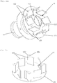
- FIG 1 provides a perspective illustration of a gas injection device 10 according to an exemplary embodiment of the present invention.
- the gas injection device 1 comprises an inlet pipe 11 having a first end 111 to be connected to a gas supply line.
- the first end may be configured to be inserted into an intake tube of a tank, as shown in Figure 3 and described below with reference thereto, or it may be configured to be imposed onto an intake tube of a tank.
- the exemplary gas injection device 10 shown in Figure 1 comprises a flange 14 surrounding the inlet pipe 11.
- the flange may preferably be configured to be fixed to a connector element of a tank.
- Such connector element which may be formed monolithically with at least a portion of a wall of the tank or which may be connected to the wall of the tank, may likewise comprise a respective flange.
- the connector element may include an intake tube of a tank as mentioned above.
- Holes 141 in the flange 14 of the gas injection device 10 may serve in combination with respective bolts (not shown) to fix the gas injection device 10 to the (not shown) connector element of the tank.
- the second end 112 of the inlet pipe 11 is formed as a plain circumferential edge and is arranged in a chamber 15 formed within a distributor portion 12 of the gas injection device 10. Due to the perspective, neither the second end nor the chamber 15 is visible in Figure 1 ; they are, however, indicated in Figures 2a, 2b and 3 .
- the distributor portion 12 builds a plurality of capillary passages 13 which are configured to release an expulsion gas injected into the inlet pipe 11 and guided therewith into the chamber.
- the capillary passages extend in a direction adapted to a periphery of the chamber 15, and they narrow from the periphery of the distributor portion 12 towards the chamber in the interior of the distributor portion 12.
- the capillary passages are essentially straight, extending basically tangential to the periphery of the chamber. They are formed by a plurality of blades 122 arranged in a fan-like manner between a base plate 121 and a cover plate 123, the blades 122 extending orthogonally to both the base plate 121 and the cover plate 123 and basically tangential to the chamber included therein.
- the blades 122 include at least a plane portion.
- the plurality of blades 122 includes fastening blades 122'; these fastening blades are fixed (e.g., welded) to the base plate 121, and they each include a bore (shown in Figure 2b ).
- Bolts 124 are inserted through respective boreholes in the cover plate 123 and into the bores. Thereby, the cover plate 123 is fastened to the fastening blades 122' and, therewith, to the base plate 121, thus building the distributor portion 12.
- the distributor portion or even the entire gas injection device may be monolithic, possibly formed by means of an additive manufacturing process.
- Figures 2a and 2b show the main components of the exemplary gas injection device 10 of Figure 1 before the base plate 121 was mounted to the cover plate 123, with the blades 122 in between. Figures 2a and 2b thus provide an insight into the distributor portion 12 with the chamber 15.
- one half of the plurality of blades 122 are cover blades fixed to the cover plate 123 (see Figure 2a ) and the other half of the blades 122 are base blades fixed to the base plate 121 (see Figure 2b ).
- the base plate and the cover plate are connected with the blades in between, the base blades and the cover blades are arranged alternately. Gaps between adjacent blades build the capillary passages 13 indicated in Figure 1 .
- the chamber 15 is formed in the interior of the distributor portion 12.
- the blades 122 extend basically tangentially to the periphery of the chamber 15, and accordingly, so do the capillary passages, which further narrow from the periphery towards the chamber.
- some of the base blades shown in Figure 2b are configured as fastening blades 122' including a bore 126. Accordingly, by means of bolts 124 (depicted in Figure 1 ) which may be inserted through holes 125 provided in the cover plate 123, the base plate 121 with the base blades 122 fixed thereto may be connected to the cover plate 123 shown in Figure 2a .
- the inlet pipe 11 passes through the cover plate 123, so that the second end 112 of the inlet pipe is arranged in a central region of the chamber 15, at about half distance between the base plate and the cover.
- the inlet pipe includes a narrowing portion 113 which is shaped basically conically.
- the chamber 15 is basically shaped cylinder-like, wherein in the exemplary embodiment depicted, the chamber is coaxial with the inlet pipe 11.
- the arrangement thus provides that an advantageous gas bubble can be formed by rotating liquid when the gas injection is stopped or paused, as mentioned above.
- a gas bubble 30 thus formed is shown in Figure 3 , in which a portion of an exemplary tank 1 according to the present invention is depicted in a cross section.
- the tank has a tank wall 40 and a connector element 41, which is formed (monolithically with the tank wall 40) as an intake tube extending into a tank volume 44.
- the intake tube 41 is configured to be joined to a gas supply line (not shown).
- the first end 111 of the inlet pipe 11 of a gas injection device 10 is inserted into the intake tube.
- the first end 111 is flared, so that it touches the inner surface of the intake tube while a gap 45 is formed between the intake tube and the inlet pipe's outer surface (beneath the first end).
- the gap 45 has a width (in a radial direction of the inlet pipe) of at most 0.2mm.
- the inlet pipe 11 and the intake tube 41 each form a flange 14 and 42, respectively, which are arranged in a (preferably sealed) surface contact to each other and which are fastened to each other by bolts 43. Thereby, a solid fixing of the inlet pipe 11 to the wall 40 of the tank is achieved.
- the inlet pipe and the gas supply line or the inlet pipe and a connector element such as an intake tube of the tank) are directly welded together.
- the inlet pipe 11 comprises a narrowing portion 113 which extends into the interior of the chamber 15 and which is shaped basically as a truncated cone.
- the lip of the narrowing portion 113 i.e., the second end 112 of the inlet pipe 11, is radially tapered, so that a sharp circumferential edge is formed, which improves the ability of the second end to retain the gas bubble.
- the distributor portion 12 comprises base plate 121, a cover plate 123 through which the inlet pipe 11 passes and a side structure formed by a plurality of blades 122.
- both the cover plate 123 and the base plate 121 comprise a frame region 127a, 127b, respectively, which surround the blades, thus providing an overhang over the blades.
- the frame region 127a of the cover plate 123 has a larger width than the frame region 127b of the base plate 121.
- FIG. 4 shows the distributor portion 12 of the gas injection device 10 in a section of Figure 3 along the line A-A.
- the plurality of blades 122 surrounds the chamber 15 which is essentially shaped as a cylinder.
- the blades are arranged in a fan-like manner around the chamber, thus forming the periphery 151 thereof (adumbrated with dotted lines), to which they each extend basically tangential.
- an interspace building a respective capillary passage 13 is left, the capillary passages thus likewise extending basically tangential to the periphery 151.
- the width (measured in the plane of Figure 4 , thus orthogonally to the cylinder axis of the chamber 15) of the capillary passages increases outwards, i.e. from the chamber 15 towards the periphery of the distributor portion 12; at each point of a blade delimiting a capillary passage, the width may be determined by the shortest distance to the adjacent blade delimiting the same capillary passage.
- the capillary passages narrow towards the chamber 15.
- a liquid 50 for instance, a fuel 50
- the liquid 50 is absorbed by the capillary passages and forced into a rotational movement, as indicated in Figure 4 by arrows.
- a gas bubble can be encircled and retained at the second end 112 of the inlet pipe 11, as shown in Figure 3 .
- the supply line connected thereto is protected against negative impairs of the liquid.
- a gas injection device 10 for injecting an expulsion gas into a tank for a liquid.
- the gas injection device comprises an inlet pipe 11 for receiving the gas and a distributor portion 12 for releasing the gas through a plurality of capillary passages 13.
- the inlet pipe has a first end 111 configured to be connected to a gas supply line and a second end 112 located within a chamber 15 in the distributor portion.
- the capillary passages 13 respectively extend in a direction adapted to a periphery 151 of the chamber 15.
- a tank for a liquid comprising a gas injection device 10, and a spacecraft comprising a tank.
Landscapes
- Engineering & Computer Science (AREA)
- Chemical & Material Sciences (AREA)
- Combustion & Propulsion (AREA)
- Remote Sensing (AREA)
- Aviation & Aerospace Engineering (AREA)
- Mechanical Engineering (AREA)
- General Engineering & Computer Science (AREA)
- Filling Or Discharging Of Gas Storage Vessels (AREA)
Abstract
Description
- The present invention concerns a gas injection device for injecting an expulsion gas into a tank for a liquid. The invention further concerns a tank for a cryogenic or storable fuel and a spacecraft comprising a tank.
- At low or even zero gravity, liquids such as cryogenic fuels or storable fuels (i.e., fuels being storable for several years at room temperature) of a spacecraft and/or oxidators may be extracted from a tank by supplying pressurised inert gas such as helium or nitrogen into the tank, which then expulses the respective liquid. To maintain the functionality of the upstream equipment (e.g. of valves) of the gas supply line, a counter current of the liquid into said line, which may occur when the gas injection is interrupted, is to be obviated. Such counter current may, in particular, result from an acceleration of the tank carrying apparatus, which may be a spacecraft, for instance.
- Different apparatus for separating a gas and a liquid are known. For instance, document
US 40 27 494 A discloses a phase separator involving superconducting magnets. FromUS 48 48 987 A , a phase separator deploying pumps and valves is known. DocumentUS 70 77 885 B2 discloses a phase separator including a propeller and a membrane. - Due to the respective specific components, these devices are often fragile and laborious in the production.
- Moreover, separator devices known from documents
US 44 35 196 A andUS 46 17 031 A are limited to operation under gravity conditions. -
Document DE 10 2008 026 320 discloses a device preventing intrusion of a liquid into a gas line, wherein a separation of gas and liquid is achieved by means of meshes including a gas bubble. However, the device being applicable not only when a gas supply into the tank is stopped, but also when gas is discharged from the tank, is rather complex and, therefore, costly in production. - It is, therefore, an object of the present invention to provide a robust and plain technique for protecting a gas supply line against intrusion of a liquid. It is a further object of the present invention to provide a tank for a liquid ensuring a gas supply line protection, and a spacecraft having a protected gas supply line.
- These objects are achieved by a gas injection device according to claim 1, a tank according to
claim 10 and a spacecraft according toclaim 12. Preferred embodiments are disclosed in the dependent claims, the description and the figures. - A gas injection device according to the present invention is to inject an expulsion gas into a tank for a liquid. The injection device comprises an inlet pipe for receiving the gas and a distributor portion for releasing the gas through a plurality of capillary passages (provided in the distributor portion). The inlet pipe has a first end configured to be connected to a gas supply line (e.g. by means of a connector element of a tank), and a second end located within a chamber formed by the distributor portion. The capillary passages respectively extend from the chamber in a direction adapted to a periphery of the chamber.
- Accordingly, the capillary passages are arranged so as to allow for a main flow (of gas or liquid) running, through the capillary passages, along a curve basically tangent to the periphery of the chamber; said curve may be straight or crooked. Thus, in a situation that a liquid flows through such capillary passage from the environment of the distributor portion into the chamber, the liquid is guided, by the capillary passage, so as to enter the chamber flowing along the boundary thereof.
- Preferably, the periphery of the chamber is basically circular. The capillary passages (or the main flow they allow for) may be crooked or essentially straight.
- Due to the capillary action of a liquid and the direction of the capillary passages being adapted to the periphery of the chamber (i.e., to the boundary thereof), when a gas injection through the inlet pipe is stopped and a liquid enters the distributor portion from the environment thereof through the capillary passages into the chamber, the liquid is forced into a rotational movement. Thereby, the liquid encloses a gas bubble at the second end of the inlet pipe, and the gas bubble is inhibited to escape from the chamber. Reversely, the gas bubble thus blocks the inlet pipe, so that the liquid cannot enter the gas supply line. The chamber thus provides a compensation volume in which the size of the gas bubble may vary, rendering tolerable pressure variations which may occur within the gas supply system.
- In this way, the gas injection device according to the present invention provides for a reliable protection of a supply line, and due to its clear structure, it is both robust and producible without effort.
- Preferably, the capillary passages provide the only openings of the chamber towards the environment of the gas injection device within the tank.
- According to an advantageous embodiment of the present invention, at least one of the capillary passages includes at least a section which widens towards an environment of the distributor portion, thus, in which the cross-sectional area of the capillary passages increases outwards, respectively. Stated differently, within said section, one or more of the capillary passages may narrow towards the chamber. Such shape provides for an advantageous distribution of the gas when it is injected into the tank. Moreover, said shape increases the capillary effect the capillary passages exert on a liquid entering them in the opposite direction, from the tank into the chamber of the gas injection device, when said injection of gas is stopped. Thereby, the rotational movement is boosted and, therewith, the protection process is improved.
- The chamber may be basically shaped rotationally symmetric with respect to an axis; in particular, the periphery of the chamber may extend along the circumferential surface of a circular cylinder. Preferably, at least a portion (especially a portion comprising the second end) of the inlet pipe is arranged basically coaxial with the chamber.
- The distributor portion may preferably include a (preferably circular) base plate, a cover plate through which the inlet pipe passes and a side structure being a structure connecting the base plate and the cover plate. Thereby, the chamber may be determined. Preferably, the base plate and the cover plate face each other. In particular, the base plate and/or the cover plate may have a basically circular circumference, and/or may be plane, domed or corrugated.
- The cover plate and/or the base plate may comprise a respective frame region surrounding the blades, thus providing an overhang over the blades. Such frame region(s) may provide for an advantageous direction of liquid intruding into the distributor portion when the gas injection has been stopped, namely a direction basically parallel to the cover plate an/or the base plate, respectively, thus improving the rotational movement within the chamber.
- Preferably, a gap between the boundary of the chamber and the gas bubble has a width w in the order of the capillary radius r, which is specified by the boundary surface (i.e., by the mensicus) of the liquid and the gas. For example, in a case of a globular gas bubble, the capillary radius is the radius of the gas bubble. The capillary radius depends on the surface tension and the length scale of the geometry. The stability of the meniscus depends on the width of the gap in a monotonically decreasing way. That is, when the gap is narrower (i.e., when the width is smaller), the meniscus is more stable with respect to external disturbances (which may be caused by an increase in speed). The emerging width w is based on the stability of the liquid-gas interface which is driven by the acceleration thrust level in orbit. Moreover, the smaller the gas bubble, the larger is the capillary pressure. For instance, said width w may be in an interval from 0.5r to 1.5r (so that 0.5r ≤ w ≤ 1.5r), preferably from 0.75r to 1.25r (so that 0.75r ≤ w ≤ 1.25r) or even from 0.9r to 1.1r (so that 0.9r ≤ w ≤ 1.1r). Such relations advantageously prevent the escape of gas and the intrusion of liquid into the pipe.
- The side structure may comprise a plurality of capillary tubes forming the capillary passages. The capillary tubes may be basically tangent to the periphery of the chamber (i.e., they may respectively share a same tangent line with said periphery). Additionally or alternatively, the side structure may include a plurality of blades extending from the base plate to the cover plate. The plurality of blades may be shifted in position from one to another, thereby surrounding the chamber in a fan-like manner. Preferably, some or all of the blades extend in a direction orthogonal to the base plate and/or to the cover.
- According to a preferred embodiment, some or all of the blades may extend basically tangentially to the periphery of the chamber. In particular, the blades may have respective edges arranged along a circumferential surface of a circular cylinder which may form the periphery of the chamber, and the blades may extend along respective tangent planes of the circumferential surface.
- Gaps between neighbouring blades may form the capillary passages. Such structure of the device is particularly stable and simple in production.
- The plurality of blades may include a subset of blades that are fixed (e.g., cast or welded) to the base plate, these blades further referred to herein as base blades. Some or all of such base blades may be configured as fastening blades, by comprising fastening means (e.g. a flange, a bore or the like) for fastening the respective base blade to the cover plate, possibly by means of a further fastening means (such as a clamp or a bolt), so as to build the distributor portion. Additionally or alternatively, the plurality of blades may include a subset of blades that are fixed (e.g., cast or welded) to the cover plate, these blades further referred to herein as cover blades. Some or all of such cover blades may be configured as fastening blades, by comprising fastening means (e.g. a flange, a bore or the like) for fastening the respective cover blade to the base plate, possibly by means of a further fastening means (such as a clamp or a bolt), so as to build the distributor portion. According to a particular embodiment, the plurality of blades includes both base blades and cover blades, which may be arranged alternating in the distributor portion.
- Such embodiments provide a robust distributor portion and a simple construction thereof. In particular, by arranging base blades and cover blades alternately, narrow capillary passages can be formed, whereas due to the greater distance of the base blades to one another, they can be easily fixed to the base plate, and analogously, the cover blades can be easily fixed to the cover plate.
- According to another advantageous embodiment, the distributor portion or even the entire gas injection device may be monolithic, formed e.g. in an additive manufacturing process.
- Preferably, the inlet pipe comprises a cylinder-like portion in which the inlet pipe is basically shaped as a circular cylinder. In particular, the first end of the inlet pipe may be an end of such cylinder-like portion.
- According to a preferred embodiment, the inlet pipe comprises a narrowing portion in which the inlet pipe narrows towards the second end. For instance, the narrowing portion may be shaped basically conically or along an arched surface of revolution narrowing towards the second end. In particular, the portion may be shaped essentially as a truncated cone or as a truncated ellipsoid or a truncated hyperboloid. Such shapes support that, even in phases of small increase in speed (which phases are common in orbit mode), a gas bubble may be kept at the second end by the capillary pressure of entering liquid when the gas supply has been stopped (possibly temporarily). Moreover, said shape may minimise the pressure loss in phases when gas supply into the tank is restarted and the capillary passages are being blown free from liquid. The pressure loss may be driven by a high number of capillary passages (e.g., 12 or more) which may add up to a large cross sectional area. Preferably, the narrowing portion at least partially extends into the interior of the chamber in the distributor portion.
- The second end may preferably be placed in a central region of the chamber. For instance, the (perpendicular) distance of the second end to a base plate of the distributor portion may be in an interval extending from one third to two thirds of the whole distance of the base plate to a cover plate of the distributor portion, especially at essentially half distance between the base plate and the cover. As a consequence, a gas bubble formed by rotating liquid as mentioned above can form a bulge, which provides a stable cushion prohibiting intrusion of the liquid into the inlet pipe.
- According to an advantageous embodiment, the second end of the pipe is formed as a plain (preferably smooth) circumferential edge. That is, preferably no spikes or other irregularities are provided at the end edge of the inlet pipe. Such structure improves the stability of a gas bubble formed due to the rotational movement of entering liquid when the gas injection has been stopped. Preferably, the wall of the inlet pipe may be radially tapered at the second end of the inlet pipe, so that a sharp edge is formed at said second end. Such shape improves the second end holding the gas bubble in the situation mentioned.
- A tank according to the present invention is configured to contain and provide a liquid, such as a cryogenic fuel (for example, liquid hydrogen and/or liquid oxygen) or a storable fuel (e.g., monomethylhydrazine and/or hydrazine). The tank (which is preferably configured to be used in space, in particular in zero gravity condition) comprises a gas injection device according to an embodiment of the present invention as disclosed in this document. The first end of the inlet pipe is connected (directly or with one or more further components in between) to a connector element of the tank, the connector element being configured to be joined to a gas supply line.
- For instance, the connector element may be formed by an intake tube extending into a tank volume, and the first end may be imposed onto or inserted into the intake tube. Such intake tube may be fixed to a wall of the tank or it may be formed monolithically with the tank wall. Preferably, a gap between the intake tube and the inlet pipe has a width (in a radial direction) of at most 0.2mm. The inlet pipe and the intake tube each may comprise respective flanges which may be detachable or permanently connected to each other, e.g. by one or more bolts or by welding.
- Preferably, the distributor portion of the gas injection device is located within the tank volume.
- A spacecraft according to the present invention comprises a tank according to an embodiment of the present invention, and a gas supply line connected to the tank.
- In the following, preferred embodiments of the present invention are explained in more detail with respect to the drawings. As is to be understood, single elements and components may be combined alternatively to the manner shown. Reference signs for respective elements are used throughout various figures, and a repeated description of the related features is omitted. Moreover, to increase clarity of the figures, when a plurality multiple elements of a same type is shown, only a selection thereof is provided with reference signs.
- There is shown schematically in
- Figure 1:
- an exemplary gas injection device according to the present invention;
- Figure 2a:
- a first main component of the embodiment of a gas injection device according to the present invention;
- Figure 2b:
- a second main component of an embodiment of a gas injection device according to the present invention;
- Figure 3:
- a portion of an exemplary tank according to the present invention in a cross section; and
- Figure 4:
- a functioning scheme of a gas injection device according to the present invention.
-
Figure 1 provides a perspective illustration of agas injection device 10 according to an exemplary embodiment of the present invention. The gas injection device 1 comprises aninlet pipe 11 having afirst end 111 to be connected to a gas supply line. For instance, the first end may be configured to be inserted into an intake tube of a tank, as shown inFigure 3 and described below with reference thereto, or it may be configured to be imposed onto an intake tube of a tank. - The exemplary
gas injection device 10 shown inFigure 1 comprises aflange 14 surrounding theinlet pipe 11. The flange may preferably be configured to be fixed to a connector element of a tank. Such connector element, which may be formed monolithically with at least a portion of a wall of the tank or which may be connected to the wall of the tank, may likewise comprise a respective flange. In particular, the connector element may include an intake tube of a tank as mentioned above. -
Holes 141 in theflange 14 of thegas injection device 10 may serve in combination with respective bolts (not shown) to fix thegas injection device 10 to the (not shown) connector element of the tank. - The
second end 112 of theinlet pipe 11 is formed as a plain circumferential edge and is arranged in achamber 15 formed within adistributor portion 12 of thegas injection device 10. Due to the perspective, neither the second end nor thechamber 15 is visible inFigure 1 ; they are, however, indicated inFigures 2a, 2b and3 . Thedistributor portion 12 builds a plurality ofcapillary passages 13 which are configured to release an expulsion gas injected into theinlet pipe 11 and guided therewith into the chamber. The capillary passages extend in a direction adapted to a periphery of thechamber 15, and they narrow from the periphery of thedistributor portion 12 towards the chamber in the interior of thedistributor portion 12. - In the exemplary embodiment shown in
Figure 1 , the capillary passages are essentially straight, extending basically tangential to the periphery of the chamber. They are formed by a plurality ofblades 122 arranged in a fan-like manner between abase plate 121 and acover plate 123, theblades 122 extending orthogonally to both thebase plate 121 and thecover plate 123 and basically tangential to the chamber included therein. In the example shown, theblades 122 include at least a plane portion. - In the depicted case, the plurality of
blades 122 includes fastening blades 122'; these fastening blades are fixed (e.g., welded) to thebase plate 121, and they each include a bore (shown inFigure 2b ).Bolts 124 are inserted through respective boreholes in thecover plate 123 and into the bores. Thereby, thecover plate 123 is fastened to the fastening blades 122' and, therewith, to thebase plate 121, thus building thedistributor portion 12. - As mentioned above, alternatively, the distributor portion or even the entire gas injection device may be monolithic, possibly formed by means of an additive manufacturing process.
-
Figures 2a and 2b show the main components of the exemplarygas injection device 10 ofFigure 1 before thebase plate 121 was mounted to thecover plate 123, with theblades 122 in between.Figures 2a and 2b thus provide an insight into thedistributor portion 12 with thechamber 15. - As can be seen in
Figures 2a and 2b , one half of the plurality ofblades 122 are cover blades fixed to the cover plate 123 (seeFigure 2a ) and the other half of theblades 122 are base blades fixed to the base plate 121 (seeFigure 2b ). When the base plate and the cover plate are connected with the blades in between, the base blades and the cover blades are arranged alternately. Gaps between adjacent blades build thecapillary passages 13 indicated inFigure 1 . Moreover, by thebase plate 121, thecover plate 123 and the fan-like arrangedblades 122, thechamber 15 is formed in the interior of thedistributor portion 12. Theblades 122 extend basically tangentially to the periphery of thechamber 15, and accordingly, so do the capillary passages, which further narrow from the periphery towards the chamber. - In the example illustrated, some of the base blades shown in
Figure 2b are configured as fastening blades 122' including abore 126. Accordingly, by means of bolts 124 (depicted inFigure 1 ) which may be inserted throughholes 125 provided in thecover plate 123, thebase plate 121 with thebase blades 122 fixed thereto may be connected to thecover plate 123 shown inFigure 2a . - As shown in
Figure 2a , theinlet pipe 11 passes through thecover plate 123, so that thesecond end 112 of the inlet pipe is arranged in a central region of thechamber 15, at about half distance between the base plate and the cover. The inlet pipe includes a narrowingportion 113 which is shaped basically conically. Thechamber 15 is basically shaped cylinder-like, wherein in the exemplary embodiment depicted, the chamber is coaxial with theinlet pipe 11. - The arrangement thus provides that an advantageous gas bubble can be formed by rotating liquid when the gas injection is stopped or paused, as mentioned above.
- A
gas bubble 30 thus formed is shown inFigure 3 , in which a portion of an exemplary tank 1 according to the present invention is depicted in a cross section. The tank has atank wall 40 and aconnector element 41, which is formed (monolithically with the tank wall 40) as an intake tube extending into atank volume 44. Theintake tube 41 is configured to be joined to a gas supply line (not shown). - In the exemplary tank shown in
Figure 3 , thefirst end 111 of theinlet pipe 11 of agas injection device 10 according to an embodiment of the present invention is inserted into the intake tube. Thefirst end 111 is flared, so that it touches the inner surface of the intake tube while agap 45 is formed between the intake tube and the inlet pipe's outer surface (beneath the first end). Preferably, thegap 45 has a width (in a radial direction of the inlet pipe) of at most 0.2mm. - The
inlet pipe 11 and theintake tube 41 each form aflange bolts 43. Thereby, a solid fixing of theinlet pipe 11 to thewall 40 of the tank is achieved. According to an alternative embodiment (not shown), the inlet pipe and the gas supply line (or the inlet pipe and a connector element such as an intake tube of the tank) are directly welded together. - The
inlet pipe 11 comprises a narrowingportion 113 which extends into the interior of thechamber 15 and which is shaped basically as a truncated cone. The lip of the narrowingportion 113, i.e., thesecond end 112 of theinlet pipe 11, is radially tapered, so that a sharp circumferential edge is formed, which improves the ability of the second end to retain the gas bubble. - The
distributor portion 12 comprisesbase plate 121, acover plate 123 through which theinlet pipe 11 passes and a side structure formed by a plurality ofblades 122. As indicated inFigure 3 , both thecover plate 123 and thebase plate 121 comprise aframe region Figure 3 , theframe region 127a of thecover plate 123 has a larger width than theframe region 127b of thebase plate 121. - In the situation depicted in
Figure 3 , the injection of gas has been stopped. As a consequence, due to the arrangement according to the present invention utilising the capillary action, the liquid (not shown) in the tank has entered thechamber 15 in a rotational movement, thus enclosing agas bubble 30 which then blocks theinlet pipe 11. Therefore, the liquid cannot intrude into theinlet pipe 11 and into the supply line connected to the inlet pipe. Thus, the supply line is protected against harm. - The formation of the
gas bubble 30 is represented inFigure 4 , which shows thedistributor portion 12 of thegas injection device 10 in a section ofFigure 3 along the line A-A. - The plurality of
blades 122 surrounds thechamber 15 which is essentially shaped as a cylinder. The blades are arranged in a fan-like manner around the chamber, thus forming theperiphery 151 thereof (adumbrated with dotted lines), to which they each extend basically tangential. Between each twoadjacent blades 122, an interspace building arespective capillary passage 13 is left, the capillary passages thus likewise extending basically tangential to theperiphery 151. The width (measured in the plane ofFigure 4 , thus orthogonally to the cylinder axis of the chamber 15) of the capillary passages increases outwards, i.e. from thechamber 15 towards the periphery of thedistributor portion 12; at each point of a blade delimiting a capillary passage, the width may be determined by the shortest distance to the adjacent blade delimiting the same capillary passage. - Accordingly, the capillary passages narrow towards the
chamber 15. Thereby, the capillary effect to a liquid 50 (for instance, a fuel 50) intruding into the capillary passages from the environment of distributor portion is intensified. As a consequence, the liquid 50 is absorbed by the capillary passages and forced into a rotational movement, as indicated inFigure 4 by arrows. Thereby, a gas bubble can be encircled and retained at thesecond end 112 of theinlet pipe 11, as shown inFigure 3 . As the gas bubble inhibits the liquid intruding into the inlet pipe, the supply line connected thereto is protected against negative impairs of the liquid. - Disclosed is a
gas injection device 10 for injecting an expulsion gas into a tank for a liquid. The gas injection device comprises aninlet pipe 11 for receiving the gas and adistributor portion 12 for releasing the gas through a plurality ofcapillary passages 13. The inlet pipe has afirst end 111 configured to be connected to a gas supply line and asecond end 112 located within achamber 15 in the distributor portion. Thecapillary passages 13 respectively extend in a direction adapted to aperiphery 151 of thechamber 15. - Further disclosed are a tank for a liquid, the tank comprising a
gas injection device 10, and a spacecraft comprising a tank. -
- 1
- tank
- 10
- gas injection device
- 11
- inlet pipe
- 12
- distributor portion
- 13
- capillary passage
- 14
- flange
- 15
- chamber
- 20
- connector element
- 30
- gas bubble
- 40
- tank wall
- 41
- connector element
- 42
- flange
- 43
- bolt
- 44
- tank volume
- 50
- liquid
- 60
- environment of the distributor portion
- 111
- first end of inlet pipe
- 112
- second end of inlet pipe
- 113
- narrowing portion of inlet pipe
- 121
- base plate of distributor portion
- 122
- blade
- 122'
- fastening blade
- 123
- cover plate of distributor portion
- 124
- bolt
- 125
- hole in ring shape cover
- 126
- bore in fastening blade
- 127a, 127b
- frame region
- 141
- hole in flange
- 151
- periphery of chamber
Claims (12)
- Gas injection device (10) for injecting an expulsion gas into a tank for a liquid, the gas injection device comprising an inlet pipe (11) for receiving the gas and a distributor portion (12) for releasing the gas through a plurality of capillary passages (13),
wherein the inlet pipe has a first end (111) configured to be connected to a gas supply line and a second end (112) located within a chamber (15) in the distributor portion,
and wherein the capillary passages (13) respectively extend in a direction adapted to a periphery (151) of the chamber (15). - Gas injection device according to claim 1, wherein the capillary passages (13) include at least a section which widens towards an environment (60) of the distributor portion (12).
- Gas injection device according one of claims 1 or 2, wherein the distributor portion (12) includes a base plate (121), a cover plate (123) the inlet pipe (11) passes through and a plurality of blades (122, 122') extending from the base plate to the cover, thus surrounding and delimiting the chamber (15).
- Gas injection device according to claim 3, wherein the capillary passages (13) are bordered by the blades (122, 122') respectively extending basically tangentially to the periphery of the chamber (15) and/or basically orthogonally to the base plate (121).
- Gas injection device according to one of the preceding claims, wherein the chamber (15) has a basically rotational symmetric shape.
- Gas injection device according to claim 5, wherein at least a portion of the inlet pipe (11) is arranged basically coaxial with the chamber (15).
- Gas injection device according one of the preceding claims, wherein the inlet pipe (11) comprises a portion (113) narrowing towards the second end (112) of the inlet pipe.
- Gas injection device according one of the preceding claims, wherein the second end (112) of the inlet pipe is placed in a central region of the chamber (15).
- Gas injection device according one of the preceding claims, wherein the second end (112) is formed as a plain and/or sharp circumferential edge (114) of the inlet pipe.
- Tank (1) for a liquid, the tank having arranged therein a gas injection device (10) according to any of the preceding claims, wherein the first end (111) of the inlet pipe (11) is connected to a connector element (41) of the tank, the connector element (41) configured to be joined to a gas supply line.
- Tank according to claim 10, the tank being configured to contain a cryogenic or storable fuel as the liquid.
- Spacecraft comprising a tank (1) according to claim 11 and a gas supply line connected to the tank.
Priority Applications (1)
| Application Number | Priority Date | Filing Date | Title |
|---|---|---|---|
| US15/668,904 US10393317B2 (en) | 2016-09-14 | 2017-08-04 | Obviating liquid intrusion into a gas supply line |
Applications Claiming Priority (1)
| Application Number | Priority Date | Filing Date | Title |
|---|---|---|---|
| EP16188817 | 2016-09-14 |
Publications (2)
| Publication Number | Publication Date |
|---|---|
| EP3296216A1 true EP3296216A1 (en) | 2018-03-21 |
| EP3296216B1 EP3296216B1 (en) | 2020-06-24 |
Family
ID=57136649
Family Applications (1)
| Application Number | Title | Priority Date | Filing Date |
|---|---|---|---|
| EP16202028.3A Active EP3296216B1 (en) | 2016-09-14 | 2016-12-02 | Obviating liquid instrusion into a gas supply line |
Country Status (2)
| Country | Link |
|---|---|
| US (1) | US10393317B2 (en) |
| EP (1) | EP3296216B1 (en) |
Citations (8)
| Publication number | Priority date | Publication date | Assignee | Title |
|---|---|---|---|---|
| US4027494A (en) | 1975-09-12 | 1977-06-07 | Nasa | Low gravity phase separator |
| US4435196A (en) | 1981-02-27 | 1984-03-06 | Pielkenrood-Vinitex Beheer B.V. | Multiphase separator |
| US4617031A (en) | 1985-02-26 | 1986-10-14 | Chevron Research Company | Hybrid double hydrocyclone-gravity gas/liquid separator |
| US4848987A (en) | 1988-08-16 | 1989-07-18 | Administrator, National Aeronautics And Space Administration | Vortex motion phase separator for zero gravity liquid transfer |
| US7077885B2 (en) | 2001-09-20 | 2006-07-18 | L'air Liquide, Societe Anonyme A Directoire Et Conseil De Surveillance Pour L'etude Et L'exploitation Des Procedes Georges Claude | Gas/liquid phase separator and the fuel cell-based power production unit equipped with one such separator |
| EP1953445A1 (en) * | 2007-02-03 | 2008-08-06 | Astrium GmbH | Tank for storing cryogenic fluids and storable fuels |
| DE102008026320B3 (en) | 2008-06-03 | 2009-12-03 | Astrium Gmbh | Tank for storage of cryogenic liquids and storable fuels |
| US20140283936A1 (en) * | 2011-10-18 | 2014-09-25 | Astrium Sas | Device for expelling/containing liquids for a spacecraft tank |
Family Cites Families (2)
| Publication number | Priority date | Publication date | Assignee | Title |
|---|---|---|---|---|
| US4743278A (en) * | 1986-06-16 | 1988-05-10 | Ford Aerospace & Communications Corporation | Passive propellant management system |
| US5901557A (en) * | 1996-10-04 | 1999-05-11 | Mcdonnell Douglas Corporation | Passive low gravity cryogenic storage vessel |
-
2016
- 2016-12-02 EP EP16202028.3A patent/EP3296216B1/en active Active
-
2017
- 2017-08-04 US US15/668,904 patent/US10393317B2/en active Active
Patent Citations (8)
| Publication number | Priority date | Publication date | Assignee | Title |
|---|---|---|---|---|
| US4027494A (en) | 1975-09-12 | 1977-06-07 | Nasa | Low gravity phase separator |
| US4435196A (en) | 1981-02-27 | 1984-03-06 | Pielkenrood-Vinitex Beheer B.V. | Multiphase separator |
| US4617031A (en) | 1985-02-26 | 1986-10-14 | Chevron Research Company | Hybrid double hydrocyclone-gravity gas/liquid separator |
| US4848987A (en) | 1988-08-16 | 1989-07-18 | Administrator, National Aeronautics And Space Administration | Vortex motion phase separator for zero gravity liquid transfer |
| US7077885B2 (en) | 2001-09-20 | 2006-07-18 | L'air Liquide, Societe Anonyme A Directoire Et Conseil De Surveillance Pour L'etude Et L'exploitation Des Procedes Georges Claude | Gas/liquid phase separator and the fuel cell-based power production unit equipped with one such separator |
| EP1953445A1 (en) * | 2007-02-03 | 2008-08-06 | Astrium GmbH | Tank for storing cryogenic fluids and storable fuels |
| DE102008026320B3 (en) | 2008-06-03 | 2009-12-03 | Astrium Gmbh | Tank for storage of cryogenic liquids and storable fuels |
| US20140283936A1 (en) * | 2011-10-18 | 2014-09-25 | Astrium Sas | Device for expelling/containing liquids for a spacecraft tank |
Also Published As
| Publication number | Publication date |
|---|---|
| US10393317B2 (en) | 2019-08-27 |
| EP3296216B1 (en) | 2020-06-24 |
| US20180073681A1 (en) | 2018-03-15 |
Similar Documents
| Publication | Publication Date | Title |
|---|---|---|
| US9897100B2 (en) | In-line continuous flow liquid-gas separator-pump | |
| US6014987A (en) | Anti-vortex baffle assembly with filter for a tank | |
| US6681577B2 (en) | Method and apparatus for relieving stress in a combustion case in a gas turbine engine | |
| US20140208947A1 (en) | Air separation module with clam shell axial support | |
| US20110088409A1 (en) | Fuel injector mounting system | |
| CN101016998A (en) | Turbine engine annular combustion chamber with alternating attachments | |
| JP5463078B2 (en) | Tank for storing cryogenic or storable liquid fuel | |
| KR940022981A (en) | Air Gap Baffle Ring for Generator | |
| US7984787B2 (en) | Fluid-carrying conduit and method with noise attenuation | |
| EP3296216B1 (en) | Obviating liquid instrusion into a gas supply line | |
| US10633973B2 (en) | Disk assembly and turbine including the same | |
| Minas et al. | Dynamics of a shrouded cantilevered pipe subjected to internal and annular flows | |
| JP6438948B2 (en) | Gas diffusion system and method for introducing a gas stream into a device, in particular a passivated gas stream into a urea plant | |
| US20180053570A1 (en) | Modular compression chamber | |
| US11767850B2 (en) | Electrical submersible pump with liquid-gas homogenizer | |
| EP2128504B1 (en) | System for dampening the vibration experienced by a line | |
| ES2963036T3 (en) | Systems and methods using an insert assembly with stacked gas flow gaps | |
| JP2015099044A (en) | Cooling chamber | |
| US9919281B2 (en) | Shell and tube heat exchanger with a shell having a polygonal section | |
| US11248563B2 (en) | Catalyst chamber with a catalyst bed embedded therein for a monopropellant thruster of a rocket engine | |
| US10147508B2 (en) | Reactor pressure vessel assembly including a flow barrier structure | |
| CN107606374A (en) | A kind of restricting orifice of achievable multi-stag decompression | |
| KR100868075B1 (en) | Pressurized diffuser and liquid propellant projectile using the same | |
| US4364417A (en) | Pipe rupture restraint and jet shield diffuser assembly | |
| JP2010132188A (en) | Liquid tank |
Legal Events
| Date | Code | Title | Description |
|---|---|---|---|
| PUAI | Public reference made under article 153(3) epc to a published international application that has entered the european phase |
Free format text: ORIGINAL CODE: 0009012 |
|
| STAA | Information on the status of an ep patent application or granted ep patent |
Free format text: STATUS: THE APPLICATION HAS BEEN PUBLISHED |
|
| AK | Designated contracting states |
Kind code of ref document: A1 Designated state(s): AL AT BE BG CH CY CZ DE DK EE ES FI FR GB GR HR HU IE IS IT LI LT LU LV MC MK MT NL NO PL PT RO RS SE SI SK SM TR |
|
| AX | Request for extension of the european patent |
Extension state: BA ME |
|
| STAA | Information on the status of an ep patent application or granted ep patent |
Free format text: STATUS: REQUEST FOR EXAMINATION WAS MADE |
|
| 17P | Request for examination filed |
Effective date: 20180918 |
|
| RBV | Designated contracting states (corrected) |
Designated state(s): AL AT BE BG CH CY CZ DE DK EE ES FI FR GB GR HR HU IE IS IT LI LT LU LV MC MK MT NL NO PL PT RO RS SE SI SK SM TR |
|
| GRAP | Despatch of communication of intention to grant a patent |
Free format text: ORIGINAL CODE: EPIDOSNIGR1 |
|
| STAA | Information on the status of an ep patent application or granted ep patent |
Free format text: STATUS: GRANT OF PATENT IS INTENDED |
|
| RIC1 | Information provided on ipc code assigned before grant |
Ipc: B64G 1/40 20060101AFI20200203BHEP |
|
| INTG | Intention to grant announced |
Effective date: 20200305 |
|
| GRAS | Grant fee paid |
Free format text: ORIGINAL CODE: EPIDOSNIGR3 |
|
| GRAA | (expected) grant |
Free format text: ORIGINAL CODE: 0009210 |
|
| STAA | Information on the status of an ep patent application or granted ep patent |
Free format text: STATUS: THE PATENT HAS BEEN GRANTED |
|
| AK | Designated contracting states |
Kind code of ref document: B1 Designated state(s): AL AT BE BG CH CY CZ DE DK EE ES FI FR GB GR HR HU IE IS IT LI LT LU LV MC MK MT NL NO PL PT RO RS SE SI SK SM TR |
|
| REG | Reference to a national code |
Ref country code: GB Ref legal event code: FG4D |
|
| REG | Reference to a national code |
Ref country code: CH Ref legal event code: EP |
|
| REG | Reference to a national code |
Ref country code: AT Ref legal event code: REF Ref document number: 1283668 Country of ref document: AT Kind code of ref document: T Effective date: 20200715 |
|
| REG | Reference to a national code |
Ref country code: DE Ref legal event code: R096 Ref document number: 602016038619 Country of ref document: DE |
|
| REG | Reference to a national code |
Ref country code: IE Ref legal event code: FG4D |
|
| PG25 | Lapsed in a contracting state [announced via postgrant information from national office to epo] |
Ref country code: LT Free format text: LAPSE BECAUSE OF FAILURE TO SUBMIT A TRANSLATION OF THE DESCRIPTION OR TO PAY THE FEE WITHIN THE PRESCRIBED TIME-LIMIT Effective date: 20200624 Ref country code: GR Free format text: LAPSE BECAUSE OF FAILURE TO SUBMIT A TRANSLATION OF THE DESCRIPTION OR TO PAY THE FEE WITHIN THE PRESCRIBED TIME-LIMIT Effective date: 20200925 Ref country code: NO Free format text: LAPSE BECAUSE OF FAILURE TO SUBMIT A TRANSLATION OF THE DESCRIPTION OR TO PAY THE FEE WITHIN THE PRESCRIBED TIME-LIMIT Effective date: 20200924 Ref country code: FI Free format text: LAPSE BECAUSE OF FAILURE TO SUBMIT A TRANSLATION OF THE DESCRIPTION OR TO PAY THE FEE WITHIN THE PRESCRIBED TIME-LIMIT Effective date: 20200624 Ref country code: SE Free format text: LAPSE BECAUSE OF FAILURE TO SUBMIT A TRANSLATION OF THE DESCRIPTION OR TO PAY THE FEE WITHIN THE PRESCRIBED TIME-LIMIT Effective date: 20200624 |
|
| REG | Reference to a national code |
Ref country code: LT Ref legal event code: MG4D |
|
| PG25 | Lapsed in a contracting state [announced via postgrant information from national office to epo] |
Ref country code: LV Free format text: LAPSE BECAUSE OF FAILURE TO SUBMIT A TRANSLATION OF THE DESCRIPTION OR TO PAY THE FEE WITHIN THE PRESCRIBED TIME-LIMIT Effective date: 20200624 Ref country code: HR Free format text: LAPSE BECAUSE OF FAILURE TO SUBMIT A TRANSLATION OF THE DESCRIPTION OR TO PAY THE FEE WITHIN THE PRESCRIBED TIME-LIMIT Effective date: 20200624 Ref country code: RS Free format text: LAPSE BECAUSE OF FAILURE TO SUBMIT A TRANSLATION OF THE DESCRIPTION OR TO PAY THE FEE WITHIN THE PRESCRIBED TIME-LIMIT Effective date: 20200624 Ref country code: BG Free format text: LAPSE BECAUSE OF FAILURE TO SUBMIT A TRANSLATION OF THE DESCRIPTION OR TO PAY THE FEE WITHIN THE PRESCRIBED TIME-LIMIT Effective date: 20200924 |
|
| REG | Reference to a national code |
Ref country code: NL Ref legal event code: MP Effective date: 20200624 |
|
| PG25 | Lapsed in a contracting state [announced via postgrant information from national office to epo] |
Ref country code: NL Free format text: LAPSE BECAUSE OF FAILURE TO SUBMIT A TRANSLATION OF THE DESCRIPTION OR TO PAY THE FEE WITHIN THE PRESCRIBED TIME-LIMIT Effective date: 20200624 Ref country code: AL Free format text: LAPSE BECAUSE OF FAILURE TO SUBMIT A TRANSLATION OF THE DESCRIPTION OR TO PAY THE FEE WITHIN THE PRESCRIBED TIME-LIMIT Effective date: 20200624 |
|
| PG25 | Lapsed in a contracting state [announced via postgrant information from national office to epo] |
Ref country code: ES Free format text: LAPSE BECAUSE OF FAILURE TO SUBMIT A TRANSLATION OF THE DESCRIPTION OR TO PAY THE FEE WITHIN THE PRESCRIBED TIME-LIMIT Effective date: 20200624 Ref country code: CZ Free format text: LAPSE BECAUSE OF FAILURE TO SUBMIT A TRANSLATION OF THE DESCRIPTION OR TO PAY THE FEE WITHIN THE PRESCRIBED TIME-LIMIT Effective date: 20200624 Ref country code: RO Free format text: LAPSE BECAUSE OF FAILURE TO SUBMIT A TRANSLATION OF THE DESCRIPTION OR TO PAY THE FEE WITHIN THE PRESCRIBED TIME-LIMIT Effective date: 20200624 Ref country code: PT Free format text: LAPSE BECAUSE OF FAILURE TO SUBMIT A TRANSLATION OF THE DESCRIPTION OR TO PAY THE FEE WITHIN THE PRESCRIBED TIME-LIMIT Effective date: 20201026 Ref country code: EE Free format text: LAPSE BECAUSE OF FAILURE TO SUBMIT A TRANSLATION OF THE DESCRIPTION OR TO PAY THE FEE WITHIN THE PRESCRIBED TIME-LIMIT Effective date: 20200624 Ref country code: SM Free format text: LAPSE BECAUSE OF FAILURE TO SUBMIT A TRANSLATION OF THE DESCRIPTION OR TO PAY THE FEE WITHIN THE PRESCRIBED TIME-LIMIT Effective date: 20200624 |
|
| PG25 | Lapsed in a contracting state [announced via postgrant information from national office to epo] |
Ref country code: IS Free format text: LAPSE BECAUSE OF FAILURE TO SUBMIT A TRANSLATION OF THE DESCRIPTION OR TO PAY THE FEE WITHIN THE PRESCRIBED TIME-LIMIT Effective date: 20201024 Ref country code: SK Free format text: LAPSE BECAUSE OF FAILURE TO SUBMIT A TRANSLATION OF THE DESCRIPTION OR TO PAY THE FEE WITHIN THE PRESCRIBED TIME-LIMIT Effective date: 20200624 |
|
| REG | Reference to a national code |
Ref country code: DE Ref legal event code: R097 Ref document number: 602016038619 Country of ref document: DE |
|
| PG25 | Lapsed in a contracting state [announced via postgrant information from national office to epo] |
Ref country code: DK Free format text: LAPSE BECAUSE OF FAILURE TO SUBMIT A TRANSLATION OF THE DESCRIPTION OR TO PAY THE FEE WITHIN THE PRESCRIBED TIME-LIMIT Effective date: 20200624 |
|
| PLBE | No opposition filed within time limit |
Free format text: ORIGINAL CODE: 0009261 |
|
| STAA | Information on the status of an ep patent application or granted ep patent |
Free format text: STATUS: NO OPPOSITION FILED WITHIN TIME LIMIT |
|
| 26N | No opposition filed |
Effective date: 20210325 |
|
| REG | Reference to a national code |
Ref country code: CH Ref legal event code: PL |
|
| PG25 | Lapsed in a contracting state [announced via postgrant information from national office to epo] |
Ref country code: MC Free format text: LAPSE BECAUSE OF FAILURE TO SUBMIT A TRANSLATION OF THE DESCRIPTION OR TO PAY THE FEE WITHIN THE PRESCRIBED TIME-LIMIT Effective date: 20200624 Ref country code: SI Free format text: LAPSE BECAUSE OF FAILURE TO SUBMIT A TRANSLATION OF THE DESCRIPTION OR TO PAY THE FEE WITHIN THE PRESCRIBED TIME-LIMIT Effective date: 20200624 |
|
| REG | Reference to a national code |
Ref country code: BE Ref legal event code: MM Effective date: 20201231 |
|
| PG25 | Lapsed in a contracting state [announced via postgrant information from national office to epo] |
Ref country code: LU Free format text: LAPSE BECAUSE OF NON-PAYMENT OF DUE FEES Effective date: 20201202 Ref country code: IE Free format text: LAPSE BECAUSE OF NON-PAYMENT OF DUE FEES Effective date: 20201202 |
|
| PG25 | Lapsed in a contracting state [announced via postgrant information from national office to epo] |
Ref country code: LI Free format text: LAPSE BECAUSE OF NON-PAYMENT OF DUE FEES Effective date: 20201231 Ref country code: CH Free format text: LAPSE BECAUSE OF NON-PAYMENT OF DUE FEES Effective date: 20201231 |
|
| PG25 | Lapsed in a contracting state [announced via postgrant information from national office to epo] |
Ref country code: TR Free format text: LAPSE BECAUSE OF FAILURE TO SUBMIT A TRANSLATION OF THE DESCRIPTION OR TO PAY THE FEE WITHIN THE PRESCRIBED TIME-LIMIT Effective date: 20200624 Ref country code: MT Free format text: LAPSE BECAUSE OF FAILURE TO SUBMIT A TRANSLATION OF THE DESCRIPTION OR TO PAY THE FEE WITHIN THE PRESCRIBED TIME-LIMIT Effective date: 20200624 Ref country code: CY Free format text: LAPSE BECAUSE OF FAILURE TO SUBMIT A TRANSLATION OF THE DESCRIPTION OR TO PAY THE FEE WITHIN THE PRESCRIBED TIME-LIMIT Effective date: 20200624 |
|
| REG | Reference to a national code |
Ref country code: AT Ref legal event code: UEP Ref document number: 1283668 Country of ref document: AT Kind code of ref document: T Effective date: 20200624 |
|
| PG25 | Lapsed in a contracting state [announced via postgrant information from national office to epo] |
Ref country code: MK Free format text: LAPSE BECAUSE OF FAILURE TO SUBMIT A TRANSLATION OF THE DESCRIPTION OR TO PAY THE FEE WITHIN THE PRESCRIBED TIME-LIMIT Effective date: 20200624 |
|
| PG25 | Lapsed in a contracting state [announced via postgrant information from national office to epo] |
Ref country code: BE Free format text: LAPSE BECAUSE OF NON-PAYMENT OF DUE FEES Effective date: 20201231 |
|
| P01 | Opt-out of the competence of the unified patent court (upc) registered |
Effective date: 20230612 |
|
| PGFP | Annual fee paid to national office [announced via postgrant information from national office to epo] |
Ref country code: DE Payment date: 20251211 Year of fee payment: 10 |
|
| PGFP | Annual fee paid to national office [announced via postgrant information from national office to epo] |
Ref country code: GB Payment date: 20251219 Year of fee payment: 10 |
|
| PGFP | Annual fee paid to national office [announced via postgrant information from national office to epo] |
Ref country code: AT Payment date: 20251222 Year of fee payment: 10 |
|
| PGFP | Annual fee paid to national office [announced via postgrant information from national office to epo] |
Ref country code: IT Payment date: 20251223 Year of fee payment: 10 |
|
| PGFP | Annual fee paid to national office [announced via postgrant information from national office to epo] |
Ref country code: FR Payment date: 20251229 Year of fee payment: 10 |
|
| PGFP | Annual fee paid to national office [announced via postgrant information from national office to epo] |
Ref country code: PL Payment date: 20251121 Year of fee payment: 10 |