EP3296214A1 - Apparatus for improving the crashworthiness of aircraft fluid systems - Google Patents
Apparatus for improving the crashworthiness of aircraft fluid systems Download PDFInfo
- Publication number
- EP3296214A1 EP3296214A1 EP16196094.3A EP16196094A EP3296214A1 EP 3296214 A1 EP3296214 A1 EP 3296214A1 EP 16196094 A EP16196094 A EP 16196094A EP 3296214 A1 EP3296214 A1 EP 3296214A1
- Authority
- EP
- European Patent Office
- Prior art keywords
- bladder
- fluid
- guard member
- bellowed
- fuel
- Prior art date
- Legal status (The legal status is an assumption and is not a legal conclusion. Google has not performed a legal analysis and makes no representation as to the accuracy of the status listed.)
- Granted
Links
Images


Classifications
-
- B—PERFORMING OPERATIONS; TRANSPORTING
- B64—AIRCRAFT; AVIATION; COSMONAUTICS
- B64C—AEROPLANES; HELICOPTERS
- B64C1/00—Fuselages; Constructional features common to fuselages, wings, stabilising surfaces or the like
- B64C1/06—Frames; Stringers; Longerons ; Fuselage sections
- B64C1/10—Bulkheads
-
- B—PERFORMING OPERATIONS; TRANSPORTING
- B64—AIRCRAFT; AVIATION; COSMONAUTICS
- B64D—EQUIPMENT FOR FITTING IN OR TO AIRCRAFT; FLIGHT SUITS; PARACHUTES; ARRANGEMENT OR MOUNTING OF POWER PLANTS OR PROPULSION TRANSMISSIONS IN AIRCRAFT
- B64D37/00—Arrangements in connection with fuel supply for power plant
- B64D37/005—Accessories not provided for in the groups B64D37/02 - B64D37/28
-
- B—PERFORMING OPERATIONS; TRANSPORTING
- B64—AIRCRAFT; AVIATION; COSMONAUTICS
- B64D—EQUIPMENT FOR FITTING IN OR TO AIRCRAFT; FLIGHT SUITS; PARACHUTES; ARRANGEMENT OR MOUNTING OF POWER PLANTS OR PROPULSION TRANSMISSIONS IN AIRCRAFT
- B64D37/00—Arrangements in connection with fuel supply for power plant
- B64D37/02—Tanks
- B64D37/06—Constructional adaptations thereof
-
- B—PERFORMING OPERATIONS; TRANSPORTING
- B64—AIRCRAFT; AVIATION; COSMONAUTICS
- B64D—EQUIPMENT FOR FITTING IN OR TO AIRCRAFT; FLIGHT SUITS; PARACHUTES; ARRANGEMENT OR MOUNTING OF POWER PLANTS OR PROPULSION TRANSMISSIONS IN AIRCRAFT
- B64D37/00—Arrangements in connection with fuel supply for power plant
- B64D37/02—Tanks
- B64D37/06—Constructional adaptations thereof
- B64D37/08—Internal partitioning
-
- B—PERFORMING OPERATIONS; TRANSPORTING
- B64—AIRCRAFT; AVIATION; COSMONAUTICS
- B64D—EQUIPMENT FOR FITTING IN OR TO AIRCRAFT; FLIGHT SUITS; PARACHUTES; ARRANGEMENT OR MOUNTING OF POWER PLANTS OR PROPULSION TRANSMISSIONS IN AIRCRAFT
- B64D37/00—Arrangements in connection with fuel supply for power plant
- B64D37/32—Safety measures not otherwise provided for, e.g. preventing explosive conditions
Definitions
- This disclosure generally relates to crash-resistant fluid systems, and more specifically relates to crashworthy connection systems for fluidly-connected enclosures, including crashworthy connection systems for fluidly-connected fuel cells.
- Some aircraft fluids are transferred between components and systems through fluid transmission lines.
- the fluid transfer is through aircraft fuel transmission lines.
- the fluid transfer can be through fluid transmission lines used to transport fuel and/or other fluids in other systems in which fluid is transported, e.g., automotive systems (e.g. automobiles, ATVs, motorcycles, etc.), fixed-wing aircraft, submersible systems, marine systems (e.g. personal watercraft, boats, etc.), agricultural systems (e.g. tractors, etc.), power equipment (e.g. generators, lawn mowers, pressure sprayers, etc.), systems that include gasoline engines, or other systems.
- automotive systems e.g. automobiles, ATVs, motorcycles, etc.
- fixed-wing aircraft e.g. automobiles, ATVs, motorcycles, etc.
- submersible systems e.g. personal watercraft, boats, etc.
- agricultural systems e.g. tractors, etc.
- power equipment e.g. generators, lawn mowers, pressure sprayers, etc.
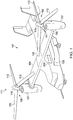
- FIG. 1 shows a schematic diagram of an example tiltrotor aircraft 101.
- Aircraft 101 includes a fuselage 103 with attached wings 105.
- Nacelles 107 are carried at the outboard ends of wings 105 and are rotatable between the helicopter-mode position shown and a forward-facing airplane-mode position (not shown).
- Nacelles 107 carry engines and transmissions 109 for powering rotor systems 111 in rotation.
- An engine may be an internal combustion engine, an electrical power source and associated motor, or any other suitable means for powering rotor system 111.
- Each rotor system 111 is illustrated as having three blades 113.
- Spinning covers 115 and nacelles 107 substantially enclose transmission 109, obscuring transmission 109 from view in figure 1 .
- the tiltrotor aircraft 101 can include a fuel storage system 300.
- the fuel storage system 300 can be located within the fuselage 103.
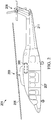
- FIG. 2 shows a schematic diagram of an example rotorcraft 201.
- Rotorcraft 201 has a rotor system 203 with multiple rotor blades 205. The pitch of each rotor blade 205 can be manipulated in order to selectively control direction, thrust, and lift of rotorcraft 201.
- Rotorcraft 201 can further include a fuselage 207, anti-torque system 209, and an empennage 211.
- the rotorcraft 201 can also include a fuel storage system 300.
- the fuel storage system 300 can be implemented in one or more fluid storage tanks, e.g., fuel cells, of the tiltrotor aircraft 101 or the rotorcraft 201 (or both), as described below.
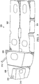
- FIG. 3 shows a schematic diagram of an example fuel storage system 300.
- the fuel storage system 300 is typical of many different fuel systems that include multiple fuel cells that are fluidly connected to each other.
- the fuel storage system 300 includes a forward port fuel cell 302, a forward starboard fuel cell 304, a center fuel cell 306, an aft fuel cell 308, and an expansion tank 310.
- the fuel storage system 300 can also include additional components, such as a fuel supply line 312 and a vent line 314.
- the fuel cells 302, 304, 306, 308, and expansion tank 310 can include fuel storage bladders formed of a strong material that is suitable for storing fuel without allowing the fuel to seep therethrough. For example, Kevlar materials are known that can be suitably used to form the walls of a fuel bladder.
- fuel cells 302, 304, 306, 308, and expansion tank 310 can lack a separate fuel storage bladder and instead be provided with a fuel resistant coating on interior surfaces thereof such that the fuel cells 302, 304, 306, 308, and expansion tank 310 can store fuel without a bladder.
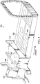
- FIG 4 shows another schematic diagram of the fuel storage system 300 shown in Figure 3 , along with portions of an airframe.
- the airframe includes several bulkheads, including bulkhead 318. Some of the bulkheads may interpose two or more fluidly-connected fuel cells. For example, bulkhead 318 interposes fuel cells 302 and 306. A hole 344 can be provided in the bulkhead 318 to serve as a passage for a fluid connection between the fuel cells 302 and 306. However, in the event of a crash or hard landing, there may be relative motion between the bulkhead 318 and the fluid connection between the fuel cells 302 and 306.
- This relative motion can cause the bulkhead 318 to puncture or sever the fluid connection between the fuel cells 302 and 306, which can result in a loss of fuel and a fire hazard. It is therefore desirable to provide a fluid connection between the various fuel cells that is resistant to damage from other parts of an aircraft, including the airframe and bulkheads, in the event of a hard landing or a crash.
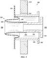
- Figure 5 shows a cross-sectional view of a first embodiment of a fluid connection system 320 according to the present disclosure.
- the fluid connection system 320 is shown connecting fuel cells 302 and 306 through bulkhead 318.
- the fluid connection system 320 includes a bellowed portion 322 that is integral to the bladder 324 of the fuel cell 306.
- the bellowed portion 322 includes at least one crest portion 326 that extends outwardly from the fuel cell 306, adjoining at least one root portion 328 that extends inwardly into the fuel cell 306, in turn adjoining a connection portion 330.
- Alternative embodiments can include additional crest portions 326 and root portions 328, alternating in series with each other.
- connection portion 330 is attached to a fitting 332 such that a fluid-tight fluid path is formed between the fuel cells 302 and 306.
- the fitting 332 includes a cylindrical portion thereof that is attached to the connection portion 330; however, in alternative embodiments, the cylindrical portion of the fitting 332 can alternatively have other non-cylindrical shapes, such as any of a variety of multi-faceted shapes that have polygonal cross-sections.
- the connection portion 330 can be connected to the fitting 332 a variety of ways, such as with the use of adhesives and/or hardware, for example a hose clamp or the like.
- the fitting 332 is connected to the bladder 334 of the fuel cell 302.
- the fitting 332 can be integral to the bladder 334 or can be attached to the bladder 334 using adhesives and/or connection hardware.
- the fuel cells 302 and 306 may be subject to forces that cause them to move relative to each other.
- the bellowed portion 322 allows for such relative motion without breaking the fluid-tight fluid connection between the two fuel cells 302 and 306.
- the bellowed portion 322 allows the fuel cells 302 and 306 to move towards and away from each other, and to move laterally (in and out of the drawing) and elevationally (up and down in the drawing) relative to each other, as well as combinations of those directions of relative movement, while still maintaining a fluid-tight fluid connection between the fuel cells 302 and 306.
- the connection system 320 further includes a guard member 340.
- the guard member 340 can be generally cylindrical in shape as shown or can have other shapes, such as any of a variety of multi-faceted shapes that have polygonal cross-sections.
- the guard member 340 can optionally include a flanged portion 342.
- the guard member 340 surrounds at least a portion of the bellowed portion 322 and at least a portion of the fitting 332. More specifically, the guard member 340 surrounds at least a portion of the crest portion 326 and connection portion 330 of the bladder 324, as well as a portion of the fitting 332.
- the guard member 340 extends through the hole 344 in the bulkhead 318, and thereby interposes the bulkhead 318 and the fluid connection between the fuel cells 302 and 306.
- the fuel cells 302 and 306 may be subject to forces that cause them to move relative to each other and relative to the bulkhead 318.
- the various components that form the fluid connection between the fuel cells 302 and 306 i.e., the bellowed portion 322 and the fitting 332
- the guard member 340 is provided in order to help prevent the bulkhead 318 from damaging the bellowed portion 322 and/or the fitting 332 in the event of a crash or hard landing.
- the guard member 340 is therefore formed of a material that is highly resistant to compressive and shearing forces, such as metal, composite, or acrylic material.
- Figure 6 shows a cross-sectional view of a second embodiment of a fluid connection system 420 according to the present disclosure.
- the second embodiment of the fluid connection system 420 is substantially the same as the first embodiment 320 shown in Figure 5 , except that the second embodiment of the fluid connection system 420 includes a guard member 440 in place of the guard member 340 shown in Figure 5 .
- the guard member 440 includes one or a pair of flange members 444 for attaching the guard member 440 to the bulkhead 318.
- the flange members 444 can be attached to the bulkhead 318 using adhesives and/or connection hardware, such as screws or nuts and bolts.
- Figure 6 shows flange members 444 on both sides of the bulkhead 318
- alternative embodiments can include a flange member 444 on only one side of the bulkhead 318.
- the guard member 440 since the guard member 440 is fixed to the bulkhead 318, the guard member 440 is more likely to stay fixed relative to the bulkhead 318 as compared to the first embodiment of the connection system 320 where the guard member 340 had more freedom to move laterally between the fuel cells 302 and 306.
- FIG 7 shows a cross-sectional view of a third embodiment of a fluid connection system 520 according to the present disclosure.
- the third embodiment of the fluid connection system 520 is substantially the same as the first embodiment 320 shown in Figure 5 , except that the third embodiment of the fluid connection system 520 includes a guard member 540 in place of the guard member 340 shown in Figure 5 .
- the guard member 540 of the third embodiment is connected to one or both of the fuel bladders 324 and 334.
- the guard member 540 is integrally formed with the fuel bladder 324.
- the guard member 540 can be attached to the fuel bladder 324, for example using adhesives, composite materials, and/or connection hardware, such as a hose clamp.
- the guard member 540 can alternatively be integral or attached to the fuel bladder 334.
- the guard member 540 since the guard member 540 is fixed relative to one or both of the fuel bladders 324 and/or 334, the guard member 540 is more likely to stay fixed between the fuel cells 302 and 306, and therefore remain fixed relative to the bellowed portion 322 and fitting 332. This helps prevent the guard member 540 from being repositioned away from the components sought to be protected from the bulkhead 318 in the event of a crash or hard landing.
Landscapes
- Engineering & Computer Science (AREA)
- Aviation & Aerospace Engineering (AREA)
- Mechanical Engineering (AREA)
- Vibration Dampers (AREA)
- Fuel-Injection Apparatus (AREA)
Abstract
Description
- This disclosure generally relates to crash-resistant fluid systems, and more specifically relates to crashworthy connection systems for fluidly-connected enclosures, including crashworthy connection systems for fluidly-connected fuel cells.
- Embodiments are illustrated by way of example in the accompanying figures, in which like reference numbers indicate similar parts, and in which:
-
Figure 1 shows a schematic diagram of an example of a tiltrotor aircraft; -
Figure 2 shows a schematic diagram of an example of a rotorcraft; -
Figure 3 shows a schematic diagram of a fuel storage system; -
Figure 4 shows the fuel storage system shown inFigure 3 with portions of an airframe; -
Figure 5 shows a cross-sectional view of a first embodiment of a fluid connection system according to the present disclosure; -
Figure 6 shows a cross-sectional view of a second embodiment of a fluid connection system according to the present disclosure; and -
Figure 7 shows a cross-sectional view of a third embodiment of a fluid connection system according to the present disclosure. - Some aircraft fluids (e.g., fuel, hydraulic fluid or other aircraft fluid) are transferred between components and systems through fluid transmission lines. In example implementations described here, the fluid transfer is through aircraft fuel transmission lines. However, in alternative embodiments, the fluid transfer can be through fluid transmission lines used to transport fuel and/or other fluids in other systems in which fluid is transported, e.g., automotive systems (e.g. automobiles, ATVs, motorcycles, etc.), fixed-wing aircraft, submersible systems, marine systems (e.g. personal watercraft, boats, etc.), agricultural systems (e.g. tractors, etc.), power equipment (e.g. generators, lawn mowers, pressure sprayers, etc.), systems that include gasoline engines, or other systems.
-
Figure 1 shows a schematic diagram of anexample tiltrotor aircraft 101.Aircraft 101 includes afuselage 103 with attachedwings 105. Nacelles 107 are carried at the outboard ends ofwings 105 and are rotatable between the helicopter-mode position shown and a forward-facing airplane-mode position (not shown). Nacelles 107 carry engines andtransmissions 109 for poweringrotor systems 111 in rotation. An engine may be an internal combustion engine, an electrical power source and associated motor, or any other suitable means for poweringrotor system 111. Eachrotor system 111 is illustrated as having threeblades 113. Spinning covers 115 andnacelles 107 substantially enclosetransmission 109, obscuringtransmission 109 from view infigure 1 . Thetiltrotor aircraft 101 can include afuel storage system 300. Thefuel storage system 300 can be located within thefuselage 103. -
Figure 2 shows a schematic diagram of anexample rotorcraft 201. Rotorcraft 201 has arotor system 203 withmultiple rotor blades 205. The pitch of eachrotor blade 205 can be manipulated in order to selectively control direction, thrust, and lift ofrotorcraft 201. Rotorcraft 201 can further include afuselage 207,anti-torque system 209, and anempennage 211. Therotorcraft 201 can also include afuel storage system 300. Thefuel storage system 300 can be implemented in one or more fluid storage tanks, e.g., fuel cells, of thetiltrotor aircraft 101 or the rotorcraft 201 (or both), as described below. -
Figure 3 shows a schematic diagram of an examplefuel storage system 300. Thefuel storage system 300 is typical of many different fuel systems that include multiple fuel cells that are fluidly connected to each other. Thefuel storage system 300 includes a forwardport fuel cell 302, a forwardstarboard fuel cell 304, acenter fuel cell 306, anaft fuel cell 308, and anexpansion tank 310. Thefuel storage system 300 can also include additional components, such as afuel supply line 312 and avent line 314. Thefuel cells expansion tank 310 can include fuel storage bladders formed of a strong material that is suitable for storing fuel without allowing the fuel to seep therethrough. For example, Kevlar materials are known that can be suitably used to form the walls of a fuel bladder. Alternatively,fuel cells expansion tank 310 can lack a separate fuel storage bladder and instead be provided with a fuel resistant coating on interior surfaces thereof such that thefuel cells expansion tank 310 can store fuel without a bladder. -
Figure 4 shows another schematic diagram of thefuel storage system 300 shown inFigure 3 , along with portions of an airframe. As shown inFigure 4 , the airframe includes several bulkheads, includingbulkhead 318. Some of the bulkheads may interpose two or more fluidly-connected fuel cells. For example,bulkhead 318 interposesfuel cells hole 344 can be provided in thebulkhead 318 to serve as a passage for a fluid connection between thefuel cells bulkhead 318 and the fluid connection between thefuel cells bulkhead 318 to puncture or sever the fluid connection between thefuel cells -
Figure 5 shows a cross-sectional view of a first embodiment of afluid connection system 320 according to the present disclosure. Thefluid connection system 320 is shown connectingfuel cells bulkhead 318. Thefluid connection system 320 includes abellowed portion 322 that is integral to thebladder 324 of thefuel cell 306. Thebellowed portion 322 includes at least onecrest portion 326 that extends outwardly from thefuel cell 306, adjoining at least oneroot portion 328 that extends inwardly into thefuel cell 306, in turn adjoining aconnection portion 330. Alternative embodiments can includeadditional crest portions 326 androot portions 328, alternating in series with each other. - The
connection portion 330 is attached to afitting 332 such that a fluid-tight fluid path is formed between thefuel cells fitting 332 includes a cylindrical portion thereof that is attached to theconnection portion 330; however, in alternative embodiments, the cylindrical portion of thefitting 332 can alternatively have other non-cylindrical shapes, such as any of a variety of multi-faceted shapes that have polygonal cross-sections. Theconnection portion 330 can be connected to the fitting 332 a variety of ways, such as with the use of adhesives and/or hardware, for example a hose clamp or the like. - The
fitting 332 is connected to thebladder 334 of thefuel cell 302. Thefitting 332 can be integral to thebladder 334 or can be attached to thebladder 334 using adhesives and/or connection hardware. - In the event of a crash or hard landing, the
fuel cells bellowed portion 322 allows for such relative motion without breaking the fluid-tight fluid connection between the twofuel cells bellowed portion 322 allows thefuel cells fuel cells - The
connection system 320 further includes aguard member 340. Theguard member 340 can be generally cylindrical in shape as shown or can have other shapes, such as any of a variety of multi-faceted shapes that have polygonal cross-sections. Theguard member 340 can optionally include a flangedportion 342. Theguard member 340 surrounds at least a portion of thebellowed portion 322 and at least a portion of thefitting 332. More specifically, theguard member 340 surrounds at least a portion of thecrest portion 326 andconnection portion 330 of thebladder 324, as well as a portion of thefitting 332. Significantly, theguard member 340 extends through thehole 344 in thebulkhead 318, and thereby interposes thebulkhead 318 and the fluid connection between thefuel cells - In the event of a crash or hard landing, the
fuel cells bulkhead 318. As a result, without theguard member 340, the various components that form the fluid connection between thefuel cells 302 and 306 (i.e., the bellowedportion 322 and the fitting 332) could be punctured, severed, or otherwise damaged by thebulkhead 318 or other debris. Therefore, theguard member 340 is provided in order to help prevent thebulkhead 318 from damaging the bellowedportion 322 and/or the fitting 332 in the event of a crash or hard landing. Preferably theguard member 340 is therefore formed of a material that is highly resistant to compressive and shearing forces, such as metal, composite, or acrylic material. -
Figure 6 shows a cross-sectional view of a second embodiment of afluid connection system 420 according to the present disclosure. The second embodiment of thefluid connection system 420 is substantially the same as thefirst embodiment 320 shown inFigure 5 , except that the second embodiment of thefluid connection system 420 includes aguard member 440 in place of theguard member 340 shown inFigure 5 . Theguard member 440 includes one or a pair offlange members 444 for attaching theguard member 440 to thebulkhead 318. Theflange members 444 can be attached to thebulkhead 318 using adhesives and/or connection hardware, such as screws or nuts and bolts. WhileFigure 6 showsflange members 444 on both sides of thebulkhead 318, alternative embodiments can include aflange member 444 on only one side of thebulkhead 318. In the second embodiment, since theguard member 440 is fixed to thebulkhead 318, theguard member 440 is more likely to stay fixed relative to thebulkhead 318 as compared to the first embodiment of theconnection system 320 where theguard member 340 had more freedom to move laterally between thefuel cells -
Figure 7 shows a cross-sectional view of a third embodiment of afluid connection system 520 according to the present disclosure. The third embodiment of thefluid connection system 520 is substantially the same as thefirst embodiment 320 shown inFigure 5 , except that the third embodiment of thefluid connection system 520 includes aguard member 540 in place of theguard member 340 shown inFigure 5 . Theguard member 540 of the third embodiment is connected to one or both of thefuel bladders guard member 540 is integrally formed with thefuel bladder 324. Alternatively, theguard member 540 can be attached to thefuel bladder 324, for example using adhesives, composite materials, and/or connection hardware, such as a hose clamp. Theguard member 540 can alternatively be integral or attached to thefuel bladder 334. In the third embodiment, since theguard member 540 is fixed relative to one or both of thefuel bladders 324 and/or 334, theguard member 540 is more likely to stay fixed between thefuel cells portion 322 andfitting 332. This helps prevent theguard member 540 from being repositioned away from the components sought to be protected from thebulkhead 318 in the event of a crash or hard landing. - While various embodiments in accordance with the principles disclosed herein have been described above, it should be understood that they have been presented by way of example only, and are not limiting. Thus, the breadth and scope of the claims should not be limited by any of the above-described exemplary embodiments, but should be defined only in accordance with the claims and their equivalents issuing from this disclosure. Furthermore, the above advantages and features are provided in described embodiments, but shall not limit the application of such issued claims to processes and structures accomplishing any or all of the above advantages.
Claims (15)
- A fluid connection system comprising:a first bladder configured to store up to a first predetermined amount of fluid, the first bladder including having a bellowed portion that surrounds a connection portion;a fitting connected to the connection portion of the first bladder, the connected fitting and connection portion being connected so as to provide a fluid-tight path through which the fluid can travel to and from the first bladder; anda guard member extending about an outer periphery of at least a portion of the bellowed portion of the first bladder and at least a portion of the fitting.
- A fluid connection system for fluidly connecting a first fuel cell on a first side of a bulkhead to a second fuel cell on a second side of the bulkhead, the system comprising:a bellowed portion of a first fuel bladder, the first fuel bladder being configured for retaining fuel within the first fuel cell, the bellowed portion including a connection portion;a fitting attached between the connection portion and a second bladder, the second bladder being configured for retaining fuel within the second fuel cell,wherein the fitting provides a fluid path between the first and second bladders; anda guard member extending about an outer periphery of at least a portion of the bellowed portion and at least a portion of the fitting.
- The system of claim 1 or claim 2, wherein the bellowed portion includes a crest portion and a root portion.
- The system of claim 3, wherein the guard member extends about the crest portion of the bellowed portion of the first bladder.
- The system of claim 3 or claim 4, wherein the crest portion surrounds the root portion, and the root portion surrounds the connection portion.
- The system of any preceding claim directly or indirectly dependent on claim 1, further comprising a second bladder, wherein the fitting is connected to the second bladder, and wherein the fluid-tight path is between the first and second bladders.
- The system of claim 6, wherein the bellowed portion is configured to allow movement of the first and second bladders relative to each other while maintain the fluid-tight path between the connection portion and the fitting.
- The system of claim 6 or claim 7, wherein the guard member includes a portion thereof that extends between the first and second bladders.
- The system of any preceding claim, wherein the guard member is attached to a bulkhead and/or wherein the guard member is attached to the first bladder.
- An aircraft comprising:an airframe having a bulkhead;first and second fuel cells on opposite sides of the bulkhead,wherein the first fuel cell includes a bellowed portion thereof, the bellowed portion of the fuel cell including a connection portion thereof;a fitting connected between the second fuel cell and the connection portion of the first fuel cell for providing a fluid connection the first and second fuel cells; anda guard member extending about an outer periphery of at least a portion of the fitting and the bellowed portion of the first fuel cell.
- The aircraft of claim 10, wherein the bellowed portion includes a crest portion and a root portion.
- The aircraft of claim 11, wherein the guard member extends about the crest portion of the bellowed portion of the first bladder.
- The aircraft of any one of claims 10 to 12, wherein the guard member is attached to the bulkhead.
- The aircraft of any one of claims 10 to 13, wherein the guard member is attached to a first bladder, the first bladder being configured for retaining fuel within the first fuel cell.
- The aircraft of any one of claims 10 to 14, wherein the guard member includes a portion thereof that extends between the first and second fuel cells.
Applications Claiming Priority (1)
| Application Number | Priority Date | Filing Date | Title |
|---|---|---|---|
| US15/267,581 US10710699B2 (en) | 2016-09-16 | 2016-09-16 | Connection apparatus for improving the crashworthiness of aircraft fluid systems |
Publications (2)
| Publication Number | Publication Date |
|---|---|
| EP3296214A1 true EP3296214A1 (en) | 2018-03-21 |
| EP3296214B1 EP3296214B1 (en) | 2018-10-24 |
Family
ID=57233308
Family Applications (1)
| Application Number | Title | Priority Date | Filing Date |
|---|---|---|---|
| EP16196094.3A Active EP3296214B1 (en) | 2016-09-16 | 2016-10-27 | Apparatus for improving the crashworthiness of aircraft fluid systems |
Country Status (2)
| Country | Link |
|---|---|
| US (1) | US10710699B2 (en) |
| EP (1) | EP3296214B1 (en) |
Cited By (2)
| Publication number | Priority date | Publication date | Assignee | Title |
|---|---|---|---|---|
| EP3628582A1 (en) * | 2018-09-27 | 2020-04-01 | Bell Helicopter Textron Inc. | System and method for enhanced fuel cell protection from adjacent damaged components |
| US20230095015A1 (en) * | 2021-09-24 | 2023-03-30 | Bell Textron Inc. | Shaped aircraft fuel cells, systems and methods for enhanced crashworthiness |
Families Citing this family (1)
| Publication number | Priority date | Publication date | Assignee | Title |
|---|---|---|---|---|
| US12525623B2 (en) | 2022-06-10 | 2026-01-13 | Response Technologies, Llc | Fuel cell and method of forming a fuel cell |
Citations (2)
| Publication number | Priority date | Publication date | Assignee | Title |
|---|---|---|---|---|
| US4335905A (en) * | 1979-05-07 | 1982-06-22 | Pneumatiques Caoutchouc Manufacture Et Plastiques Kleber-Colombes | Tanks and connecting ducts therefor |
| US20150001843A1 (en) * | 2013-06-28 | 2015-01-01 | Airbus Helicopters | Removable coupling device for coupling together two flexible pipes |
Family Cites Families (13)
| Publication number | Priority date | Publication date | Assignee | Title |
|---|---|---|---|---|
| US1015180A (en) * | 1910-01-19 | 1912-01-16 | Herman Lange | Fluid-tight expansion-joint. |
| US3035797A (en) * | 1959-01-26 | 1962-05-22 | Neuschotz Robert | Detachable connector assembly for fuel cells |
| US4307744A (en) * | 1979-12-12 | 1981-12-29 | Aeroquip Corporation | Frangible intertank valve assembly |
| US4323094A (en) * | 1980-11-14 | 1982-04-06 | United Technologies Corporation | Crashworthy aircraft fuel storage system |
| FR2643892B1 (en) * | 1989-03-03 | 1991-06-14 | Caoutchouc Manuf Plastique | SELF-SEALING CONNECTION DEVICE BETWEEN CONTAINERS |
| AT4835U1 (en) * | 2000-11-13 | 2001-12-27 | Tesma Motoren Getriebetechnik | FUEL TANK WITH A PIPE |
| DE10229803B4 (en) * | 2002-07-03 | 2006-07-27 | Eurocopter Deutschland Gmbh | Connecting arrangement for releasably connecting a first flexible tank with a second flexible tank of an aircraft |
| US7051979B2 (en) * | 2004-01-29 | 2006-05-30 | The Boeing Company | Auxiliary fuel tank systems for aircraft and methods for their manufacture and use |
| US7464966B2 (en) * | 2004-06-30 | 2008-12-16 | Tokai Rubber Industries, Inc. | Through-panel fixing device for piping member |
| FI122871B (en) * | 2010-09-10 | 2012-08-15 | Waertsilae Finland Oy | LNG containers |
| US20140050424A1 (en) * | 2012-08-16 | 2014-02-20 | Jacob N. Hilsenrath | Beverage container and an easily storable beverage dispenser |
| WO2014108884A1 (en) * | 2013-01-14 | 2014-07-17 | Aerazur S.A | Lever quick connect intercom fitting |
| WO2015089206A1 (en) * | 2013-12-10 | 2015-06-18 | Humphreys David D | Sanitary lid assembly for container and methods of producing and using same |
-
2016
- 2016-09-16 US US15/267,581 patent/US10710699B2/en active Active
- 2016-10-27 EP EP16196094.3A patent/EP3296214B1/en active Active
Patent Citations (2)
| Publication number | Priority date | Publication date | Assignee | Title |
|---|---|---|---|---|
| US4335905A (en) * | 1979-05-07 | 1982-06-22 | Pneumatiques Caoutchouc Manufacture Et Plastiques Kleber-Colombes | Tanks and connecting ducts therefor |
| US20150001843A1 (en) * | 2013-06-28 | 2015-01-01 | Airbus Helicopters | Removable coupling device for coupling together two flexible pipes |
Cited By (4)
| Publication number | Priority date | Publication date | Assignee | Title |
|---|---|---|---|---|
| EP3628582A1 (en) * | 2018-09-27 | 2020-04-01 | Bell Helicopter Textron Inc. | System and method for enhanced fuel cell protection from adjacent damaged components |
| US11332258B2 (en) | 2018-09-27 | 2022-05-17 | Textron Innovations Inc. | Method for enhanced fuel cell protection from adjacent damaged components |
| US20230095015A1 (en) * | 2021-09-24 | 2023-03-30 | Bell Textron Inc. | Shaped aircraft fuel cells, systems and methods for enhanced crashworthiness |
| US12312064B2 (en) * | 2021-09-24 | 2025-05-27 | Textron Innovations Inc. | Shaped aircraft fuel cells, systems and methods for enhanced crashworthiness |
Also Published As
| Publication number | Publication date |
|---|---|
| US10710699B2 (en) | 2020-07-14 |
| US20180079480A1 (en) | 2018-03-22 |
| EP3296214B1 (en) | 2018-10-24 |
Similar Documents
| Publication | Publication Date | Title |
|---|---|---|
| US11738874B2 (en) | Aircraft having hybrid-electric propulsion system with electric storage located in fuselage | |
| EP3524526B1 (en) | Fuselage embedded fuel tank | |
| US9481457B2 (en) | Vertical take-off and landing aircraft with variable wing geometry | |
| CN108602558B (en) | Multi-rotor aircraft | |
| US5975464A (en) | Aircraft with removable structural payload module | |
| US20210031934A1 (en) | Aircraft having hybrid-electric propulsion system with electric storage located in fuselage | |
| US10807733B2 (en) | Puncture-resistant storage systems and devices | |
| US10710699B2 (en) | Connection apparatus for improving the crashworthiness of aircraft fluid systems | |
| US9981734B2 (en) | Cross-wing driveshaft channel | |
| US20200102053A1 (en) | Watertight electric actuator for a trim tab assembly or wake gate assembly | |
| EP3048048B1 (en) | An aircraft | |
| EP3599157B1 (en) | Wing assembly with fluid pipe | |
| US9527551B2 (en) | Propulsion system for a vessel | |
| EP2671795A1 (en) | Composite material structure and aircraft wing provided therewith | |
| WO2002024529A1 (en) | Roll on - roll off, portable aerial spraying, particulate dispersal, and refueling systems apparatus | |
| US11820511B2 (en) | Unmanned aerial vehicle and associated method for reducing drag during flight of an unmanned aerial vehicle | |
| US10364039B2 (en) | Deformable clips for an aircraft fuel systems | |
| US9340279B2 (en) | Fluid transfer chamber for aircraft fluid transmission lines | |
| EP3597527A1 (en) | Pressure bulkhead and method of installation | |
| CN206171802U (en) | Unmanned helicopter of microlight -type | |
| EP3628582B1 (en) | System and method for enhanced fuel cell protection from adjacent damaged components | |
| EP4530195B1 (en) | Aircraft tank device for increasing a flight range and a wing area of an aircraft as well as aircraft | |
| US20200140107A1 (en) | Engine mounted aircraft gearbox disposed in pylon | |
| EP4574675A1 (en) | Aircraft with fuel tanks | |
| US3698659A (en) | Ferry system |
Legal Events
| Date | Code | Title | Description |
|---|---|---|---|
| PUAI | Public reference made under article 153(3) epc to a published international application that has entered the european phase |
Free format text: ORIGINAL CODE: 0009012 |
|
| 17P | Request for examination filed |
Effective date: 20161027 |
|
| AK | Designated contracting states |
Kind code of ref document: A1 Designated state(s): AL AT BE BG CH CY CZ DE DK EE ES FI FR GB GR HR HU IE IS IT LI LT LU LV MC MK MT NL NO PL PT RO RS SE SI SK SM TR |
|
| AX | Request for extension of the european patent |
Extension state: BA ME |
|
| GRAP | Despatch of communication of intention to grant a patent |
Free format text: ORIGINAL CODE: EPIDOSNIGR1 |
|
| INTG | Intention to grant announced |
Effective date: 20180420 |
|
| GRAS | Grant fee paid |
Free format text: ORIGINAL CODE: EPIDOSNIGR3 |
|
| GRAJ | Information related to disapproval of communication of intention to grant by the applicant or resumption of examination proceedings by the epo deleted |
Free format text: ORIGINAL CODE: EPIDOSDIGR1 |
|
| GRAL | Information related to payment of fee for publishing/printing deleted |
Free format text: ORIGINAL CODE: EPIDOSDIGR3 |
|
| GRAR | Information related to intention to grant a patent recorded |
Free format text: ORIGINAL CODE: EPIDOSNIGR71 |
|
| GRAA | (expected) grant |
Free format text: ORIGINAL CODE: 0009210 |
|
| INTC | Intention to grant announced (deleted) | ||
| INTG | Intention to grant announced |
Effective date: 20180905 |
|
| AK | Designated contracting states |
Kind code of ref document: B1 Designated state(s): AL AT BE BG CH CY CZ DE DK EE ES FI FR GB GR HR HU IE IS IT LI LT LU LV MC MK MT NL NO PL PT RO RS SE SI SK SM TR |
|
| REG | Reference to a national code |
Ref country code: CH Ref legal event code: EP |
|
| REG | Reference to a national code |
Ref country code: IE Ref legal event code: FG4D |
|
| REG | Reference to a national code |
Ref country code: DE Ref legal event code: R096 Ref document number: 602016006624 Country of ref document: DE Ref country code: AT Ref legal event code: REF Ref document number: 1056378 Country of ref document: AT Kind code of ref document: T Effective date: 20181115 |
|
| REG | Reference to a national code |
Ref country code: NL Ref legal event code: MP Effective date: 20181024 |
|
| REG | Reference to a national code |
Ref country code: LT Ref legal event code: MG4D |
|
| REG | Reference to a national code |
Ref country code: AT Ref legal event code: MK05 Ref document number: 1056378 Country of ref document: AT Kind code of ref document: T Effective date: 20181024 |
|
| PG25 | Lapsed in a contracting state [announced via postgrant information from national office to epo] |
Ref country code: NL Free format text: LAPSE BECAUSE OF FAILURE TO SUBMIT A TRANSLATION OF THE DESCRIPTION OR TO PAY THE FEE WITHIN THE PRESCRIBED TIME-LIMIT Effective date: 20181024 |
|
| PG25 | Lapsed in a contracting state [announced via postgrant information from national office to epo] |
Ref country code: NO Free format text: LAPSE BECAUSE OF FAILURE TO SUBMIT A TRANSLATION OF THE DESCRIPTION OR TO PAY THE FEE WITHIN THE PRESCRIBED TIME-LIMIT Effective date: 20190124 Ref country code: LT Free format text: LAPSE BECAUSE OF FAILURE TO SUBMIT A TRANSLATION OF THE DESCRIPTION OR TO PAY THE FEE WITHIN THE PRESCRIBED TIME-LIMIT Effective date: 20181024 Ref country code: HR Free format text: LAPSE BECAUSE OF FAILURE TO SUBMIT A TRANSLATION OF THE DESCRIPTION OR TO PAY THE FEE WITHIN THE PRESCRIBED TIME-LIMIT Effective date: 20181024 Ref country code: PL Free format text: LAPSE BECAUSE OF FAILURE TO SUBMIT A TRANSLATION OF THE DESCRIPTION OR TO PAY THE FEE WITHIN THE PRESCRIBED TIME-LIMIT Effective date: 20181024 Ref country code: BG Free format text: LAPSE BECAUSE OF FAILURE TO SUBMIT A TRANSLATION OF THE DESCRIPTION OR TO PAY THE FEE WITHIN THE PRESCRIBED TIME-LIMIT Effective date: 20190124 Ref country code: LV Free format text: LAPSE BECAUSE OF FAILURE TO SUBMIT A TRANSLATION OF THE DESCRIPTION OR TO PAY THE FEE WITHIN THE PRESCRIBED TIME-LIMIT Effective date: 20181024 Ref country code: FI Free format text: LAPSE BECAUSE OF FAILURE TO SUBMIT A TRANSLATION OF THE DESCRIPTION OR TO PAY THE FEE WITHIN THE PRESCRIBED TIME-LIMIT Effective date: 20181024 Ref country code: ES Free format text: LAPSE BECAUSE OF FAILURE TO SUBMIT A TRANSLATION OF THE DESCRIPTION OR TO PAY THE FEE WITHIN THE PRESCRIBED TIME-LIMIT Effective date: 20181024 Ref country code: AT Free format text: LAPSE BECAUSE OF FAILURE TO SUBMIT A TRANSLATION OF THE DESCRIPTION OR TO PAY THE FEE WITHIN THE PRESCRIBED TIME-LIMIT Effective date: 20181024 Ref country code: IS Free format text: LAPSE BECAUSE OF FAILURE TO SUBMIT A TRANSLATION OF THE DESCRIPTION OR TO PAY THE FEE WITHIN THE PRESCRIBED TIME-LIMIT Effective date: 20190224 |
|
| PG25 | Lapsed in a contracting state [announced via postgrant information from national office to epo] |
Ref country code: PT Free format text: LAPSE BECAUSE OF FAILURE TO SUBMIT A TRANSLATION OF THE DESCRIPTION OR TO PAY THE FEE WITHIN THE PRESCRIBED TIME-LIMIT Effective date: 20190224 Ref country code: GR Free format text: LAPSE BECAUSE OF FAILURE TO SUBMIT A TRANSLATION OF THE DESCRIPTION OR TO PAY THE FEE WITHIN THE PRESCRIBED TIME-LIMIT Effective date: 20190125 Ref country code: RS Free format text: LAPSE BECAUSE OF FAILURE TO SUBMIT A TRANSLATION OF THE DESCRIPTION OR TO PAY THE FEE WITHIN THE PRESCRIBED TIME-LIMIT Effective date: 20181024 Ref country code: AL Free format text: LAPSE BECAUSE OF FAILURE TO SUBMIT A TRANSLATION OF THE DESCRIPTION OR TO PAY THE FEE WITHIN THE PRESCRIBED TIME-LIMIT Effective date: 20181024 Ref country code: SE Free format text: LAPSE BECAUSE OF FAILURE TO SUBMIT A TRANSLATION OF THE DESCRIPTION OR TO PAY THE FEE WITHIN THE PRESCRIBED TIME-LIMIT Effective date: 20181024 |
|
| REG | Reference to a national code |
Ref country code: BE Ref legal event code: MM Effective date: 20181031 |
|
| PG25 | Lapsed in a contracting state [announced via postgrant information from national office to epo] |
Ref country code: LU Free format text: LAPSE BECAUSE OF NON-PAYMENT OF DUE FEES Effective date: 20181027 |
|
| REG | Reference to a national code |
Ref country code: IE Ref legal event code: MM4A |
|
| REG | Reference to a national code |
Ref country code: DE Ref legal event code: R097 Ref document number: 602016006624 Country of ref document: DE |
|
| PG25 | Lapsed in a contracting state [announced via postgrant information from national office to epo] |
Ref country code: DK Free format text: LAPSE BECAUSE OF FAILURE TO SUBMIT A TRANSLATION OF THE DESCRIPTION OR TO PAY THE FEE WITHIN THE PRESCRIBED TIME-LIMIT Effective date: 20181024 Ref country code: CZ Free format text: LAPSE BECAUSE OF FAILURE TO SUBMIT A TRANSLATION OF THE DESCRIPTION OR TO PAY THE FEE WITHIN THE PRESCRIBED TIME-LIMIT Effective date: 20181024 |
|
| PG25 | Lapsed in a contracting state [announced via postgrant information from national office to epo] |
Ref country code: MC Free format text: LAPSE BECAUSE OF FAILURE TO SUBMIT A TRANSLATION OF THE DESCRIPTION OR TO PAY THE FEE WITHIN THE PRESCRIBED TIME-LIMIT Effective date: 20181024 Ref country code: SK Free format text: LAPSE BECAUSE OF FAILURE TO SUBMIT A TRANSLATION OF THE DESCRIPTION OR TO PAY THE FEE WITHIN THE PRESCRIBED TIME-LIMIT Effective date: 20181024 Ref country code: BE Free format text: LAPSE BECAUSE OF NON-PAYMENT OF DUE FEES Effective date: 20181031 Ref country code: EE Free format text: LAPSE BECAUSE OF FAILURE TO SUBMIT A TRANSLATION OF THE DESCRIPTION OR TO PAY THE FEE WITHIN THE PRESCRIBED TIME-LIMIT Effective date: 20181024 Ref country code: SM Free format text: LAPSE BECAUSE OF FAILURE TO SUBMIT A TRANSLATION OF THE DESCRIPTION OR TO PAY THE FEE WITHIN THE PRESCRIBED TIME-LIMIT Effective date: 20181024 Ref country code: RO Free format text: LAPSE BECAUSE OF FAILURE TO SUBMIT A TRANSLATION OF THE DESCRIPTION OR TO PAY THE FEE WITHIN THE PRESCRIBED TIME-LIMIT Effective date: 20181024 |
|
| PLBE | No opposition filed within time limit |
Free format text: ORIGINAL CODE: 0009261 |
|
| STAA | Information on the status of an ep patent application or granted ep patent |
Free format text: STATUS: NO OPPOSITION FILED WITHIN TIME LIMIT |
|
| 26N | No opposition filed |
Effective date: 20190725 |
|
| PG25 | Lapsed in a contracting state [announced via postgrant information from national office to epo] |
Ref country code: IE Free format text: LAPSE BECAUSE OF NON-PAYMENT OF DUE FEES Effective date: 20181027 |
|
| PG25 | Lapsed in a contracting state [announced via postgrant information from national office to epo] |
Ref country code: MT Free format text: LAPSE BECAUSE OF NON-PAYMENT OF DUE FEES Effective date: 20181027 |
|
| PG25 | Lapsed in a contracting state [announced via postgrant information from national office to epo] |
Ref country code: TR Free format text: LAPSE BECAUSE OF FAILURE TO SUBMIT A TRANSLATION OF THE DESCRIPTION OR TO PAY THE FEE WITHIN THE PRESCRIBED TIME-LIMIT Effective date: 20181024 |
|
| REG | Reference to a national code |
Ref country code: CH Ref legal event code: PL |
|
| PG25 | Lapsed in a contracting state [announced via postgrant information from national office to epo] |
Ref country code: CY Free format text: LAPSE BECAUSE OF FAILURE TO SUBMIT A TRANSLATION OF THE DESCRIPTION OR TO PAY THE FEE WITHIN THE PRESCRIBED TIME-LIMIT Effective date: 20181024 Ref country code: MK Free format text: LAPSE BECAUSE OF NON-PAYMENT OF DUE FEES Effective date: 20181024 Ref country code: HU Free format text: LAPSE BECAUSE OF FAILURE TO SUBMIT A TRANSLATION OF THE DESCRIPTION OR TO PAY THE FEE WITHIN THE PRESCRIBED TIME-LIMIT; INVALID AB INITIO Effective date: 20161027 |
|
| PG25 | Lapsed in a contracting state [announced via postgrant information from national office to epo] |
Ref country code: LI Free format text: LAPSE BECAUSE OF NON-PAYMENT OF DUE FEES Effective date: 20191031 Ref country code: CH Free format text: LAPSE BECAUSE OF NON-PAYMENT OF DUE FEES Effective date: 20191031 |
|
| PG25 | Lapsed in a contracting state [announced via postgrant information from national office to epo] |
Ref country code: SI Free format text: LAPSE BECAUSE OF NON-PAYMENT OF DUE FEES Effective date: 20181027 |
|
| P01 | Opt-out of the competence of the unified patent court (upc) registered |
Effective date: 20230602 |
|
| PGFP | Annual fee paid to national office [announced via postgrant information from national office to epo] |
Ref country code: DE Payment date: 20251029 Year of fee payment: 10 |
|
| PGFP | Annual fee paid to national office [announced via postgrant information from national office to epo] |
Ref country code: GB Payment date: 20251027 Year of fee payment: 10 |
|
| PGFP | Annual fee paid to national office [announced via postgrant information from national office to epo] |
Ref country code: IT Payment date: 20251021 Year of fee payment: 10 |
|
| PGFP | Annual fee paid to national office [announced via postgrant information from national office to epo] |
Ref country code: FR Payment date: 20251027 Year of fee payment: 10 |