EP3296213A1 - Cross-wing driveshaft channel - Google Patents
Cross-wing driveshaft channel Download PDFInfo
- Publication number
- EP3296213A1 EP3296213A1 EP17191747.9A EP17191747A EP3296213A1 EP 3296213 A1 EP3296213 A1 EP 3296213A1 EP 17191747 A EP17191747 A EP 17191747A EP 3296213 A1 EP3296213 A1 EP 3296213A1
- Authority
- EP
- European Patent Office
- Prior art keywords
- wing
- channel
- driveshaft
- side surfaces
- aircraft
- Prior art date
- Legal status (The legal status is an assumption and is not a legal conclusion. Google has not performed a legal analysis and makes no representation as to the accuracy of the status listed.)
- Granted
Links
Images


Classifications
-
- B—PERFORMING OPERATIONS; TRANSPORTING
- B64—AIRCRAFT; AVIATION; COSMONAUTICS
- B64C—AEROPLANES; HELICOPTERS
- B64C3/00—Wings
- B64C3/34—Tanks constructed integrally with wings, e.g. for fuel or water
-
- B—PERFORMING OPERATIONS; TRANSPORTING
- B64—AIRCRAFT; AVIATION; COSMONAUTICS
- B64C—AEROPLANES; HELICOPTERS
- B64C29/00—Aircraft capable of landing or taking-off vertically, e.g. vertical take-off and landing [VTOL] aircraft
- B64C29/0008—Aircraft capable of landing or taking-off vertically, e.g. vertical take-off and landing [VTOL] aircraft having its flight directional axis horizontal when grounded
- B64C29/0016—Aircraft capable of landing or taking-off vertically, e.g. vertical take-off and landing [VTOL] aircraft having its flight directional axis horizontal when grounded the lift during taking-off being created by free or ducted propellers or by blowers
- B64C29/0033—Aircraft capable of landing or taking-off vertically, e.g. vertical take-off and landing [VTOL] aircraft having its flight directional axis horizontal when grounded the lift during taking-off being created by free or ducted propellers or by blowers the propellers being tiltable relative to the fuselage
-
- B—PERFORMING OPERATIONS; TRANSPORTING
- B64—AIRCRAFT; AVIATION; COSMONAUTICS
- B64C—AEROPLANES; HELICOPTERS
- B64C3/00—Wings
- B64C3/26—Construction, shape, or attachment of separate skins, e.g. panels
-
- B—PERFORMING OPERATIONS; TRANSPORTING
- B64—AIRCRAFT; AVIATION; COSMONAUTICS
- B64C—AEROPLANES; HELICOPTERS
- B64C3/00—Wings
- B64C3/32—Wings specially adapted for mounting power plant
-
- B—PERFORMING OPERATIONS; TRANSPORTING
- B64—AIRCRAFT; AVIATION; COSMONAUTICS
- B64D—EQUIPMENT FOR FITTING IN OR TO AIRCRAFT; FLIGHT SUITS; PARACHUTES; ARRANGEMENT OR MOUNTING OF POWER PLANTS OR PROPULSION TRANSMISSIONS IN AIRCRAFT
- B64D35/00—Transmitting power from power plants to propellers or rotors; Arrangements of transmissions
- B64D35/04—Transmitting power from power plants to propellers or rotors; Arrangements of transmissions characterised by the transmission driving a plurality of propellers or rotors
-
- B—PERFORMING OPERATIONS; TRANSPORTING
- B64—AIRCRAFT; AVIATION; COSMONAUTICS
- B64D—EQUIPMENT FOR FITTING IN OR TO AIRCRAFT; FLIGHT SUITS; PARACHUTES; ARRANGEMENT OR MOUNTING OF POWER PLANTS OR PROPULSION TRANSMISSIONS IN AIRCRAFT
- B64D35/00—Transmitting power from power plants to propellers or rotors; Arrangements of transmissions
- B64D35/04—Transmitting power from power plants to propellers or rotors; Arrangements of transmissions characterised by the transmission driving a plurality of propellers or rotors
- B64D35/06—Transmitting power from power plants to propellers or rotors; Arrangements of transmissions characterised by the transmission driving a plurality of propellers or rotors the propellers or rotors being counter-rotating
-
- B—PERFORMING OPERATIONS; TRANSPORTING
- B64—AIRCRAFT; AVIATION; COSMONAUTICS
- B64D—EQUIPMENT FOR FITTING IN OR TO AIRCRAFT; FLIGHT SUITS; PARACHUTES; ARRANGEMENT OR MOUNTING OF POWER PLANTS OR PROPULSION TRANSMISSIONS IN AIRCRAFT
- B64D37/00—Arrangements in connection with fuel supply for power plant
- B64D37/02—Tanks
- B64D37/04—Arrangement thereof in or on aircraft
-
- B—PERFORMING OPERATIONS; TRANSPORTING
- B64—AIRCRAFT; AVIATION; COSMONAUTICS
- B64D—EQUIPMENT FOR FITTING IN OR TO AIRCRAFT; FLIGHT SUITS; PARACHUTES; ARRANGEMENT OR MOUNTING OF POWER PLANTS OR PROPULSION TRANSMISSIONS IN AIRCRAFT
- B64D37/00—Arrangements in connection with fuel supply for power plant
- B64D37/02—Tanks
- B64D37/06—Constructional adaptations thereof
-
- B—PERFORMING OPERATIONS; TRANSPORTING
- B64—AIRCRAFT; AVIATION; COSMONAUTICS
- B64C—AEROPLANES; HELICOPTERS
- B64C11/00—Propellers, e.g. of ducted type; Features common to propellers and rotors for rotorcraft
- B64C11/46—Arrangements of, or constructional features peculiar to, multiple propellers
- B64C11/50—Phase synchronisation between multiple propellers
-
- B—PERFORMING OPERATIONS; TRANSPORTING
- B64—AIRCRAFT; AVIATION; COSMONAUTICS
- B64C—AEROPLANES; HELICOPTERS
- B64C27/00—Rotorcraft; Rotors peculiar thereto
- B64C27/22—Compound rotorcraft, i.e. aircraft using in flight the features of both aeroplane and rotorcraft
- B64C27/28—Compound rotorcraft, i.e. aircraft using in flight the features of both aeroplane and rotorcraft with forward-propulsion propellers pivotable to act as lifting rotors
Definitions
- the present disclosure relates to a cross-wing driveshaft channel for an aircraft wing, and more particularly, to a tiltrotor aircraft wing.
- a tiltrotor aircraft may operate in a helicopter mode by positioning the nacelles upright and in an airplane mode by positioning the nacelles forward.
- the engine driving a rotor on one side of the aircraft can be configured to drive the rotor on the other side of the aircraft by linking the propulsion system with a cross-wing driveshaft.
- the cross-wing driveshaft runs from one propulsion and gearbox system through two inboard wings and into the other rotor propulsion and gearbox system.
- the cross-wing driveshaft can be located at various locations within the inboard wing depending on the type of tiltrotor aircraft.
- the inboard wing is typically filled with fuel in fuel tanks.
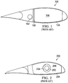
- FIG. 1 shows an exemplary prior art tiltrotor aircraft wing 100 having a driveshaft 102 located at approximately 55-60% wing chord and a fuel tank 104 with fuel 106.
- a structural intercostal 108 is provided between the driveshaft area and the fuel cell area to separate the driveshaft from the fuel 106.
- the cross-wing driveshaft is located in the aft portion of the wing and in a gap created by the structural intercostal 108. The gap created by the structural intercostal 108 limits the fuel storage capacity in the aft section of the wing.
- FIG. 2 shows a view of another exemplary prior art tiltrotor aircraft wing 200 having a driveshaft 202 located in a more forward position as compared to FIG. 1 and in the middle of the fuel tank 204.
- the driveshaft 202 runs through a tube 208 to separate the driveshaft 202 from the fuel 206.
- Access to the driveshaft 202 is very difficult and hazardous as the fuel 206 is first emptied and fuel fumes exhausted from the fuel tank 204 prior to any maintenance or inspection service.
- removing the tube 208 covering the driveshaft 202 is an additional step that is required prior to servicing the driveshaft 202.
- an aircraft wing having a wing surface including, a fuel tank located in the wing, a channel defining a cavity in the fuel tank, the channel including at least two channel ends terminating at the wing surface, a driveshaft located in the cavity; and an access panel located on the wing surface and being movable between an open position wherein access to the cavity is permitted, and a closed position wherein the cavity is at least partially covered by the access panel to inhibit access to the cavity.
- the aircraft wing is an inboard aircraft wing.
- the wing surface is an upper wing surface.
- the wing surface is a lower wing surface.
- the channel includes a first side surface and second side surfaces that extend to the channel ends.
- first and second side surfaces are substantially parallel.
- first and second side surfaces are not parallel.
- first and second side surfaces are substantially planar and at least one of the first or second side surfaces extends in a generally vertical direction.
- first and second side surfaces are substantially planar and the first and second side surfaces extend in a generally vertical direction.
- the first side surface is in contact with the second side surface.
- the channel includes a base surface in contact with the first and second side surfaces.
- the base surface is curved.
- the channel has a U-shape.
- the driveshaft is located from about 20% to about 45% of the total wing chord.
- the driveshaft is located from about 25% to about 40% of the total wing chord.
- the driveshaft is located from about 25% to about 35% of the total wing chord.
- the channel ends are adjacent to the access panel.
- the wing includes a plurality of wing supports to provide primary structural support to the wing.
- the channel spans the plurality of wing supports.
- the distal end of the channel terminates at the outermost wing support.
- Tiltrotor aircraft 300 can include a fuselage 302, a landing gear 304, a tail member 306, an inboard wing 308, an inboard wing 310, a fuel tank 312, a fuel tank 314, a cross-wing driveshaft 316, a cross-wing driveshaft 318, an outboard wing 320, an outboard wing 322, a propulsion system 324, and a propulsion system 326.
- Each propulsion system 324 and 326 includes a gearbox 333, an engine 335, and a rotatable proprotor 328 and 330, respectively.
- Each rotatable proprotor 328 and 330 has a plurality of rotor blades 332 and 334, respectively, associated therewith.
- the position of the proprotors 328 and 330 can be selectively controlled in order to selectively control direction, thrust, and lift of the tiltrotor aircraft 300.
- the cross-wing driveshafts 316 and 318 are one continuous driveshaft.
- the driveshaft 316 is separated from driveshaft 318 by a gearbox located in the fuselage 302 area.
- FIG. 3 illustrates tiltrotor aircraft 300 in helicopter mode, in which proprotors 328 and 330 are positioned substantially vertical to provide a lifting thrust.
- FIG. 4 illustrates tiltrotor aircraft 300 in an airplane mode, in which proprotors 328 and 330 are positioned substantially horizontal to provide a forward thrust in which a lifting force is supplied by inboard wings 308 and 310, respectively.
- the outboard wings 320 and 322 shown in FIGS 3 and 4 are each positioned vertically or horizontally with the proprotor 328 and 330, respectively, increase the wing span and wing aspect ratio, which thereby increases lift/draft ratio and aircraft efficiency and fuel economy as compared to a tiltrotor without outboard wings 320 and 322.
- tiltrotor aircraft can be operated such that proprotors 328 and 330 are selectively positioned between airplane mode and helicopter mode, which can be referred to as a conversion mode.
- the inboard wing 308, the outboard wing 320, and propulsion system 324 is substantially symmetric to the inboard wing 310, the outboard wing 322, and the propulsion system 326; therefore, for sake of efficiency certain features will be disclosed only with regard to the inboard wing 308, the outboard wing 322, and propulsion system 324.
- one of ordinary skill in the art would fully appreciate an understanding of the inboard wing 310, the outboard wing 322, and the propulsion system 326 based upon the disclosure herein of the inboard wing 308, the outboard wing 320, and propulsion system 324.
- the inboard wings 308 and 310, the outboard wings 320 and 322, and propulsion systems 324 and 326 are illustrated in the context of tiltrotor aircraft 300; however, the inboard wings 308 and 310, the outboard wings 320 and 322, and propulsion systems 324 and 326 can be implemented on other tiltrotor aircraft.
- an alternative embodiment may include a quad tiltrotor that has additional wing members aft of the inboard wings 308 and 310, the additional wing members can have additional outboard wings similar to the outboard wings 320 and 322, and propulsion systems similar to the propulsion systems 324 and 326.
- the stationary propulsion system is associated with the fuselage 302, where an engine located in the fuselage transfers power through a series of gears to both driveshafts 316 318 to deliver power to proprotors 328 and 330.
- Inboard wings 308 and 310 can be integrated into a variety of tiltrotor aircraft configurations with or without outboard wings 320 and 322. Further, in another embodiment, the inboard wings 308 and 310 can be used with an unmanned version of tiltrotor aircraft 300.
- the inboard wing 308 is located adjacent to, connected to, or near the fuselage 302.
- the inboard wing 308 includes an upper wing surface 340, a lower wing surface 342, aft section 344, and a forward section 346.
- the driveshaft 316 is disposed within the wing 308 and the distal end of the driveshaft 316 is in mechanical communication with a gearbox 333 and engine 335.
- the driveshaft 316 transfers power from an engine 335 in the propulsion system 324 to driveshaft 318, which transfers power to the propulsion system 326.
- Driveshafts 316 and 318 are each disposed within a channel 336 and 338, respectively.
- the driveshaft 316 is located in a forward area of the wing from about 20% to about 45% of the total wing chord. In another example, the driveshaft 316 is located from about 25% to about 40% of the total wing chord. In still another example, the driveshaft 316 is located from about 25% to about 35% of the total wing chord. In one embodiment, the driveshaft is located in the thickest portion T of the wing. In another example, the driveshaft 316 is generally located in thickest portion T of a tiltrotor aircraft wing 308 having a single engine mounted to the fuselage 302.
- Fuel tank 312 is a reservoir that stores fuel within the inboard wing 308. Fuel tank 312 may be integral with the housing of the wing 308 or separate from the wing structure 308. The fuel tank 312 is defined by an upper wall 350, a lower wall 352, and side walls 354 and 356. In one example, the fuel tank 312 is one or more fuel bags. The fuel tank 312 includes at least one port to connect with a fuel line for providing fuel to the engine 335.
- FIG. 5A shows channel 336 within the wing 308 and fuel tank 312.
- Channel 336 defines a cavity 313 within the fuel tank 312.
- the channel 336 separates the fuel in the fuel tank 312 from the driveshaft 316 by creating a physical barrier between the fuel area F and the driveshaft area D.
- the cavity 313 provides adequate space for the driveshaft 316 to operate and maximizes the amount of space available for fuel without compromising accessibility to the driveshaft 316.
- the distal end of the channel 336 terminates within the inboard wing 308 at the outboard end of the wing near the junction with propulsion system 324.
- the channel 336 and 338 can have ends terminating at the inboard end of the wing 308 just outboard of where the structural attachment of the wing 308 to the fuselage 302 occurs and where the fuel tank 312 ends.
- FIGS. 5A and 6 show channel 336 including first and second side surfaces 360 and 362 that terminate at channel ends 364 and 366, respectively, located at a wing 308 surface, which can be the upper and lower wing surfaces 340 and 342, respectively.
- the first and second side surfaces 360 and 362 extend vertically from a base 380 to the channel ends 364 and 366.
- the side surfaces 360 and 362 are substantially parallel.
- the side surfaces 360 and 362 are substantially planar and the first and second side surfaces 360 and 362 extend in a vertical direction from the base 380.
- the channel 336 is a U shaped channel.
- An exemplary embodiment provides that the side surfaces 360 and 362 with ends 364 and 366 terminating at the upper wing surface 340 are separate from the lower wing surface 342.
- the base 380 can be curved, substantially semi-circular, planar, or other suitable shape for connecting with each of the side surfaces 360 and 362.
- An exemplary embodiment provides that the base 380 does not contact a wing surface, for example, the base 380 is not connected to or is otherwise separated from the upper or lower wing surface 340 and 342, respectively.
- FIG. 6 illustrates a plurality of wing supports 370 in the fuel tank 312 to provide primary structural support for the inboard wing 308.
- the wing supports 370 can be integrally formed with the channel 336 as one piece or as several pieces that can be aligned and secured together to form the plurality of wing supports 370.
- the channel 336 is formed of a single unitary sheet and bent to form first side surface 360, base 380, and second side surface 362, and adhered, riveted, or otherwise attached in a suitable manner to the wing supports 370.
- the channel is formed of more than one sheet of suitable material to form the first side surface 360, base 380, and the second side surface 362, the sheets formed to the needed shape and adhered, riveted, or otherwise attached in a suitable manner to the wing supports 370.
- the distal end of channel 336 terminates at the most outboard or outermost wing support 370a, which is also known as the tip-rib, and extends through the wing 308 to the most inboard wing support 370b adjacent to or near the fuselage 302.
- the distal end of the channel 336 is at the end of the fuel tank 312.
- the channel 336 can terminate where the fuel tank 312 terminates.
- the channel 336 terminates at tank side walls 354 and 356.
- the channel 336 is a secondary support structure that attaches to and spans the wing supports 370.
- the wing supports 370 are wing ribs.
- the channel 336 forms the cavity 313 in the fuel tank 312 so as to permit access to the driveshaft 316 through an access panel 390 in a wing surface as shown in FIG. 7 .
- the access panel 390 is located on at least one of the upper or lower wing surface 340 and 342, respectively, as shown in FIGS. 5A and 7 .
- the access panel 390 is movable between an open position 392 that permits access to the cavity 313 and a closed position 394 so that the cavity 313 is at least partially covered by the access panel 390 to inhibit access to the cavity 313.
- the cavity 313 is covered by the access panel 390 to inhibit access the cavity 313.
- the access panel 390 can be secured to the wing surface 308 in any suitable manner, e.g., bolted, screwed, adhered, etc. In one embodiment shown in FIG. 7 , the access panel 390 is received in a recess 396 and bolted thereto so the access panel 390 is flush with the wing surface 340.
- An embodiment includes the channel ends 364 and 366 adjacent to the access panel 390. In another embodiment the channel ends 364 and 366 include a recess to receive the access panel 390.
- FIG. 5B shows an example of the channel 336 in the inboard wing 308.
- Certain components of the inboard wing 308 are as described above in connection with the inboard wing 308. Those components bear similar reference characters to the components of the inboard wing 308, but with a leading '4' rather than a leading '3'.
- the channel 436 includes the first and second side surfaces 460 and 462, respectively. As shown in FIG. 5B , the first and second side surfaces 460 and 462 are not parallel and provides a larger cavity area 413 for accessing the driveshaft 416.
- the side surfaces 460 and 462 are substantially planar and at least one of the first and second surfaces 460 and 462 extends in a generally vertical direction.
- An exemplary embodiment includes at least one of the first and second side surfaces 460 and 462 extending in an orientation transverse to the longitudinal axis of the inboard wing 408.
- FIG. 5C is another example of the channel 336 in the inboard wing 308.
- Certain components of the inboard wing 308 are as described above in connection with the inboard wing 308. Those components bear similar reference characters to the components of the inboard wing 308, but with a leading '5' rather than a leading '3'.
- the channel 536 includes the first and second side surfaces 560 and 562, respectively.
- the first and second side surfaces 560 and 562 terminate at channel ends 564 and 566, respectively, located at the lower wing surfaces 542 so that the driveshaft 516 can be accessed from the lower wing surface 542.
- Another exemplary embodiment provides that the side surfaces 560 and 562 with ends 564 and 566, respectively, terminate at the lower wing surface 542 and are separate from the upper wing surface 540.
- FIG. 5D is still another example of the channel 336 in the inboard wing 308.
- Certain components of the inboard wing 308 are as described above in connection with the inboard wing 308. Those components bear similar reference characters to the components of the inboard wing 308, but with a leading '6' rather than a leading '3'.
- the channel 636 includes the first and second side surfaces 660 and 662 and a base 680, respective.
- the base 680 is planar and is connected to the side surfaces 660 and 662 at generally about a right angle.
- FIG. 5E is one example of the channel 336 in the inboard wing 308.
- Certain components of the inboard wing 308 are as described above in connection with the inboard wing 308. Those components bear similar reference characters to the components of the inboard wing 308, but with a leading '7' rather than a leading '3'.
- the channel 736 includes the first and second side surfaces 760 and 762, respectively. In this example, the first side surface 760 directly contacts the second surface 762; a base is not required.
- cross-wing driveshaft channel described herein advantageously provide improved fuel storage capacity in the aft section of the wing while providing convenient access to the cross-wing driveshaft.
- R R l +k*(R u -R l ), wherein k is a variable ranging from 1 percent to 100 percent with a 1 percent increment, i.e., k is 1 percent, 2 percent, 3 percent, 4 percent, 5 percent, ..., 50 percent, 51 percent, 52 percent, ...., 95 percent, 96 percent, 97 percent, 98 percent, 99 percent, or 100 percent. Unless otherwise stated, the term "about” shall mean plus or minus 5 percent of the subsequent value.
- any numerical range defined by two R numbers as defined in the above is also specifically disclosed.
- Use of the term “optionally” with respect to any element of a claim means that the element is required, or alternatively, the element is not required, both alternatives being within the scope of the claim.
- Use of broader terms such as comprises, includes, and having should be understood to provide support for narrow terms such as consisting of, consisting essentially of, and comprised substantially of. Accordingly, the scope of protection is not limited by the description set out above but is defined by the claims that follow, the scope including all equivalents of the subject matter of the claims.
- Each and every claim is incorporated as further disclosure into the specification and the claims are embodiment(s) of the present invention.
Landscapes
- Engineering & Computer Science (AREA)
- Aviation & Aerospace Engineering (AREA)
- Mechanical Engineering (AREA)
- Tires In General (AREA)
Abstract
Description
- The present disclosure relates to a cross-wing driveshaft channel for an aircraft wing, and more particularly, to a tiltrotor aircraft wing.
- One example of an aircraft is a tiltrotor. A tiltrotor aircraft may operate in a helicopter mode by positioning the nacelles upright and in an airplane mode by positioning the nacelles forward. The engine driving a rotor on one side of the aircraft can be configured to drive the rotor on the other side of the aircraft by linking the propulsion system with a cross-wing driveshaft. The cross-wing driveshaft runs from one propulsion and gearbox system through two inboard wings and into the other rotor propulsion and gearbox system. The cross-wing driveshaft can be located at various locations within the inboard wing depending on the type of tiltrotor aircraft. The inboard wing is typically filled with fuel in fuel tanks.
-
FIG. 1 shows an exemplary prior arttiltrotor aircraft wing 100 having adriveshaft 102 located at approximately 55-60% wing chord and afuel tank 104 withfuel 106. Astructural intercostal 108 is provided between the driveshaft area and the fuel cell area to separate the driveshaft from thefuel 106. In this prior art example, the cross-wing driveshaft is located in the aft portion of the wing and in a gap created by thestructural intercostal 108. The gap created by thestructural intercostal 108 limits the fuel storage capacity in the aft section of the wing. -
FIG. 2 shows a view of another exemplary prior arttiltrotor aircraft wing 200 having adriveshaft 202 located in a more forward position as compared toFIG. 1 and in the middle of thefuel tank 204. Thedriveshaft 202 runs through atube 208 to separate thedriveshaft 202 from thefuel 206. Access to thedriveshaft 202 is very difficult and hazardous as thefuel 206 is first emptied and fuel fumes exhausted from thefuel tank 204 prior to any maintenance or inspection service. Moreover, removing thetube 208 covering thedriveshaft 202 is an additional step that is required prior to servicing thedriveshaft 202. - There is a need for improved access to a cross-wing driveshaft located in the forward area of a tiltrotor aircraft wing.
- In a first aspect, there is provided an aircraft wing having a wing surface including, a fuel tank located in the wing, a channel defining a cavity in the fuel tank, the channel including at least two channel ends terminating at the wing surface, a driveshaft located in the cavity; and an access panel located on the wing surface and being movable between an open position wherein access to the cavity is permitted, and a closed position wherein the cavity is at least partially covered by the access panel to inhibit access to the cavity.
- In an exemplary embodiment, the aircraft wing is an inboard aircraft wing.
- In one exemplary embodiment, the wing surface is an upper wing surface.
- In another exemplary embodiment, the wing surface is a lower wing surface.
- In yet another exemplary embodiment, the channel includes a first side surface and second side surfaces that extend to the channel ends.
- In an exemplary embodiment, the first and second side surfaces are substantially parallel.
- In still another exemplary embodiment, the first and second side surfaces are not parallel.
- In another exemplary embodiment, the first and second side surfaces are substantially planar and at least one of the first or second side surfaces extends in a generally vertical direction.
- In one exemplary embodiment, the first and second side surfaces are substantially planar and the first and second side surfaces extend in a generally vertical direction.
- In another embodiment, the first side surface is in contact with the second side surface.
- In still another embodiment, the channel includes a base surface in contact with the first and second side surfaces.
- In an exemplary embodiment, the base surface is curved.
- In one exemplary embodiment, the channel has a U-shape.
- In yet another embodiment, the driveshaft is located from about 20% to about 45% of the total wing chord.
- In an exemplary embodiment, the driveshaft is located from about 25% to about 40% of the total wing chord.
- In another exemplary embodiment, the driveshaft is located from about 25% to about 35% of the total wing chord.
- In an exemplary embodiment, the channel ends are adjacent to the access panel.
- In another exemplary embodiment, the wing includes a plurality of wing supports to provide primary structural support to the wing.
- In still another exemplary embodiment, the channel spans the plurality of wing supports.
- In one exemplary embodiment, the distal end of the channel terminates at the outermost wing support.
- Other aspects, features, and advantages will become apparent from the following detailed description when taken in conjunction with the accompanying drawings, which are a part of this disclosure and which illustrate, by way of example, principles of the inventions disclosed.
- The novel features believed characteristic of the embodiments of the present disclosure are set forth in the appended claims. However, the embodiments themselves, as well as a preferred mode of use, and further objectives and advantages thereof, will best be understood by reference to the following detailed description when read in conjunction with the accompanying drawings, wherein:
-
Figure 1 is a cross-sectional schematic view of a prior art example of an inboard wing of a tiltrotor aircraft, -
Figure 2 is a cross-sectional schematic view of a prior art example of an inboard wing of a tiltrotor aircraft, -
Figure 3 is a perspective view of a tiltrotor aircraft in helicopter mode, according to one example embodiment; -
Figure 4 is a top view of a tiltrotor aircraft in airplane mode, according to one example embodiment; -
Figure 5A is a cross-sectional schematic view of an inboard wing for a tiltrotor aircraft, according to one example embodiment; -
Figure 5B is a cross-sectional schematic view of an inboard wing for a tiltrotor aircraft, according to one example embodiment; -
Figure 5C is a cross-sectional schematic view of an inboard wing for a tiltrotor aircraft, according to one example embodiment; -
Figure 5D is a cross-sectional schematic view of an inboard wing for a tiltrotor aircraft, according to one example embodiment; -
Figure 5E is a cross-sectional schematic view of an inboard wing for a tiltrotor aircraft; -
Figure 6 is partial perspective view of an inboard wing for a tiltrotor aircraft including achannel 336 and a plurality of wing supports 370 without theupper wing surface 340 anddriveshaft 316, according to one example embodiment; and -
Figure 7 is a partial perspective view of an inboard wing for a tiltrotor aircraft, according to one example embodiment. - Illustrative embodiments of the apparatus and method are described below. In the interest of clarity, all features of an actual implementation may not be described in this specification. It will of course be appreciated that in the development of any such actual embodiment, numerous implementation-specific decisions must be made to achieve the developer's specific goals, such as compliance with system-related and business-related constraints, which will vary from one implementation to another. Moreover, it will be appreciated that such a development effort might be complex and time-consuming but would nevertheless be a routine undertaking for those of ordinary skill in the art having the benefit of this disclosure
- In the specification, reference may be made to the spatial relationships between various components and to the spatial orientation of various aspects of components as the devices are depicted in the attached drawings. However, as will be recognized by those skilled in the art after a complete reading of the present application, the devices, members, apparatuses, etc. described herein may be positioned in any desired orientation. Thus, the use of terms such as "above," "below," "upper," "lower," or other like terms to describe a spatial relationship between various components or to describe the spatial orientation of aspects of such components should be understood to describe a relative relationship between the components or a spatial orientation of aspects of such components, respectively, as the device described herein may be oriented in any desired direction.
- Referring to
FIGS. 3 and4 in the drawings, atiltrotor aircraft 300 is illustrated. Tiltrotoraircraft 300 can include afuselage 302, alanding gear 304, atail member 306, aninboard wing 308, aninboard wing 310, afuel tank 312, afuel tank 314, across-wing driveshaft 316, across-wing driveshaft 318, anoutboard wing 320, anoutboard wing 322, apropulsion system 324, and apropulsion system 326. Eachpropulsion system gearbox 333, anengine 335, and arotatable proprotor rotatable proprotor rotor blades proprotors tiltrotor aircraft 300. In one embodiment, thecross-wing driveshafts driveshaft 316 is separated fromdriveshaft 318 by a gearbox located in thefuselage 302 area. -
FIG. 3 illustratestiltrotor aircraft 300 in helicopter mode, in which proprotors 328 and 330 are positioned substantially vertical to provide a lifting thrust.FIG. 4 illustratestiltrotor aircraft 300 in an airplane mode, in which proprotors 328 and 330 are positioned substantially horizontal to provide a forward thrust in which a lifting force is supplied byinboard wings outboard wings FIGS 3 and4 are each positioned vertically or horizontally with theproprotor outboard wings proprotors - The
inboard wing 308, theoutboard wing 320, andpropulsion system 324 is substantially symmetric to theinboard wing 310, theoutboard wing 322, and thepropulsion system 326; therefore, for sake of efficiency certain features will be disclosed only with regard to theinboard wing 308, theoutboard wing 322, andpropulsion system 324. However, one of ordinary skill in the art would fully appreciate an understanding of theinboard wing 310, theoutboard wing 322, and thepropulsion system 326 based upon the disclosure herein of theinboard wing 308, theoutboard wing 320, andpropulsion system 324. - Further, the
inboard wings outboard wings propulsion systems tiltrotor aircraft 300; however, theinboard wings outboard wings propulsion systems inboard wings outboard wings propulsion systems fuselage 302, where an engine located in the fuselage transfers power through a series of gears to bothdriveshafts 316 318 to deliver power to proprotors 328 and 330. -
Inboard wings outboard wings inboard wings tiltrotor aircraft 300. - The
inboard wing 308 is located adjacent to, connected to, or near thefuselage 302. Theinboard wing 308 includes anupper wing surface 340, alower wing surface 342,aft section 344, and aforward section 346. Thedriveshaft 316 is disposed within thewing 308 and the distal end of thedriveshaft 316 is in mechanical communication with agearbox 333 andengine 335. Thedriveshaft 316 transfers power from anengine 335 in thepropulsion system 324 todriveshaft 318, which transfers power to thepropulsion system 326.Driveshafts channel - The
driveshaft 316 is located in a forward area of the wing from about 20% to about 45% of the total wing chord. In another example, thedriveshaft 316 is located from about 25% to about 40% of the total wing chord. In still another example, thedriveshaft 316 is located from about 25% to about 35% of the total wing chord. In one embodiment, the driveshaft is located in the thickest portion T of the wing. In another example, thedriveshaft 316 is generally located in thickest portion T of atiltrotor aircraft wing 308 having a single engine mounted to thefuselage 302. -
Fuel tank 312 is a reservoir that stores fuel within theinboard wing 308.Fuel tank 312 may be integral with the housing of thewing 308 or separate from thewing structure 308. Thefuel tank 312 is defined by anupper wall 350, alower wall 352, andside walls fuel tank 312 is one or more fuel bags. Thefuel tank 312 includes at least one port to connect with a fuel line for providing fuel to theengine 335. -
FIG. 5A showschannel 336 within thewing 308 andfuel tank 312.Channel 336 defines acavity 313 within thefuel tank 312. Thechannel 336 separates the fuel in thefuel tank 312 from thedriveshaft 316 by creating a physical barrier between the fuel area F and the driveshaft area D. Thecavity 313 provides adequate space for thedriveshaft 316 to operate and maximizes the amount of space available for fuel without compromising accessibility to thedriveshaft 316. - The distal end of the
channel 336 terminates within theinboard wing 308 at the outboard end of the wing near the junction withpropulsion system 324. Thechannel wing 308 just outboard of where the structural attachment of thewing 308 to thefuselage 302 occurs and where thefuel tank 312 ends. -
FIGS. 5A and6 show channel 336 including first and second side surfaces 360 and 362 that terminate at channel ends 364 and 366, respectively, located at awing 308 surface, which can be the upper and lower wing surfaces 340 and 342, respectively. The first and second side surfaces 360 and 362 extend vertically from a base 380 to the channel ends 364 and 366. In an embodiment, the side surfaces 360 and 362 are substantially parallel. In yet another embodiment, the side surfaces 360 and 362 are substantially planar and the first and second side surfaces 360 and 362 extend in a vertical direction from thebase 380. In an exemplary embodiment, thechannel 336 is a U shaped channel. An exemplary embodiment provides that the side surfaces 360 and 362 withends upper wing surface 340 are separate from thelower wing surface 342. - The base 380 can be curved, substantially semi-circular, planar, or other suitable shape for connecting with each of the side surfaces 360 and 362. An exemplary embodiment provides that the
base 380 does not contact a wing surface, for example, thebase 380 is not connected to or is otherwise separated from the upper orlower wing surface -
FIG. 6 illustrates a plurality of wing supports 370 in thefuel tank 312 to provide primary structural support for theinboard wing 308. The wing supports 370 can be integrally formed with thechannel 336 as one piece or as several pieces that can be aligned and secured together to form the plurality of wing supports 370. In another embodiment, thechannel 336 is formed of a single unitary sheet and bent to formfirst side surface 360,base 380, andsecond side surface 362, and adhered, riveted, or otherwise attached in a suitable manner to the wing supports 370. In yet another embodiment, the channel is formed of more than one sheet of suitable material to form thefirst side surface 360,base 380, and thesecond side surface 362, the sheets formed to the needed shape and adhered, riveted, or otherwise attached in a suitable manner to the wing supports 370. - In one embodiment, the distal end of
channel 336 terminates at the most outboard oroutermost wing support 370a, which is also known as the tip-rib, and extends through thewing 308 to the mostinboard wing support 370b adjacent to or near thefuselage 302. In another embodiment, the distal end of thechannel 336 is at the end of thefuel tank 312. Thechannel 336 can terminate where thefuel tank 312 terminates. In one embodiment, thechannel 336 terminates attank side walls - In another embodiment, the
channel 336 is a secondary support structure that attaches to and spans the wing supports 370. In one embodiment, the wing supports 370 are wing ribs. - The
channel 336 forms thecavity 313 in thefuel tank 312 so as to permit access to thedriveshaft 316 through anaccess panel 390 in a wing surface as shown inFIG. 7 . Theaccess panel 390 is located on at least one of the upper orlower wing surface FIGS. 5A and7 . Theaccess panel 390 is movable between anopen position 392 that permits access to thecavity 313 and aclosed position 394 so that thecavity 313 is at least partially covered by theaccess panel 390 to inhibit access to thecavity 313. In one embodiment, thecavity 313 is covered by theaccess panel 390 to inhibit access thecavity 313. Theaccess panel 390 can be secured to thewing surface 308 in any suitable manner, e.g., bolted, screwed, adhered, etc. In one embodiment shown inFIG. 7 , theaccess panel 390 is received in arecess 396 and bolted thereto so theaccess panel 390 is flush with thewing surface 340. An embodiment includes the channel ends 364 and 366 adjacent to theaccess panel 390. In another embodiment the channel ends 364 and 366 include a recess to receive theaccess panel 390. -
FIG. 5B shows an example of thechannel 336 in theinboard wing 308. Certain components of theinboard wing 308 are as described above in connection with theinboard wing 308. Those components bear similar reference characters to the components of theinboard wing 308, but with a leading '4' rather than a leading '3'. Thechannel 436 includes the first and second side surfaces 460 and 462, respectively. As shown inFIG. 5B , the first and second side surfaces 460 and 462 are not parallel and provides alarger cavity area 413 for accessing thedriveshaft 416. In an example, the side surfaces 460 and 462 are substantially planar and at least one of the first andsecond surfaces inboard wing 408. -
FIG. 5C is another example of thechannel 336 in theinboard wing 308. Certain components of theinboard wing 308 are as described above in connection with theinboard wing 308. Those components bear similar reference characters to the components of theinboard wing 308, but with a leading '5' rather than a leading '3'. Thechannel 536 includes the first and second side surfaces 560 and 562, respectively. The first and second side surfaces 560 and 562 terminate at channel ends 564 and 566, respectively, located at the lower wing surfaces 542 so that thedriveshaft 516 can be accessed from thelower wing surface 542. Another exemplary embodiment provides that the side surfaces 560 and 562 withends lower wing surface 542 and are separate from theupper wing surface 540. -
FIG. 5D is still another example of thechannel 336 in theinboard wing 308. Certain components of theinboard wing 308 are as described above in connection with theinboard wing 308. Those components bear similar reference characters to the components of theinboard wing 308, but with a leading '6' rather than a leading '3'. Thechannel 636 includes the first and second side surfaces 660 and 662 and abase 680, respective. Thebase 680 is planar and is connected to the side surfaces 660 and 662 at generally about a right angle. -
FIG. 5E is one example of thechannel 336 in theinboard wing 308. Certain components of theinboard wing 308 are as described above in connection with theinboard wing 308. Those components bear similar reference characters to the components of theinboard wing 308, but with a leading '7' rather than a leading '3'. Thechannel 736 includes the first and second side surfaces 760 and 762, respectively. In this example, thefirst side surface 760 directly contacts thesecond surface 762; a base is not required. - The illustrative embodiments of the cross-wing driveshaft channel described herein advantageously provide improved fuel storage capacity in the aft section of the wing while providing convenient access to the cross-wing driveshaft.
- At least one embodiment is disclosed and variations, combinations, and/or modifications of the embodiment(s) and/or features of the embodiment(s) made by a person having ordinary skill in the art within the scope of the disclosure. Alternative embodiments that result from combining, integrating, and/or omitting features of the embodiment(s) are also within the scope of the disclosure. Where numerical ranges or limitations are expressly stated, such express ranges or limitations should be understood to include iterative ranges or limitations of like magnitude falling within the expressly stated ranges or limitations (e.g., from about 1 to about 10 includes 2, 3, 4, etc.; greater than 0.10 includes 0.11, 0.12, 0.13, etc.). For example, whenever a numerical range with a lower limit, Rl, and an upper, Ru, is disclosed, any number falling within the range is specifically disclosed. In particular, the following numbers within the range are specifically disclosed: R=Rl+k*(Ru-Rl), wherein k is a variable ranging from 1 percent to 100 percent with a 1 percent increment, i.e., k is 1 percent, 2 percent, 3 percent, 4 percent, 5 percent, ..., 50 percent, 51 percent, 52 percent, ...., 95 percent, 96 percent, 97 percent, 98 percent, 99 percent, or 100 percent. Unless otherwise stated, the term "about" shall mean plus or minus 5 percent of the subsequent value. Moreover, any numerical range defined by two R numbers as defined in the above is also specifically disclosed. Use of the term "optionally" with respect to any element of a claim means that the element is required, or alternatively, the element is not required, both alternatives being within the scope of the claim. Use of broader terms such as comprises, includes, and having should be understood to provide support for narrow terms such as consisting of, consisting essentially of, and comprised substantially of. Accordingly, the scope of protection is not limited by the description set out above but is defined by the claims that follow, the scope including all equivalents of the subject matter of the claims. Each and every claim is incorporated as further disclosure into the specification and the claims are embodiment(s) of the present invention.
Claims (15)
- An aircraft wing having a wing surface comprising:a fuel tank located in the wing,a channel defining a cavity in the fuel tank, the channel comprising at least two channel ends terminating at the wing surface,a driveshaft located in the cavity; andan access panel located on the wing surface and being movable between an open position wherein access to the cavity is permitted, and a closed position wherein the cavity is at least partially covered by the access panel to inhibit access to the cavity.
- The aircraft wing of Claim 1, wherein the aircraft wing is an inboard aircraft wing.
- The aircraft wing of Claim 1 or of Claim 2, wherein:(i) the wing surface is an upper wing surface; or(ii) the wing surface is a lower wing surface.
- The aircraft wing of Claim 1 or of Claim 2 or of Claim 3, further comprising a first side surface and second side surface of the channel, the first and second side surfaces extending to the channel ends.
- The aircraft wing of Claim 4, wherein:(i) the first and second side surfaces are substantially parallel; or(ii) the first and second side surfaces are not parallel.
- The aircraft wing of Claim 4 or of Claim 5, wherein:(i) the first and second side surfaces are substantially planar and at least one of the first or second side surfaces extends in a generally vertical direction; or(ii) the first and second side surfaces are substantially planar and the first and second side surfaces extend in a generally vertical direction.
- The aircraft wing of claim 4 or of Claim 5 or of Claim 6, wherein the first side surface is in contact with the second side surface.
- The aircraft wing of Claim 4 or of any of Claims 5 to 7, further comprising a base surface in contact with the first and second side surfaces.
- The aircraft wing of Claim 8, wherein the base surface is curved.
- The aircraft wing of Claim 1 or of any preceding claim, wherein the channel has a U-shape.
- The aircraft wing of Claim 1 or of any preceding claim, wherein the driveshaft is located from about 20% to about 45% of the total wing chord; or
wherein the driveshaft is located from about 25% to about 40% of the total wing chord; or
wherein the driveshaft is located from about 25% to about 35% of the total wing chord. - The aircraft wing of Claim 1 or of any preceding claim, wherein the channel ends are adjacent to the access panel.
- The aircraft wing of Claim 1 or of any preceding claim, further comprising a plurality of wing supports to provide primary structural support to the wing.
- The aircraft wing of Claim 13, wherein the channel spans the plurality of wing supports.
- The aircraft wing of Claim 14, wherein the distal end of the channel terminates at the outermost wing support.
Applications Claiming Priority (1)
| Application Number | Priority Date | Filing Date | Title |
|---|---|---|---|
| US15/269,278 US9981734B2 (en) | 2016-09-19 | 2016-09-19 | Cross-wing driveshaft channel |
Publications (2)
| Publication Number | Publication Date |
|---|---|
| EP3296213A1 true EP3296213A1 (en) | 2018-03-21 |
| EP3296213B1 EP3296213B1 (en) | 2018-11-28 |
Family
ID=59914338
Family Applications (1)
| Application Number | Title | Priority Date | Filing Date |
|---|---|---|---|
| EP17191747.9A Active EP3296213B1 (en) | 2016-09-19 | 2017-09-19 | Cross-wing driveshaft channel |
Country Status (2)
| Country | Link |
|---|---|
| US (1) | US9981734B2 (en) |
| EP (1) | EP3296213B1 (en) |
Cited By (1)
| Publication number | Priority date | Publication date | Assignee | Title |
|---|---|---|---|---|
| US9981734B2 (en) | 2016-09-19 | 2018-05-29 | Bell Helicopter Textron Inc. | Cross-wing driveshaft channel |
Families Citing this family (12)
| Publication number | Priority date | Publication date | Assignee | Title |
|---|---|---|---|---|
| US10414483B2 (en) * | 2016-09-21 | 2019-09-17 | Bell Helicopter Textron, Inc. | Tiltrotor articulated wing extension |
| US11034445B2 (en) | 2017-11-27 | 2021-06-15 | Wing Aviation Llc | Wing structure and attachment to frame for unmanned aerial vehicles |
| US10723433B2 (en) * | 2017-11-27 | 2020-07-28 | Wing Aviation Llc | Assembly systems and methods for unmanned aerial vehicles |
| US11148798B2 (en) * | 2018-06-22 | 2021-10-19 | Textron Innovations Inc. | Engine and rotatable proprotor configurations for a tiltrotor aircraft |
| US20200017190A1 (en) * | 2018-07-12 | 2020-01-16 | Bell Helicopter Textron Inc. | Multi-spar wing arrangements |
| US10913542B2 (en) * | 2018-07-27 | 2021-02-09 | Textron Innovations Inc. | Conversion actuator and downstop striker fitting for a tiltrotor aircraft |
| US10994839B2 (en) | 2018-07-31 | 2021-05-04 | Textron Innovations Inc. | System and method for rotating a rotor of a tiltrotor aircraft |
| ES2775773B2 (en) * | 2019-01-25 | 2021-10-27 | Trillo Pedro Outon | VERTICAL TAKE-OFF AND LANDING AIRCRAFT WITH PIVOTING PROPELLERS |
| USD926665S1 (en) * | 2019-05-24 | 2021-08-03 | Alakai Technologies Corporation | Set of aircraft canards |
| US11718397B2 (en) * | 2021-05-19 | 2023-08-08 | Textron Innovations Inc. | Electric tiltrotor aircraft |
| US20240017847A1 (en) * | 2022-07-15 | 2024-01-18 | Pratt & Whitney Canada Corp. | Aircraft propulsion system with intermittent combustion engine(s) |
| WO2025196496A1 (en) * | 2024-03-18 | 2025-09-25 | Pavel Ruslanovich Andreev | Payload (variants) and air transport system (variants) comprising same |
Citations (4)
| Publication number | Priority date | Publication date | Assignee | Title |
|---|---|---|---|---|
| US1919682A (en) * | 1931-01-10 | 1933-07-25 | Giuseppe M Bellanca | Propelling mechanism for airplanes |
| US2806665A (en) * | 1953-05-21 | 1957-09-17 | Thomas F Gibson | Collapsible fuel tank for airplanes and the like |
| US20110177748A1 (en) * | 2010-01-21 | 2011-07-21 | Zhihong Luo | Vtol model aircraft |
| EP2778063A1 (en) * | 2013-03-12 | 2014-09-17 | Bell Helicopter Textron Inc. | Tiltrotor aircraft with inboard wing mounted fixed engine arrangement |
Family Cites Families (34)
| Publication number | Priority date | Publication date | Assignee | Title |
|---|---|---|---|---|
| US1499817A (en) * | 1920-12-09 | 1924-07-01 | Fokker Anthony Herman Gerard | Arrangement and disposition of fuel tanks in flying machines |
| US2478847A (en) * | 1944-10-06 | 1949-08-09 | Gen Motors Corp | Convertible helicopter-airplane |
| US2621001A (en) * | 1948-05-10 | 1952-12-09 | Alfred I Roman | Converti-plane |
| US2708081A (en) * | 1950-09-11 | 1955-05-10 | Black John Oliver | Convertible aircraft structure |
| US3181810A (en) * | 1961-02-27 | 1965-05-04 | Curtiss Wright Corp | Attitude control system for vtol aircraft |
| US3136499A (en) * | 1962-11-15 | 1964-06-09 | North American Aviation Inc | Aircraft power transmission system |
| US4925131A (en) * | 1966-05-18 | 1990-05-15 | Karl Eickmann | Aircraft with a plurality of propellers, a pipe structure for thereon holdable wings, for vertical take off and landing |
| US3567157A (en) * | 1966-12-30 | 1971-03-02 | Boeing Co | Aircraft propulsion mounting arrangement |
| US3884431A (en) * | 1974-01-14 | 1975-05-20 | Charles E Burrell | Convertible aircraft having oppositely rotating rotors |
| US4880071A (en) * | 1988-08-10 | 1989-11-14 | Tracy Stephen E | Toy air vehicle |
| US5863013A (en) * | 1991-11-20 | 1999-01-26 | Freewing Aerial Robotics Corporation | STOL/VTOL free wing aircraft with improved shock dampening and absorbing means |
| US5642982A (en) * | 1995-12-11 | 1997-07-01 | Sikorsky Aircraft Corporation | Retraction/extension mechanism for variable diameter rotors |
| US7607606B2 (en) * | 2002-09-11 | 2009-10-27 | Milde Jr Karl F | VTOL personal aircraft |
| US7866598B2 (en) * | 2008-03-06 | 2011-01-11 | Karem Aircraft, Inc. | Rotorcraft engine and rotor speed synchronization |
| WO2009126905A1 (en) * | 2008-04-11 | 2009-10-15 | Karem Aircraft, Inc. | Tilt actuation for a rotorcraft |
| US8083172B2 (en) * | 2008-04-25 | 2011-12-27 | Abe Karem | Combination spar and trunnion structure for a tilt rotor aircraft |
| US8844879B2 (en) | 2011-12-12 | 2014-09-30 | The Boeing Company | Wing variable camber trailing edge tip |
| GB201204941D0 (en) | 2012-03-21 | 2012-05-02 | Airbus Operations Ltd | A vent for an aircraft wing fuel tank |
| US8950698B1 (en) * | 2012-10-26 | 2015-02-10 | The Boeing Company | Convertible compounded rotorcraft |
| US9126678B2 (en) * | 2013-03-13 | 2015-09-08 | Bell Helicopter Textron Inc. | Spindle mounted tiltrotor pylon with fixed engine arrangement |
| US9663225B1 (en) * | 2013-08-14 | 2017-05-30 | Bell Helicopter Textron Inc. | Maintaining drive system alignment in tiltrotor aircraft |
| US9676488B2 (en) * | 2014-06-10 | 2017-06-13 | Sikorsky Aircraft Corporation | Dual dissimilar engines for an aircraft |
| US10647442B2 (en) * | 2015-01-16 | 2020-05-12 | Sikorsky Aircraft Corporation | Single engine, asymmetrical vertical take-off and landing (VTOL) aircraft |
| US20160304195A1 (en) * | 2015-04-16 | 2016-10-20 | Sikorsky Aircraft Corporation | Mission flexible, engine flexible, asymmetric vertical take-off and landing (vtol) aircraft |
| US20170174342A1 (en) * | 2015-06-12 | 2017-06-22 | Deng Huang | Vertical Takeoff Aircraft and Method |
| US10513332B2 (en) * | 2015-10-05 | 2019-12-24 | Sikorsky Aircraft Corporation | Tiltwing aircraft |
| US10589854B2 (en) * | 2015-10-07 | 2020-03-17 | Sikorsky Aircraft Corporation | Aircraft with overlapped rotors |
| US10183745B2 (en) * | 2015-12-07 | 2019-01-22 | Bell Helicopter Textron Inc. | Tiltrotor with inboard engines |
| US10457378B2 (en) * | 2016-02-08 | 2019-10-29 | Bell Textron Inc. | Mechanically Joining airframe members at solid insert |
| US10106253B2 (en) * | 2016-08-31 | 2018-10-23 | Bell Helicopter Textron Inc. | Tilting ducted fan aircraft generating a pitch control moment |
| US10377480B2 (en) * | 2016-08-10 | 2019-08-13 | Bell Helicopter Textron Inc. | Apparatus and method for directing thrust from tilting cross-flow fan wings on an aircraft |
| US10421541B2 (en) * | 2016-08-10 | 2019-09-24 | Bell Helicopter Textron Inc. | Aircraft with tilting cross-flow fan wings |
| US9981734B2 (en) * | 2016-09-19 | 2018-05-29 | Bell Helicopter Textron Inc. | Cross-wing driveshaft channel |
| US10279901B2 (en) * | 2016-09-21 | 2019-05-07 | Bell Helicopter Textron Inc. | Rotating proprotor arrangement for a tiltrotor aircraft |
-
2016
- 2016-09-19 US US15/269,278 patent/US9981734B2/en active Active
-
2017
- 2017-09-19 EP EP17191747.9A patent/EP3296213B1/en active Active
Patent Citations (4)
| Publication number | Priority date | Publication date | Assignee | Title |
|---|---|---|---|---|
| US1919682A (en) * | 1931-01-10 | 1933-07-25 | Giuseppe M Bellanca | Propelling mechanism for airplanes |
| US2806665A (en) * | 1953-05-21 | 1957-09-17 | Thomas F Gibson | Collapsible fuel tank for airplanes and the like |
| US20110177748A1 (en) * | 2010-01-21 | 2011-07-21 | Zhihong Luo | Vtol model aircraft |
| EP2778063A1 (en) * | 2013-03-12 | 2014-09-17 | Bell Helicopter Textron Inc. | Tiltrotor aircraft with inboard wing mounted fixed engine arrangement |
Cited By (1)
| Publication number | Priority date | Publication date | Assignee | Title |
|---|---|---|---|---|
| US9981734B2 (en) | 2016-09-19 | 2018-05-29 | Bell Helicopter Textron Inc. | Cross-wing driveshaft channel |
Also Published As
| Publication number | Publication date |
|---|---|
| US20180079483A1 (en) | 2018-03-22 |
| US9981734B2 (en) | 2018-05-29 |
| EP3296213B1 (en) | 2018-11-28 |
Similar Documents
| Publication | Publication Date | Title |
|---|---|---|
| US9981734B2 (en) | Cross-wing driveshaft channel | |
| RU2704771C2 (en) | Aircraft capable of vertical take-off | |
| US9884682B2 (en) | Aircraft configuration | |
| EP3299290B1 (en) | Rotating proprotor arrangement for a tiltrotor aircraft | |
| US20190084669A1 (en) | Tiltrotor with inboard engines | |
| EP3087003B1 (en) | An unmanned aerial vehicle | |
| US8708273B2 (en) | Three-wing, six tilt-propulsion unit, VTOL aircraft | |
| US8800912B2 (en) | Three wing, six-tilt propulsion unit, VTOL aircraft | |
| EP1999016B1 (en) | Convertible aircraft | |
| US10214277B1 (en) | System and method for improving fuel storage within a wing of an aircraft | |
| EP4023549B1 (en) | Wing design for removable battery | |
| DE102019112132B4 (en) | Aircraft | |
| US20140217229A1 (en) | Unmanned aerial vehicle | |
| CA3050051C (en) | A compound helicopter with a fixed wing arrangement | |
| EP3587258B1 (en) | Engine and rotatable proprotor configurations for a tiltrotor aircraft | |
| EP2778063A1 (en) | Tiltrotor aircraft with inboard wing mounted fixed engine arrangement | |
| EP3483059B1 (en) | Biplane tiltrotor aircraft | |
| CN101314409A (en) | Swallow type inclined rotation rotorcraft | |
| CN109398705A (en) | A kind of airfreighter | |
| US10364039B2 (en) | Deformable clips for an aircraft fuel systems | |
| JP2024509111A (en) | Aircraft wings including fuel tanks and fuel cells | |
| EP4530195B1 (en) | Aircraft tank device for increasing a flight range and a wing area of an aircraft as well as aircraft | |
| US10408327B2 (en) | Mounting arrangement for mounting a gear box of a rotorcraft to a fuselage of a rotorcraft | |
| CN113264181B (en) | Tailless composite helicopter | |
| DE202018000429U1 (en) | Vertical take-off (vertical whistle), horizontal aerodynamic flying unmanned aerial vehicle (UAV, unmanned aerial Verhicle), transport drone in special flying wing hybrid design |
Legal Events
| Date | Code | Title | Description |
|---|---|---|---|
| PUAI | Public reference made under article 153(3) epc to a published international application that has entered the european phase |
Free format text: ORIGINAL CODE: 0009012 |
|
| STAA | Information on the status of an ep patent application or granted ep patent |
Free format text: STATUS: REQUEST FOR EXAMINATION WAS MADE |
|
| 17P | Request for examination filed |
Effective date: 20170919 |
|
| AK | Designated contracting states |
Kind code of ref document: A1 Designated state(s): AL AT BE BG CH CY CZ DE DK EE ES FI FR GB GR HR HU IE IS IT LI LT LU LV MC MK MT NL NO PL PT RO RS SE SI SK SM TR |
|
| AX | Request for extension of the european patent |
Extension state: BA ME |
|
| STAA | Information on the status of an ep patent application or granted ep patent |
Free format text: STATUS: EXAMINATION IS IN PROGRESS |
|
| 17Q | First examination report despatched |
Effective date: 20180316 |
|
| GRAP | Despatch of communication of intention to grant a patent |
Free format text: ORIGINAL CODE: EPIDOSNIGR1 |
|
| STAA | Information on the status of an ep patent application or granted ep patent |
Free format text: STATUS: GRANT OF PATENT IS INTENDED |
|
| INTG | Intention to grant announced |
Effective date: 20180903 |
|
| GRAS | Grant fee paid |
Free format text: ORIGINAL CODE: EPIDOSNIGR3 |
|
| GRAA | (expected) grant |
Free format text: ORIGINAL CODE: 0009210 |
|
| STAA | Information on the status of an ep patent application or granted ep patent |
Free format text: STATUS: THE PATENT HAS BEEN GRANTED |
|
| AK | Designated contracting states |
Kind code of ref document: B1 Designated state(s): AL AT BE BG CH CY CZ DE DK EE ES FI FR GB GR HR HU IE IS IT LI LT LU LV MC MK MT NL NO PL PT RO RS SE SI SK SM TR |
|
| REG | Reference to a national code |
Ref country code: CH Ref legal event code: EP |
|
| REG | Reference to a national code |
Ref country code: AT Ref legal event code: REF Ref document number: 1069943 Country of ref document: AT Kind code of ref document: T Effective date: 20181215 |
|
| REG | Reference to a national code |
Ref country code: DE Ref legal event code: R096 Ref document number: 602017001087 Country of ref document: DE |
|
| REG | Reference to a national code |
Ref country code: IE Ref legal event code: FG4D |
|
| REG | Reference to a national code |
Ref country code: NL Ref legal event code: MP Effective date: 20181128 |
|
| REG | Reference to a national code |
Ref country code: LT Ref legal event code: MG4D |
|
| REG | Reference to a national code |
Ref country code: AT Ref legal event code: MK05 Ref document number: 1069943 Country of ref document: AT Kind code of ref document: T Effective date: 20181128 |
|
| PG25 | Lapsed in a contracting state [announced via postgrant information from national office to epo] |
Ref country code: LV Free format text: LAPSE BECAUSE OF FAILURE TO SUBMIT A TRANSLATION OF THE DESCRIPTION OR TO PAY THE FEE WITHIN THE PRESCRIBED TIME-LIMIT Effective date: 20181128 Ref country code: ES Free format text: LAPSE BECAUSE OF FAILURE TO SUBMIT A TRANSLATION OF THE DESCRIPTION OR TO PAY THE FEE WITHIN THE PRESCRIBED TIME-LIMIT Effective date: 20181128 Ref country code: AT Free format text: LAPSE BECAUSE OF FAILURE TO SUBMIT A TRANSLATION OF THE DESCRIPTION OR TO PAY THE FEE WITHIN THE PRESCRIBED TIME-LIMIT Effective date: 20181128 Ref country code: HR Free format text: LAPSE BECAUSE OF FAILURE TO SUBMIT A TRANSLATION OF THE DESCRIPTION OR TO PAY THE FEE WITHIN THE PRESCRIBED TIME-LIMIT Effective date: 20181128 Ref country code: IS Free format text: LAPSE BECAUSE OF FAILURE TO SUBMIT A TRANSLATION OF THE DESCRIPTION OR TO PAY THE FEE WITHIN THE PRESCRIBED TIME-LIMIT Effective date: 20190328 Ref country code: FI Free format text: LAPSE BECAUSE OF FAILURE TO SUBMIT A TRANSLATION OF THE DESCRIPTION OR TO PAY THE FEE WITHIN THE PRESCRIBED TIME-LIMIT Effective date: 20181128 Ref country code: BG Free format text: LAPSE BECAUSE OF FAILURE TO SUBMIT A TRANSLATION OF THE DESCRIPTION OR TO PAY THE FEE WITHIN THE PRESCRIBED TIME-LIMIT Effective date: 20190228 Ref country code: LT Free format text: LAPSE BECAUSE OF FAILURE TO SUBMIT A TRANSLATION OF THE DESCRIPTION OR TO PAY THE FEE WITHIN THE PRESCRIBED TIME-LIMIT Effective date: 20181128 Ref country code: NO Free format text: LAPSE BECAUSE OF FAILURE TO SUBMIT A TRANSLATION OF THE DESCRIPTION OR TO PAY THE FEE WITHIN THE PRESCRIBED TIME-LIMIT Effective date: 20190228 |
|
| PG25 | Lapsed in a contracting state [announced via postgrant information from national office to epo] |
Ref country code: RS Free format text: LAPSE BECAUSE OF FAILURE TO SUBMIT A TRANSLATION OF THE DESCRIPTION OR TO PAY THE FEE WITHIN THE PRESCRIBED TIME-LIMIT Effective date: 20181128 Ref country code: PT Free format text: LAPSE BECAUSE OF FAILURE TO SUBMIT A TRANSLATION OF THE DESCRIPTION OR TO PAY THE FEE WITHIN THE PRESCRIBED TIME-LIMIT Effective date: 20190328 Ref country code: GR Free format text: LAPSE BECAUSE OF FAILURE TO SUBMIT A TRANSLATION OF THE DESCRIPTION OR TO PAY THE FEE WITHIN THE PRESCRIBED TIME-LIMIT Effective date: 20190301 Ref country code: SE Free format text: LAPSE BECAUSE OF FAILURE TO SUBMIT A TRANSLATION OF THE DESCRIPTION OR TO PAY THE FEE WITHIN THE PRESCRIBED TIME-LIMIT Effective date: 20181128 Ref country code: AL Free format text: LAPSE BECAUSE OF FAILURE TO SUBMIT A TRANSLATION OF THE DESCRIPTION OR TO PAY THE FEE WITHIN THE PRESCRIBED TIME-LIMIT Effective date: 20181128 |
|
| PG25 | Lapsed in a contracting state [announced via postgrant information from national office to epo] |
Ref country code: NL Free format text: LAPSE BECAUSE OF FAILURE TO SUBMIT A TRANSLATION OF THE DESCRIPTION OR TO PAY THE FEE WITHIN THE PRESCRIBED TIME-LIMIT Effective date: 20181128 |
|
| PG25 | Lapsed in a contracting state [announced via postgrant information from national office to epo] |
Ref country code: DK Free format text: LAPSE BECAUSE OF FAILURE TO SUBMIT A TRANSLATION OF THE DESCRIPTION OR TO PAY THE FEE WITHIN THE PRESCRIBED TIME-LIMIT Effective date: 20181128 Ref country code: PL Free format text: LAPSE BECAUSE OF FAILURE TO SUBMIT A TRANSLATION OF THE DESCRIPTION OR TO PAY THE FEE WITHIN THE PRESCRIBED TIME-LIMIT Effective date: 20181128 Ref country code: CZ Free format text: LAPSE BECAUSE OF FAILURE TO SUBMIT A TRANSLATION OF THE DESCRIPTION OR TO PAY THE FEE WITHIN THE PRESCRIBED TIME-LIMIT Effective date: 20181128 |
|
| REG | Reference to a national code |
Ref country code: DE Ref legal event code: R097 Ref document number: 602017001087 Country of ref document: DE |
|
| PG25 | Lapsed in a contracting state [announced via postgrant information from national office to epo] |
Ref country code: RO Free format text: LAPSE BECAUSE OF FAILURE TO SUBMIT A TRANSLATION OF THE DESCRIPTION OR TO PAY THE FEE WITHIN THE PRESCRIBED TIME-LIMIT Effective date: 20181128 Ref country code: SK Free format text: LAPSE BECAUSE OF FAILURE TO SUBMIT A TRANSLATION OF THE DESCRIPTION OR TO PAY THE FEE WITHIN THE PRESCRIBED TIME-LIMIT Effective date: 20181128 Ref country code: SM Free format text: LAPSE BECAUSE OF FAILURE TO SUBMIT A TRANSLATION OF THE DESCRIPTION OR TO PAY THE FEE WITHIN THE PRESCRIBED TIME-LIMIT Effective date: 20181128 Ref country code: EE Free format text: LAPSE BECAUSE OF FAILURE TO SUBMIT A TRANSLATION OF THE DESCRIPTION OR TO PAY THE FEE WITHIN THE PRESCRIBED TIME-LIMIT Effective date: 20181128 |
|
| PLBE | No opposition filed within time limit |
Free format text: ORIGINAL CODE: 0009261 |
|
| STAA | Information on the status of an ep patent application or granted ep patent |
Free format text: STATUS: NO OPPOSITION FILED WITHIN TIME LIMIT |
|
| 26N | No opposition filed |
Effective date: 20190829 |
|
| PG25 | Lapsed in a contracting state [announced via postgrant information from national office to epo] |
Ref country code: TR Free format text: LAPSE BECAUSE OF FAILURE TO SUBMIT A TRANSLATION OF THE DESCRIPTION OR TO PAY THE FEE WITHIN THE PRESCRIBED TIME-LIMIT Effective date: 20181128 |
|
| PG25 | Lapsed in a contracting state [announced via postgrant information from national office to epo] |
Ref country code: MC Free format text: LAPSE BECAUSE OF FAILURE TO SUBMIT A TRANSLATION OF THE DESCRIPTION OR TO PAY THE FEE WITHIN THE PRESCRIBED TIME-LIMIT Effective date: 20181128 |
|
| PG25 | Lapsed in a contracting state [announced via postgrant information from national office to epo] |
Ref country code: LU Free format text: LAPSE BECAUSE OF NON-PAYMENT OF DUE FEES Effective date: 20190919 Ref country code: IE Free format text: LAPSE BECAUSE OF NON-PAYMENT OF DUE FEES Effective date: 20190919 |
|
| REG | Reference to a national code |
Ref country code: BE Ref legal event code: MM Effective date: 20190930 |
|
| PG25 | Lapsed in a contracting state [announced via postgrant information from national office to epo] |
Ref country code: BE Free format text: LAPSE BECAUSE OF NON-PAYMENT OF DUE FEES Effective date: 20190930 |
|
| REG | Reference to a national code |
Ref country code: CH Ref legal event code: PL |
|
| PG25 | Lapsed in a contracting state [announced via postgrant information from national office to epo] |
Ref country code: CY Free format text: LAPSE BECAUSE OF FAILURE TO SUBMIT A TRANSLATION OF THE DESCRIPTION OR TO PAY THE FEE WITHIN THE PRESCRIBED TIME-LIMIT Effective date: 20181128 |
|
| PG25 | Lapsed in a contracting state [announced via postgrant information from national office to epo] |
Ref country code: HU Free format text: LAPSE BECAUSE OF FAILURE TO SUBMIT A TRANSLATION OF THE DESCRIPTION OR TO PAY THE FEE WITHIN THE PRESCRIBED TIME-LIMIT; INVALID AB INITIO Effective date: 20170919 Ref country code: MT Free format text: LAPSE BECAUSE OF FAILURE TO SUBMIT A TRANSLATION OF THE DESCRIPTION OR TO PAY THE FEE WITHIN THE PRESCRIBED TIME-LIMIT Effective date: 20181128 |
|
| PG25 | Lapsed in a contracting state [announced via postgrant information from national office to epo] |
Ref country code: LI Free format text: LAPSE BECAUSE OF NON-PAYMENT OF DUE FEES Effective date: 20200930 Ref country code: CH Free format text: LAPSE BECAUSE OF NON-PAYMENT OF DUE FEES Effective date: 20200930 |
|
| PG25 | Lapsed in a contracting state [announced via postgrant information from national office to epo] |
Ref country code: SI Free format text: LAPSE BECAUSE OF FAILURE TO SUBMIT A TRANSLATION OF THE DESCRIPTION OR TO PAY THE FEE WITHIN THE PRESCRIBED TIME-LIMIT Effective date: 20181128 |
|
| PG25 | Lapsed in a contracting state [announced via postgrant information from national office to epo] |
Ref country code: MK Free format text: LAPSE BECAUSE OF FAILURE TO SUBMIT A TRANSLATION OF THE DESCRIPTION OR TO PAY THE FEE WITHIN THE PRESCRIBED TIME-LIMIT Effective date: 20181128 |
|
| P01 | Opt-out of the competence of the unified patent court (upc) registered |
Effective date: 20230602 |
|
| PGFP | Annual fee paid to national office [announced via postgrant information from national office to epo] |
Ref country code: DE Payment date: 20250929 Year of fee payment: 9 |
|
| PGFP | Annual fee paid to national office [announced via postgrant information from national office to epo] |
Ref country code: IT Payment date: 20250919 Year of fee payment: 9 |
|
| PGFP | Annual fee paid to national office [announced via postgrant information from national office to epo] |
Ref country code: GB Payment date: 20250929 Year of fee payment: 9 |
|
| PGFP | Annual fee paid to national office [announced via postgrant information from national office to epo] |
Ref country code: FR Payment date: 20250925 Year of fee payment: 9 |