EP3296212A1 - Aircraft propulsion system - Google Patents
Aircraft propulsion system Download PDFInfo
- Publication number
- EP3296212A1 EP3296212A1 EP17187444.9A EP17187444A EP3296212A1 EP 3296212 A1 EP3296212 A1 EP 3296212A1 EP 17187444 A EP17187444 A EP 17187444A EP 3296212 A1 EP3296212 A1 EP 3296212A1
- Authority
- EP
- European Patent Office
- Prior art keywords
- electrical
- network
- power
- motor
- coupled
- Prior art date
- Legal status (The legal status is an assumption and is not a legal conclusion. Google has not performed a legal analysis and makes no representation as to the accuracy of the status listed.)
- Granted
Links
- 230000001360 synchronised effect Effects 0.000 claims description 25
- 239000007789 gas Substances 0.000 claims description 23
- 238000004146 energy storage Methods 0.000 claims description 10
- 238000002485 combustion reaction Methods 0.000 claims description 6
- 238000007599 discharging Methods 0.000 claims description 6
- 239000000446 fuel Substances 0.000 claims description 6
- 230000001419 dependent effect Effects 0.000 claims description 4
- 230000006698 induction Effects 0.000 claims description 4
- UFHFLCQGNIYNRP-UHFFFAOYSA-N Hydrogen Chemical compound [H][H] UFHFLCQGNIYNRP-UHFFFAOYSA-N 0.000 claims description 2
- 239000003990 capacitor Substances 0.000 claims description 2
- 239000001257 hydrogen Substances 0.000 claims description 2
- 229910052739 hydrogen Inorganic materials 0.000 claims description 2
- 238000006243 chemical reaction Methods 0.000 description 7
- 230000001141 propulsive effect Effects 0.000 description 3
- 238000000034 method Methods 0.000 description 2
- 241000555745 Sciuridae Species 0.000 description 1
- 230000005540 biological transmission Effects 0.000 description 1
- 238000012986 modification Methods 0.000 description 1
- 230000004048 modification Effects 0.000 description 1
- 230000001052 transient effect Effects 0.000 description 1
Images


Classifications
-
- B—PERFORMING OPERATIONS; TRANSPORTING
- B64—AIRCRAFT; AVIATION; COSMONAUTICS
- B64D—EQUIPMENT FOR FITTING IN OR TO AIRCRAFT; FLIGHT SUITS; PARACHUTES; ARRANGEMENTS OR MOUNTING OF POWER PLANTS OR PROPULSION TRANSMISSIONS IN AIRCRAFT
- B64D27/00—Arrangement or mounting of power plant in aircraft; Aircraft characterised thereby
- B64D27/02—Aircraft characterised by the type or position of power plant
- B64D27/24—Aircraft characterised by the type or position of power plant using steam, electricity, or spring force
-
- B—PERFORMING OPERATIONS; TRANSPORTING
- B61—RAILWAYS
- B61C—LOCOMOTIVES; MOTOR RAILCARS
- B61C5/00—Locomotives or motor railcars with IC engines or gas turbines
-
- B—PERFORMING OPERATIONS; TRANSPORTING
- B63—SHIPS OR OTHER WATERBORNE VESSELS; RELATED EQUIPMENT
- B63H—MARINE PROPULSION OR STEERING
- B63H21/00—Use of propulsion power plant or units on vessels
- B63H21/12—Use of propulsion power plant or units on vessels the vessels being motor-driven
- B63H21/17—Use of propulsion power plant or units on vessels the vessels being motor-driven by electric motor
-
- B—PERFORMING OPERATIONS; TRANSPORTING
- B63—SHIPS OR OTHER WATERBORNE VESSELS; RELATED EQUIPMENT
- B63H—MARINE PROPULSION OR STEERING
- B63H21/00—Use of propulsion power plant or units on vessels
- B63H21/20—Use of propulsion power plant or units on vessels the vessels being powered by combinations of different types of propulsion units
-
- B—PERFORMING OPERATIONS; TRANSPORTING
- B64—AIRCRAFT; AVIATION; COSMONAUTICS
- B64D—EQUIPMENT FOR FITTING IN OR TO AIRCRAFT; FLIGHT SUITS; PARACHUTES; ARRANGEMENTS OR MOUNTING OF POWER PLANTS OR PROPULSION TRANSMISSIONS IN AIRCRAFT
- B64D27/00—Arrangement or mounting of power plant in aircraft; Aircraft characterised thereby
- B64D27/02—Aircraft characterised by the type or position of power plant
-
- B64D27/026—
-
- H—ELECTRICITY
- H02—GENERATION; CONVERSION OR DISTRIBUTION OF ELECTRIC POWER
- H02J—CIRCUIT ARRANGEMENTS OR SYSTEMS FOR SUPPLYING OR DISTRIBUTING ELECTRIC POWER; SYSTEMS FOR STORING ELECTRIC ENERGY
- H02J3/00—Circuit arrangements for ac mains or ac distribution networks
- H02J3/007—Arrangements for selectively connecting the load or loads to one or several among a plurality of power lines or power sources
-
- H—ELECTRICITY
- H02—GENERATION; CONVERSION OR DISTRIBUTION OF ELECTRIC POWER
- H02J—CIRCUIT ARRANGEMENTS OR SYSTEMS FOR SUPPLYING OR DISTRIBUTING ELECTRIC POWER; SYSTEMS FOR STORING ELECTRIC ENERGY
- H02J3/00—Circuit arrangements for ac mains or ac distribution networks
- H02J3/02—Circuit arrangements for ac mains or ac distribution networks using a single network for simultaneous distribution of power at different frequencies; using a single network for simultaneous distribution of ac power and of dc power
-
- H—ELECTRICITY
- H02—GENERATION; CONVERSION OR DISTRIBUTION OF ELECTRIC POWER
- H02J—CIRCUIT ARRANGEMENTS OR SYSTEMS FOR SUPPLYING OR DISTRIBUTING ELECTRIC POWER; SYSTEMS FOR STORING ELECTRIC ENERGY
- H02J3/00—Circuit arrangements for ac mains or ac distribution networks
- H02J3/38—Arrangements for parallely feeding a single network by two or more generators, converters or transformers
- H02J3/46—Controlling of the sharing of output between the generators, converters, or transformers
- H02J3/466—Scheduling the operation of the generators, e.g. connecting or disconnecting generators to meet a given demand
- H02J3/472—For selectively connecting the AC sources in a particular order, e.g. sequential, alternating or subsets of sources
-
- H—ELECTRICITY
- H02—GENERATION; CONVERSION OR DISTRIBUTION OF ELECTRIC POWER
- H02J—CIRCUIT ARRANGEMENTS OR SYSTEMS FOR SUPPLYING OR DISTRIBUTING ELECTRIC POWER; SYSTEMS FOR STORING ELECTRIC ENERGY
- H02J50/00—Circuit arrangements or systems for wireless supply or distribution of electric power
- H02J50/10—Circuit arrangements or systems for wireless supply or distribution of electric power using inductive coupling
-
- H—ELECTRICITY
- H02—GENERATION; CONVERSION OR DISTRIBUTION OF ELECTRIC POWER
- H02J—CIRCUIT ARRANGEMENTS OR SYSTEMS FOR SUPPLYING OR DISTRIBUTING ELECTRIC POWER; SYSTEMS FOR STORING ELECTRIC ENERGY
- H02J7/00—Circuit arrangements for charging or depolarising batteries or for supplying loads from batteries
- H02J7/34—Parallel operation in networks using both storage and other dc sources, e.g. providing buffering
-
- H—ELECTRICITY
- H02—GENERATION; CONVERSION OR DISTRIBUTION OF ELECTRIC POWER
- H02P—CONTROL OR REGULATION OF ELECTRIC MOTORS, ELECTRIC GENERATORS OR DYNAMO-ELECTRIC CONVERTERS; CONTROLLING TRANSFORMERS, REACTORS OR CHOKE COILS
- H02P5/00—Arrangements specially adapted for regulating or controlling the speed or torque of two or more electric motors
- H02P5/74—Arrangements specially adapted for regulating or controlling the speed or torque of two or more electric motors controlling two or more ac dynamo-electric motors
-
- B—PERFORMING OPERATIONS; TRANSPORTING
- B64—AIRCRAFT; AVIATION; COSMONAUTICS
- B64D—EQUIPMENT FOR FITTING IN OR TO AIRCRAFT; FLIGHT SUITS; PARACHUTES; ARRANGEMENTS OR MOUNTING OF POWER PLANTS OR PROPULSION TRANSMISSIONS IN AIRCRAFT
- B64D27/00—Arrangement or mounting of power plant in aircraft; Aircraft characterised thereby
- B64D27/02—Aircraft characterised by the type or position of power plant
- B64D27/10—Aircraft characterised by the type or position of power plant of gas-turbine type
-
- H—ELECTRICITY
- H02—GENERATION; CONVERSION OR DISTRIBUTION OF ELECTRIC POWER
- H02J—CIRCUIT ARRANGEMENTS OR SYSTEMS FOR SUPPLYING OR DISTRIBUTING ELECTRIC POWER; SYSTEMS FOR STORING ELECTRIC ENERGY
- H02J2310/00—The network for supplying or distributing electric power characterised by its spatial reach or by the load
- H02J2310/40—The network being an on-board power network, i.e. within a vehicle
- H02J2310/42—The network being an on-board power network, i.e. within a vehicle for ships or vessels
-
- H—ELECTRICITY
- H02—GENERATION; CONVERSION OR DISTRIBUTION OF ELECTRIC POWER
- H02J—CIRCUIT ARRANGEMENTS OR SYSTEMS FOR SUPPLYING OR DISTRIBUTING ELECTRIC POWER; SYSTEMS FOR STORING ELECTRIC ENERGY
- H02J2310/00—The network for supplying or distributing electric power characterised by its spatial reach or by the load
- H02J2310/40—The network being an on-board power network, i.e. within a vehicle
- H02J2310/44—The network being an on-board power network, i.e. within a vehicle for aircrafts
-
- Y—GENERAL TAGGING OF NEW TECHNOLOGICAL DEVELOPMENTS; GENERAL TAGGING OF CROSS-SECTIONAL TECHNOLOGIES SPANNING OVER SEVERAL SECTIONS OF THE IPC; TECHNICAL SUBJECTS COVERED BY FORMER USPC CROSS-REFERENCE ART COLLECTIONS [XRACs] AND DIGESTS
- Y02—TECHNOLOGIES OR APPLICATIONS FOR MITIGATION OR ADAPTATION AGAINST CLIMATE CHANGE
- Y02T—CLIMATE CHANGE MITIGATION TECHNOLOGIES RELATED TO TRANSPORTATION
- Y02T30/00—Transportation of goods or passengers via railways, e.g. energy recovery or reducing air resistance
-
- Y—GENERAL TAGGING OF NEW TECHNOLOGICAL DEVELOPMENTS; GENERAL TAGGING OF CROSS-SECTIONAL TECHNOLOGIES SPANNING OVER SEVERAL SECTIONS OF THE IPC; TECHNICAL SUBJECTS COVERED BY FORMER USPC CROSS-REFERENCE ART COLLECTIONS [XRACs] AND DIGESTS
- Y02—TECHNOLOGIES OR APPLICATIONS FOR MITIGATION OR ADAPTATION AGAINST CLIMATE CHANGE
- Y02T—CLIMATE CHANGE MITIGATION TECHNOLOGIES RELATED TO TRANSPORTATION
- Y02T50/00—Aeronautics or air transport
- Y02T50/40—Weight reduction
-
- Y—GENERAL TAGGING OF NEW TECHNOLOGICAL DEVELOPMENTS; GENERAL TAGGING OF CROSS-SECTIONAL TECHNOLOGIES SPANNING OVER SEVERAL SECTIONS OF THE IPC; TECHNICAL SUBJECTS COVERED BY FORMER USPC CROSS-REFERENCE ART COLLECTIONS [XRACs] AND DIGESTS
- Y02—TECHNOLOGIES OR APPLICATIONS FOR MITIGATION OR ADAPTATION AGAINST CLIMATE CHANGE
- Y02T—CLIMATE CHANGE MITIGATION TECHNOLOGIES RELATED TO TRANSPORTATION
- Y02T50/00—Aeronautics or air transport
- Y02T50/60—Efficient propulsion technologies, e.g. for aircraft
-
- Y—GENERAL TAGGING OF NEW TECHNOLOGICAL DEVELOPMENTS; GENERAL TAGGING OF CROSS-SECTIONAL TECHNOLOGIES SPANNING OVER SEVERAL SECTIONS OF THE IPC; TECHNICAL SUBJECTS COVERED BY FORMER USPC CROSS-REFERENCE ART COLLECTIONS [XRACs] AND DIGESTS
- Y02—TECHNOLOGIES OR APPLICATIONS FOR MITIGATION OR ADAPTATION AGAINST CLIMATE CHANGE
- Y02T—CLIMATE CHANGE MITIGATION TECHNOLOGIES RELATED TO TRANSPORTATION
- Y02T70/00—Maritime or waterways transport
- Y02T70/50—Measures to reduce greenhouse gas emissions related to the propulsion system
- Y02T70/5218—Less carbon-intensive fuels, e.g. natural gas, biofuels
- Y02T70/5236—Renewable or hybrid-electric solutions
-
- Y—GENERAL TAGGING OF NEW TECHNOLOGICAL DEVELOPMENTS; GENERAL TAGGING OF CROSS-SECTIONAL TECHNOLOGIES SPANNING OVER SEVERAL SECTIONS OF THE IPC; TECHNICAL SUBJECTS COVERED BY FORMER USPC CROSS-REFERENCE ART COLLECTIONS [XRACs] AND DIGESTS
- Y02—TECHNOLOGIES OR APPLICATIONS FOR MITIGATION OR ADAPTATION AGAINST CLIMATE CHANGE
- Y02T—CLIMATE CHANGE MITIGATION TECHNOLOGIES RELATED TO TRANSPORTATION
- Y02T90/00—Enabling technologies or technologies with a potential or indirect contribution to GHG emissions mitigation
- Y02T90/40—Application of hydrogen technology to transportation, e.g. using fuel cells
Definitions
- the present disclosure concerns an aircraft propulsion system, an aircraft comprising the propulsion system, and a method of operating the aircraft propulsion system.
- a generator driven by, for example, an internal combustion engine, is employed to produce electrical power.
- This electrical power is provided to one or more propulsors, such as electric fans which may be distributed about the aircraft, remote from the electrical generator.
- US2015/0367950 discloses a system in which a gas turbine engine drives an electrical generator. Power is distributed through an electrical network to a plurality of electrical motors, which drives propulsive fans.
- the present disclosure seeks to provide a vehicle propulsion system which is efficient, lightweight, low cost and controllable.
- a vehicle propulsion system comprising:
- the first and second directly electrically coupled motors efficiently provide propulsive thrust in view of the low losses provided by wholly AC electrical systems, while thrust control can be provided utilising the one or more electrical motors coupled to the DC electrical network, without requiring either power electronics or control of the frequency of the AC networks. Consequently, the invention provides an efficient yet controllable aircraft propulsion system.
- One or more AC electrical generator may comprise a synchronous AC generator such as a permanent magnet or wound field synchronous generator or an asynchronous electrical generator such as an induction generator.
- One or more AC electrical motor may comprise one or more of a synchronous AC motor such as a permanent magnet or wound field synchronous motor or an asynchronous electrical motor such as an induction motor.
- the first and / or second AC to DC converters may comprise bi-directional AC to DC converters configured to provide AC electrical power from the AC network to DC electrical power to the DC network, and DC electrical power from the DC network to AC electrical power to the AC electrical network.
- the motor in the event that one of the synchronous AC electric motors coupled to the AC electrical network loses synchronisation with the AC electrical network, the motor can be re-synchronised. This can be achieved without requiring a dedicated inverter for each electric motor, thereby saving weight and reducing electrical losses in normal operation.
- the further electrical motor may comprise one or more of a DC electrical motor directly electrically coupled to the DC electrical network, and an AC electrical motor coupled to the DC electrical network via a DC to AC inverter.
- a plurality of further AC electrical motors coupled to the DC electrical network may be provided.
- the inverter may be electrically coupled to the plurality of AC electrical motors, or a separate inverter may be provided for each electrical motor coupled to the DC electrical network.
- the system may comprise a controller configured to control the first and second bi-directional AC-DC converters between:
- the controller can re-route power in the event of failure of an electrical component.
- the controller may be configured to switch from the first operating mode to the second or third operating mode in the event of one or more of:
- the first and second generators may be driven by an internal combustion engine such as a gas turbine engine.
- Each electrical generator may be driven by a separate internal combustion engine, or may be driven by the same internal combustion engine, and may be driven by a separate independently rotatable shaft of the same gas turbine engine.
- the system may comprise an energy storage device such as one or more of a battery, a capacitor and a hydrogen fuel cell electrically coupled to the DC electrical network, the energy storage device being configured to provide electrical power to the DC network in a discharging mode, and to receive electrical power from the DC network in a charging mode.
- an energy storage device such as one or more of a battery, a capacitor and a hydrogen fuel cell electrically coupled to the DC electrical network, the energy storage device being configured to provide electrical power to the DC network in a discharging mode, and to receive electrical power from the DC network in a charging mode.
- the system may comprise a further bi-directional AC-DC converter electrically coupled to at least one of the first and second AC networks and the energy storage device, and configured to provide electrical power from the energy storage device to the or each AC network in a discharging mode, and to receive electrical power from the DC network in a charging mode.
- an aircraft comprising the electrical network of the first aspect.
- an aircraft 1 comprising a propulsion system 10.
- the aircraft 1 comprises a fuselage 2, wings 3 and vertical 7 and horizontal 8 control surfaces.
- the aircraft 1 is powered by propulsors in the form of propellers 4 provided on wing mounted pods 5.
- the engines 4 are mounted such that propellers 5 are located forward of the wing 2 and either side of the fuselage 2.
- the aircraft comprises at least one gas turbine engine 6, with the described embodiment having a gas turbine engine 6 mounted on each wing 2, toward a respective tip.
- part of the propulsion system 10 is shown schematically.
- the part of the propulsion system 10 shown in figure 2 represents the propulsion system for the propellers 4 of one of the wings 3, with a corresponding further part of the propulsion system provided on the other wing 3.
- Each gas turbine engine 6 comprises a compressor 11, combustor 12 and turbine 13.
- the compressor 11 and turbine 13 are interconnected by a shaft 14, such that rotation of the turbine in use causes rotation of the compressor 11.
- each gas turbine engine 6 is also coupled to a respective rotor (not shown) of first and second synchronous alternating current (AC) electrical generators 15a, 15b.
- AC synchronous alternating current
- the term "synchronous electrical generator” relates to an AC generator in which, at steady state, the rotation of the rotor shaft is synchronised with the frequency of the output current. Examples include non-excited motors such as reluctance motors, hysteresis generators and permanent magnet generators, and DC excited generators, such as brushless DC excited and slip ring excited generators.
- rotation of the shaft 14 causes rotation of each of the compressor 11, turbine 13 and the rotors of both generators 15a, 15, which thereby generate AC electrical power having a frequency proportional to the rotational speed of the shaft 14. It will be understood that the frequency will also be dependent on the number of poles of the stators (not shown) of the respective electrical generators 15a, 15b.
- Each generator 15a, 15b is electrically coupled to an electrical network comprising respective first and second AC networks 16a, 16b.
- AC connections are shown as thick solid lines, while DC connections are shown as dotted lines in figures 2 to 4 . Consequently, each electrical network 16a, 16b carries AC current having the frequency generated by the respective AC generator 15a, 15b.
- the first and second AC networks 16a, 16b do not necessarily carry electrical current having the same frequency.
- the first and second generators 15a, 15b could have different pole numbers.
- the gas turbine engine 6 could comprise multiple shafts interconnecting different compressors and turbines, and the generators 15a, 15b could be driven by different gas turbine engine shafts, and so be rotated at different speeds.
- the first and second generators 15a, 15b could be coupled to separate gas turbine engines 6, which could be operated at different speeds.
- the AC networks 16a, 16b further comprise respective first and second directly coupled synchronous AC electrical motors 19a, 19b.
- synchronous electrical motor relates to an AC motor in which, at steady state, the rotation of the rotor shaft is synchronised with the frequency of the supply current.
- the frequency of the supply current of the directly coupled motors 19a, 19b is the frequency of the current on the respective AC network 16a, 16b, which is the frequency of the output current of the respective generator 15a, 15b. It will be understood that, in a real system having inductance, perfect synchronicity of the generators 15a, 15b, networks 16a, 16b and motors 19a, 19b will rarely be achieved.
- Each directly coupled electric motor 19a, 19b is coupled to a respective propeller 4a, 4b.
- the electric motors 19a, 19b may be directly coupled to the respective propellers 4a, 4b, or may be coupled via a reduction gearbox. Consequently, in use, mechanical power from the gas turbine engine shaft 14 is used to generate AC electrical power by the generators 15a, 15b. This is then provided to the electrical motors 19a, 19b via the AC networks 16a, 16b, and converted back to mechanical power, which drives the propellers 4a, 4b.
- the electrical network further comprises first and second bi-directional AC/DC converters 17a, 17b, which are electrically coupled at an AC side thereof to respective first and second AC electrical networks 16a, 16b.
- Each converter 17a, 17b is also coupled at a DC side thereof to a DC electrical network 18.
- Each converter 17a, 17b is in the form of a power electronics unit configured to operate in an AC to DC conversion mode, and a DC to AC conversion mode.
- power from the respective AC network 16a, 16b is converted to DC electrical power, and provided to the DC electrical network 18, whilst also managing ripple frequency.
- power from the DC network 18 is converted to AC electrical power, and provided to the respective AC electrical network 16a, 16b. Consequently, when the converters 17a, 17b are operated in the AC to DC mode, power from the generators 15a, 15b is provided to both the AC networks 16a, 16b and the DC network 18.
- the DC network 18 further comprises an energy storage device in the form of a battery 22, which is coupled to the DC network via a DC-DC converter 23 configured to operate in a discharging mode, in which the battery discharges power provided to the DC network 18, and a charging mode, in which the battery is charged with power from the DC network 18.
- the DC-DC converter ensures that power from the battery 22 is provided to the DC network at the correct voltage, and controls the voltage to the battery to control charging.
- the DC electrical network 18 comprises first, second and third DC buses 20a, 20b, 20c.
- the first bus 20a is connected to the first converter 17a, the second bus 20b, the third bus 20c, and a first inverter 21 a by respective connectors.
- the second bus 20b is connected to the battery 22 via the DC-DC converter 23, and to the third bus 20c.
- the third bus is connected to the second converter 17b, and to a second inverter 21 b. Switches are provided, for selectively making and breaking contacts between the components 17a, 17b, 23, 20a-c, 21 a, 21 b.
- Each inverter 21 a, 21 b is generally a one-way DC to AC converter operable as a motor controller, and is configured to receive power from a respective DC bus 21, 21 c, and provide AC current at a required frequency to a respective indirectly-coupled motor 19c, 19d via an AC connector.
- the motors 19c, 19d may be AC synchronous motors, similar to those of 19a, 19b. However, in view of the presence of the inverters 21 a, 2b, the frequency of the supply current to each motors 19c, 19d can be controllable, and so the indirectly coupled motors are operable to rotate at a speed that is not dependent on the supply frequency from the AC generators 15a, 15b. Consequently, the rotational speed of the indirectly coupled motors 19c, 19d is fully controllable. Each indirectly coupled motors 19c, 19d is coupled to a respective propeller 4c, 4d, in a similar manner to the motors 19a, 19b.
- the propulsion system 10 can be operated in one of three distinct operating modes.
- a first mode both generators 15a, 15b are operative, and the converters 17a, 17b are operated in the AC to DC mode.
- the battery 22 and DC-DC converter 23 may be in either a charging or discharging mode, depending on the state of charge of the battery, and electrical power requirements of the motors 19a-d.
- At least the switches interconnecting the converter 17a and inverter 21 a, and the converter 17b and inverter 21b are closed. Consequently, AC electrical power at the generator frequency is provided to the directly coupled motors 19a, 19b.
- AC electrical power is also provided to the converters 17a, 17b, which convert this power to DC power.
- the DC power is provided to the DC network 18, and is sent to the inverters 21 a, 21 b where it is converted back to AC current, which may be of a different frequency than the AC current provided by the generators 15a, 15b.
- Thrust control can be provided in the first mode as follows. Where increased thrust is required, the motors 19c, 19d are operated at a higher load. This can be achieved either by commanding the motor controllers 21 a, 21 b to provide output current at a higher frequency, or by increasing the torque requirement of the propeller, such as by increasing the propeller pitch. Consequently, an increased electrical load will be provided, which will increase the torque on the generators 15a, 15b and tend to reduce their rotational speed. This will therefore reduce the rotational speed of the gas turbine engine shaft 14, and so the rotational speed of both the compressor 11 and turbine 13. An engine controller (not shown) may detect this reduced rotational speed, and increase fuel flow to the combustor 12, to thereby maintain rotational speed of the engine at the nominal level. A reduction in thrust can be provided by reducing the load on the propellers 4c, 4d. Meanwhile, in either case, the motors 19a, 19b will continue to operate at their synchronous speed.
- thrust control can be provided more rapidly than could be provided by ramping up and down the gas turbine rotational speed alone. Furthermore, since the gas turbine engine is operated at a constant rotational speed during most operation, the compressors and turbines can be designed for a single operating point, thereby increasing efficiency. On the other hand, where very low thrust is required, the gas turbine engine 6 can be throttled down to a lower rotational speed, to thereby reduce the rotational speed of the directly coupled propellers 4a, 4b. Furthermore, individual indirectly controlled propellers 4c, 4d can be operated at different speeds. In view of their different positions on the aircraft wing, yaw control can be provided, which can reduce the size or moment of required of the vertical control surface.
- the system 10 can be operated as follows.
- the first converter 17a is operated in the AC to DC conversion mode, while the second converter 17b is operated in the DC to AC converter mode. Consequently, power from the first AC network 16a is re-routed through the DC network 18, to the second AC network 16b. Power transfer may be supplemented from the battery 22. Meanwhile, power may continue to be transferred to the in-directly coupled motors 19c, 19d. Alternatively, the load from these motors may be reduced, in order for further power to be transferred to the second AC network 16b.
- generator 15b fails, the remaining generator 15a can be utilised to provide electrical power to all of the motors 19a-d, and therefore to all of the propellers 4a-d. Furthermore, in the event that the directly driven electrical motor 19b becomes de-synchronised with the AC electrical network 16b (such as due to a bird strike or a power transient), re-synchronisation can be achieved by transferring power from the first AC network 16a to the second network 16b.
- a third operating mode the system is operated with the first converter 17a operated in the DC to AC conversion mode, and the second converter 17b operated in the AC to DC conversion mode. Again therefore, power is re-routed, this time from the second 16b to the first AC network 16a.
- Figure 3 shows a second electrical network 110 in accordance with the present disclosure, which is suitable for use in an aircraft similar to that shown in figure 1 .
- the system comprises first and second AC synchronous generators 115a, 115b, which are similar to the generators 15a, 15b.
- each generator 115a, 115b is coupled to a respective, separate gas turbine engine 106a, 106b.
- Each generator 115a, 115b is coupled to a respective AC network 116a, 116b, which comprises a respective bi-directional AC / DC converter 117a, 117b, similar to the converters 17a, 17b.
- a DC network 118 is provided, to which inverters 121 a, 121b are coupled via DC buses 120a-c.
- Directly coupled AC synchronous motors 119a, 119b are coupled to the AC networks 116a, 116b, and indirectly coupled motors 119c, 119d are coupled to the inverters 121 a, 121 b.
- This embodiment differs from the first embodiment in that further directly coupled motors 119e-h are provided. Consequently, a total of six directly coupled motors are provided, compared to two indirectly coupled motors. Consequently, a narrower band of thrust can be controlled using the motor controllers. However, this may be sufficient to provide short term, small throttle changes, with larger thrust changes being made by adjusting the rotational speed of the engines 106a, 106b using respective engine controllers. Such an arrangement has the advantage of providing greater efficiency at the design point, since a greater proportion of thrust is provided by directly coupled AC motors, which produce lower network losses.
- Figure 3 shows a third electrical network 110 in accordance with the present disclosure, which is suitable for use in an aircraft similar to that shown in figure 1 .
- the system comprises first and second AC synchronous generators 215a, 215b, which are similar to the generators 15a, 15b coupled to respective gas turbine engines (not shown).
- Each generator 215a, 215b is electrically coupled to a respective AC network 216a, 216b, which comprises a respective bi-directional AC / DC converter 217a, 217b, similar to the converters 17a, 17b.
- a DC network 218 is provided, to which inverters 221 a, 221 b are coupled via a single DC electrical bus 220.
- Directly coupled AC synchronous motors 219a, 219b, are coupled to the AC networks 216a, 216b, and indirectly coupled motors 219c, 219d are coupled to the inverters 221 a, 221 b.
- a battery 222 and DC-DC converter is also provided in electrical contact with the DC network 218.
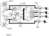
- the AC electrical network further comprises first and second further bi-directional AC-DC converters 224a, 224b are provided.
- Each of the further bi-directional AC-DC converters 224a, 224b are operable to convert AC power from a respective AC electrical network 216a, 216b to DC power for the battery 222, and are operable to convert DC power from the battery 222 to AC power for the respective AC electrical networks 216a, 216b.
- both generators can fail, yet power can still be provided to both the directly connected motors 219a, 219b, and the indirectly connected propulsors 219c, 219d.
- power can still be transferred between the AC electrical networks 216a, 216b in the event of a failure of one of the bi-directional converters 217a, 217b.
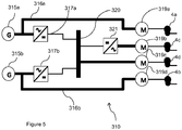
- Figure 5 shows a shows a fourth electrical network 110 in accordance with the present disclosure, which is suitable for use in an aircraft similar to that shown in figure 1 .
- the system 310 comprises first and second AC generators 315a, 315b.
- the AC generators 315a, 315b are asynchronous inductance generators, which provide AC electrical power having a frequency that is not directly proportional to their rotational speed, since there is a degree of "slip" between the rotating magnetic field and the electrical energy induced in the stator coils.
- Each generator 315a, 315b is electrically coupled to a respective AC network 316a, 316b, which comprises a respective AC / DC converter 317a, 317b.
- the converters 317a, 317b differ from those in previous embodiments, in that the converters are one way only, i.e. they are only required to convert AC electrical power from the AC electrical network 316, 316b to DC power for a DC network 318.
- the DC network 318 comprises an inverter 321 which is coupled via a DC electrical bus 320.
- Directly coupled AC motors 319a, 319b are coupled to the AC networks 316a, 316b, and further motors 319c, 319d are coupled to the DC network 320.
- the directly coupled first and second motors 219a, 219b differ from those of other embodiments, in that they comprise asynchronous AC motors, such as squirrel cage inductance motors, which have a rotational frequency that may differ from the AC power frequency.
- a first further AC motor 319b is indirectly coupled to the DC electrical 320 via the inverter 321. Again, the first further AC motor 319b may comprise a synchronous motor or an asynchronous motor.
- a second further motor 318c is directly coupled to the DC electrical network 320, and comprises a DC electrical motor, such as a brushed or brushless electrical motor.
- thrust control of the propulsors 4a-d can be provided, whilst maintaining the gas turbine engines and generators 315a, 315b at a constant speed, whilst also providing an efficient lightweight system in view of the high energy efficiency of AC generators and motors.
- gas turbine engines to which the present disclosure may be applied may have alternative configurations.
- such engines may have an alternative number of interconnecting shafts (e.g. two) and/or an alternative number of compressors and/or turbines.
- the engine may comprise a gearbox provided in the drive train from a turbine to a compressor and/or generator.
- Each generator may be directly coupled to the respective gas turbine engine main shaft, or may be coupled via a bevel drive.
- the generator may be indirectly coupled to the gas turbine engine, such as through torque converter or continuously variable transmission.
- the generators may be driven by alternative means, such as reciprocating diesel or petrol engines.
- the propellers could have a fixed pitch.
- the energy storage device could comprise a fuel cell.
- the propellers may be installed on different parts of the aircraft.
- the indirectly coupled motors may be provided further from the generators than the directly coupled motors. Since DC cables generally have a lower mass than AC cables, a reduction in overall weight may be achieved. Consequently, the indirectly coupled motors may be located at the tail of the aircraft, and may be configured to ingest boundary layer air.
- the gas turbine engines may further comprise one or more mechanically driven fans configured to act as propulsors. Consequently, the electrically driven propulsors may only provide a part of the propulsive power of the aircraft.
- the invention has been described in relation to an aircraft propulsion system, it will be appreciated that the invention is equally applicable to other vehicles, such as land vehicles, ships and submarines.
- the vehicle is an aircraft
- the aircraft may comprise a fixed wing aircraft or a vertical takeoff aircraft such as a helicopter.
- the aircraft may be manned or unmanned.
- the motors may be re-synchronised to the AC input power by an alternative method, such as one or more of:
Abstract
Description
- The present disclosure concerns an aircraft propulsion system, an aircraft comprising the propulsion system, and a method of operating the aircraft propulsion system.
- There is a continuing need for more efficient aircraft designs, in terms of structural efficiency (i.e. minimising the overall weight of the aircraft structure), aerodynamic efficiency (i.e. minimising the aerodynamic drag incurred during flight) and fuel efficiency (i.e. minimising the fuel required to perform a particular aircraft mission). One solution for increasing aircraft efficiency is to provide an aircraft driven by a hybrid mechanical-electrical propulsion system.
- In a hybrid mechanical-electrical propulsion system, a generator driven by, for example, an internal combustion engine, is employed to produce electrical power. This electrical power is provided to one or more propulsors, such as electric fans which may be distributed about the aircraft, remote from the electrical generator.
- "Distributed Turboelectric Propulsion for Hybrid Wing Body Aircraft" by Hyun Dae Kim, Gerald V Brown and James L Felder, published by the Royal Aeronautical Society, describes a number of distributed propulsion systems and aircraft concepts. This document describes concepts in which a relatively large number of electrically driven propulsors are powered by a relatively small number of internal combustion engines.
- Similarly,
US2015/0367950 discloses a system in which a gas turbine engine drives an electrical generator. Power is distributed through an electrical network to a plurality of electrical motors, which drives propulsive fans. - Similar problems apply to other vehicle types, such as motor vehicles, marine vehicles etc.
- Accordingly, the present disclosure seeks to provide a vehicle propulsion system which is efficient, lightweight, low cost and controllable.
- According to a first aspect there is provided a vehicle propulsion system comprising:
- at least first and second electrical generators, each being configured to provide AC electrical power to a respective first and second AC electrical network;
- at least first and second AC electrical motors directly electrically coupled to a respective AC network and coupled to a respective propulsor; and
- a DC electrical network electrically coupled to the first and second AC networks via respective first and second AC to DC converters, and to a further electrical motor, the further electrical motor being coupled to a propulsor.
- Advantageously, the first and second directly electrically coupled motors efficiently provide propulsive thrust in view of the low losses provided by wholly AC electrical systems, while thrust control can be provided utilising the one or more electrical motors coupled to the DC electrical network, without requiring either power electronics or control of the frequency of the AC networks. Consequently, the invention provides an efficient yet controllable aircraft propulsion system.
- One or more AC electrical generator may comprise a synchronous AC generator such as a permanent magnet or wound field synchronous generator or an asynchronous electrical generator such as an induction generator. One or more AC electrical motor may comprise one or more of a synchronous AC motor such as a permanent magnet or wound field synchronous motor or an asynchronous electrical motor such as an induction motor.
- The first and / or second AC to DC converters may comprise bi-directional AC to DC converters configured to provide AC electrical power from the AC network to DC electrical power to the DC network, and DC electrical power from the DC network to AC electrical power to the AC electrical network.
- Advantageously, in the event that one of the synchronous AC electric motors coupled to the AC electrical network loses synchronisation with the AC electrical network, the motor can be re-synchronised. This can be achieved without requiring a dedicated inverter for each electric motor, thereby saving weight and reducing electrical losses in normal operation.
- The further electrical motor may comprise one or more of a DC electrical motor directly electrically coupled to the DC electrical network, and an AC electrical motor coupled to the DC electrical network via a DC to AC inverter.
- A plurality of further AC electrical motors coupled to the DC electrical network may be provided. The inverter may be electrically coupled to the plurality of AC electrical motors, or a separate inverter may be provided for each electrical motor coupled to the DC electrical network.
- The system may comprise a controller configured to control the first and second bi-directional AC-DC converters between:
- a first operating mode, in which both the first and second AC-DC converters convert AC power from the respective AC networks to DC power to power to the DC network;
- a second operating mode, in which the first AC-DC converter converts AC power from the first AC network to DC power to power the DC network, and the second AC-DC converter converts DC power from the DC network to AC power to power the second AC electrical network; and
- a third operating mode, in which the second AC-DC converter converts AC power from the second AC network to DC power to power the DC network, and the first AC-DC converter converts DC power from the DC network to AC power to power the first AC electrical network.
- Advantageously, the controller can re-route power in the event of failure of an electrical component.
- The controller may be configured to switch from the first operating mode to the second or third operating mode in the event of one or more of:
- the synchronous electrical motor directly coupled to the first or second electrical network becoming de-synchronised from the respective AC network; and
- a failure of the first or second electrical generator.
- The first and second generators may be driven by an internal combustion engine such as a gas turbine engine. Each electrical generator may be driven by a separate internal combustion engine, or may be driven by the same internal combustion engine, and may be driven by a separate independently rotatable shaft of the same gas turbine engine.
- The system may comprise an energy storage device such as one or more of a battery, a capacitor and a hydrogen fuel cell electrically coupled to the DC electrical network, the energy storage device being configured to provide electrical power to the DC network in a discharging mode, and to receive electrical power from the DC network in a charging mode.
- The system may comprise a further bi-directional AC-DC converter electrically coupled to at least one of the first and second AC networks and the energy storage device, and configured to provide electrical power from the energy storage device to the or each AC network in a discharging mode, and to receive electrical power from the DC network in a charging mode.
- According to a second aspect there is provided an aircraft comprising the electrical network of the first aspect.
- The skilled person will appreciate that except where mutually exclusive, a feature described in relation to any one of the above aspects may be applied mutatis mutandis to any other aspect. Furthermore except where mutually exclusive any feature described herein may be applied to any aspect and/or combined with any other feature described herein.
- Embodiments will now be described by way of example only, with reference to the Figures, in which:
-
Figure 1 is a plan view of an aircraft in accordance with the present disclosure; -
Figure 2 is a schematic of a propulsion system for the aircraft offigure 1 ; -
Figure 3 is a schematic of an alternative propulsion system for the aircraft offigure 1 ; -
Figure 4 is a schematic of a further alternative propulsion system for the aircraft offigure 1 ; and -
Figure 5 is a schematic of a still further alternative propulsion system for the aircraft offigure 1 . - With reference to
Figure 1 , anaircraft 1 is described, comprising apropulsion system 10. Theaircraft 1 comprises afuselage 2,wings 3 and vertical 7 and horizontal 8 control surfaces. Theaircraft 1 is powered by propulsors in the form ofpropellers 4 provided on wing mountedpods 5. In this embodiment, theengines 4 are mounted such thatpropellers 5 are located forward of thewing 2 and either side of thefuselage 2. - The aircraft comprises at least one
gas turbine engine 6, with the described embodiment having agas turbine engine 6 mounted on eachwing 2, toward a respective tip. - Referring to
figure 2 , part of thepropulsion system 10 is shown schematically. The part of thepropulsion system 10 shown infigure 2 represents the propulsion system for thepropellers 4 of one of thewings 3, with a corresponding further part of the propulsion system provided on theother wing 3. Eachgas turbine engine 6 comprises acompressor 11,combustor 12 andturbine 13. Thecompressor 11 andturbine 13 are interconnected by ashaft 14, such that rotation of the turbine in use causes rotation of thecompressor 11. - The
shaft 13 of eachgas turbine engine 6 is also coupled to a respective rotor (not shown) of first and second synchronous alternating current (AC)electrical generators shaft 14 causes rotation of each of thecompressor 11,turbine 13 and the rotors of bothgenerators 15a, 15, which thereby generate AC electrical power having a frequency proportional to the rotational speed of theshaft 14. It will be understood that the frequency will also be dependent on the number of poles of the stators (not shown) of the respectiveelectrical generators - Each
generator second AC networks figures 2 to 4 . Consequently, eachelectrical network respective AC generator second AC networks second generators gas turbine engine 6 could comprise multiple shafts interconnecting different compressors and turbines, and thegenerators second generators gas turbine engines 6, which could be operated at different speeds. - The
AC networks electrical motors motors respective AC network respective generator generators networks motors - Each directly coupled
electric motor respective propeller electric motors respective propellers turbine engine shaft 14 is used to generate AC electrical power by thegenerators electrical motors AC networks propellers - The electrical network further comprises first and second bi-directional AC/
DC converters electrical networks converter electrical network 18. - Each
converter respective AC network electrical network 18, whilst also managing ripple frequency. In the DC to AC conversion mode, power from theDC network 18 is converted to AC electrical power, and provided to the respective ACelectrical network converters generators AC networks DC network 18. - The
DC network 18 further comprises an energy storage device in the form of a battery 22, which is coupled to the DC network via a DC-DC converter 23 configured to operate in a discharging mode, in which the battery discharges power provided to theDC network 18, and a charging mode, in which the battery is charged with power from theDC network 18. The DC-DC converter ensures that power from the battery 22 is provided to the DC network at the correct voltage, and controls the voltage to the battery to control charging. - The DC
electrical network 18 comprises first, second andthird DC buses first bus 20a is connected to thefirst converter 17a, thesecond bus 20b, thethird bus 20c, and afirst inverter 21 a by respective connectors. Thesecond bus 20b is connected to the battery 22 via the DC-DC converter 23, and to thethird bus 20c. The third bus is connected to thesecond converter 17b, and to asecond inverter 21 b. Switches are provided, for selectively making and breaking contacts between thecomponents - Each
inverter motor - The
motors inverters 21 a, 2b, the frequency of the supply current to eachmotors AC generators motors motors respective propeller motors - The
propulsion system 10 can be operated in one of three distinct operating modes. In a first mode, bothgenerators converters DC converter 23 may be in either a charging or discharging mode, depending on the state of charge of the battery, and electrical power requirements of themotors 19a-d. At least the switches interconnecting theconverter 17a andinverter 21 a, and theconverter 17b andinverter 21b are closed. Consequently, AC electrical power at the generator frequency is provided to the directly coupledmotors converters DC network 18, and is sent to theinverters generators - Thrust control can be provided in the first mode as follows. Where increased thrust is required, the
motors motor controllers generators turbine engine shaft 14, and so the rotational speed of both thecompressor 11 andturbine 13. An engine controller (not shown) may detect this reduced rotational speed, and increase fuel flow to thecombustor 12, to thereby maintain rotational speed of the engine at the nominal level. A reduction in thrust can be provided by reducing the load on thepropellers motors - In accordance with the above, thrust control can be provided more rapidly than could be provided by ramping up and down the gas turbine rotational speed alone. Furthermore, since the gas turbine engine is operated at a constant rotational speed during most operation, the compressors and turbines can be designed for a single operating point, thereby increasing efficiency. On the other hand, where very low thrust is required, the
gas turbine engine 6 can be throttled down to a lower rotational speed, to thereby reduce the rotational speed of the directly coupledpropellers propellers - In a second operating mode of the propulsion system, the
system 10 can be operated as follows. Thefirst converter 17a is operated in the AC to DC conversion mode, while thesecond converter 17b is operated in the DC to AC converter mode. Consequently, power from thefirst AC network 16a is re-routed through theDC network 18, to the second AC network 16b. Power transfer may be supplemented from the battery 22. Meanwhile, power may continue to be transferred to the in-directly coupledmotors second AC network 16b. - Consequently, in the event that
generator 15b fails, the remaininggenerator 15a can be utilised to provide electrical power to all of themotors 19a-d, and therefore to all of thepropellers 4a-d. Furthermore, in the event that the directly drivenelectrical motor 19b becomes de-synchronised with the ACelectrical network 16b (such as due to a bird strike or a power transient), re-synchronisation can be achieved by transferring power from thefirst AC network 16a to thesecond network 16b. - In a third operating mode, the system is operated with the
first converter 17a operated in the DC to AC conversion mode, and thesecond converter 17b operated in the AC to DC conversion mode. Again therefore, power is re-routed, this time from the second 16b to thefirst AC network 16a. - Furthermore, a degree of redundancy is provided, since, in the event of one of the
converters motors -
Figure 3 shows a secondelectrical network 110 in accordance with the present disclosure, which is suitable for use in an aircraft similar to that shown infigure 1 . - Again, the system comprises first and second AC
synchronous generators generators generator gas turbine engine generator respective AC network DC converter converters inverters DC buses 120a-c. Directly coupled ACsynchronous motors AC networks motors 119c, 119d are coupled to theinverters - This embodiment differs from the first embodiment in that further directly coupled
motors 119e-h are provided. Consequently, a total of six directly coupled motors are provided, compared to two indirectly coupled motors. Consequently, a narrower band of thrust can be controlled using the motor controllers. However, this may be sufficient to provide short term, small throttle changes, with larger thrust changes being made by adjusting the rotational speed of theengines -
Figure 3 shows a thirdelectrical network 110 in accordance with the present disclosure, which is suitable for use in an aircraft similar to that shown infigure 1 . - Again, the system comprises first and second AC
synchronous generators generators generator respective AC network DC converter converters electrical bus 220. Directly coupled ACsynchronous motors AC networks motors battery 222 and DC-DC converter is also provided in electrical contact with the DC network 218. - This embodiment further differs from the previous embodiments in that the AC electrical network further comprises first and second further bi-directional AC-
DC converters DC converters electrical network battery 222, and are operable to convert DC power from thebattery 222 to AC power for the respective ACelectrical networks motors propulsors electrical networks bi-directional converters -
Figure 5 shows a shows a fourthelectrical network 110 in accordance with the present disclosure, which is suitable for use in an aircraft similar to that shown infigure 1 . - The
system 310 comprises first andsecond AC generators 315a, 315b. in this embodiment, theAC generators - Each
generator respective AC network DC converter converters electrical network 316, 316b to DC power for a DC network 318. - The DC network 318 comprises an
inverter 321 which is coupled via a DCelectrical bus 320. Directly coupledAC motors AC networks further motors DC network 320. Again, in this case the directly coupled first andsecond motors further AC motor 319b is indirectly coupled to the DC electrical 320 via theinverter 321. Again, the firstfurther AC motor 319b may comprise a synchronous motor or an asynchronous motor. A second further motor 318c is directly coupled to the DCelectrical network 320, and comprises a DC electrical motor, such as a brushed or brushless electrical motor. - In this embodiment, thrust control of the
propulsors 4a-d can be provided, whilst maintaining the gas turbine engines andgenerators - It will be understood that the invention is not limited to the embodiments above-described and various modifications and improvements can be made without departing from the concepts described herein. Except where mutually exclusive, any of the features may be employed separately or in combination with any other features and the disclosure extends to and includes all combinations and subcombinations of one or more features described herein.
- For example, other gas turbine engines to which the present disclosure may be applied may have alternative configurations. By way of example such engines may have an alternative number of interconnecting shafts (e.g. two) and/or an alternative number of compressors and/or turbines. Further the engine may comprise a gearbox provided in the drive train from a turbine to a compressor and/or generator.
- Each generator may be directly coupled to the respective gas turbine engine main shaft, or may be coupled via a bevel drive. Alternatively, the generator may be indirectly coupled to the gas turbine engine, such as through torque converter or continuously variable transmission. The generators may be driven by alternative means, such as reciprocating diesel or petrol engines. The propellers could have a fixed pitch. The energy storage device could comprise a fuel cell. The propellers may be installed on different parts of the aircraft. For example, the indirectly coupled motors may be provided further from the generators than the directly coupled motors. Since DC cables generally have a lower mass than AC cables, a reduction in overall weight may be achieved. Consequently, the indirectly coupled motors may be located at the tail of the aircraft, and may be configured to ingest boundary layer air.
- As a further alternative, the gas turbine engines may further comprise one or more mechanically driven fans configured to act as propulsors. Consequently, the electrically driven propulsors may only provide a part of the propulsive power of the aircraft.
- Although the invention has been described in relation to an aircraft propulsion system, it will be appreciated that the invention is equally applicable to other vehicles, such as land vehicles, ships and submarines. Where the vehicle is an aircraft, the aircraft may comprise a fixed wing aircraft or a vertical takeoff aircraft such as a helicopter. The aircraft may be manned or unmanned.
- Similarly, it will be understood that, where the electrical motors are synchronous electrical motors, the motors may be re-synchronised to the AC input power by an alternative method, such as one or more of:
- PWM (pulse width modulation) control;
- mechanical speed control of the motor or associated propeller, such as by a clutch, brake, or slave magnetic brake;
- voltage or current control;
- phase or phase angle control;
- switchgears or electronic switching;
- disconnection of the motor/generator from the converter for a given period of time;
- use of the converter to vary the speed of the motor/generator to reach synchronism; and
- reconnection of the motor/generator to the rest of the network once synchronism has been achieved through dropping speed, frequency, power.
Claims (14)
- A vehicle propulsion system (10) comprising:at least first and second electrical generators (15a, 15b), each being configured to provide electrical power to a respective first and second AC electrical network (16a, 16b);at least first and second AC electrical motors (19a, 19b) directly electrically coupled to a respective AC network (16a, 16b) and coupled to a respective propulsor (4); anda DC electrical network (18) electrically coupled to the first and second AC networks (16a, 16b) via respective first and second AC to DC converters (17a, 17b), and to a further electrical motor (19c, 19d), the further electrical motor (19c) being coupled to a propulsor (4).
- A system according to claim 1, wherein each AC electrical generator (15a, 15b) comprises a synchronous AC generator such as a permanent magnet or wound field synchronous generator.
- A system according to claim 1, wherein each AC electrical generator comprises an asynchronous electrical generator (315a, 315b) such as an induction generator.
- A system according to any of the preceding claims wherein one or more AC electrical motor (19a, 19b) comprises a synchronous AC motor such as a permanent magnet or wound field synchronous motor.
- A system according to any of the preceding claims, wherein one or more AC electrical motor comprises an asynchronous electrical motor (219a, 219b) such as an induction motor.
- A system according to any of the preceding claims, wherein the first and / or second AC to DC converters (17a, 17b) comprise bi-directional AC to DC converters configured to provide AC electrical power from the AC network (16a, 16b) to DC electrical power to the DC network (18), and DC electrical power from the DC network (18) to AC electrical power to the AC electrical network (16a, 16b).
- A system according to any of the preceding claims, wherein the further electrical motor comprises one of an DC electrical motor (319d) directly electrically coupled to the DC electrical network (18), and an AC electrical motor (19c, 19d) coupled to the DC electrical network (18) via a DC to AC inverter (21 a, 21 b).
- A system according to claim 6 or any claim dependent thereon, wherein the system comprises a controller configured to control the first and second bi-directional AC-DC converters (19a, 19b) between:a first operating mode, in which both the first and second AC-DC converters (19a, 19b) convert AC power from the respective AC networks (16a, 16b) to DC power to power to the DC network (18);a second operating mode, in which the first AC-DC converter (19a) converts AC power from the first AC network (16a) to DC power to power the DC network (18), and the second AC-DC converter (19b) converts DC power from the DC network (18) to AC power to power the second AC electrical network (16b); anda third operating mode, in which the second AC-DC converter (19b) converts AC power from the second AC network (16b) to DC power to power the DC network (18), and the first AC-DC converter (19a) converts DC power from the DC network (18) to AC power to power the first AC electrical network (16a).
- A system according to claim 8 when dependent on claim 4, wherein the controller is configured to switch from the first operating mode to the second or third operating mode in the event of one or more of:the synchronous electrical motor (19a, 19b) directly coupled to the first or second AC electrical network (16a, 16b) becoming de-synchronised from the respective AC network (16a, 16b); anda failure of the first or second electrical generator (15a, 15b).
- A system according to any of the preceding claims wherein the first and second generators (15a, 15b) are driven by an internal combustion engine such as a gas turbine engine (6).
- A system according to any of the preceding claims, wherein the system comprises an energy storage device (22) such as one or more of a battery, a capacitor and a hydrogen fuel cell electrically coupled to the DC electrical network (18), the energy storage (22) device being configured to provide electrical power to the DC network (18) in a discharging mode, and to receive electrical power from the DC network (18) in a charging mode.
- A system according to claim 11, wherein the system comprises a further bi-directional AC-DC converter electrically coupled to at least one of the first and second AC networks and the energy storage device, and configured to provide electrical power from the energy storage device to the or each AC network in a discharging mode, and to receive electrical power from the DC network in a charging mode.
- A vehicle (1) comprising the propulsion system (10) of any of the preceding claims.
- A vehicle according to claim 13, wherein the vehicle comprises an aircraft (1).
Applications Claiming Priority (1)
| Application Number | Priority Date | Filing Date | Title |
|---|---|---|---|
| GBGB1615900.6A GB201615900D0 (en) | 2016-09-19 | 2016-09-19 | Aircraft propulsion system |
Publications (2)
| Publication Number | Publication Date |
|---|---|
| EP3296212A1 true EP3296212A1 (en) | 2018-03-21 |
| EP3296212B1 EP3296212B1 (en) | 2019-03-27 |
Family
ID=57288709
Family Applications (1)
| Application Number | Title | Priority Date | Filing Date |
|---|---|---|---|
| EP17187444.9A Active EP3296212B1 (en) | 2016-09-19 | 2017-08-23 | Aircraft propulsion system |
Country Status (3)
| Country | Link |
|---|---|
| US (2) | US10974836B2 (en) |
| EP (1) | EP3296212B1 (en) |
| GB (1) | GB201615900D0 (en) |
Cited By (23)
| Publication number | Priority date | Publication date | Assignee | Title |
|---|---|---|---|---|
| FR3079210A1 (en) * | 2018-03-26 | 2019-09-27 | Safran | PROPULSIVE MULTIROTOR AIRCRAFT SYSTEM WITH RECONFIGURABLE ELECTRICAL SYSTEM |
| FR3083778A1 (en) * | 2018-07-16 | 2020-01-17 | Safran Electrical & Power | NON-PROPULSIVE ELECTRICAL PROPULSION AND GENERATION SYSTEM FOR A MULTI-ROTOR AIRCRAFT, AND ASSOCIATED AIRCRAFT |
| EP3620383A1 (en) * | 2018-09-06 | 2020-03-11 | Pratt & Whitney Canada Corp. | Hybrid electric aircraft propulsion system and method |
| FR3085667A1 (en) * | 2018-09-12 | 2020-03-13 | Safran | HYBRID PROPELLENT ASSEMBLY SERIES FOR AIRCRAFT |
| FR3087960A1 (en) * | 2018-10-31 | 2020-05-01 | Safran | ELECTRIC POWER CONVERSION AND TRANSPORT SYSTEM FOR INTERNAL HYBRIDIZATION OF A TURBO-AIRCRAFT AIRCRAFT |
| EP3703220A1 (en) * | 2019-03-01 | 2020-09-02 | The Boeing Company | Active voltage control for hybrid electric aircraft |
| WO2020201639A1 (en) | 2019-04-02 | 2020-10-08 | Safran Helicopter Engines | Hybrid propulsion unit for an aircraft |
| FR3095415A1 (en) * | 2019-04-26 | 2020-10-30 | Safran Helicopter Engines | PROPULSION SYSTEM FOR MULTI-ROTOR AIRCRAFT WITH NETWORK OF RECONFIGURABLE ELECTRICAL ENERGY STORAGE UNITS |
| EP3825229A1 (en) * | 2019-11-19 | 2021-05-26 | AIRBUS HELICOPTERS DEUTSCHLAND GmbH | Propulsion system for an electrically driven aircraft, aircraft comprising a propulsion system and method of selectively adapting an energy supply within a propulsion system of an electrically driven aircraft |
| WO2021064388A3 (en) * | 2019-10-02 | 2021-06-24 | Electric Aviation Group Ltd | Systems and methods for aircraft |
| EP3848287A1 (en) * | 2020-01-07 | 2021-07-14 | Hamilton Sundstrand Corporation | Electric propulsion system |
| WO2021198585A1 (en) * | 2020-04-01 | 2021-10-07 | Safran | Propulsion system for fixed-wing aircraft, and associated aircraft |
| WO2021209701A1 (en) * | 2020-04-15 | 2021-10-21 | Safran | Propulsion channel for aircraft |
| FR3118622A1 (en) * | 2021-01-06 | 2022-07-08 | Ascendance Flight Technologies | Hybrid Power Source Aircraft |
| EP4039524A1 (en) * | 2021-02-09 | 2022-08-10 | Aurora Flight Sciences Corporation, a subsidiary of The Boeing Company | Fault-tolerant power distribution in a vehicle |
| DE102021106648A1 (en) | 2021-03-18 | 2022-09-22 | Rolls-Royce Deutschland Ltd & Co Kg | System and method for simulating different aircraft configurations with an electric aircraft |
| EP4195493A1 (en) * | 2021-12-07 | 2023-06-14 | Hamilton Sundstrand Corporation | Parallel excitation of motor start function for three stage synchronous generator |
| FR3131279A1 (en) * | 2021-12-23 | 2023-06-30 | Safran | Electric propulsion chain of an aircraft |
| EP4239878A1 (en) * | 2022-03-02 | 2023-09-06 | Rolls-Royce plc | Electric aircraft propulsion assembly and method |
| US11757386B2 (en) | 2018-09-06 | 2023-09-12 | Pratt & Whitney Canada Corp. | Hybrid electric propulsion system and method of operation |
| WO2023198998A1 (en) | 2022-04-15 | 2023-10-19 | Ascendance Flight Technologies | Aircraft having a hybrid power source |
| FR3136907A1 (en) * | 2022-06-21 | 2023-12-22 | Safran Electrical & Power | Electrical distribution system for aircraft and associated method |
| WO2024009028A1 (en) * | 2022-07-08 | 2024-01-11 | Safran Electrical & Power | Electrical propulsion chain for an aircraft and method for charging a battery of an aircraft |
Families Citing this family (34)
| Publication number | Priority date | Publication date | Assignee | Title |
|---|---|---|---|---|
| CN107112928B (en) * | 2014-12-17 | 2021-01-15 | 奥的斯电梯公司 | Conveyor system with parallel drives |
| US10227137B2 (en) * | 2016-03-22 | 2019-03-12 | Ge Aviation Systems Llc | Hybrid power system for an aircraft |
| US10730633B2 (en) * | 2016-11-22 | 2020-08-04 | Honeywell International Inc. | Hybrid electric aircraft propulsion system with motors using induction effect |
| US10689082B2 (en) * | 2017-04-12 | 2020-06-23 | Rolls-Royce North American Technologies, Inc. | Mechanically and electrically distributed propulsion |
| US11008111B2 (en) * | 2017-06-26 | 2021-05-18 | General Electric Company | Propulsion system for an aircraft |
| US10822101B2 (en) * | 2017-07-21 | 2020-11-03 | General Electric Company | Vertical takeoff and landing aircraft having a forward thrust propulsor |
| US10483886B2 (en) * | 2017-09-14 | 2019-11-19 | Hamilton Sundstrand Corportion | Modular electric power generating system with multistage axial flux generator |
| US11214378B2 (en) * | 2018-08-21 | 2022-01-04 | Zunum Aero, Inc. | System controller for series hybrid powertrain |
| GB201814869D0 (en) * | 2018-09-03 | 2018-10-31 | Rolls Royce Plc | Aircraft Propulsion System |
| US11233470B2 (en) | 2018-09-06 | 2022-01-25 | Pratt & Whitney Canada Corp. | Synchronization of generator and electric motor in a hybrid electric aircraft propulsion system |
| FR3086923B1 (en) * | 2018-10-04 | 2020-11-06 | Safran | ELECTRICAL ARCHITECTURE FOR HYBRID PROPULSION |
| US11370554B2 (en) | 2018-11-08 | 2022-06-28 | Rolls-Royce North American Technologies, Inc. | Hybrid propulsion systems |
| US11225881B2 (en) | 2018-11-08 | 2022-01-18 | Rolls-Royce North American Technologies, Inc. | Hybrid propulsion systems |
| US10759540B2 (en) * | 2018-11-08 | 2020-09-01 | Rolls-Royce North American Technologies, Inc. | Hybrid propulsion systems |
| US11159024B2 (en) | 2018-11-08 | 2021-10-26 | Rolls-Royce North American Technologies, Inc. | Electrical architecture for hybrid propulsion |
| US11312503B1 (en) | 2018-12-17 | 2022-04-26 | Zunum Aero, Inc. | Systems and methods for implementing lightweight and reliable hybrid or electric powertrains for aircraft |
| FR3095195B1 (en) * | 2019-04-17 | 2021-05-07 | Safran Helicopter Engines | PROCEDURE FOR CONTROLLING AN AIRCRAFT ELECTRICAL POWER SUPPLY NETWORK |
| GB2588792A (en) * | 2019-11-07 | 2021-05-12 | Rolls Royce Plc | Electrical power supply system |
| GB2590953A (en) | 2020-01-09 | 2021-07-14 | Rolls Royce Plc | Torsional mode damping controller |
| US11514732B2 (en) | 2020-02-27 | 2022-11-29 | Rolls-Royce Corporation | Electrical machine monitor |
| US11661201B2 (en) * | 2020-03-19 | 2023-05-30 | Ohio State Innovation Foundation | Independent speed variable frequency generator for more electric aircraft using brushless doubly-fed machines (BDFM) |
| US20220063819A1 (en) * | 2020-08-31 | 2022-03-03 | General Electric Company | Propulsion system for an aircraft |
| FR3118337A1 (en) * | 2020-12-18 | 2022-06-24 | Airbus Operations (S.A.S.) | Aircraft with electric or hybrid propulsion comprising a suitable electrical installation |
| US11196585B1 (en) | 2021-03-31 | 2021-12-07 | Beta Air, Llc | Method and system for virtualizing a plurality of controller area network bus units communicatively connected to an aircraft |
| WO2022212422A1 (en) * | 2021-03-31 | 2022-10-06 | Zeroavia Ltd. | Multiple energy source management system |
| US11447015B1 (en) | 2021-06-15 | 2022-09-20 | Beta Air, Llc | System and method for dynamic excitation of an energy storage element configured for use in an electric aircraft |
| US20230058484A1 (en) * | 2021-08-17 | 2023-02-23 | Pratt & Whitney Canada Corp. | Nested control loop structure for hybrid propulsion system |
| US11670942B2 (en) * | 2021-09-23 | 2023-06-06 | General Electric Company | Electrically driven distributed propulsion system |
| JP2023147342A (en) * | 2022-03-30 | 2023-10-13 | 本田技研工業株式会社 | Control device of aircraft |
| US11634232B1 (en) * | 2022-04-30 | 2023-04-25 | Beta Air, Llc | Hybrid propulsion systems for an electric aircraft |
| US11639230B1 (en) * | 2022-04-30 | 2023-05-02 | Beta Air, Llc | System for an integral hybrid electric aircraft |
| US11691745B1 (en) | 2022-04-30 | 2023-07-04 | Beta Air, Llc | Systems and methods for locking an electric propulsion system |
| US20240017823A1 (en) * | 2022-07-18 | 2024-01-18 | Textron Innovations Inc. | Optimizing usage of supplemental engine power |
| DE102022119116A1 (en) | 2022-07-29 | 2024-02-01 | MTU Aero Engines AG | DRIVE SYSTEM FOR AN AIRCRAFT |
Citations (5)
| Publication number | Priority date | Publication date | Assignee | Title |
|---|---|---|---|---|
| EP1029783A2 (en) * | 1999-02-16 | 2000-08-23 | Electric Boat Corporation | Marine power distribution arrangement |
| EP2192681A1 (en) * | 2008-11-26 | 2010-06-02 | Siemens Aktiengesellschaft | Power distribution system and method thereof |
| US20110080040A1 (en) * | 2009-10-02 | 2011-04-07 | Ajith Kuttannair Kumar | Power generation apparatus |
| WO2014158240A2 (en) * | 2013-03-14 | 2014-10-02 | Rolls-Royce Corporation | Hybrid turbo electric aero-propulsion system control |
| EP2995555A1 (en) * | 2014-09-02 | 2016-03-16 | Hamilton Sundstrand Corporation | Propulsion system |
Family Cites Families (21)
| Publication number | Priority date | Publication date | Assignee | Title |
|---|---|---|---|---|
| US7540450B2 (en) | 2004-07-16 | 2009-06-02 | Pratt & Whitney Canada Corp. | Aircraft propulsion system |
| FR2898871B1 (en) | 2006-03-24 | 2009-02-06 | Airbus France Sas | SYSTEM AND METHOD FOR POWER SUPPLYING USER SYSTEMS ABOARD AN AIRCRAFT |
| GB2443002A (en) | 2006-10-16 | 2008-04-23 | Converteam Ltd | dc power distribution system |
| GB0903423D0 (en) | 2009-03-02 | 2009-04-08 | Rolls Royce Plc | Variable drive gas turbine engine |
| GB0911100D0 (en) | 2009-06-29 | 2009-08-12 | Rolls Royce Plc | Propulsive fan system |
| US8355855B2 (en) | 2010-05-21 | 2013-01-15 | General Electric Company | Systems and methods for controlling an integrated drive train |
| GB201015760D0 (en) | 2010-09-21 | 2010-10-27 | Airbus Uk Ltd | Aircraft power distribution network |
| FR2975547B1 (en) | 2011-05-20 | 2013-06-07 | Turbomeca | METHOD FOR RATIONALIZING CHAIN OF ELECTRICAL COMPONENTS OF AN AIRCRAFT, IMPLEMENTING ARCHITECTURE AND CORRESPONDING AIRCRAFT |
| FR2978728B1 (en) | 2011-08-03 | 2014-07-04 | Eads Europ Aeronautic Defence | AIRCRAFT PROPULSION ARCHITECTURE INTEGRATING AN ENERGY RECOVERY SYSTEM |
| GB2497136A (en) | 2011-12-02 | 2013-06-05 | Eads Uk Ltd | Electric distributed propulsion |
| DE102012209807A1 (en) | 2012-06-12 | 2013-12-12 | Siemens Aktiengesellschaft | Airplane and method for manufacturing an aircraft |
| FR3000469B1 (en) | 2013-01-03 | 2014-12-19 | Microturbo | METHOD FOR MANAGING THE ELECTRIC POWER SUPPLY NETWORK OF AN AIRCRAFT |
| EP2969761B1 (en) | 2013-03-14 | 2020-04-01 | Rolls-Royce Corporation | Intelligent integrated propulsion control system and method |
| GB201308292D0 (en) * | 2013-05-09 | 2013-06-12 | Rolls Royce Plc | Aircraft electrical system |
| GB201320988D0 (en) | 2013-11-28 | 2014-01-15 | Rolls Royce Plc | An aircraft |
| FR3017258B1 (en) * | 2014-01-31 | 2016-01-15 | Hispano Suiza Sa | ELECTRICAL DISTRIBUTION AND CONVERSION SYSTEM FOR AN AIRCRAFT |
| FR3019214B1 (en) * | 2014-03-27 | 2019-05-31 | Safran Helicopter Engines | ASSISTANCE DEVICE FOR AN AIRCRAFT FREE TURBINE TURBINE |
| US9878796B2 (en) | 2014-03-27 | 2018-01-30 | United Technologies Corporation | Hybrid drive for gas turbine engine |
| FR3024606B1 (en) | 2014-08-01 | 2018-03-02 | Thales | ELECTRICAL NETWORK OF AN AIRCRAFT |
| US11271407B2 (en) * | 2016-04-07 | 2022-03-08 | Eaton Intelligent Power Limited | Power distribution system using AC/DC ring configuration |
| US20170291712A1 (en) * | 2016-04-08 | 2017-10-12 | Hamilton Sundstrand Corporation | Hybrid electric aircraft propulsion incorporating a recuperated prime mover |
-
2016
- 2016-09-19 GB GBGB1615900.6A patent/GB201615900D0/en not_active Ceased
-
2017
- 2017-08-23 US US15/684,265 patent/US10974836B2/en active Active
- 2017-08-23 EP EP17187444.9A patent/EP3296212B1/en active Active
-
2021
- 2021-03-10 US US17/197,708 patent/US11542021B2/en active Active
Patent Citations (5)
| Publication number | Priority date | Publication date | Assignee | Title |
|---|---|---|---|---|
| EP1029783A2 (en) * | 1999-02-16 | 2000-08-23 | Electric Boat Corporation | Marine power distribution arrangement |
| EP2192681A1 (en) * | 2008-11-26 | 2010-06-02 | Siemens Aktiengesellschaft | Power distribution system and method thereof |
| US20110080040A1 (en) * | 2009-10-02 | 2011-04-07 | Ajith Kuttannair Kumar | Power generation apparatus |
| WO2014158240A2 (en) * | 2013-03-14 | 2014-10-02 | Rolls-Royce Corporation | Hybrid turbo electric aero-propulsion system control |
| EP2995555A1 (en) * | 2014-09-02 | 2016-03-16 | Hamilton Sundstrand Corporation | Propulsion system |
Cited By (50)
| Publication number | Priority date | Publication date | Assignee | Title |
|---|---|---|---|---|
| CN111954622B (en) * | 2018-03-26 | 2023-08-04 | 赛峰集团 | Multi-rotor aircraft propulsion system with reconfigurable electrical network |
| WO2019186042A1 (en) * | 2018-03-26 | 2019-10-03 | Safran | Multi-rotor aircraft propulsion system with reconfigurable electric network |
| US11827374B2 (en) | 2018-03-26 | 2023-11-28 | Safran | Multi-rotor aircraft propulsion system with reconfigurable electric network |
| FR3079210A1 (en) * | 2018-03-26 | 2019-09-27 | Safran | PROPULSIVE MULTIROTOR AIRCRAFT SYSTEM WITH RECONFIGURABLE ELECTRICAL SYSTEM |
| CN111954622A (en) * | 2018-03-26 | 2020-11-17 | 赛峰集团 | Multi-rotor aircraft propulsion system with reconfigurable power network |
| FR3083778A1 (en) * | 2018-07-16 | 2020-01-17 | Safran Electrical & Power | NON-PROPULSIVE ELECTRICAL PROPULSION AND GENERATION SYSTEM FOR A MULTI-ROTOR AIRCRAFT, AND ASSOCIATED AIRCRAFT |
| WO2020016510A1 (en) * | 2018-07-16 | 2020-01-23 | Safran Electrical & Power | Multi-rotor aircraft comprising a system for propulsion and for non-propulsive electricity generation |
| US11312256B2 (en) | 2018-07-16 | 2022-04-26 | Safran Electrical & Power | Multi-rotor aircraft comprising a system for propulsion and for non-propulsive electricity generation |
| CN110877735A (en) * | 2018-09-06 | 2020-03-13 | 普拉特 - 惠特尼加拿大公司 | Synchronization of generator and motor in hybrid electric aircraft propulsion system |
| EP4037182A1 (en) * | 2018-09-06 | 2022-08-03 | Pratt & Whitney Canada Corp. | Hybrid electric aircraft propulsion system and method |
| EP3620384A1 (en) * | 2018-09-06 | 2020-03-11 | Pratt & Whitney Canada Corp. | Hybrid electric propulsion system and method of operation |
| EP3620383A1 (en) * | 2018-09-06 | 2020-03-11 | Pratt & Whitney Canada Corp. | Hybrid electric aircraft propulsion system and method |
| EP3620386A1 (en) * | 2018-09-06 | 2020-03-11 | Pratt & Whitney Canada Corp. | Hybrid electric aircraft propulsion system |
| EP3620385A1 (en) * | 2018-09-06 | 2020-03-11 | Pratt & Whitney Canada Corp. | Synchronization of generator and electric motor in a hybrid electric aircraft propulsion system |
| EP4152591A1 (en) * | 2018-09-06 | 2023-03-22 | Pratt & Whitney Canada Corp. | Hybrid electric propulsion system and method of operation |
| EP4224699A3 (en) * | 2018-09-06 | 2023-09-06 | Pratt & Whitney Canada Corp. | Synchronization of generator and electric motor in a hybrid electric aircraft propulsion system |
| US11757386B2 (en) | 2018-09-06 | 2023-09-12 | Pratt & Whitney Canada Corp. | Hybrid electric propulsion system and method of operation |
| WO2020053502A3 (en) * | 2018-09-12 | 2020-06-04 | Safran | Hybrid propulsion assembly for aircraft |
| US11932408B2 (en) | 2018-09-12 | 2024-03-19 | Safran | Hybrid propulsion assembly for aircraft |
| FR3085667A1 (en) * | 2018-09-12 | 2020-03-13 | Safran | HYBRID PROPELLENT ASSEMBLY SERIES FOR AIRCRAFT |
| WO2020089544A1 (en) * | 2018-10-31 | 2020-05-07 | Safran | System for converting and transporting electrical energy for the internal hybridisation of an aircraft with turbojet engines |
| FR3087960A1 (en) * | 2018-10-31 | 2020-05-01 | Safran | ELECTRIC POWER CONVERSION AND TRANSPORT SYSTEM FOR INTERNAL HYBRIDIZATION OF A TURBO-AIRCRAFT AIRCRAFT |
| US11945592B2 (en) | 2018-10-31 | 2024-04-02 | Safran | System for converting and transporting electrical energy for the internal hybridization of an aircraft with turbojet engines |
| EP3703220A1 (en) * | 2019-03-01 | 2020-09-02 | The Boeing Company | Active voltage control for hybrid electric aircraft |
| US20220177144A1 (en) * | 2019-04-02 | 2022-06-09 | Safran Helicopter Engines | Hybrid propulsion unit for an aircraft |
| FR3094697A1 (en) * | 2019-04-02 | 2020-10-09 | Safran Helicopter Engines | HYBRID PROPULSIVE INSTALLATION FOR AN AIRCRAFT |
| WO2020201639A1 (en) | 2019-04-02 | 2020-10-08 | Safran Helicopter Engines | Hybrid propulsion unit for an aircraft |
| FR3095415A1 (en) * | 2019-04-26 | 2020-10-30 | Safran Helicopter Engines | PROPULSION SYSTEM FOR MULTI-ROTOR AIRCRAFT WITH NETWORK OF RECONFIGURABLE ELECTRICAL ENERGY STORAGE UNITS |
| WO2021064394A3 (en) * | 2019-10-02 | 2021-07-08 | Electric Aviation Group Ltd | Systems and methods for aircraft |
| WO2021064388A3 (en) * | 2019-10-02 | 2021-06-24 | Electric Aviation Group Ltd | Systems and methods for aircraft |
| EP3825229A1 (en) * | 2019-11-19 | 2021-05-26 | AIRBUS HELICOPTERS DEUTSCHLAND GmbH | Propulsion system for an electrically driven aircraft, aircraft comprising a propulsion system and method of selectively adapting an energy supply within a propulsion system of an electrically driven aircraft |
| EP3848287A1 (en) * | 2020-01-07 | 2021-07-14 | Hamilton Sundstrand Corporation | Electric propulsion system |
| FR3108891A1 (en) * | 2020-04-01 | 2021-10-08 | Safran | Propulsion system for fixed-wing aircraft, and associated aircraft |
| WO2021198585A1 (en) * | 2020-04-01 | 2021-10-07 | Safran | Propulsion system for fixed-wing aircraft, and associated aircraft |
| WO2021209701A1 (en) * | 2020-04-15 | 2021-10-21 | Safran | Propulsion channel for aircraft |
| FR3109485A1 (en) * | 2020-04-15 | 2021-10-22 | Safran | Aircraft propulsion channel |
| FR3118622A1 (en) * | 2021-01-06 | 2022-07-08 | Ascendance Flight Technologies | Hybrid Power Source Aircraft |
| WO2022148926A1 (en) * | 2021-01-06 | 2022-07-14 | Ascendance Flight Technologies | Aircraft having a hybrid power source |
| US11715948B2 (en) | 2021-02-09 | 2023-08-01 | The Boeing Company | Fault-tolerant power distribution in a vehicle |
| EP4039524A1 (en) * | 2021-02-09 | 2022-08-10 | Aurora Flight Sciences Corporation, a subsidiary of The Boeing Company | Fault-tolerant power distribution in a vehicle |
| DE102021106648A1 (en) | 2021-03-18 | 2022-09-22 | Rolls-Royce Deutschland Ltd & Co Kg | System and method for simulating different aircraft configurations with an electric aircraft |
| EP4195493A1 (en) * | 2021-12-07 | 2023-06-14 | Hamilton Sundstrand Corporation | Parallel excitation of motor start function for three stage synchronous generator |
| FR3131279A1 (en) * | 2021-12-23 | 2023-06-30 | Safran | Electric propulsion chain of an aircraft |
| EP4239878A1 (en) * | 2022-03-02 | 2023-09-06 | Rolls-Royce plc | Electric aircraft propulsion assembly and method |
| WO2023198998A1 (en) | 2022-04-15 | 2023-10-19 | Ascendance Flight Technologies | Aircraft having a hybrid power source |
| FR3134562A1 (en) * | 2022-04-15 | 2023-10-20 | Ascendance Flight Technologies | Hybrid power source aircraft |
| WO2023247334A1 (en) * | 2022-06-21 | 2023-12-28 | Safran Electrical & Power | Electrical distribution system for aircraft and associated method |
| FR3136907A1 (en) * | 2022-06-21 | 2023-12-22 | Safran Electrical & Power | Electrical distribution system for aircraft and associated method |
| WO2024009028A1 (en) * | 2022-07-08 | 2024-01-11 | Safran Electrical & Power | Electrical propulsion chain for an aircraft and method for charging a battery of an aircraft |
| FR3137621A1 (en) * | 2022-07-08 | 2024-01-12 | Safran Electrical & Power | Battery charging device, propulsion chain, aircraft and associated method |
Also Published As
| Publication number | Publication date |
|---|---|
| US20180079515A1 (en) | 2018-03-22 |
| US10974836B2 (en) | 2021-04-13 |
| EP3296212B1 (en) | 2019-03-27 |
| US11542021B2 (en) | 2023-01-03 |
| US20210214094A1 (en) | 2021-07-15 |
| GB201615900D0 (en) | 2016-11-02 |
Similar Documents
| Publication | Publication Date | Title |
|---|---|---|
| US11542021B2 (en) | Aircraft propulsion system | |
| US20210039798A1 (en) | Propulsion system and methods of use thereof | |
| US10131441B2 (en) | Aircraft electrical network | |
| EP2995555B1 (en) | Propulsion system | |
| CN109789923B (en) | Hybrid propulsion system for a rotorcraft comprising an improved DC/AC conversion device | |
| US8727271B2 (en) | Aircraft using turbo-electric hybrid propulsion system | |
| US10689082B2 (en) | Mechanically and electrically distributed propulsion | |
| CN113840777B (en) | Hybrid propulsion system for aircraft with vertical take-off and landing | |
| US10654578B2 (en) | Combined AC and DC turboelectric distributed propulsion system | |
| US9446842B2 (en) | Hybrid power rotary wing aircraft | |
| US10906657B2 (en) | Aircraft system with distributed propulsion | |
| EP2962885B1 (en) | Hybrid power system for piston engine aircrafts | |
| EP3650351B1 (en) | Electrical architecture for hybrid propulsion | |
| CN110521106B (en) | Electric drive and method for feeding an electric drive | |
| JP2019519414A (en) | Hybrid power source drone | |
| US20130147204A1 (en) | Hybrid Drive And Energy System For Aircraft | |
| CN105857624A (en) | Distributed type hybrid power system based on aviation piston engine | |
| Bojoi et al. | Multiphase drives for hybrid-electric propulsion in light aircrafts: a viable solution | |
| US11613368B2 (en) | Aircraft with electrical energy storage in nacelles | |
| JP2023553214A (en) | A lightweight, efficient, and energy-dense hybrid power system for reliable electric flight | |
| RU2741136C1 (en) | Control system and transfer of rotary moment to screw(s) in unmanned aerial vehicles (uav), starter-generator, starter-generator control board and shock absorber for this system | |
| US20230246573A1 (en) | Propulsion channel for aircraft | |
| CN117120334A (en) | Fighter aircraft with electrical weapon system having optimized power management | |
| CN117585170A (en) | Distributed multi-oar vertical take-off and landing aircraft hybrid power system and management method | |
| CN113905949A (en) | Machine comprising a hybrid powertrain and corresponding control method |
Legal Events
| Date | Code | Title | Description |
|---|---|---|---|
| PUAI | Public reference made under article 153(3) epc to a published international application that has entered the european phase |
Free format text: ORIGINAL CODE: 0009012 |
|
| STAA | Information on the status of an ep patent application or granted ep patent |
Free format text: STATUS: THE APPLICATION HAS BEEN PUBLISHED |
|
| AK | Designated contracting states |
Kind code of ref document: A1 Designated state(s): AL AT BE BG CH CY CZ DE DK EE ES FI FR GB GR HR HU IE IS IT LI LT LU LV MC MK MT NL NO PL PT RO RS SE SI SK SM TR |
|
| AX | Request for extension of the european patent |
Extension state: BA ME |
|
| STAA | Information on the status of an ep patent application or granted ep patent |
Free format text: STATUS: REQUEST FOR EXAMINATION WAS MADE |
|
| 17P | Request for examination filed |
Effective date: 20180411 |
|
| RBV | Designated contracting states (corrected) |
Designated state(s): AL AT BE BG CH CY CZ DE DK EE ES FI FR GB GR HR HU IE IS IT LI LT LU LV MC MK MT NL NO PL PT RO RS SE SI SK SM TR |
|
| GRAP | Despatch of communication of intention to grant a patent |
Free format text: ORIGINAL CODE: EPIDOSNIGR1 |
|
| STAA | Information on the status of an ep patent application or granted ep patent |
Free format text: STATUS: GRANT OF PATENT IS INTENDED |
|
| GRAS | Grant fee paid |
Free format text: ORIGINAL CODE: EPIDOSNIGR3 |
|
| GRAA | (expected) grant |
Free format text: ORIGINAL CODE: 0009210 |
|
| STAA | Information on the status of an ep patent application or granted ep patent |
Free format text: STATUS: THE PATENT HAS BEEN GRANTED |
|
| INTG | Intention to grant announced |
Effective date: 20190131 |
|
| AK | Designated contracting states |
Kind code of ref document: B1 Designated state(s): AL AT BE BG CH CY CZ DE DK EE ES FI FR GB GR HR HU IE IS IT LI LT LU LV MC MK MT NL NO PL PT RO RS SE SI SK SM TR |
|
| REG | Reference to a national code |
Ref country code: GB Ref legal event code: FG4D |
|
| REG | Reference to a national code |
Ref country code: CH Ref legal event code: EP |
|
| REG | Reference to a national code |
Ref country code: AT Ref legal event code: REF Ref document number: 1112741 Country of ref document: AT Kind code of ref document: T Effective date: 20190415 |
|
| REG | Reference to a national code |
Ref country code: IE Ref legal event code: FG4D |
|
| REG | Reference to a national code |
Ref country code: DE Ref legal event code: R096 Ref document number: 602017002938 Country of ref document: DE |
|
| PG25 | Lapsed in a contracting state [announced via postgrant information from national office to epo] |
Ref country code: FI Free format text: LAPSE BECAUSE OF FAILURE TO SUBMIT A TRANSLATION OF THE DESCRIPTION OR TO PAY THE FEE WITHIN THE PRESCRIBED TIME-LIMIT Effective date: 20190327 Ref country code: LT Free format text: LAPSE BECAUSE OF FAILURE TO SUBMIT A TRANSLATION OF THE DESCRIPTION OR TO PAY THE FEE WITHIN THE PRESCRIBED TIME-LIMIT Effective date: 20190327 Ref country code: SE Free format text: LAPSE BECAUSE OF FAILURE TO SUBMIT A TRANSLATION OF THE DESCRIPTION OR TO PAY THE FEE WITHIN THE PRESCRIBED TIME-LIMIT Effective date: 20190327 Ref country code: NO Free format text: LAPSE BECAUSE OF FAILURE TO SUBMIT A TRANSLATION OF THE DESCRIPTION OR TO PAY THE FEE WITHIN THE PRESCRIBED TIME-LIMIT Effective date: 20190627 |
|
| REG | Reference to a national code |
Ref country code: NL Ref legal event code: MP Effective date: 20190327 |
|
| PG25 | Lapsed in a contracting state [announced via postgrant information from national office to epo] |
Ref country code: GR Free format text: LAPSE BECAUSE OF FAILURE TO SUBMIT A TRANSLATION OF THE DESCRIPTION OR TO PAY THE FEE WITHIN THE PRESCRIBED TIME-LIMIT Effective date: 20190628 Ref country code: BG Free format text: LAPSE BECAUSE OF FAILURE TO SUBMIT A TRANSLATION OF THE DESCRIPTION OR TO PAY THE FEE WITHIN THE PRESCRIBED TIME-LIMIT Effective date: 20190627 Ref country code: RS Free format text: LAPSE BECAUSE OF FAILURE TO SUBMIT A TRANSLATION OF THE DESCRIPTION OR TO PAY THE FEE WITHIN THE PRESCRIBED TIME-LIMIT Effective date: 20190327 Ref country code: HR Free format text: LAPSE BECAUSE OF FAILURE TO SUBMIT A TRANSLATION OF THE DESCRIPTION OR TO PAY THE FEE WITHIN THE PRESCRIBED TIME-LIMIT Effective date: 20190327 Ref country code: LV Free format text: LAPSE BECAUSE OF FAILURE TO SUBMIT A TRANSLATION OF THE DESCRIPTION OR TO PAY THE FEE WITHIN THE PRESCRIBED TIME-LIMIT Effective date: 20190327 Ref country code: NL Free format text: LAPSE BECAUSE OF FAILURE TO SUBMIT A TRANSLATION OF THE DESCRIPTION OR TO PAY THE FEE WITHIN THE PRESCRIBED TIME-LIMIT Effective date: 20190327 |
|
| REG | Reference to a national code |
Ref country code: AT Ref legal event code: MK05 Ref document number: 1112741 Country of ref document: AT Kind code of ref document: T Effective date: 20190327 |
|
| PG25 | Lapsed in a contracting state [announced via postgrant information from national office to epo] |
Ref country code: SK Free format text: LAPSE BECAUSE OF FAILURE TO SUBMIT A TRANSLATION OF THE DESCRIPTION OR TO PAY THE FEE WITHIN THE PRESCRIBED TIME-LIMIT Effective date: 20190327 Ref country code: IT Free format text: LAPSE BECAUSE OF FAILURE TO SUBMIT A TRANSLATION OF THE DESCRIPTION OR TO PAY THE FEE WITHIN THE PRESCRIBED TIME-LIMIT Effective date: 20190327 Ref country code: RO Free format text: LAPSE BECAUSE OF FAILURE TO SUBMIT A TRANSLATION OF THE DESCRIPTION OR TO PAY THE FEE WITHIN THE PRESCRIBED TIME-LIMIT Effective date: 20190327 Ref country code: CZ Free format text: LAPSE BECAUSE OF FAILURE TO SUBMIT A TRANSLATION OF THE DESCRIPTION OR TO PAY THE FEE WITHIN THE PRESCRIBED TIME-LIMIT Effective date: 20190327 Ref country code: ES Free format text: LAPSE BECAUSE OF FAILURE TO SUBMIT A TRANSLATION OF THE DESCRIPTION OR TO PAY THE FEE WITHIN THE PRESCRIBED TIME-LIMIT Effective date: 20190327 Ref country code: PT Free format text: LAPSE BECAUSE OF FAILURE TO SUBMIT A TRANSLATION OF THE DESCRIPTION OR TO PAY THE FEE WITHIN THE PRESCRIBED TIME-LIMIT Effective date: 20190727 Ref country code: EE Free format text: LAPSE BECAUSE OF FAILURE TO SUBMIT A TRANSLATION OF THE DESCRIPTION OR TO PAY THE FEE WITHIN THE PRESCRIBED TIME-LIMIT Effective date: 20190327 Ref country code: AL Free format text: LAPSE BECAUSE OF FAILURE TO SUBMIT A TRANSLATION OF THE DESCRIPTION OR TO PAY THE FEE WITHIN THE PRESCRIBED TIME-LIMIT Effective date: 20190327 |
|
| PG25 | Lapsed in a contracting state [announced via postgrant information from national office to epo] |
Ref country code: SM Free format text: LAPSE BECAUSE OF FAILURE TO SUBMIT A TRANSLATION OF THE DESCRIPTION OR TO PAY THE FEE WITHIN THE PRESCRIBED TIME-LIMIT Effective date: 20190327 Ref country code: PL Free format text: LAPSE BECAUSE OF FAILURE TO SUBMIT A TRANSLATION OF THE DESCRIPTION OR TO PAY THE FEE WITHIN THE PRESCRIBED TIME-LIMIT Effective date: 20190327 |
|
| PG25 | Lapsed in a contracting state [announced via postgrant information from national office to epo] |
Ref country code: AT Free format text: LAPSE BECAUSE OF FAILURE TO SUBMIT A TRANSLATION OF THE DESCRIPTION OR TO PAY THE FEE WITHIN THE PRESCRIBED TIME-LIMIT Effective date: 20190327 Ref country code: IS Free format text: LAPSE BECAUSE OF FAILURE TO SUBMIT A TRANSLATION OF THE DESCRIPTION OR TO PAY THE FEE WITHIN THE PRESCRIBED TIME-LIMIT Effective date: 20190727 |
|
| REG | Reference to a national code |
Ref country code: DE Ref legal event code: R097 Ref document number: 602017002938 Country of ref document: DE |
|
| PG25 | Lapsed in a contracting state [announced via postgrant information from national office to epo] |
Ref country code: DK Free format text: LAPSE BECAUSE OF FAILURE TO SUBMIT A TRANSLATION OF THE DESCRIPTION OR TO PAY THE FEE WITHIN THE PRESCRIBED TIME-LIMIT Effective date: 20190327 |
|
| PLBE | No opposition filed within time limit |
Free format text: ORIGINAL CODE: 0009261 |
|
| STAA | Information on the status of an ep patent application or granted ep patent |
Free format text: STATUS: NO OPPOSITION FILED WITHIN TIME LIMIT |
|
| RAP2 | Party data changed (patent owner data changed or rights of a patent transferred) |
Owner name: ROLLS-ROYCE PLC |
|
| PG25 | Lapsed in a contracting state [announced via postgrant information from national office to epo] |
Ref country code: SI Free format text: LAPSE BECAUSE OF FAILURE TO SUBMIT A TRANSLATION OF THE DESCRIPTION OR TO PAY THE FEE WITHIN THE PRESCRIBED TIME-LIMIT Effective date: 20190327 |
|
| 26N | No opposition filed |
Effective date: 20200103 |
|
| PG25 | Lapsed in a contracting state [announced via postgrant information from national office to epo] |
Ref country code: TR Free format text: LAPSE BECAUSE OF FAILURE TO SUBMIT A TRANSLATION OF THE DESCRIPTION OR TO PAY THE FEE WITHIN THE PRESCRIBED TIME-LIMIT Effective date: 20190327 |
|
| PG25 | Lapsed in a contracting state [announced via postgrant information from national office to epo] |
Ref country code: MC Free format text: LAPSE BECAUSE OF FAILURE TO SUBMIT A TRANSLATION OF THE DESCRIPTION OR TO PAY THE FEE WITHIN THE PRESCRIBED TIME-LIMIT Effective date: 20190327 Ref country code: LU Free format text: LAPSE BECAUSE OF NON-PAYMENT OF DUE FEES Effective date: 20190823 |
|
| REG | Reference to a national code |
Ref country code: BE Ref legal event code: MM Effective date: 20190831 |
|
| PG25 | Lapsed in a contracting state [announced via postgrant information from national office to epo] |
Ref country code: IE Free format text: LAPSE BECAUSE OF NON-PAYMENT OF DUE FEES Effective date: 20190823 |
|
| PG25 | Lapsed in a contracting state [announced via postgrant information from national office to epo] |
Ref country code: BE Free format text: LAPSE BECAUSE OF NON-PAYMENT OF DUE FEES Effective date: 20190831 |
|
| REG | Reference to a national code |
Ref country code: CH Ref legal event code: PL |
|
| PG25 | Lapsed in a contracting state [announced via postgrant information from national office to epo] |
Ref country code: CH Free format text: LAPSE BECAUSE OF NON-PAYMENT OF DUE FEES Effective date: 20200831 Ref country code: LI Free format text: LAPSE BECAUSE OF NON-PAYMENT OF DUE FEES Effective date: 20200831 |
|
| PG25 | Lapsed in a contracting state [announced via postgrant information from national office to epo] |
Ref country code: CY Free format text: LAPSE BECAUSE OF FAILURE TO SUBMIT A TRANSLATION OF THE DESCRIPTION OR TO PAY THE FEE WITHIN THE PRESCRIBED TIME-LIMIT Effective date: 20190327 |
|
| PG25 | Lapsed in a contracting state [announced via postgrant information from national office to epo] |
Ref country code: HU Free format text: LAPSE BECAUSE OF FAILURE TO SUBMIT A TRANSLATION OF THE DESCRIPTION OR TO PAY THE FEE WITHIN THE PRESCRIBED TIME-LIMIT; INVALID AB INITIO Effective date: 20170823 Ref country code: MT Free format text: LAPSE BECAUSE OF FAILURE TO SUBMIT A TRANSLATION OF THE DESCRIPTION OR TO PAY THE FEE WITHIN THE PRESCRIBED TIME-LIMIT Effective date: 20190327 |
|
| PG25 | Lapsed in a contracting state [announced via postgrant information from national office to epo] |
Ref country code: MK Free format text: LAPSE BECAUSE OF FAILURE TO SUBMIT A TRANSLATION OF THE DESCRIPTION OR TO PAY THE FEE WITHIN THE PRESCRIBED TIME-LIMIT Effective date: 20190327 |
|
| P01 | Opt-out of the competence of the unified patent court (upc) registered |
Effective date: 20230528 |
|
| PGFP | Annual fee paid to national office [announced via postgrant information from national office to epo] |
Ref country code: GB Payment date: 20230822 Year of fee payment: 7 |
|
| PGFP | Annual fee paid to national office [announced via postgrant information from national office to epo] |
Ref country code: FR Payment date: 20230824 Year of fee payment: 7 Ref country code: DE Payment date: 20230828 Year of fee payment: 7 |