EP3296206A1 - Seat movement-securing device - Google Patents
Seat movement-securing device Download PDFInfo
- Publication number
- EP3296206A1 EP3296206A1 EP16792353.1A EP16792353A EP3296206A1 EP 3296206 A1 EP3296206 A1 EP 3296206A1 EP 16792353 A EP16792353 A EP 16792353A EP 3296206 A1 EP3296206 A1 EP 3296206A1
- Authority
- EP
- European Patent Office
- Prior art keywords
- leg part
- attachment member
- seat
- leg
- part attachment
- Prior art date
- Legal status (The legal status is an assumption and is not a legal conclusion. Google has not performed a legal analysis and makes no representation as to the accuracy of the status listed.)
- Withdrawn
Links
Images








Classifications
-
- B—PERFORMING OPERATIONS; TRANSPORTING
- B60—VEHICLES IN GENERAL
- B60N—SEATS SPECIALLY ADAPTED FOR VEHICLES; VEHICLE PASSENGER ACCOMMODATION NOT OTHERWISE PROVIDED FOR
- B60N2/00—Seats specially adapted for vehicles; Arrangement or mounting of seats in vehicles
- B60N2/02—Seats specially adapted for vehicles; Arrangement or mounting of seats in vehicles the seat or part thereof being movable, e.g. adjustable
- B60N2/04—Seats specially adapted for vehicles; Arrangement or mounting of seats in vehicles the seat or part thereof being movable, e.g. adjustable the whole seat being movable
- B60N2/06—Seats specially adapted for vehicles; Arrangement or mounting of seats in vehicles the seat or part thereof being movable, e.g. adjustable the whole seat being movable slidable
- B60N2/08—Seats specially adapted for vehicles; Arrangement or mounting of seats in vehicles the seat or part thereof being movable, e.g. adjustable the whole seat being movable slidable characterised by the locking device
- B60N2/0831—Movement of the latch
- B60N2/0862—Movement of the latch sliding
- B60N2/0875—Movement of the latch sliding in a vertical direction
-
- B—PERFORMING OPERATIONS; TRANSPORTING
- B60—VEHICLES IN GENERAL
- B60N—SEATS SPECIALLY ADAPTED FOR VEHICLES; VEHICLE PASSENGER ACCOMMODATION NOT OTHERWISE PROVIDED FOR
- B60N2/00—Seats specially adapted for vehicles; Arrangement or mounting of seats in vehicles
- B60N2/02—Seats specially adapted for vehicles; Arrangement or mounting of seats in vehicles the seat or part thereof being movable, e.g. adjustable
- B60N2/04—Seats specially adapted for vehicles; Arrangement or mounting of seats in vehicles the seat or part thereof being movable, e.g. adjustable the whole seat being movable
- B60N2/06—Seats specially adapted for vehicles; Arrangement or mounting of seats in vehicles the seat or part thereof being movable, e.g. adjustable the whole seat being movable slidable
- B60N2/07—Slide construction
- B60N2/0722—Constructive details
- B60N2/0727—Stop members for limiting sliding movement
-
- B—PERFORMING OPERATIONS; TRANSPORTING
- B60—VEHICLES IN GENERAL
- B60N—SEATS SPECIALLY ADAPTED FOR VEHICLES; VEHICLE PASSENGER ACCOMMODATION NOT OTHERWISE PROVIDED FOR
- B60N2/00—Seats specially adapted for vehicles; Arrangement or mounting of seats in vehicles
- B60N2/02—Seats specially adapted for vehicles; Arrangement or mounting of seats in vehicles the seat or part thereof being movable, e.g. adjustable
- B60N2/04—Seats specially adapted for vehicles; Arrangement or mounting of seats in vehicles the seat or part thereof being movable, e.g. adjustable the whole seat being movable
- B60N2/06—Seats specially adapted for vehicles; Arrangement or mounting of seats in vehicles the seat or part thereof being movable, e.g. adjustable the whole seat being movable slidable
- B60N2/08—Seats specially adapted for vehicles; Arrangement or mounting of seats in vehicles the seat or part thereof being movable, e.g. adjustable the whole seat being movable slidable characterised by the locking device
-
- B—PERFORMING OPERATIONS; TRANSPORTING
- B60—VEHICLES IN GENERAL
- B60N—SEATS SPECIALLY ADAPTED FOR VEHICLES; VEHICLE PASSENGER ACCOMMODATION NOT OTHERWISE PROVIDED FOR
- B60N2/00—Seats specially adapted for vehicles; Arrangement or mounting of seats in vehicles
- B60N2/02—Seats specially adapted for vehicles; Arrangement or mounting of seats in vehicles the seat or part thereof being movable, e.g. adjustable
- B60N2/04—Seats specially adapted for vehicles; Arrangement or mounting of seats in vehicles the seat or part thereof being movable, e.g. adjustable the whole seat being movable
- B60N2/06—Seats specially adapted for vehicles; Arrangement or mounting of seats in vehicles the seat or part thereof being movable, e.g. adjustable the whole seat being movable slidable
- B60N2/08—Seats specially adapted for vehicles; Arrangement or mounting of seats in vehicles the seat or part thereof being movable, e.g. adjustable the whole seat being movable slidable characterised by the locking device
- B60N2/0806—Seats specially adapted for vehicles; Arrangement or mounting of seats in vehicles the seat or part thereof being movable, e.g. adjustable the whole seat being movable slidable characterised by the locking device with pin alignment systems, e.g. with at least one of a plurality of locking pins always aligned w.r.t. at least one of a plurality of pin-receiving elements
-
- B—PERFORMING OPERATIONS; TRANSPORTING
- B60—VEHICLES IN GENERAL
- B60N—SEATS SPECIALLY ADAPTED FOR VEHICLES; VEHICLE PASSENGER ACCOMMODATION NOT OTHERWISE PROVIDED FOR
- B60N2/00—Seats specially adapted for vehicles; Arrangement or mounting of seats in vehicles
- B60N2/02—Seats specially adapted for vehicles; Arrangement or mounting of seats in vehicles the seat or part thereof being movable, e.g. adjustable
- B60N2/04—Seats specially adapted for vehicles; Arrangement or mounting of seats in vehicles the seat or part thereof being movable, e.g. adjustable the whole seat being movable
- B60N2/06—Seats specially adapted for vehicles; Arrangement or mounting of seats in vehicles the seat or part thereof being movable, e.g. adjustable the whole seat being movable slidable
- B60N2/08—Seats specially adapted for vehicles; Arrangement or mounting of seats in vehicles the seat or part thereof being movable, e.g. adjustable the whole seat being movable slidable characterised by the locking device
- B60N2/0812—Location of the latch
- B60N2/0818—Location of the latch inside the rail
-
- B—PERFORMING OPERATIONS; TRANSPORTING
- B64—AIRCRAFT; AVIATION; COSMONAUTICS
- B64D—EQUIPMENT FOR FITTING IN OR TO AIRCRAFT; FLIGHT SUITS; PARACHUTES; ARRANGEMENT OR MOUNTING OF POWER PLANTS OR PROPULSION TRANSMISSIONS IN AIRCRAFT
- B64D11/00—Passenger or crew accommodation; Flight-deck installations not otherwise provided for
- B64D11/06—Arrangements of seats, or adaptations or details specially adapted for aircraft seats
- B64D11/0639—Arrangements of seats, or adaptations or details specially adapted for aircraft seats with features for adjustment or converting of seats
- B64D11/064—Adjustable inclination or position of seats
-
- B—PERFORMING OPERATIONS; TRANSPORTING
- B64—AIRCRAFT; AVIATION; COSMONAUTICS
- B64D—EQUIPMENT FOR FITTING IN OR TO AIRCRAFT; FLIGHT SUITS; PARACHUTES; ARRANGEMENT OR MOUNTING OF POWER PLANTS OR PROPULSION TRANSMISSIONS IN AIRCRAFT
- B64D11/00—Passenger or crew accommodation; Flight-deck installations not otherwise provided for
- B64D11/06—Arrangements of seats, or adaptations or details specially adapted for aircraft seats
- B64D11/0696—Means for fastening seats to floors, e.g. to floor rails
-
- B—PERFORMING OPERATIONS; TRANSPORTING
- B60—VEHICLES IN GENERAL
- B60N—SEATS SPECIALLY ADAPTED FOR VEHICLES; VEHICLE PASSENGER ACCOMMODATION NOT OTHERWISE PROVIDED FOR
- B60N2/00—Seats specially adapted for vehicles; Arrangement or mounting of seats in vehicles
- B60N2/02—Seats specially adapted for vehicles; Arrangement or mounting of seats in vehicles the seat or part thereof being movable, e.g. adjustable
- B60N2/04—Seats specially adapted for vehicles; Arrangement or mounting of seats in vehicles the seat or part thereof being movable, e.g. adjustable the whole seat being movable
- B60N2/06—Seats specially adapted for vehicles; Arrangement or mounting of seats in vehicles the seat or part thereof being movable, e.g. adjustable the whole seat being movable slidable
- B60N2/07—Slide construction
- B60N2/0702—Slide construction characterised by its cross-section
- B60N2/0715—C or U-shaped
Definitions
- the present invention relates to a seat moving/securing device.
- an operating company operating the transportation means has a business limitation in which the operating company must sell boarding tickets and passenger tickets to customers to correspond to the predetermined number of seats.
- the transportation means such as an aircraft and a motor-coach
- the distance between seats in a front-and-rear direction can be changed in accordance with a load factor
- more diversified services can be offered.
- the load factor is high
- the distance between seats in the front-and-rear direction is shortened so that more passengers may use the transportation means to enable the number of passengers accommodated by one aircraft or one motor-coach to be increased. Consequently, in a peak season in which a transportation demand increases, passengers who would move on to other transportation means in a usual case can be acquired.
- the distance between seats in the front-and-rear direction is increased to enable seats improved in comfort to be prepared.
- a unit price per passenger can be raised by improving the value of the seat.
- a seat moving/securing device enabling an optimal service to be offered in accordance with various circumstances by shortening the distance between seats seated by passengers in the front-and-rear direction or increasing the distance between seats in the front-and-rear direction.
- Patent Literature 1 described below exists, for example.
- a method for moving a seat to be used to move a seat in an aircraft is disclosed.
- Patent Literature 1 JP 2006-27352 A
- Patent Literature 1 the method for moving a seat described in Patent Literature 1 described above requires many members such as a jack device and an adapter member and many processes for moving a seat when the seat is moved, which requires great effort to move the seat.
- Patent Literature 1 described above discloses an idea itself of moving a seat in an aircraft
- Patent Literature 1 does not disclose a means to move or secure the seat easily and quickly. Accordingly, the method disclosed in Patent Literature 1 described above is nothing less than a technique not actually applicable to a transportation means, which is generally operated by minute.
- the present invention is accomplished by taking the cases presenting in the above conventional techniques into consideration thereof, and an object thereof is to provide a seat moving/securing device enabling a seat for use in a transportation means such as an aircraft and a motor-coach to be moved and secured easily and quickly.
- a seat moving/securing device includes: a long reference member extending in a longitudinal direction of a seat installation surface and securely installed; a leg part attachment member having securely installed therein a leg part of a seat; a linear guide attached between the long reference member and the leg part attachment member and enabling the leg part attachment member to move horizontally along a longitudinal direction of the long reference member; and a locking mechanism securely installed on the leg part attachment member, in which an elastic body exhibiting a pressing force is installed between the leg part attachment member and the linear guide.
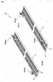
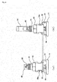
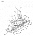
- Fig. 1 is a perspective view illustrating a configuration example of a seat moving/securing device in accordance with the first embodiment
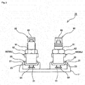
- Fig. 2 is a front view for describing the seat moving/securing device in accordance with the first embodiment
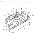
- Fig. 3 is a perspective view illustrating a configuration example of a main part of the seat moving/securing device for a front-side leg part in accordance with the first embodiment
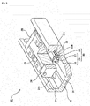
- Fig. 4 is a perspective view illustrating a configuration example of a main part of the seat moving/securing device for a rear-side leg part in accordance with the first embodiment.
- Fig. 1 is a perspective view illustrating a configuration example of a seat moving/securing device in accordance with the first embodiment
- Fig. 2 is a front view for describing the seat moving/securing device in accordance with the first embodiment
- Fig. 3 is a perspective view illustrating a configuration example of a main part of the seat moving/securing device for a front-side leg part in accordance with the
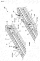
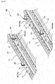
- FIG. 5 is a partially broken perspective view illustrating a linear guide in accordance with the first embodiment.
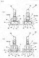
- Fig. 6 is a vertical cross-sectional view illustrating a state in which binding between a leg part attachment member for the front-side leg part and a flanged part is released in accordance with the first embodiment
- Fig. 7 is a vertical cross-sectional view illustrating a state in which the binding between the leg part attachment member for the front-side leg part and the flanged part is carried out in accordance with the first embodiment.
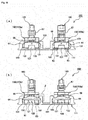
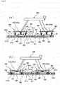
- Fig. 8 illustrates binding and release states between the leg part attachment member for the front-side leg part and the flanged part in accordance with the first embodiment.
- Fig. 8 illustrates binding and release states between the leg part attachment member for the front-side leg part and the flanged part in accordance with the first embodiment.
- FIG. 8(a) illustrates a state in which the binding state between the leg part attachment member for the front-side leg part and the flangedpart is released in accordance with the first embodiment
- Fig. 8(b) illustrates a state in which the binding state between the leg part attachment member for the front-side leg part and the flanged part is carried out in accordance with the first embodiment
- Fig. 9 is a vertical cross-sectional view illustrating a state in which binding between a leg part attachment member for the rear-side leg part and the flanged part is released in accordance with the first embodiment
- FIG. 10 is a vertical cross-sectional view illustrating a state in which the binding between the leg part attachment member for the rear-side leg part and the flanged part is carried out in accordance with the first embodiment.
- Fig. 11 illustrates binding and release states between the leg part attachment member for the rear-side leg part and the flanged part in accordance with the first embodiment.
- Fig. 11 (a) illustrates a state in which the binding state between the leg part attachment member for the rear-side leg part and the flanged part is released in accordance with the first embodiment
- Fig. 11 (b) illustrates a state in which the binding state between the leg part attachment member for the rear-side leg part and the flanged part is carried out in accordance with the first embodiment.
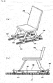
- Fig. 12 illustrates a seat using the seat moving/securing device in accordance with the first embodiment.
- Fig. 12(a) is a perspective view
- Fig. 12(b) is a side view illustrating a main part of the seat
- the seat moving/securing device 10 in accordance with the first embodiment is configured to include a long reference member 11 extending in a longitudinal direction of a seat installation surface and securely installed, a leg part attachment member 50 having securely installed therein a leg part of a seat 200, a linear guide 20 attached between the long reference member 11 and the leg part attachment member 50 and enabling the leg part attachment member 50 to move horizontally along a longitudinal direction of the long reference member 11, and a locking mechanism 60 securely installed on the leg part attachment member 50.
- the reference member 11 is a long member securely installed on the seat installation surface and a member serving as a reference of the seat moving/securing device 10 in accordance with the first embodiment.
- a cross-sectional shape of the reference member 11 is formed approximately in a U shape as illustrated in Fig. 2 , and with an opened part of the approximately U-shaped member facing upward, mechanisms for a front-side leg part (for example, a legpart attachment member 50a and the locking mechanism 60) of the seat 200 and mechanisms for a rear-side leg part (for example, a leg part attachment member 50b and the locking mechanism 60) of the seat 200, described below, are arranged in parallel in an internal space of the approximately U-shaped member.
- the leg part attachment member 50 is a member having securely installed therein the leg part of the seat 200 and, in the present embodiment, is configured to include the leg part attachment member 50a for the front-side leg part having securely installed therein a front leg of the seat 200 and the leg part attachment member 50b for the rear-side leg part having securely installed therein a rear leg of the seat 200.
- the below-mentioned locking mechanism 60 is securely installed on the leg part attachment member 50 (50a and 50b).
- the linear guide 20 enabling the leg part attachment member 50 (50a and 50b) to move horizontally along the longitudinal direction of the long reference member 11 is installed.
- the linear guide 20 in accordance with the present embodiment includes a track rail 21 serving as a track member and a moving block 23 serving as a moving member movably attached to the track rail 21 via a plurality of balls 22.
- the track rail 21 is a long member having an approximately U-shaped cross-section, is provided on inner side surfaces thereof with load rolling grooves 21a each on the right and left sides enabling the balls 22 to be received in the grooves and formed over the entire length of the track rail 21, and is a track member of a type of a so-called outer rail.
- the track rail 21 is provided with a plurality of bolt attachment holes 21b appropriately spaced in a longitudinal direction thereof.
- the track rail 21 is secured on an upper surface of the reference member 11 by means of bolts (not illustrated) screwed in the plurality of bolt attachment holes 21b.
- the moving block 23 is provided with two load rolling grooves 23a respectively opposed to the two load rolling grooves 21a each provided on the right and left sides of the track rail 21.
- the load rolling grooves 21a and 23a are combined to form two load rolling paths 25 between the track rail 21 and the moving block 23.
- the moving block 23 is also provided with two returning paths 26 extending to be parallel to the two load rolling paths 25.
- the moving block 23 further includes lid parts 28 on both end surfaces thereof, and not-illustrated ball guide grooves formed to cave in an arch-like manner in the lid part 28 cause direction change path 27 formed to project in an arch-like manner between the load rolling path 25 and the returning path 26 to be formed.
- the lid part 28 is reliably secured as a member serving as one end part of the moving block 23 to cause the direction change path 27 connecting the load rolling path 25 to the returning path 26 to be formed.
- the returning path 26 and the direction change paths 27 cause no-load rolling path 29 for the balls 22 to be formed, and the no-load rolling path 29 and the load rolling path 25 are combined to constitute endless circuit 30.
- the plurality of balls 22 are installed in the endless circuit 30 to circulate endlessly, and the moving block 23 can reciprocate relatively to the track rail 21.
- the track rail 21 included in the linear guide 20 is provided with a catch-formed part 31 extending in the longitudinal direction and having a dovetail-groove-shaped cross-section (refer to Figs. 2 , 5 , and the like).
- the catch-formed part 31 cooperates with the below-mentioned locking mechanism 60 to serve as a required component to exert a moving/securing function of the seat moving/securing device 10.
- the leg part attachment member 50a in accordance with the first embodiment is a member having a gate-like external shape and arranged to stride over the moving block 23 of the linear guide 20.
- the leg part attachment member 50a and the moving block 23 of the linear guide 20 are connected at approximately center parts of the leg part attachment member 50a and the moving block 23 via a bush 67 having a buffering function and made of a soft material.
- a coil spring 68 serving as an elastic body and arranged to surround the bush 67 is installed between the leg part attachment member 50a and the moving block 23 of the linear guide 20, a coil spring 68 serving as an elastic body and arranged to surround the bush 67 is installed.
- the coil spring 68 can exhibit a pressing force (elastic force).
- the leg part attachment member 50a moves in a direction toward the moving block 23 due to the effect of the downward pressing force against the effect of the elastic force of the coil spring 68, and a state in which the leg part attachment member 50a is pressed to the track rail 21 is maintained.
- the leg part attachment member 50a is provided with the locking mechanism 60.
- the locking mechanism 60 in accordance with the first embodiment is configured to include a rod housing 61 having a hollow hole and a rod member 63 serving as a shaft-like member provided to pass through the hollow hole included in the rod housing 61 and including on one end side thereof a flanged part 64 and including on the other end side thereof an operation lever part 65 formed in a cam shape.
- the rod housing 61 is adapted to support and guide the rod member 63 and is integrally provided with a screw 62 adapted to connect the rod housing 61 to the leg part attachment member 50a. Due to the screw 62, the rod housing 61 is securely installed to the leg part attachment member 50a to disable movement.
- the rod member 63 is a shaft-like member installed to pass through the hollow hole included in the rod housing 61 to enable up-and-down movement and includes the flanged part 64 on the lower end side.
- the operation lever part 65 formed in a cam shape is installed to enable tilt movement.
- the cam shape formed in the operation lever part 65 is configured to contact the upper end surface of the rod housing 61. Also, in the first embodiment, as illustrated in Figs.
- the cam shape takes effect so that the projecting amount of an upper end part of the rod member 63 proj ecting from the upper end surface of the rod housing 61 may decrease when the operation lever part 65 is turned down into a laid state
- the cam shape takes effect so that the projecting amount of the upper end part of the rod member 63 projecting from the upper end surface of the rod housing 61 may increase when the operation lever part 65 is turned up into an upright state.
- the projecting amount of the flanged part side of the rod member 63 projecting downward from the rod housing 61 increases, and the distance between the flanged part 64 and a bottom surface of the leg part attachment member 50a increases.
- the rod housing 61 is securely installed to the leg part attachment member 50a, and the flanged part 64 included in the rod member 63 is installed to be inserted in the catch-formed part 31 having the dovetail-groove-shaped cross-section.
- the cam shape included in the operation lever part 65 when the operation lever part 65 is turned down and tilted into the laid state, the projecting amount of the flanged part side of the rod member 63 projecting downward from the rod housing 61 increases, and the distance between the flanged part 64 and the bottom surface of the leg part attachment member 50a increases.
- the flanged part 64 moves inside the groove of the catch-formed part 31 in a direction toward a groove bottom, and the leg part attachment member 50a moves at an upper part of the groove of the catch-formed part 31 in a direction away from an entrance of the groove.
- Fig. 8 (a) in Fig. 8 which means a binding state between the leg part attachment member 50a and the flanged part 64 pressing the neighborhood of the catch-formed part 31 is released.
- the projecting amount of the flanged part side of the rod member 63 projecting downward from the rod housing 61 decreases, and the distance between the flanged part 64 and the bottom surface of the leg part attachment member 50a decreases. Accordingly, the flanged part 64 moves inside the groove of the catch-formed part 31 in a direction toward the entrance of the groove, and the leg part attachment member 50a moves in a direction approaching to the upper part of the entrance of the groove of the catch-formed part 31, that is, the neighborhood of a position in the track rail 21 provided with the catch-formed part 31.
- the flanged part 64 and the leg part attachment member 50a move in directions of interposing the entrance of the groove of the catch-formed part 31 therebetween from the inner part of the groove and the upper part of the groove and pressing each other.
- Fig. 8(b) in Fig. 8 Such a state is illustrated in Fig. 8(b) in Fig. 8 , which means the binding state between the leg part attachment member 50a and the flanged part 64 pressing the neighborhood of the catch-formed part 31 is carried out.
- an attachment position of the bush 67 serving as a connection part of the leg part attachment member 50a to the moving block 23 is located approximately at a center part of the leg part attachment member 50a, and an attachment position of the aforementioned locking mechanism 60 is located at a one-sided position of the gate-like shape out of the center of the leg part attachment member 50a. Accordingly, the pressing force of pressing the neighborhood of the catch-formed part 31 generated by the effect of the locking mechanism 60 for bringing about the binding state between the leg part attachment member 50a and the flanged part 64 are applied to the one-sided position of the gate-like shape of the leg part attachment member 50a.
- the bush 67 connecting the leg part attachment member 50a to the moving block 23 is a rigid body having no buffering function, worsening of an application balance of the pressing force may inhibit smooth binding/releasing operations.
- the bush 67 is made of a soft material having a buffering function. Since the bush 67 connecting the leg part attachment member 50a to the moving block 23 is made of a soft material having a buffering function to enable allowance to be provided between the leg part attachment member 50a and the moving block 23 in the binding state, securement and movement of the seat 200 by means of the seat moving/securing device 10 can be achieved suitably and easily.
- the leg part attachment member 50b in accordance with the first embodiment is a member having a gate-like external shape and arranged to stride over the moving block 23 of the linear guide 20.
- the leg part attachment member 50b and the moving block 23 of the linear guide 20 are connected at approximately center parts of the leg part attachment member 50b and the moving block 23 via the bush 67 having a buffering function and made of a soft material.
- the coil spring 68 serving as an elastic body and arranged to surround the bush 67 is installed between the leg part attachment member 50b and the moving block 23 of the linear guide 20, the coil spring 68 serving as an elastic body and arranged to surround the bush 67 is installed.
- the coil spring 68 can exhibit a pressing force (elastic force) .
- the leg part attachment member 50b moves in a direction toward the moving block 23 due to the effect of the downward pressing force against the effect of the elastic force of the coil spring 68, and a state in which the leg part attachment member 50b is pressed to the track rail 21 is maintained.
- the leg part attachment member 50b is provided with the locking mechanism 60.
- the locking mechanism 60 in accordance with the first embodiment is configured to include the rod housing 61 having a hollow hole and the rod member 63 serving as a shaft-like member provided to pass through the hollow hole included in the rod housing 61 and including on one end side thereof the flanged part 64 and including on the other end side thereof the operation lever part 65 formed in a cam shape.
- the rod housing 61 is adapted to support and guide the rod member 63 and is integrally provided with the screw 62 adapted to connect the rod housing 61 to the leg part attachment member 50b. Due to the screw 62, the rod housing 61 is securely installed to the leg part attachment member 50b to disable movement.
- the rod member 63 is a shaft-like member installed to pass through the hollow hole included in the rod housing 61 to enable up-and-down movement and includes the flanged part 64 on the lower end side.
- the operation lever part 65 formed in a cam shape is installed to enable tilt movement.
- the cam shape formed in the operation lever part 65 is configured to contact the upper end surface of the rod housing 61. Also, in the first embodiment, as illustrated in Figs.
- the rod housing 61 is securely installed to the leg part attachment member 50b, and the flanged part 64 included in the rod member 63 is installed to be inserted in the catch-formed part 31 having the dovetail-groove-shaped cross-section.
- the cam shape included in the operation lever part 65 when the operation lever part 65 is turned down and tilted into the laid state, the projecting amount of the flanged part side of the rod member 63 projecting downward from the rod housing 61 increases, and the distance between the flanged part 64 and the bottom surface of the leg part attachment member 50b increases.
- the flanged part 64 moves inside the groove of the catch-formed part 31 in a direction toward a groove bottom, and the leg part attachment member 50b moves at an upper part of the groove of the catch-formed part 31 in a direction away from an entrance of the groove.
- Fig. 11 (a) in Fig. 11 which means a binding state between the leg part attachment member 50b and the flanged part 64 pressing the neighborhood of the catch-formed part 31 is released.
- the projecting amount of the flanged part side of the rod member 63 projecting downward from the rod housing 61 decreases, and the distance between the flanged part 64 and the bottom surface of the leg part attachment member 50b decreases. Accordingly, the flanged part 64 moves inside the groove of the catch-formed part 31 in a direction toward the entrance of the groove, and the leg part attachment member 50b moves in a direction approaching to the upper part of the entrance of the groove of the catch-formed part 31, that is, the neighborhood of a position in the track rail 21 provided with the catch-formed part 31.
- the flanged part 64 and the leg part attachment member 50b move in directions of interposing the entrance of the groove of the catch-formed part 31 therebetween from the inner part of the groove and the upper part of the groove and pressing each other.
- Fig. 11(b) in Fig. 11 Such a state is illustrated in Fig. 11(b) in Fig. 11 , which means the binding state between the leg part attachment member 50b and the flanged part 64 pressing the neighborhood of the catch-formed part 31 is carried out.
- a pin-formed part 53 for positioning is formed on an opposed surface side of the leg part attachment member 50b to the track rail 21.
- a plurality of positioning holes 33 enabling the pin-formed part 53 included in the leg part attachment member 50b to be fitted therein are formed at predetermined intervals.
- the positioning holes 33 in accordance with the first embodiment are formed on a center bottom surface of the catch-formed part 31 having the dovetail-groove-shaped cross-section at regular intervals such as at one-inch pitches.
- positioning of the leg part attachment member 50b can be performed. That is, with use of the pin-formed part 53 and the positioning hole 33, positioning of the seat 200 attached to the leg part attachment member 50b can be performed accurately and easily.
- the leg part attachment member 50b connected to the seat 200 moves along the track rail 21 due to the effect of the linear guide 20.
- a position to allow the pin-formed part 53 and the positioning hole 33 to be fitted with each other that is, one of the one-inch-pitch positions for positioning the seat 200, can be searched.
- the locking mechanism 60 is made to function to cause the leg part attachment member 50b to exhibit a downward pressing force.
- the leg part attachment member 50b moves in a direction toward the track rail 21 (moving block 23), and the pin-formed part 53 and the positioning hole 33 are fitted and positioned. Also, the leg part attachment member 50b is pressed to the track rail 21, and the binding state between the leg part attachment member 50b and the flanged part 64 pressing the neighborhood of the catch-formed part 31 is carried out.
- an attachment position of the bush 67 serving as a connection part of the leg part attachment member 50b to the moving block 23 is located approximately at a center part of the leg part attachment member 50b, and an attachment position of the aforementioned locking mechanism 60 is located at a one-sided position of the gate-like shape out of the center of the leg part attachment member 50b. Accordingly, the pressing force of pressing the neighborhood of the catch-formed part 31 generated by the effect of the locking mechanism 60 for bringing about the binding state between the leg part attachment member 50b and the flanged part 64 are applied to the one-sided position of the gate-like shape of the leg part attachment member 50b.
- the bush 67 connecting the leg part attachment member 50b to the moving block 23 is a rigid body having no buffering function, worsening of an application balance of the pressing force may inhibit smooth binding/releasing operations.
- the bush 67 is made of a soft material having a buffering function. Since the bush 67 connecting the leg part attachment member 50b to the moving block 23 is made of a soft material having a buffering function to enable allowance to be provided between the leg part attachment member 50b and the moving block 23 in the binding state, securement and movement of the seat 200 by means of the seat moving/securing device 10 can be achieved suitably and easily.
- the pin-formed part 53 for positioning is formed only in the leg part attachment member 50b for the rear-side leg part of the seat 200 and is not formed in the leg part attachment member 50a for the front-side leg part of the seat 200.
- Such a configuration is employed in consideration of the fact that providing both the front and rear leg parts of the seat 200 with the positioning functions may make it difficult to perform stable and reliable positioning due to a formation error of the positioning hole 33, an error of the device, and the like.
- the fitting between the pin-formed part 53 and the positioning hole 33 for positioning of the seat 200 may be provided either on the front side or on the rear side.
- the pin-formed part 53 for positioning is formed only in the leg part attachment member 50b for the rear-side leg part of the seat 200 in the aforementioned first embodiment, the pin- formed part 53 maybe formed only in the leg part attachment member 50a for the front-side leg part of the seat 200.
- the leg part attachment members 50a and 50b can receive a downward force (that is, a force in a radial direction)
- the flanged part 64 can receive an upward force (that is, a force in an inverse radial direction)
- the pin-formed part 53 can exert functions of positioning and as a brake against a moving force in the front-and-rear direction (that is, a force in a sliding direction). Since the seat moving/securing device 10 in accordance with the first embodiment can exert such functions, when no person sits on the seat 200, and the binding state of the device is released, the linear guide 20 functions for smooth slide movement.
- the leg part attachment members 50a and 50b and the flanged part 64 can cooperate with each other to receive external load to be applied to the seat 200, namely, the forces in the radial and inverse radial directions. That is, in the first embodiment, size reduction of the linear guide 20 is achieved since the linear guide 20 does not need to receive the external load and has only to function for slide movement. This effect works especially in an aircraft field. In a case of the seat 200 of an aircraft, assumed is a situation in which the seat 200 under certain load is subject to high acceleration of several G. To design the device withstanding such a situation, the linear guide generally has to be enlarged. However, with the seat moving/securing device 10 in accordance with the first embodiment, since the linear guide 20 does not need to receive the external load, size reduction of the linear guide 20 can be achieved, which causes the device to be compact.
- the seat moving/securing device 10 in accordance with the first embodiment described above can be used, for example, by installing the seat 200 of an aircraft on the seat moving/securing device 10 as illustrated in Fig. 12 .
- the front leg of the seat 200 is secured to the leg part attachment hole 51 formed in the leg part attachment member 50a for the front-side leg part of the seat 200 by means of a known fastening means such as a bolt
- the rear leg of the seat 200 is secured to the leg part attachment hole 51 formed in the leg part attachment member 50b for the rear-side leg part of the seat 200 by means of a known fastening means such as a bolt, to complete attachment of the seat 200 to the seat moving/securing device 10.
- the operation lever part 65 is turned down and tilted into the laid state to cause the binding state to be released.
- the seat 200 can be moved.
- a position to allow the pin-formed part 53 and the positioning hole 33 to be fitted with each other that is, one of the one-inch-pitch positions for positioning the seat 200, can be searched.
- the operation lever part 65 is turned up and tilted into the upright state at the position to cause the seat 200 to be positioned and the binding state to be carried out.
- the seat 200 can be moved and secured easily and quickly. That is, in accordance with the first embodiment, it is possible to provide the seat moving/securing device 10 enabling the seat 200 to be moved and secured easily and quickly.
- Fig. 13 is a perspective view illustrating a configuration example of a seat moving/securing device in accordance with a second embodiment.
- Fig. 14 describes the seat moving/securing device in accordance with the second embodiment.
- Fig. 14(a) is a front view of the seat moving/securing device in accordance with the second embodiment
- Fig. 14(b) is a rear view of the seat moving/securing device in accordance with the second embodiment.
- Fig. 15 is a perspective view illustrating a state in which binding between a leg part attachment member and a flanged part of the seat moving/securing device is carried out in accordance with the second embodiment.
- Fig. 14 describes the seat moving/securing device in accordance with the second embodiment.
- Fig. 14(a) is a front view of the seat moving/securing device in accordance with the second embodiment
- Fig. 14(b) is a rear view of the seat moving/securing device in accordance with the second embodiment.
- Fig. 15
- FIG. 16 illustrates a state in which the binding between the leg part attachment member and the flanged part is carried out in accordance with the second embodiment.
- Fig. 16(a) is a front view illustrating a state in which the binding between the leg part attachment member and the flanged part is carried out in accordance with the second embodiment
- Fig. 16(b) is a rear view illustrating a state in which the binding between the leg part attachment member and the flanged part is carried out in accordance with the second embodiment.
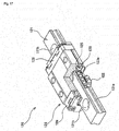
- Fig. 17 is a partially broken perspective view illustrating a linear guide in accordance with the second embodiment.
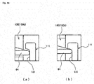
- Fig. 18 illustrates binding and release states between the leg part attachment member and the flanged part in accordance with the second embodiment.
- Fig. 16(a) is a front view illustrating a state in which the binding between the leg part attachment member and the flanged part is carried out in accordance with the second embodiment
- Fig. 16(b) is a rear view illustrating a state
- Fig. 18(a) is an enlarged view of a main part (a part labeled with reference numeral ⁇ in Fig. 14 (b) in Fig. 14 ) illustrating a state in which the binding state between the leg part attachment member and the flanged part is released in accordance with the second embodiment
- Fig. 18(b) is an enlarged view of amainpart (apart labeled with reference numeral ⁇ in Fig. 16(b) in Fig. 16 ) illustrating a state in which the binding state between the leg part attachment member and the flanged part is carried out in accordance with the second embodiment.
- Fig. 18(a) is an enlarged view of a main part (a part labeled with reference numeral ⁇ in Fig. 14 (b) in Fig. 14 ) illustrating a state in which the binding state between the leg part attachment member and the flanged part is released in accordance with the second embodiment
- Fig. 18(b) is an enlarged view of amainpart (
- FIG. 19 illustrates the binding state between the leg part attachment member for a front-side leg part and the flanged part in accordance with the second embodiment.
- Fig. 19(a) is a vertical cross-sectional view illustrating a state in which the binding state between the leg part attachment member for the front-side leg part and the flangedpart is released in accordance with the second embodiment
- Fig. 19(b) is a vertical cross-sectional view illustrating a state in which the binding state between the leg part attachment member for the front-side leg part and the flanged part is carried out in accordance with the second embodiment.
- Fig. 20 illustrates the binding state between the leg part attachment member for a rear-side leg part and the flanged part in accordance with the second embodiment.
- Fig. 20(a) is a vertical cross-sectional view illustrating a state in which the binding state between the leg part attachment member for the rear-side leg part and the flanged part is released in accordance with the second embodiment
- Fig. 20(b) is a vertical cross-sectional view illustrating a state in which the binding state between the leg part attachment member for the rear-side leg part and the flanged part is carried out in accordance with the second embodiment.
- the catch-formed part 31 extending in the longitudinal direction and having a dovetail-groove-shaped cross-section is formed in the track rail 21 included in the linear guide 20 .
- the catch-formed part having a dovetail-groove-shaped cross-section can be formed in a long reference member.
- a catch-formed part 131 in accordance with the second embodiment is illustrated in detail in Figs. 13 to 16 and the like.
- the seat moving/securing device 100 in accordance with the second embodiment is configured to include a long reference member 111 extending in a longitudinal direction of a seat installation surface and securely installed, a leg part attachment member 150 having securely installed therein a leg part of the seat 200, a linear guide 120 attached between the long reference member 111 and the leg part attachment member 150 and enabling the leg part attachment member 150 to move horizontally along a longitudinal direction of the long reference member 111, and a locking mechanism 160 securely installed on the leg part attachment member 150.
- the reference member 111 is a long member securely installed on the seat installation surface and a member serving as a reference of the seat moving/securing device 100 in accordance with the second embodiment.
- wall parts each formed approximately in an L shape for forming the catch-formed part 131 extending in the longitudinal direction and having a dovetail-groove-shaped cross-section are formed to erect as illustrated in Figs. 13 to 16 .
- a configuration of forming two catch-formed parts 131 in one reference member 111 is illustrated.
- One of the two catch-formed parts 131 is for a front-side leg part of the seat 200 while the other is for a rear-side leg part of the seat 200.
- the catch-formed part 131 cooperates with the below-mentioned locking mechanism 160 to serve as a required component to exert a moving/securing function of the seat moving/securing device 100.
- mechanisms for the front-side leg part (for example, a leg part attachment member 150a and the locking mechanism 160) of the seat 200 and mechanisms for the rear-side leg part (for example, a leg part attachment member 150b and the locking mechanism 160) of the seat 200, described below, are arranged, respectively.
- the leg part attachment member 150 is a member having securely installed therein the leg part of the seat 200 and, in the present embodiment, is configured to include the leg part attachment member 150a for the front-side leg part having securely installed therein a front leg of the seat 200 and the leg part attachment member 150b for the rear-side leg part having securely installed therein a rear leg of the seat 200.
- the below-mentioned locking mechanism 160 is securely installed on the leg part attachment member 150 (150a and 150b).
- the linear guide 120 enabling the leg part attachment member 150 (150a and 150b) to move horizontally along the longitudinal direction of the long reference member 111 is installed.
- the linear guide 120 in accordance with the present embodiment includes a track rail 121 serving as a track member and a moving block 123 serving as a moving member movably attached to the track rail 121 via a plurality of balls 122.
- the track rail 121 is a long member having an approximately rectangular cross-section and is provided on outer circumferential side surfaces thereof with load rolling grooves 121a each on the right and left sides enabling the balls 122 to be received in the grooves and formed over the entire length of the track rail 121.
- the track rail 121 is provided with a plurality of bolt attachment holes 121b appropriately spaced in a longitudinal direction thereof.
- the track rail 121 is secured in the catch-formed part 131 formed in the reference member 111 by means of bolts (not illustrated) screwed in the plurality of bolt attachment holes 121b.
- the moving block 123 is provided with two load rolling grooves 123a respectively opposed to the two load rolling grooves 121a each provided on the right and left sides of the track rail 121.
- the load rolling grooves 121a and 123a are combined to form two load rolling paths 125 between the track rail 121 and the moving block 123.
- the moving block 123 is also provided with two returning paths 126 extending to be parallel to the two load rolling paths 125.
- the moving block 123 further includes lid parts 128 on both end surfaces thereof, and not-illustrated ball guide groove formed to cave in an arch-like manner in the lid part 128 causes direction change path (not illustrated) formed to project in an arch-like manner between the load rolling path 125 and the returning path 126 to be formed.
- the lid part 128 is reliably secured as a member serving as one end part of the moving block 123 to cause the direction change path (not illustrated) connecting the load rolling path 125 to the returning path 126 to be formed.
- the returning path 126 and the direction change paths (not illustrated) cause no-load rolling paths for the balls 122 to be formed, and the no-load rolling path and the load rolling path 125 are combined to constitute endless circuit.
- the plurality of balls 122 are installed in the endless circuit to circulate endlessly, and the moving block 123 can reciprocate relatively to the track rail 121.
- Each of the leg part attachment members 150a and 150b in accordance with the second embodiment is a member having an approximately T external shape in a side view and arranged so that an umbrella part on one side of the approximately T shape may cover the moving block 123 of the linear guide 120.
- Each of the leg part attachment members 150a and 150b and the moving block 123 of the linear guide 120 are connected at an end part of each of the leg part attachment members 150a and 150b and an approximately center part of the moving block 123 via the bush 67 having a buffering function and made of a soft material.
- the coil spring 68 serving as an elastic body and arranged to surround the bush 67 is installed between each of the leg part attachment members 150a and 150b and the moving block 123 of the linear guide 120.
- the coil spring 68 can exhibit a pressing force (elastic force) . Accordingly, in a normal case in which each of the leg part attachment members 150a and 150b is not subject to an external force, forces are applied in directions in which each of the leg part attachment members 150a and 150b and the moving block 123 separate from each other due to the effect of the elastic force of the coil spring 68, and a state in which each of the leg part attachment members 150a and 150b is lifted upward with respect to the moving block 123 is thus maintained.
- a pressing force elastic force
- each of the leg part attachment members 150a and 150b moves in a direction toward the moving block 123 due to the effect of the downward pressing force against the effect of the elastic force of the coil spring 68, and a state in which each of the leg part attachment members 150a and 150b is pressed to the reference member 111 is maintained.
- each of the leg part attachment members 150a and 150b is provided with the locking mechanism 160.
- the locking mechanism 160 in accordance with the second embodiment is configured to include the rod housing 61 having a hollow hole and the rod member 63 serving as a shaft-like member provided to pass through the hollow hole included in the rod housing 61 and including on one end side thereof the flanged part 64 and including on the other end side thereof the operation lever part 65 formed in a cam shape.
- the locking mechanism 160 in accordance with the second embodiment has a substantially similar structure to that of the aforementioned locking mechanism 60 in accordance with the first embodiment, detailed description of the locking mechanism 160 will be omitted.
- the locking mechanism 160 in accordance with the second embodiment differs from the locking mechanism 60 in accordance with the first embodiment in that the cam shape formed in the operation lever part 65 is different. That is, as illustrated in Figs. 19 , 20 , and the like, in a case of the second embodiment, binding is released when the operation lever part 65 is turned up and tilted into an upright state, and the binding is carried out when the operation lever part 65 is turned down and tilted into a laid state.
- the flanged part 64 included in the rod member 63 is inserted and installed in the catch-formed part 131 having the dovetail-groove-shaped cross-section, and a front view (rear view) of each of the leg part attachment members 150a and 150b having an approximately T external shape in a side view is an approximately n shape and a gate-like shape having long legs.
- a front view (rear view) of each of the leg part attachment members 150a and 150b having an approximately T external shape in a side view is an approximately n shape and a gate-like shape having long legs.
- Each of the leg part attachment members 150a and 150b and the flanged part 64 pressing the inner wall surface of the catch-formed part 131 respectively move away from the inner wall surface of the catch-formed part 131 inward to cause the binding state to be released (refer to Fig. 18 (a) in Fig. 18 as well) .
- the leg part attachment member 150b in accordance with the second embodiment for the rear-side leg part having securely installed therein the rear leg of the seat 200 is provided with the pin-formed part 53 for positioning.
- the pin-formed part 53 is formed on an opposed surface side of the leg part attachment member 150b to the reference member 111.
- a plurality of positioning holes 133 enabling the pin-formed part 53 included in the leg part attachment member 150b to be fitted therein are formed at predetermined intervals to keep away from the installation position of the track rail 121 included in the linear guide 120 .
- the positioning holes 133 in accordance with the second embodiment are formed on the bottom surface of the catch-formed part 131 having the dovetail-groove-shaped cross-section at regular intervals such as at one-inch pitches.
- each of the leg part attachment members 150a and 150b connected to the seat 200 moves along the track rail 121 due to the effect of the linear guide 120.
- a position to allow the pin-formed part 53 and the positioning hole 133 to be fitted with each other that is, one of the one-inch-pitch positions for positioning the seat 200, can be searched.
- the locking mechanism 160 is made to function to cause each of the leg part attachment members 150a and 150b to exhibit a downward pressing force.
- the leg part attachment member 150b moves in a direction toward the reference member 111 (moving block 123), and the pin-formed part 53 and the positioning hole 133 are fitted and positioned. Also, each of the leg part attachment members 150a and 150b is pressed to the reference member 111, and the binding state between each of the leg part attachment members 150a and 150b and the flanged part 64 pressing the inner wall surface of the catch-formed part 131 outward is carried out.
- the pin-formed part 53 for positioning is formed only in the leg part attachment member 150b for the rear-side leg part of the seat 200 and is not formed in the leg part attachment member 150a for the front-side leg part of the seat 200 (refer to Fig. 19 ).
- Such a configuration is employed in consideration of the fact that providing both the front and rear leg parts of the seat 200 with the positioning functions may make it difficult to perform stable and reliable positioning due to a formation error of the positioning hole 133, an error of the device, and the like.
- the fitting between the pin-formed part 53 and the positioning hole 133 for positioning of the seat 200 may be provided either on the front side or on the rear side.
- the pin-formed part 53 for positioning is formed only in the leg part attachment member 150b for the rear-side leg part of the seat 200 in the aforementioned second embodiment, the pin-formed part 53 maybe formed only in the leg part attachment member 150a for the front-side leg part of the seat 200.
- Configurations and effects of the second embodiment other than those described above are basically similar to those of the first embodiment. Accordingly, in the seat moving/securing device 100 in accordance with the second embodiment, stable moving/securing operations can be achieved, and long duration of the device is also achieved.
- the seat moving/securing device 100 in accordance with the second embodiment described above can be used by installing the seat 200 of an aircraft on the seat moving/securing device 100 as illustrated in Fig. 12 .
- the seat moving/securing device 100 it is possible to provide the seat moving/securing device 100 enabling the seat 200 to be moved and secured easily and quickly.
- Each of the aforementioned first and second embodiments includes the catch-formed part 31 having a dovetail-groove-shaped cross-section and each of the locking mechanisms 60 and 160 each including the rod housing 61 having a hollow hole and the rod member 63 serving as a shaft-like member provided to pass through the hollow hole included in the rod housing 61 and including on one end side thereof the flanged part 64 and including on the other end side thereof the operation lever part 65 formed in a cam shape.
- Fig. 21 is a perspective view illustrating a configuration example of a seat moving/securing device in accordance with a third embodiment.
- Fig. 22 describes the seat moving/securing device in accordance with the third embodiment.
- Fig. 22(a) illustrates a state in which binding of a seat is released
- Fig. 22 (b) illustrates a state in which the binding of the seat is carried out.
- a seat moving/securing device 300 in accordance with the third embodiment described below similar or identical components to those in the first and second embodiments are shown with the same reference numerals, and description of the duplicate components may be omitted.
- the seat moving/securing device 300 in accordance with the third embodiment is configured to include a long reference member 311 extending in a longitudinal direction of a seat installation surface and securely installed, a leg part attachment member 350 having securely installed therein a leg part of the seat 200, a linear guide 320 attached between the long reference member 311 and the leg part attachment member 350 and enabling the leg part attachment member 350 to move horizontally along a longitudinal direction of the long reference member 311, and a locking mechanism 360 securely installed on the leg part attachment member 350.
- the reference member 311 is a long member securely installed on the seat installation surface and a member serving as a reference of the seat moving/securing device 300 in accordance with the third embodiment. As illustrated in Fig. 22 , the reference member 311 is provided with a plurality of attachment holes 311a and 311b at predetermined intervals in the longitudinal direction. In Fig. 22 , the attachment holes 311a are screw holes for use in connection and securement to a track rail 321 included in the linear guide 320, and the attachment holes 311b are screw holes for use in connection and securement to attachment/securement bolts 361 included in the locking mechanism 360.
- the leg part attachment member 350 is a member having securely installed therein the leg part of the seat 200, and, in the present embodiment, the leg part attachment member 350a for the front-side leg part having securely installed therein the front leg of the seat 200 and the leg part attachment member 350b for the rear-side leg part having securely installed therein the rear leg of the seat 200 have equal configurations.
- the leg part attachment member 350 (350a and 350b) in accordance with the third embodiment has a gate-like external shape and includes a pair of locking mechanisms 360 on both sides in the front-and-rear direction of the slide movement direction, which is the longitudinal direction of the reference member 311 and the track rail 321.
- the linear guide 320 enabling the leg part attachment member 350 (350a and 350b) to move horizontally along the longitudinal direction of the long reference member 311 is installed.
- the linear guide 320 in accordance with the present embodiment is of a similar type to the linear guide 120 illustrated in Fig. 17 and includes the track rail 321 serving as a track member and a moving block 323 serving as a moving member movably attached to the track rail 321 via the plurality of balls 122.
- the track rail 321 is a long member having an approximately rectangular cross-section and is provided on outer circumferential side surfaces thereof with the load rolling grooves 121a each on the right and left sides enabling the balls 122 to be received in the grooves and formed over the entire length of the track rail 321.
- the track rail 321 is provided with a plurality of bolt attachment holes 321a and opening holes 321b appropriately spaced in the longitudinal direction thereof.
- the track rail 321 is secured to the reference member 311 by inserting bolts 400 into the plurality of bolt attachment holes 321a and screwing the bolts 400 into the attachment holes 311a formed in the reference member 311.
- the opening hole 321b formed in the track rail 321 is a hole adapted to have the attachment/securement bolt 361 included in the locking mechanism 360 inserted therein.
- a secured state between the reference member 311 and the leg part attachment member 350 (350a and 350b) is achieved by inserting the attachment/securement bolt 361 included in the locking mechanism 360 into the opening hole 321b formed in the track rail 321 and screwing the attachment/securement bolt 361 into the attachment hole 311b formed in the reference member 311.
- the leg part attachment member 350 (350a and 350b) in accordance with the third embodiment is provided approximately at a center position of the gate-like shape with a coil spring 368 serving as an elastic body, and the coil spring 368 connects the leg part attachment member 350 (350a and 350b) to the moving block 323.
- the coil spring 368 can exhibit a pressing force (elastic force) . Accordingly, as illustrated in Fig. 22 (a) in Fig.
- the locking mechanism 360 functions, that is, in a state in which a downward pressing force against the effect of the elastic force of the coil spring 368 is applied to the side of the seat 200, by inserting the attachment/securement bolt 361 included in the locking mechanism 360 into the opening hole 321b formed in the track rail 321 and screwing the attachment/securement bolt 361 into the attachment hole 311b formed in the reference member 311, the secured state between the reference member 311 and the leg part attachment member 350 (350a and 350b) can be achieved. That is, a state in which the binding of the leg part attachment member 350 (350a and 350b) is carried out as illustrated in Fig. 22(b) in Fig. 22 can be achieved.
- this binding state is carried out by screwing connection between the attachment/securement bolt 361 and the attachment hole 311b, this binding state can suitably receive any external force to be applied to the seat 200.
- the gate-like leg part attachment member 350 (350a and 350b) is in a state of pressing the gate-like leg part to the upper surface of the track rail 321. Such a state thus contributes to achievement of the stable secured state between the reference member 311 and the leg part attachment member 350 (350a and 350b).
- the seat moving/securing device 300 in accordance with the third embodiment has been described above as one of various embodiments to which the present invention can be applied.
- the seat 200 can be moved and secured easily and quickly in a similar manner to that in the case of the first or second embodiment.
- the number of leg parts of the seat 200 may be any number, and the configuration of the seat moving/securing device 10 or 100 may be changed in accordance with the number of leg parts. That is, the number of leg part attachment members 150a for the front-side leg part and leg part attachment members 150b for the rear-side leg part of the seat 200 can arbitrarily be changed.
- leg part attachment member 150a for the front-side leg part and the leg part attachment member 150b for the rear-side leg part of the seat 200
- the scope of the present invention is not limited to the configuration of the parallel arrangement, and a configuration of arranging in series the leg part attachment member 150a for the front-side leg part and the leg part attachment member 150b for the rear-side leg part of the seat 200 can be employed.
- the shape of the leg part attachment member 150 (150a and 150b), the attachment position of the locking mechanism 60 or 160 to the leg part attachment member 150 (150a and 150b), the formation position and shape of the pin-formed part 53, and the like can arbitrarily be changed within the scope of enabling a similar effect to that of each of the above embodiments to be exerted.
- each of the above embodiments has illustrated that, by arbitrarily changing the cam shape formed in the operation lever part 65, the binding carrying-out state and the binding releasing state are switchable as a resulting state caused by turning down and tilting the operation lever part 65 into the laid state and a resulting state caused by turning up and tilting the operation lever part 65 into the upright state. That is, whether the binding state is established when the operation lever part 65 is turned down or when the operation lever part 65 is turned up can arbitrarily be selected in accordance with conditions and the like of a place to install the seat moving/securing device according to the present invention.
- rod housing 61 and the leg part attachment member 50 or 150 are configured as separate members.
- the rod housing 61 and the leg part attachment member 50 or 150 can be configured as an integral member.
- the leg part attachment member 150 (150a or 150b) or 350 (350a or 350b) is installed individually to each of the leg parts provided at the front and rear portions of the seat 200.
- the leg part attachment member according to the present invention can be formed to connect the plurality of leg parts of the seat 200 to each other.
- Fig. 23 illustrates a modification example of the seat moving/securing device in accordance with the third embodiment.
- Fig. 23 (a) is an external perspective view of the device
- Fig. 23 (b) is a side view of the device.
- Fig. 23 (a) is an external perspective view of the device
- Fig. 23 (b) is a side view of the device.
- leg part attachment member 450 formed to extend in the longitudinal direction to connect the front and rear leg parts of the seat 200 to each other, the leg part attachment member 450 can press the track rail 321 over a broader range of the upper surface of the track rail 321. Accordingly, by employing the configuration illustrated in Fig. 23 , a more secured state between the reference member 311 and the leg part attachment member 450 can be achieved.
- the seat moving/securing device 10, 100, or 300 in accordance with each of the above embodiments is used by installing the seat 200 of an aircraft on the seat moving/securing device 10, 100, or 300 as illustrated in Fig. 12 or the like has been illustrated.
- the application range of the seat moving/securing device according to the present invention is not limited to the field of the aircraft.
- the seat moving/securing device according to the present invention can be applied to any places, means, buildings, and the like enabling an effect to be obtained by moving and securing the seat 200 easily and quickly such as transportation means, such as a motor-coach, other than the aircraft, and accommodation facilities, such as a theater, a movie theater, and a gymnasium.
- the track rail 321 and the reference member 311 are provided with the multiple bolt attachment holes 321a, opening holes 321b, and attachment holes 311a and 311b.
- these holes may be provided in accordance with the securement intervals of the seat moving/securing device, and the intervals and number of the holes are not required to be those illustrated in the figures.
- the installation intervals and the installation number of the bolt attachment holes 321a, opening holes 321b, and attachment holes 311a and 311b can arbitrarily be changed.
Landscapes
- Engineering & Computer Science (AREA)
- Aviation & Aerospace Engineering (AREA)
- Transportation (AREA)
- Mechanical Engineering (AREA)
- Seats For Vehicles (AREA)
Abstract
Description
- The present invention relates to a seat moving/securing device.
- In general, in a transportation means such as an aircraft and a motor-coach, seats seated by passengers are secured in advance. For this reason, an operating company operating the transportation means has a business limitation in which the operating company must sell boarding tickets and passenger tickets to customers to correspond to the predetermined number of seats.
- However, in the transportation means such as an aircraft and a motor-coach, in a case in which the distance between seats in a front-and-rear direction can be changed in accordance with a load factor, more diversified services can be offered. For example, in a case in which the load factor is high, the distance between seats in the front-and-rear direction is shortened so that more passengers may use the transportation means to enable the number of passengers accommodated by one aircraft or one motor-coach to be increased. Consequently, in a peak season in which a transportation demand increases, passengers who would move on to other transportation means in a usual case can be acquired. Also, for example, in a case in which the load factor is low, the distance between seats in the front-and-rear direction is increased to enable seats improved in comfort to be prepared. Thus, even in an off-season in which the transportation demand decreases, a unit price per passenger can be raised by improving the value of the seat. In this manner, in the conventional transportation means, desired is a seat moving/securing device enabling an optimal service to be offered in accordance with various circumstances by shortening the distance between seats seated by passengers in the front-and-rear direction or increasing the distance between seats in the front-and-rear direction.
- As literature disclosing the contents relating to the technique of this kind, Patent Literature 1 described below exists, for example. In Patent Literature 1 described below, a method for moving a seat to be used to move a seat in an aircraft is disclosed.
- Patent Literature 1:
JP 2006-27352 A - However, the method for moving a seat described in Patent Literature 1 described above requires many members such as a jack device and an adapter member and many processes for moving a seat when the seat is moved, which requires great effort to move the seat.
- That is, while Patent Literature 1 described above discloses an idea itself of moving a seat in an aircraft, Patent Literature 1 does not disclose a means to move or secure the seat easily and quickly. Accordingly, the method disclosed in Patent Literature 1 described above is nothing less than a technique not actually applicable to a transportation means, which is generally operated by minute.
- The present invention is accomplished by taking the cases presenting in the above conventional techniques into consideration thereof, and an object thereof is to provide a seat moving/securing device enabling a seat for use in a transportation means such as an aircraft and a motor-coach to be moved and secured easily and quickly.
- A seat moving/securing device according to the present invention includes: a long reference member extending in a longitudinal direction of a seat installation surface and securely installed; a leg part attachment member having securely installed therein a leg part of a seat; a linear guide attached between the long reference member and the leg part attachment member and enabling the leg part attachment member to move horizontally along a longitudinal direction of the long reference member; and a locking mechanism securely installed on the leg part attachment member, in which an elastic body exhibiting a pressing force is installed between the leg part attachment member and the linear guide.
- According to the present invention, it is possible to provide a seat moving/securing device enabling a seat to be moved and secured easily and quickly.
-
-
Fig. 1 is a perspective view illustrating a configuration example of a seat moving/securing device in accordance with a first embodiment. -
Fig. 2 is a front view for describing the seat moving/securing device in accordance with the first embodiment. -
Fig. 3 is a perspective view illustrating a configuration example of a main part of the seat moving/securing device for a front-side leg part in accordance with the first embodiment. -
Fig. 4 is a perspective view illustrating a configuration example of a main part of the seat moving/securing device for a rear-side leg part in accordance with the first embodiment. -
Fig. 5 is a partially broken perspective view illustrating a linear guide in accordance with the first embodiment. -
Fig. 6 is a vertical cross-sectional view illustrating a state in which binding between a leg part attachment member for the front-side leg part and a flanged part is released in accordance with the first embodiment. -
Fig. 7 is a vertical cross-sectional view illustrating a state in which the binding between the leg part attachment member for the front-side leg part and the flanged part is carried out in accordance with the first embodiment. -
Fig. 8 illustrates binding and release states between the leg part attachment member for the front-side leg part and the flanged part in accordance with the first embodiment,Fig. 8 (a) inFig. 8 illustrates a state in which the binding state between the leg part attachment member for the front-side leg part and the flanged part is released in accordance with the first embodiment, andFig. 8 (b) inFig. 8 illustrates a state in which the binding state between the leg part attachment member for the front-side leg part and the flanged part is carried out in accordance with the first embodiment. -
Fig. 9 is a vertical cross-sectional view illustrating a state in which binding between a leg part attachment member for the rear-side leg part and the flanged part is released in accordance with the first embodiment. -
Fig. 10 is a vertical cross-sectional view illustrating a state in which the binding between the leg part attachment member for the rear-side leg part and the flanged part is carried out in accordance with the first embodiment. -
Fig. 11 illustrates binding and release states between the leg part attachment member for the rear-side leg part and the flanged part in accordance with the first embodiment,Fig. 11 (a) inFig. 11 illustrates a state in which the binding state between the leg part attachment member for the rear-side leg part and the flanged part is released in accordance with the first embodiment, andFig. 11(b) inFig. 11 illustrates a state in which the binding state between the leg part attachment member for the rear-side leg part and the flanged part is carried out in accordance with the first embodiment. -
Fig. 12 illustrates a seat using the seat moving/securing device in accordance with the first embodiment,Fig. 12(a) inFig. 12 is a perspective view, andFig. 12 (b) inFig. 12 is a side view illustrating a main part of the seat. -
Fig. 13 is a perspective view illustrating a configuration example of a seat moving/securing device in accordance with a second embodiment -
Fig. 14 describes the seat moving/securing device in accordance with the second embodiment,Fig. 14(a) inFig. 14 is a front view of the seat moving/securing device in accordance with the second embodiment, andFig. 14(b) inFig. 14 is a rear view of the seat moving/securing device in accordance with the second embodiment. -
Fig. 15 is a perspective view illustrating a state in which binding between a leg part attachment member and a flanged part of the seat moving/securing device is carried out in accordance with the second embodiment. -
Fig. 16 illustrates a state in which the binding between the leg part attachment member and the flanged part is carried out in accordance with the second embodiment,Fig. 16(a) inFig. 16 is a front view illustrating a state in which the binding between the leg part attachment member and the flanged part is carried out in accordance with the second embodiment, andFig. 16(b) inFig. 16 is a rear view illustrating a state in which the binding between the leg part attachment member and the flanged part is carried out in accordance with the second embodiment. -
Fig. 17 is a partially broken perspective view illustrating a linear guide in accordance with the second embodiment. -
Fig. 18 illustrates binding and release states between the leg part attachment member and the flanged part in accordance with the second embodiment,Fig. 18 (a) inFig. 18 is an enlarged view of a main part (a part labeled with reference numeral α inFig. 15(b) inFig. 15 ) illustrating a state in which the binding state between the leg part attachment member and the flanged part is released in accordance with the second embodiment, andFig. 18 (b) inFig. 18 is an enlarged view of a main part (a part labeled with reference numeral β inFig. 17(b) inFig. 17 ) illustrating a state in which the binding state between the leg part attachment member and the flanged part is carried out in accordance with the second embodiment. -
Fig. 19 illustrates the binding state between the leg part attachment member for a front-side leg part and the flanged part in accordance with the second embodiment,Fig. 19(a) inFig. 19 is a vertical cross-sectional view illustrating a state in which the binding state between the leg part attachment member for the front-side leg part and the flanged part is released in accordance with the second embodiment, andFig. 19 (b) inFig. 19 is a vertical cross-sectional view illustrating a state in which the binding state between the leg part attachment member for the front-side leg part and the flanged part is carried out in accordance with the second embodiment. -
Fig. 20 illustrates the binding state between the leg part attachment member for a rear-side leg part and the flanged part in accordance with the second embodiment,Fig. 20(a) inFig. 20 is a vertical cross-sectional view illustrating a state in which the binding state between the leg part attachment member for the rear-side leg part and the flanged part is released in accordance with the second embodiment, andFig. 20(b) inFig. 20 is a vertical cross-sectional view illustrating a state in which the binding state between the leg part attachment member for the rear-side leg part and the flanged part is carried out in accordance with the second embodiment -
Fig. 21 is a perspective view illustrating a configuration example of a seat moving/securing device in accordance with a third embodiment. -
Fig. 22 describes the seat moving/securing device in accordance with the third embodiment,Fig. 22(a) inFig. 22 illustrates a state in which binding of a seat is released, andFig. 22 (b) inFig. 22 illustrates a state in which the binding of the seat is carried out. -
Fig. 23 illustrates a modification example of the seat moving/securing device in accordance with the third embodiment,Fig. 23(a) inFig. 23 is an external perspective view of the device, andFig. 23 (b) inFig. 23 is a side view of the device. - Hereinbelow, embodiments for carrying out the present invention will be described with reference to the drawings. It is to be noted that each of below embodiments does not limit the invention according to each claim, and that all combined characteristics described in each of the embodiments are not necessarily required as means to achieve the invention.
- First, a configuration example of a seat moving/securing
device 10 in accordance with a first embodiment will be described with reference toFigs. 1 to 12 .Fig. 1 is a perspective view illustrating a configuration example of a seat moving/securing device in accordance with the first embodiment, andFig. 2 is a front view for describing the seat moving/securing device in accordance with the first embodiment.Fig. 3 is a perspective view illustrating a configuration example of a main part of the seat moving/securing device for a front-side leg part in accordance with the first embodiment, andFig. 4 is a perspective view illustrating a configuration example of a main part of the seat moving/securing device for a rear-side leg part in accordance with the first embodiment.Fig. 5 is a partially broken perspective view illustrating a linear guide in accordance with the first embodiment.Fig. 6 is a vertical cross-sectional view illustrating a state in which binding between a leg part attachment member for the front-side leg part and a flanged part is released in accordance with the first embodiment, andFig. 7 is a vertical cross-sectional view illustrating a state in which the binding between the leg part attachment member for the front-side leg part and the flanged part is carried out in accordance with the first embodiment.Fig. 8 illustrates binding and release states between the leg part attachment member for the front-side leg part and the flanged part in accordance with the first embodiment. InFig. 8, Fig. 8(a) illustrates a state in which the binding state between the leg part attachment member for the front-side leg part and the flangedpart is released in accordance with the first embodiment, andFig. 8(b) illustrates a state in which the binding state between the leg part attachment member for the front-side leg part and the flanged part is carried out in accordance with the first embodiment.Fig. 9 is a vertical cross-sectional view illustrating a state in which binding between a leg part attachment member for the rear-side leg part and the flanged part is released in accordance with the first embodiment, andFig. 10 is a vertical cross-sectional view illustrating a state in which the binding between the leg part attachment member for the rear-side leg part and the flanged part is carried out in accordance with the first embodiment.Fig. 11 illustrates binding and release states between the leg part attachment member for the rear-side leg part and the flanged part in accordance with the first embodiment. InFig. 11, Fig. 11 (a) illustrates a state in which the binding state between the leg part attachment member for the rear-side leg part and the flanged part is released in accordance with the first embodiment, andFig. 11 (b) illustrates a state in which the binding state between the leg part attachment member for the rear-side leg part and the flanged part is carried out in accordance with the first embodiment.Fig. 12 illustrates a seat using the seat moving/securing device in accordance with the first embodiment. InFig. 12, Fig. 12(a) is a perspective view, andFig. 12(b) is a side view illustrating a main part of the seat. - As illustrated in detail in
Figs. 1 and2 , the seat moving/securingdevice 10 in accordance with the first embodiment is configured to include along reference member 11 extending in a longitudinal direction of a seat installation surface and securely installed, a legpart attachment member 50 having securely installed therein a leg part of aseat 200, alinear guide 20 attached between thelong reference member 11 and the legpart attachment member 50 and enabling the legpart attachment member 50 to move horizontally along a longitudinal direction of thelong reference member 11, and alocking mechanism 60 securely installed on the legpart attachment member 50. - The
reference member 11 is a long member securely installed on the seat installation surface and a member serving as a reference of the seat moving/securingdevice 10 in accordance with the first embodiment. A cross-sectional shape of thereference member 11 is formed approximately in a U shape as illustrated inFig. 2 , and with an opened part of the approximately U-shaped member facing upward, mechanisms for a front-side leg part (for example, alegpart attachment member 50a and the locking mechanism 60) of theseat 200 and mechanisms for a rear-side leg part (for example, a legpart attachment member 50b and the locking mechanism 60) of theseat 200, described below, are arranged in parallel in an internal space of the approximately U-shaped member. - The leg
part attachment member 50 is a member having securely installed therein the leg part of theseat 200 and, in the present embodiment, is configured to include the legpart attachment member 50a for the front-side leg part having securely installed therein a front leg of theseat 200 and the legpart attachment member 50b for the rear-side leg part having securely installed therein a rear leg of theseat 200. On the leg part attachment member 50 (50a and 50b), the below-mentionedlocking mechanism 60 is securely installed. - Between the
reference member 11 and the leg part attachment member 50 (50a and 50b), thelinear guide 20 enabling the leg part attachment member 50 (50a and 50b) to move horizontally along the longitudinal direction of thelong reference member 11 is installed. As illustrated inFig. 5 , thelinear guide 20 in accordance with the present embodiment includes atrack rail 21 serving as a track member and a movingblock 23 serving as a moving member movably attached to thetrack rail 21 via a plurality ofballs 22. - The
track rail 21 is a long member having an approximately U-shaped cross-section, is provided on inner side surfaces thereof withload rolling grooves 21a each on the right and left sides enabling theballs 22 to be received in the grooves and formed over the entire length of thetrack rail 21, and is a track member of a type of a so-called outer rail. Thetrack rail 21 is provided with a plurality of bolt attachment holes 21b appropriately spaced in a longitudinal direction thereof. Thetrack rail 21 is secured on an upper surface of thereference member 11 by means of bolts (not illustrated) screwed in the plurality of bolt attachment holes 21b. - The moving
block 23 is provided with twoload rolling grooves 23a respectively opposed to the twoload rolling grooves 21a each provided on the right and left sides of thetrack rail 21. Theload rolling grooves load rolling paths 25 between thetrack rail 21 and the movingblock 23. The movingblock 23 is also provided with two returningpaths 26 extending to be parallel to the twoload rolling paths 25. The movingblock 23 further includeslid parts 28 on both end surfaces thereof, and not-illustrated ball guide grooves formed to cave in an arch-like manner in thelid part 28 cause direction changepath 27 formed to project in an arch-like manner between theload rolling path 25 and the returningpath 26 to be formed. Thelid part 28 is reliably secured as a member serving as one end part of the movingblock 23 to cause the direction changepath 27 connecting theload rolling path 25 to the returningpath 26 to be formed. The returningpath 26 and thedirection change paths 27 cause no-load rolling path 29 for theballs 22 to be formed, and the no-load rolling path 29 and theload rolling path 25 are combined to constituteendless circuit 30. With such a configuration, the plurality ofballs 22 are installed in theendless circuit 30 to circulate endlessly, and the movingblock 23 can reciprocate relatively to thetrack rail 21. - In the seat moving/securing
device 10 in accordance with the first embodiment, thetrack rail 21 included in thelinear guide 20 is provided with a catch-formedpart 31 extending in the longitudinal direction and having a dovetail-groove-shaped cross-section (refer toFigs. 2 ,5 , and the like). The catch-formedpart 31 cooperates with the below-mentionedlocking mechanism 60 to serve as a required component to exert a moving/securing function of the seat moving/securingdevice 10. - Next, referring to
Figs. 2 ,3 ,6 to 8 , configurations of the legpart attachment member 50a and thelocking mechanism 60 serving as mechanisms for the front-side leg part of theseat 200 will be described. - The leg
part attachment member 50a in accordance with the first embodiment is a member having a gate-like external shape and arranged to stride over the movingblock 23 of thelinear guide 20. The legpart attachment member 50a and the movingblock 23 of thelinear guide 20 are connected at approximately center parts of the legpart attachment member 50a and the movingblock 23 via abush 67 having a buffering function and made of a soft material. Also, between the legpart attachment member 50a and the movingblock 23 of thelinear guide 20, acoil spring 68 serving as an elastic body and arranged to surround thebush 67 is installed. Thecoil spring 68 can exhibit a pressing force (elastic force). Accordingly, in a normal case in which the legpart attachment member 50a is not subject to an external force, a force is applied in directions in which the legpart attachment member 50a and the movingblock 23 separate from each other due to the effect of the elastic force of thecoil spring 68, and a state in which the legpart attachment member 50a is lifted upward with respect to the movingblock 23 is thus maintained. Conversely, in a case in which the below-mentionedlocking mechanism 60 acts to cause a downward pressing force to be applied to the legpart attachment member 50a, the legpart attachment member 50a moves in a direction toward the movingblock 23 due to the effect of the downward pressing force against the effect of the elastic force of thecoil spring 68, and a state in which the legpart attachment member 50a is pressed to thetrack rail 21 is maintained. - Also, the leg
part attachment member 50a is provided with thelocking mechanism 60. Thelocking mechanism 60 in accordance with the first embodiment is configured to include arod housing 61 having a hollow hole and arod member 63 serving as a shaft-like member provided to pass through the hollow hole included in therod housing 61 and including on one end side thereof aflanged part 64 and including on the other end side thereof anoperation lever part 65 formed in a cam shape. - The
rod housing 61 is adapted to support and guide therod member 63 and is integrally provided with ascrew 62 adapted to connect therod housing 61 to the legpart attachment member 50a. Due to thescrew 62, therod housing 61 is securely installed to the legpart attachment member 50a to disable movement. - The
rod member 63 is a shaft-like member installed to pass through the hollow hole included in therod housing 61 to enable up-and-down movement and includes theflanged part 64 on the lower end side. On the other hand, on the upper end side, theoperation lever part 65 formed in a cam shape is installed to enable tilt movement. Here, the cam shape formed in theoperation lever part 65 is configured to contact the upper end surface of therod housing 61. Also, in the first embodiment, as illustrated inFigs. 6 to 8 , while the cam shape takes effect so that the projecting amount of an upper end part of therod member 63 proj ecting from the upper end surface of therod housing 61 may decrease when theoperation lever part 65 is turned down into a laid state, the cam shape takes effect so that the projecting amount of the upper end part of therod member 63 projecting from the upper end surface of therod housing 61 may increase when theoperation lever part 65 is turned up into an upright state. In other words, when theoperation lever part 65 is turned down and tilted into the laid state, the projecting amount of the flanged part side of therod member 63 projecting downward from therod housing 61 increases, and the distance between theflanged part 64 and a bottom surface of the legpart attachment member 50a increases. When theoperation lever part 65 is turned up and tilted into the upright state, the projecting amount of the flanged part side of therod member 63 projecting downward from therod housing 61 decreases, and the distance between theflanged part 64 and the bottom surface of the legpart attachment member 50a decreases. - Here, in the first embodiment, the
rod housing 61 is securely installed to the legpart attachment member 50a, and theflanged part 64 included in therod member 63 is installed to be inserted in the catch-formedpart 31 having the dovetail-groove-shaped cross-section. Hence, due to the aforementioned effect of the cam shape included in theoperation lever part 65, when theoperation lever part 65 is turned down and tilted into the laid state, the projecting amount of the flanged part side of therod member 63 projecting downward from therod housing 61 increases, and the distance between theflanged part 64 and the bottom surface of the legpart attachment member 50a increases. Accordingly, theflanged part 64 moves inside the groove of the catch-formedpart 31 in a direction toward a groove bottom, and the legpart attachment member 50a moves at an upper part of the groove of the catch-formedpart 31 in a direction away from an entrance of the groove. Such a state is illustrated inFig. 8 (a) inFig. 8 , which means a binding state between the legpart attachment member 50a and theflanged part 64 pressing the neighborhood of the catch-formedpart 31 is released. Conversely, when theoperation lever part 65 is turned up and tilted into the upright state, the projecting amount of the flanged part side of therod member 63 projecting downward from therod housing 61 decreases, and the distance between theflanged part 64 and the bottom surface of the legpart attachment member 50a decreases. Accordingly, theflanged part 64 moves inside the groove of the catch-formedpart 31 in a direction toward the entrance of the groove, and the legpart attachment member 50a moves in a direction approaching to the upper part of the entrance of the groove of the catch-formedpart 31, that is, the neighborhood of a position in thetrack rail 21 provided with the catch-formedpart 31. Thus, theflanged part 64 and the legpart attachment member 50a move in directions of interposing the entrance of the groove of the catch-formedpart 31 therebetween from the inner part of the groove and the upper part of the groove and pressing each other. Such a state is illustrated inFig. 8(b) inFig. 8 , which means the binding state between the legpart attachment member 50a and theflanged part 64 pressing the neighborhood of the catch-formedpart 31 is carried out. - In the leg
part attachment member 50a in accordance with the first embodiment, an attachment position of thebush 67 serving as a connection part of the legpart attachment member 50a to the movingblock 23 is located approximately at a center part of the legpart attachment member 50a, and an attachment position of theaforementioned locking mechanism 60 is located at a one-sided position of the gate-like shape out of the center of the legpart attachment member 50a. Accordingly, the pressing force of pressing the neighborhood of the catch-formedpart 31 generated by the effect of thelocking mechanism 60 for bringing about the binding state between the legpart attachment member 50a and theflanged part 64 are applied to the one-sided position of the gate-like shape of the legpart attachment member 50a. This means that, in a case in which thebush 67 connecting the legpart attachment member 50a to the movingblock 23 is a rigid body having no buffering function, worsening of an application balance of the pressing force may inhibit smooth binding/releasing operations. Under such circumferences, in the first embodiment, thebush 67 is made of a soft material having a buffering function. Since thebush 67 connecting the legpart attachment member 50a to the movingblock 23 is made of a soft material having a buffering function to enable allowance to be provided between the legpart attachment member 50a and the movingblock 23 in the binding state, securement and movement of theseat 200 by means of the seat moving/securingdevice 10 can be achieved suitably and easily. - Also, in the state in which the binding state between the leg
part attachment member 50a and theflanged part 64 pressing the neighborhood of the catch-formedpart 31 is carried out as illustrated inFig. 8(b) inFig. 8 , an external force such as a force to be applied to theseat 200 is applied via a legpart attachment hole 51 formed in the legpart attachment member 50a to the rigid legpart attachment member 50a, thetrack rail 21, and thereference member 11. Accordingly, in the first embodiment, when the legpart attachment member 50a and theflanged part 64 are in the binding state, no load such as the external force will be applied to thelinear guide 20 and the like acting to exhibit the moving force. Conversely, in the state in which the binding state between the legpart attachment member 50a and theflanged part 64 pressing the neighborhood of the catch-formedpart 31 is released as illustrated inFig. 8 (a) inFig. 8 , the moving force of moving theseat 200 is smoothly transmitted by thelinear guide 20. Consequently, in the device configurationof the seat moving/securingdevice 10 inaccordance with the first embodiment, stable moving/securing operations can be achieved, and long duration of the device is also achieved. - Next, referring to
Figs. 2 ,4 ,9 to 11 , configurations of the legpart attachment member 50b and thelocking mechanism 60 serving as mechanisms for the rear-side leg part of theseat 200 will be described. - The leg
part attachment member 50b in accordance with the first embodiment is a member having a gate-like external shape and arranged to stride over the movingblock 23 of thelinear guide 20. The legpart attachment member 50b and the movingblock 23 of thelinear guide 20 are connected at approximately center parts of the legpart attachment member 50b and the movingblock 23 via thebush 67 having a buffering function and made of a soft material. Also, between the legpart attachment member 50b and the movingblock 23 of thelinear guide 20, thecoil spring 68 serving as an elastic body and arranged to surround thebush 67 is installed. Thecoil spring 68 can exhibit a pressing force (elastic force) . Accordingly, in a normal case in which the legpart attachment member 50b is not subject to an external force, a force is applied in a direction in which the legpart attachment member 50b and the movingblock 23 separate from each other due to the effect of the elastic force of thecoil spring 68, and a state in which the legpart attachment member 50b is lifted upward with respect to the movingblock 23 is thus maintained. Conversely, in a case in which the below-mentionedlocking mechanism 60 acts to cause a downward pressing force to be applied to the legpart attachment member 50b, the legpart attachment member 50b moves in a direction toward the movingblock 23 due to the effect of the downward pressing force against the effect of the elastic force of thecoil spring 68, and a state in which the legpart attachment member 50b is pressed to thetrack rail 21 is maintained. - Also, the leg
part attachment member 50b is provided with thelocking mechanism 60. Thelocking mechanism 60 in accordance with the first embodiment is configured to include therod housing 61 having a hollow hole and therod member 63 serving as a shaft-like member provided to pass through the hollow hole included in therod housing 61 and including on one end side thereof theflanged part 64 and including on the other end side thereof theoperation lever part 65 formed in a cam shape. - The
rod housing 61 is adapted to support and guide therod member 63 and is integrally provided with thescrew 62 adapted to connect therod housing 61 to the legpart attachment member 50b. Due to thescrew 62, therod housing 61 is securely installed to the legpart attachment member 50b to disable movement. - The
rod member 63 is a shaft-like member installed to pass through the hollow hole included in therod housing 61 to enable up-and-down movement and includes theflanged part 64 on the lower end side. On the other hand, on the upper end side, theoperation lever part 65 formed in a cam shape is installed to enable tilt movement. Here, the cam shape formed in theoperation lever part 65 is configured to contact the upper end surface of therod housing 61. Also, in the first embodiment, as illustrated inFigs. 9 to 11 , when theoperation lever part 65 is turned down and tilted into a laid state, the projecting amount of the flanged part side of therod member 63 projecting downward from therod housing 61 increases, and the distance between theflanged part 64 and a bottom surface of the legpart attachment member 50b increases. When theoperation lever part 65 is turned up and tilted into an upright state, the projecting amount of the flanged part side of therod member 63 projecting downward from therod housing 61 decreases, and the distance between theflanged part 64 and the bottom surface of the legpart attachment member 50b decreases. - Here, in the first embodiment, the
rod housing 61 is securely installed to the legpart attachment member 50b, and theflanged part 64 included in therod member 63 is installed to be inserted in the catch-formedpart 31 having the dovetail-groove-shaped cross-section. Hence, due to the aforementioned effect of the cam shape included in theoperation lever part 65, when theoperation lever part 65 is turned down and tilted into the laid state, the projecting amount of the flanged part side of therod member 63 projecting downward from therod housing 61 increases, and the distance between theflanged part 64 and the bottom surface of the legpart attachment member 50b increases. Accordingly, theflanged part 64 moves inside the groove of the catch-formedpart 31 in a direction toward a groove bottom, and the legpart attachment member 50b moves at an upper part of the groove of the catch-formedpart 31 in a direction away from an entrance of the groove. Such a state is illustrated inFig. 11 (a) inFig. 11 , which means a binding state between the legpart attachment member 50b and theflanged part 64 pressing the neighborhood of the catch-formedpart 31 is released. Conversely, when theoperation lever part 65 is turned up and tilted into the upright state, the projecting amount of the flanged part side of therod member 63 projecting downward from therod housing 61 decreases, and the distance between theflanged part 64 and the bottom surface of the legpart attachment member 50b decreases. Accordingly, theflanged part 64 moves inside the groove of the catch-formedpart 31 in a direction toward the entrance of the groove, and the legpart attachment member 50b moves in a direction approaching to the upper part of the entrance of the groove of the catch-formedpart 31, that is, the neighborhood of a position in thetrack rail 21 provided with the catch-formedpart 31. Thus, theflanged part 64 and the legpart attachment member 50b move in directions of interposing the entrance of the groove of the catch-formedpart 31 therebetween from the inner part of the groove and the upper part of the groove and pressing each other. Such a state is illustrated inFig. 11(b) inFig. 11 , which means the binding state between the legpart attachment member 50b and theflanged part 64 pressing the neighborhood of the catch-formedpart 31 is carried out. - Further, as for the leg
part attachment member 50b in accordance with the first embodiment, as illustrated further in detail inFig. 10 and the like, a pin-formedpart 53 for positioning is formed on an opposed surface side of the legpart attachment member 50b to thetrack rail 21. On the other hand, on an opposed surface side of thetrack rail 21 included in thelinear guide 20 to the legpart attachment member 50b, a plurality of positioning holes 33 enabling the pin-formedpart 53 included in the legpart attachment member 50b to be fitted therein are formed at predetermined intervals. The positioning holes 33 in accordance with the first embodiment are formed on a center bottom surface of the catch-formedpart 31 having the dovetail-groove-shaped cross-section at regular intervals such as at one-inch pitches. By fitting the pin-formedpart 53 into thepositioning hole 33, positioning of the legpart attachment member 50b can be performed. That is, with use of the pin-formedpart 53 and thepositioning hole 33, positioning of theseat 200 attached to the legpart attachment member 50b can be performed accurately and easily. - As described above, in a normal case in which the leg
part attachment member 50b is not subject to an external force, a force is applied in a direction in which the legpart attachment member 50b and the movingblock 23 separate from each other due to the effect of the elastic force of thecoil spring 68, and a state in which the legpart attachment member 50b is lifted upward with respect to the movingblock 23 is thus maintained. In this case, fitting between the pin-formedpart 53 and thepositioning hole 33 is released due to the effect of the elastic force of thecoil spring 68, and a state illustrated inFig. 9 is maintained. - Under such a state in which the
seat 200 can move, when an external force for movement is applied to theseat 200, the legpart attachment member 50b connected to theseat 200 moves along thetrack rail 21 due to the effect of thelinear guide 20. At this time, by moving theseat 200 while pressing the legpart attachment member 50b slightly downward, a position to allow the pin-formedpart 53 and thepositioning hole 33 to be fitted with each other, that is, one of the one-inch-pitch positions for positioning theseat 200, can be searched. When a desired seat positioning position is determined, thelocking mechanism 60 is made to function to cause the legpart attachment member 50b to exhibit a downward pressing force. Due to the effect of the downward pressing force against the effect of the elastic force of thecoil spring 68, the legpart attachment member 50b moves in a direction toward the track rail 21 (moving block 23), and the pin-formedpart 53 and thepositioning hole 33 are fitted and positioned. Also, the legpart attachment member 50b is pressed to thetrack rail 21, and the binding state between the legpart attachment member 50b and theflanged part 64 pressing the neighborhood of the catch-formedpart 31 is carried out. - In the leg
part attachment member 50b in accordance with the first embodiment, an attachment position of thebush 67 serving as a connection part of the legpart attachment member 50b to the movingblock 23 is located approximately at a center part of the legpart attachment member 50b, and an attachment position of theaforementioned locking mechanism 60 is located at a one-sided position of the gate-like shape out of the center of the legpart attachment member 50b. Accordingly, the pressing force of pressing the neighborhood of the catch-formedpart 31 generated by the effect of thelocking mechanism 60 for bringing about the binding state between the legpart attachment member 50b and theflanged part 64 are applied to the one-sided position of the gate-like shape of the legpart attachment member 50b. This means that, in a case in which thebush 67 connecting the legpart attachment member 50b to the movingblock 23 is a rigid body having no buffering function, worsening of an application balance of the pressing force may inhibit smooth binding/releasing operations. Under such circumferences, in the first embodiment, thebush 67 is made of a soft material having a buffering function. Since thebush 67 connecting the legpart attachment member 50b to the movingblock 23 is made of a soft material having a buffering function to enable allowance to be provided between the legpart attachment member 50b and the movingblock 23 in the binding state, securement and movement of theseat 200 by means of the seat moving/securingdevice 10 can be achieved suitably and easily. - Also, in the state in which the binding state between the leg
part attachment member 50b and theflanged part 64 pressing the neighborhood of the catch-formedpart 31 is carried out as illustrated inFig. 11(b) inFig. 11 , an external force such as a force to be applied to theseat 200 is applied via the legpart attachment hole 51 formed in the legpart attachment member 50b to the rigid legpart attachment member 50b, thetrack rail 21, and thereference member 11. Accordingly, in the first embodiment, when the legpart attachment member 50b and theflanged part 64 are in the binding state, no load such as the external force will be applied to thelinear guide 20 and the like acting to exhibit the moving force. Also, since the binding state between the legpart attachment member 50b and theflanged part 64 pressing the neighborhood of the catch-formedpart 31 obtained when thelocking mechanism 60 functions achieves a remarkably stable securing state, a force breaking the pin- formedpart 53 such as a horizontal force will not be applied even in the state in which the pin-formedpart 53 and thepositioning hole 33 are fitted. Conversely, in the state in which the binding state between the legpart attachment member 50b and theflanged part 64 pressing the neighborhood of the catch-formedpart 31 is released as illustrated inFig. 11(a) inFig. 11 , fitting between the pin-formedpart 53 and thepositioning hole 33 is also released, and the moving force of moving theseat 200 is smoothly transmitted by thelinear guide 20. Consequently, in the device configuration of the seat moving/securingdevice 10 in accordance with the first embodiment, stable moving/securing operations can be achieved, and long duration of the device is also achieved. - Additionally, as described above, the pin-formed
part 53 for positioning is formed only in the legpart attachment member 50b for the rear-side leg part of theseat 200 and is not formed in the legpart attachment member 50a for the front-side leg part of theseat 200. Such a configuration is employed in consideration of the fact that providing both the front and rear leg parts of theseat 200 with the positioning functions may make it difficult to perform stable and reliable positioning due to a formation error of thepositioning hole 33, an error of the device, and the like. The fitting between the pin-formedpart 53 and thepositioning hole 33 for positioning of theseat 200 may be provided either on the front side or on the rear side. Thus, although the pin-formedpart 53 for positioning is formed only in the legpart attachment member 50b for the rear-side leg part of theseat 200 in the aforementioned first embodiment, the pin- formedpart 53 maybe formed only in the legpart attachment member 50a for the front-side leg part of theseat 200. - The seat moving/securing
device 10 in accordance with the first embodiment has been described above. With the seat moving/securingdevice 10 in accordance with the first embodiment, the legpart attachment members flanged part 64 can receive an upward force (that is, a force in an inverse radial direction), and the pin-formedpart 53 can exert functions of positioning and as a brake against a moving force in the front-and-rear direction (that is, a force in a sliding direction). Since the seat moving/securingdevice 10 in accordance with the first embodiment can exert such functions, when no person sits on theseat 200, and the binding state of the device is released, thelinear guide 20 functions for smooth slide movement. Conversely, when a person sits on theseat 200, and the binding state of the device is exercised, the legpart attachment members flanged part 64 can cooperate with each other to receive external load to be applied to theseat 200, namely, the forces in the radial and inverse radial directions. That is, in the first embodiment, size reduction of thelinear guide 20 is achieved since thelinear guide 20 does not need to receive the external load and has only to function for slide movement. This effect works especially in an aircraft field. In a case of theseat 200 of an aircraft, assumed is a situation in which theseat 200 under certain load is subject to high acceleration of several G. To design the device withstanding such a situation, the linear guide generally has to be enlarged. However, with the seat moving/securingdevice 10 in accordance with the first embodiment, since thelinear guide 20 does not need to receive the external load, size reduction of thelinear guide 20 can be achieved, which causes the device to be compact. - The seat moving/securing
device 10 in accordance with the first embodiment described above can be used, for example, by installing theseat 200 of an aircraft on the seat moving/securingdevice 10 as illustrated inFig. 12 . Specifically, the front leg of theseat 200 is secured to the legpart attachment hole 51 formed in the legpart attachment member 50a for the front-side leg part of theseat 200 by means of a known fastening means such as a bolt, and the rear leg of theseat 200 is secured to the legpart attachment hole 51 formed in the legpart attachment member 50b for the rear-side leg part of theseat 200 by means of a known fastening means such as a bolt, to complete attachment of theseat 200 to the seat moving/securingdevice 10. Subsequently, as described above, theoperation lever part 65 is turned down and tilted into the laid state to cause the binding state to be released. By applying a force to theseat 200 in the front-and-reardirection, theseat 200 can be moved. Further, by moving theseat 200 while pressing the legpart attachment member 50b slightly downward, a position to allow the pin-formedpart 53 and thepositioning hole 33 to be fitted with each other, that is, one of the one-inch-pitch positions for positioning theseat 200, can be searched. When a positioning position for theseat 200 is determined, theoperation lever part 65 is turned up and tilted into the upright state at the position to cause theseat 200 to be positioned and the binding state to be carried out. By performing such operations, theseat 200 can be moved and secured easily and quickly. That is, in accordance with the first embodiment, it is possible to provide the seat moving/securingdevice 10 enabling theseat 200 to be moved and secured easily and quickly. - The first embodiment as an example to which the present invent ion is preferably applied has been described above. Next, a seat moving/securing
device 100 in accordance with a second embodiment, which differs from the first embodiment, will be described with reference toFigs. 13 to 20 . -
Fig. 13 is a perspective view illustrating a configuration example of a seat moving/securing device in accordance with a second embodiment.Fig. 14 describes the seat moving/securing device in accordance with the second embodiment. InFig. 14, Fig. 14(a) is a front view of the seat moving/securing device in accordance with the second embodiment, andFig. 14(b) is a rear view of the seat moving/securing device in accordance with the second embodiment.Fig. 15 is a perspective view illustrating a state in which binding between a leg part attachment member and a flanged part of the seat moving/securing device is carried out in accordance with the second embodiment.Fig. 16 illustrates a state in which the binding between the leg part attachment member and the flanged part is carried out in accordance with the second embodiment. InFig. 16, Fig. 16(a) is a front view illustrating a state in which the binding between the leg part attachment member and the flanged part is carried out in accordance with the second embodiment, andFig. 16(b) is a rear view illustrating a state in which the binding between the leg part attachment member and the flanged part is carried out in accordance with the second embodiment.Fig. 17 is a partially broken perspective view illustrating a linear guide in accordance with the second embodiment.Fig. 18 illustrates binding and release states between the leg part attachment member and the flanged part in accordance with the second embodiment. InFig. 18, Fig. 18(a) is an enlarged view of a main part (a part labeled with reference numeral α inFig. 14 (b) inFig. 14 ) illustrating a state in which the binding state between the leg part attachment member and the flanged part is released in accordance with the second embodiment, andFig. 18(b) is an enlarged view of amainpart (apart labeled with reference numeral β inFig. 16(b) inFig. 16 ) illustrating a state in which the binding state between the leg part attachment member and the flanged part is carried out in accordance with the second embodiment.Fig. 19 illustrates the binding state between the leg part attachment member for a front-side leg part and the flanged part in accordance with the second embodiment. InFig. 19, Fig. 19(a) is a vertical cross-sectional view illustrating a state in which the binding state between the leg part attachment member for the front-side leg part and the flangedpart is released in accordance with the second embodiment, andFig. 19(b) is a vertical cross-sectional view illustrating a state in which the binding state between the leg part attachment member for the front-side leg part and the flanged part is carried out in accordance with the second embodiment.Fig. 20 illustrates the binding state between the leg part attachment member for a rear-side leg part and the flanged part in accordance with the second embodiment. InFig. 20, Fig. 20(a) is a vertical cross-sectional view illustrating a state in which the binding state between the leg part attachment member for the rear-side leg part and the flanged part is released in accordance with the second embodiment, andFig. 20(b) is a vertical cross-sectional view illustrating a state in which the binding state between the leg part attachment member for the rear-side leg part and the flanged part is carried out in accordance with the second embodiment. It is to be noted that, in a seat moving/securingdevice 100 in accordance with the second embodiment described below, similar or identical components to those in the first embodiment are shown with the same reference numerals, and description of the duplicate components may be omitted. - In the aforementioned seat moving/securing
device 10 in accordance with the first embodiment, the case in which the catch-formedpart 31 extending in the longitudinal direction and having a dovetail-groove-shaped cross-section is formed in thetrack rail 21 included in thelinear guide 20 has been illustrated and described. However, in the present invention, the catch-formed part having a dovetail-groove-shaped cross-section can be formed in a long reference member. A catch-formedpart 131 in accordance with the second embodiment is illustrated in detail inFigs. 13 to 16 and the like. - As illustrated in detail in
Figs. 13 to 16 , the seat moving/securingdevice 100 in accordance with the second embodiment is configured to include along reference member 111 extending in a longitudinal direction of a seat installation surface and securely installed, a legpart attachment member 150 having securely installed therein a leg part of theseat 200, alinear guide 120 attached between thelong reference member 111 and the legpart attachment member 150 and enabling the legpart attachment member 150 to move horizontally along a longitudinal direction of thelong reference member 111, and alocking mechanism 160 securely installed on the legpart attachment member 150. - The
reference member 111 is a long member securely installed on the seat installation surface and a member serving as a reference of the seat moving/securingdevice 100 in accordance with the second embodiment. In a cross-sectional shape of thereference member 111, wall parts each formed approximately in an L shape for forming the catch-formedpart 131 extending in the longitudinal direction and having a dovetail-groove-shaped cross-section are formed to erect as illustrated inFigs. 13 to 16 . In the second embodiment, a configuration of forming two catch-formedparts 131 in onereference member 111 is illustrated. One of the two catch-formedparts 131 is for a front-side leg part of theseat 200 while the other is for a rear-side leg part of theseat 200. The catch-formedpart 131 cooperates with the below-mentionedlocking mechanism 160 to serve as a required component to exert a moving/securing function of the seat moving/securingdevice 100. In the two catch-formedparts 131, mechanisms for the front-side leg part (for example, a legpart attachment member 150a and the locking mechanism 160) of theseat 200 and mechanisms for the rear-side leg part (for example, a legpart attachment member 150b and the locking mechanism 160) of theseat 200, described below, are arranged, respectively. - The leg
part attachment member 150 is a member having securely installed therein the leg part of theseat 200 and, in the present embodiment, is configured to include the legpart attachment member 150a for the front-side leg part having securely installed therein a front leg of theseat 200 and the legpart attachment member 150b for the rear-side leg part having securely installed therein a rear leg of theseat 200. On the leg part attachment member 150 (150a and 150b), the below-mentionedlocking mechanism 160 is securely installed. - Between the
reference member 111 and the leg part attachment member 150 (150a and 150b), thelinear guide 120 enabling the leg part attachment member 150 (150a and 150b) to move horizontally along the longitudinal direction of thelong reference member 111 is installed. As illustrated inFig. 17 , thelinear guide 120 in accordance with the present embodiment includes atrack rail 121 serving as a track member and a movingblock 123 serving as a moving member movably attached to thetrack rail 121 via a plurality ofballs 122. - The
track rail 121 is a long member having an approximately rectangular cross-section and is provided on outer circumferential side surfaces thereof withload rolling grooves 121a each on the right and left sides enabling theballs 122 to be received in the grooves and formed over the entire length of thetrack rail 121. Thetrack rail 121 is provided with a plurality of bolt attachment holes 121b appropriately spaced in a longitudinal direction thereof. Thetrack rail 121 is secured in the catch-formedpart 131 formed in thereference member 111 by means of bolts (not illustrated) screwed in the plurality of bolt attachment holes 121b. - The moving
block 123 is provided with twoload rolling grooves 123a respectively opposed to the twoload rolling grooves 121a each provided on the right and left sides of thetrack rail 121. Theload rolling grooves load rolling paths 125 between thetrack rail 121 and the movingblock 123. The movingblock 123 is also provided with two returningpaths 126 extending to be parallel to the twoload rolling paths 125. The movingblock 123 further includeslid parts 128 on both end surfaces thereof, and not-illustrated ball guide groove formed to cave in an arch-like manner in thelid part 128 causes direction change path (not illustrated) formed to project in an arch-like manner between theload rolling path 125 and the returningpath 126 to be formed. Thelid part 128 is reliably secured as a member serving as one end part of the movingblock 123 to cause the direction change path (not illustrated) connecting theload rolling path 125 to the returningpath 126 to be formed. The returningpath 126 and the direction change paths (not illustrated) cause no-load rolling paths for theballs 122 to be formed, and the no-load rolling path and theload rolling path 125 are combined to constitute endless circuit. With such a configuration, the plurality ofballs 122 are installed in the endless circuit to circulate endlessly, and the movingblock 123 can reciprocate relatively to thetrack rail 121. - Next, referring to
Figs. 13 to 20 , configurations of each of the leg part attachment members 150 (150a and 150b) and thelocking mechanism 160 will be described. - Each of the leg
part attachment members block 123 of thelinear guide 120. Each of the legpart attachment members block 123 of thelinear guide 120 are connected at an end part of each of the legpart attachment members block 123 via thebush 67 having a buffering function and made of a soft material. Also, between each of the legpart attachment members block 123 of thelinear guide 120, thecoil spring 68 serving as an elastic body and arranged to surround thebush 67 is installed. Thecoil spring 68 can exhibit a pressing force (elastic force) . Accordingly, in a normal case in which each of the legpart attachment members part attachment members block 123 separate from each other due to the effect of the elastic force of thecoil spring 68, and a state in which each of the legpart attachment members block 123 is thus maintained. Conversely, in a case in which the below-mentionedlocking mechanism 160 acts to cause a downward pressing force to be applied to each of the legpart attachment members part attachment members block 123 due to the effect of the downward pressing force against the effect of the elastic force of thecoil spring 68, and a state in which each of the legpart attachment members reference member 111 is maintained. - Also, each of the leg
part attachment members locking mechanism 160. Thelocking mechanism 160 in accordance with the second embodiment is configured to include therod housing 61 having a hollow hole and therod member 63 serving as a shaft-like member provided to pass through the hollow hole included in therod housing 61 and including on one end side thereof theflanged part 64 and including on the other end side thereof theoperation lever part 65 formed in a cam shape. - Since the
locking mechanism 160 in accordance with the second embodiment has a substantially similar structure to that of theaforementioned locking mechanism 60 in accordance with the first embodiment, detailed description of thelocking mechanism 160 will be omitted. Thelocking mechanism 160 in accordance with the second embodiment differs from thelocking mechanism 60 in accordance with the first embodiment in that the cam shape formed in theoperation lever part 65 is different. That is, as illustrated inFigs. 19 ,20 , and the like, in a case of the second embodiment, binding is released when theoperation lever part 65 is turned up and tilted into an upright state, and the binding is carried out when theoperation lever part 65 is turned down and tilted into a laid state. In other words, in the case of the second embodiment, when theoperation lever part 65 is turned up and tilted into the upright state as illustrated inFig. 14 , the projecting amount of the flanged part side of therod member 63 projecting downward from therod housing 61 increases, and the distance between theflanged part 64 and a bottom surface of each of the legpart attachment members operation lever part 65 is turned down and tilted into the laid state as illustrated inFig. 16 , the projecting amount of the flanged part side of therod member 63 projecting downward from therod housing 61 decreases, and the distance between theflanged part 64 and the bottom surface of each of the legpart attachment members - In the second embodiment, the
flanged part 64 included in therod member 63 is inserted and installed in the catch-formedpart 131 having the dovetail-groove-shaped cross-section, and a front view (rear view) of each of the legpart attachment members Fig. 14 , when the distance between theflanged part 64 and the bottom surface of each of the legpart attachment members flanged part 64 and each of the legpart attachment members part 131 are released, which brings about a state in which the binding is released (refer toFig. 18(a) inFig. 18 as well). Conversely, as illustrated inFig. 16 , when the distance between theflanged part 64 and the bottom surface of each of the legpart attachment members flanged part 64 and each of the legpart attachment members part 131 are exhibited on the catch-formedpart 131, which brings about a state in which the binding is carried out (refer toFig. 18(b) inFig. 18 as well) . - That is, due to the effect of the cam shape formed in the
operation lever part 65, when theoperation lever part 65 is turned up and tilted into the upright state, the projecting amount of the flanged part side of therod member 63 projecting downward from therod housing 61 increases, the distance between theflanged part 64 and the bottom surface of each of the legpart attachment members part 131. Such a state is a state illustrated inFig. 14 . Each of the legpart attachment members flanged part 64 pressing the inner wall surface of the catch-formedpart 131 respectively move away from the inner wall surface of the catch-formedpart 131 inward to cause the binding state to be released (refer toFig. 18 (a) inFig. 18 as well) . Conversely, when theoperation lever part 65 is turned down and tilted into the laid state, the projecting amount of the flanged part side of therod member 63 projecting downward from therod housing 61 decreases, the distance between theflanged part 64 and the bottom surface of each of the legpart attachment members part 131 outward. Such a state is a state illustrated inFig. 16 . The binding state between each of the legpart attachment members flanged part 64 pressing the inner wall surface of the catch-formedpart 131 is carried out (refer toFig. 18 (b) inFig. 18 as well). - The function of the
bush 67 made of a soft material having a buffering function and the function of thelinear guide 120 acting to exhibit the moving force are similar to those in the aforementioned first embodiment. Consequently, it can be stated that, in the device configuration of the seat moving/securingdevice 100 in accordance with the second embodiment, stable moving/securing operations can be achieved, and long duration of the device is also achieved. - Also, similarly to the case of the first embodiment, the leg
part attachment member 150b in accordance with the second embodiment for the rear-side leg part having securely installed therein the rear leg of theseat 200 is provided with the pin-formedpart 53 for positioning. As illustrated inFig. 20 , the pin-formedpart 53 is formed on an opposed surface side of the legpart attachment member 150b to thereference member 111. On the other hand, on a bottom surface in the catch-formedpart 131 of thereference member 111, a plurality ofpositioning holes 133 enabling the pin-formedpart 53 included in the legpart attachment member 150b to be fitted therein are formed at predetermined intervals to keep away from the installation position of thetrack rail 121 included in thelinear guide 120 . The positioning holes 133 in accordance with the second embodiment are formed on the bottom surface of the catch-formedpart 131 having the dovetail-groove-shaped cross-section at regular intervals such as at one-inch pitches. By fitting the pin-formedpart 53 into thepositioning hole 133, positioning of the legpart attachment member 150b can be performed. That is, with use of the pin-formedpart 53 and thepositioning hole 133, positioning of theseat 200 attached to the legpart attachment member 150b can be performed accurately and easily. - As described above, in a normal case in which the leg
part attachment member 150b is not subject to an external force, force is applied in the direction in which the legpart attachment member 150b and the movingblock 123 separate from each other due to the effect of the elastic force of thecoil spring 68, and a state in which the legpart attachment member 150b is lifted upward with respect to the movingblock 123 is thus maintained. In this case, fitting between the pin-formedpart 53 and thepositioning hole 133 is released due to the effect of the elastic force of thecoil spring 68, and a state illustrated inFig. 20(a) inFig. 20 is maintained. - Under such a state in which the
seat 200 can move, when an external force for movement is applied to theseat 200, each of the legpart attachment members seat 200 moves along thetrack rail 121 due to the effect of thelinear guide 120. At this time, by moving theseat 200 while pressing the legpart attachment member 150b slightly downward, a position to allow the pin-formedpart 53 and thepositioning hole 133 to be fitted with each other, that is, one of the one-inch-pitch positions for positioning theseat 200, can be searched. When a desired seat positioning position is determined, thelocking mechanism 160 is made to function to cause each of the legpart attachment members coil spring 68, the legpart attachment member 150b moves in a direction toward the reference member 111 (moving block 123), and the pin-formedpart 53 and thepositioning hole 133 are fitted and positioned. Also, each of the legpart attachment members reference member 111, and the binding state between each of the legpart attachment members flanged part 64 pressing the inner wall surface of the catch-formedpart 131 outward is carried out. - Meanwhile, similarly to the case of the first embodiment, the pin-formed
part 53 for positioning is formed only in the legpart attachment member 150b for the rear-side leg part of theseat 200 and is not formed in the legpart attachment member 150a for the front-side leg part of the seat 200 (refer toFig. 19 ). Such a configuration is employed in consideration of the fact that providing both the front and rear leg parts of theseat 200 with the positioning functions may make it difficult to perform stable and reliable positioning due to a formation error of thepositioning hole 133, an error of the device, and the like. The fitting between the pin-formedpart 53 and thepositioning hole 133 for positioning of theseat 200 may be provided either on the front side or on the rear side. Thus, although the pin-formedpart 53 for positioning is formed only in the legpart attachment member 150b for the rear-side leg part of theseat 200 in the aforementioned second embodiment, the pin-formedpart 53 maybe formed only in the legpart attachment member 150a for the front-side leg part of theseat 200. - Configurations and effects of the second embodiment other than those described above are basically similar to those of the first embodiment. Accordingly, in the seat moving/securing
device 100 in accordance with the second embodiment, stable moving/securing operations can be achieved, and long duration of the device is also achieved. - Also, similarly to the case of the first embodiment, the seat moving/securing
device 100 in accordance with the second embodiment described above can be used by installing theseat 200 of an aircraft on the seat moving/securingdevice 100 as illustrated inFig. 12 . Thus, in accordance with the second embodiment, it is possible to provide the seat moving/securingdevice 100 enabling theseat 200 to be moved and secured easily and quickly. - The first and second embodiments as application examples of the present invention have been described above. Each of the aforementioned first and second embodiments includes the catch-formed
part 31 having a dovetail-groove-shaped cross-section and each of the lockingmechanisms rod housing 61 having a hollow hole and therod member 63 serving as a shaft-like member provided to pass through the hollow hole included in therod housing 61 and including on one end side thereof theflanged part 64 and including on the other end side thereof theoperation lever part 65 formed in a cam shape. However, an embodiment other than the examples each including the catch-formedpart 31 having a dovetail-groove-shaped cross-section and each of theaforementioned locking mechanisms Figs. 21 and22 , a seat moving/securingdevice 300 in accordance with a third embodiment differing from the first and second embodiments will be described. -
Fig. 21 is a perspective view illustrating a configuration example of a seat moving/securing device in accordance with a third embodiment.Fig. 22 describes the seat moving/securing device in accordance with the third embodiment. InFig. 22, Fig. 22(a) illustrates a state in which binding of a seat is released, andFig. 22 (b) illustrates a state in which the binding of the seat is carried out. It is to be noted that, in a seat moving/securingdevice 300 in accordance with the third embodiment described below, similar or identical components to those in the first and second embodiments are shown with the same reference numerals, and description of the duplicate components may be omitted. - The seat moving/securing
device 300 in accordance with the third embodiment is configured to include along reference member 311 extending in a longitudinal direction of a seat installation surface and securely installed, a legpart attachment member 350 having securely installed therein a leg part of theseat 200, alinear guide 320 attached between thelong reference member 311 and the legpart attachment member 350 and enabling the legpart attachment member 350 to move horizontally along a longitudinal direction of thelong reference member 311, and alocking mechanism 360 securely installed on the legpart attachment member 350. - The
reference member 311 is a long member securely installed on the seat installation surface and a member serving as a reference of the seat moving/securingdevice 300 in accordance with the third embodiment. As illustrated inFig. 22 , thereference member 311 is provided with a plurality ofattachment holes Fig. 22 , theattachment holes 311a are screw holes for use in connection and securement to atrack rail 321 included in thelinear guide 320, and the attachment holes 311b are screw holes for use in connection and securement to attachment/securement bolts 361 included in thelocking mechanism 360. - The leg
part attachment member 350 is a member having securely installed therein the leg part of theseat 200, and, in the present embodiment, the legpart attachment member 350a for the front-side leg part having securely installed therein the front leg of theseat 200 and the legpart attachment member 350b for the rear-side leg part having securely installed therein the rear leg of theseat 200 have equal configurations. The leg part attachment member 350 (350a and 350b) in accordance with the third embodiment has a gate-like external shape and includes a pair of lockingmechanisms 360 on both sides in the front-and-rear direction of the slide movement direction, which is the longitudinal direction of thereference member 311 and thetrack rail 321. - Between the
reference member 311 and the leg part attachment member 350 (350a and 350b), thelinear guide 320 enabling the leg part attachment member 350 (350a and 350b) to move horizontally along the longitudinal direction of thelong reference member 311 is installed. Thelinear guide 320 in accordance with the present embodiment is of a similar type to thelinear guide 120 illustrated inFig. 17 and includes thetrack rail 321 serving as a track member and a movingblock 323 serving as a moving member movably attached to thetrack rail 321 via the plurality ofballs 122. - The
track rail 321 is a long member having an approximately rectangular cross-section and is provided on outer circumferential side surfaces thereof with theload rolling grooves 121a each on the right and left sides enabling theballs 122 to be received in the grooves and formed over the entire length of thetrack rail 321. Thetrack rail 321 is provided with a plurality ofbolt attachment holes 321a and openingholes 321b appropriately spaced in the longitudinal direction thereof. Thetrack rail 321 is secured to thereference member 311 by insertingbolts 400 into the plurality of bolt attachment holes 321a and screwing thebolts 400 into theattachment holes 311a formed in thereference member 311. - The
opening hole 321b formed in thetrack rail 321 is a hole adapted to have the attachment/securement bolt 361 included in thelocking mechanism 360 inserted therein. As illustrated inFig. 22(b) inFig. 22 , a secured state between thereference member 311 and the leg part attachment member 350 (350a and 350b) is achieved by inserting the attachment/securement bolt 361 included in thelocking mechanism 360 into theopening hole 321b formed in thetrack rail 321 and screwing the attachment/securement bolt 361 into theattachment hole 311b formed in thereference member 311. - Here, the leg part attachment member 350 (350a and 350b) in accordance with the third embodiment is provided approximately at a center position of the gate-like shape with a
coil spring 368 serving as an elastic body, and thecoil spring 368 connects the leg part attachment member 350 (350a and 350b) to the movingblock 323. Thecoil spring 368 can exhibit a pressing force (elastic force) . Accordingly, as illustrated inFig. 22 (a) inFig. 22 , in a case in which binding of the leg part attachment member 350 (350a and 350b) is released, a force is applied in directions in which the leg part attachment member 350 (350a and 350b) and the movingblock 323 separate from each other due to the effect of the elastic force of thecoil spring 368, and a state in which the leg part attachment member 350 (350a and 350b) is lifted upward with respect to the movingblock 323 is thus maintained. At this time, theseat 200 can move freely in the front-and-rear sliding direction. In the third embodiment, since thecoil spring 368 is installed approximately at the center position of the gate-like leg part attachment member 350 (350a and 350b), upward movement of the leg part attachment member 350 (350a and 350b) based on the elastic force of thecoil spring 368 is achieved in a stable manner. - On the other hand, in a state in which the
locking mechanism 360 functions, that is, in a state in which a downward pressing force against the effect of the elastic force of thecoil spring 368 is applied to the side of theseat 200, by inserting the attachment/securement bolt 361 included in thelocking mechanism 360 into theopening hole 321b formed in thetrack rail 321 and screwing the attachment/securement bolt 361 into theattachment hole 311b formed in thereference member 311, the secured state between thereference member 311 and the leg part attachment member 350 (350a and 350b) can be achieved. That is, a state in which the binding of the leg part attachment member 350 (350a and 350b) is carried out as illustrated inFig. 22(b) inFig. 22 can be achieved. Since this binding state is carried out by screwing connection between the attachment/securement bolt 361 and theattachment hole 311b, this binding state can suitably receive any external force to be applied to theseat 200. Also, as illustrated inFig. 22 (b) inFig. 22 , when thelocking mechanism 360 functions, the gate-like leg part attachment member 350 (350a and 350b) is in a state of pressing the gate-like leg part to the upper surface of thetrack rail 321. Such a state thus contributes to achievement of the stable secured state between thereference member 311 and the leg part attachment member 350 (350a and 350b). - The seat moving/securing
device 300 in accordance with the third embodiment has been described above as one of various embodiments to which the present invention can be applied. In the seat moving/securingdevice 300 in accordance with the third embodiment, theseat 200 can be moved and secured easily and quickly in a similar manner to that in the case of the first or second embodiment. - Although the embodiments of the present invention have been described above, the technical scope of the present invention is not limited to the scope described in the above embodiments. The above embodiments can be changed or modified in various ways.
- For example, in each of the above embodiments, description has been provided based on an assumption that the number of leg parts of the
seat 200 is four in total: two for each of the front and rear portions. However, the number of the leg parts of theseat 200 may be any number, and the configuration of the seat moving/securingdevice part attachment members 150a for the front-side leg part and legpart attachment members 150b for the rear-side leg part of theseat 200 can arbitrarily be changed. - Also, in each of the above embodiments, a configuration of arranging in parallel the leg
part attachment member 150a for the front-side leg part and the legpart attachment member 150b for the rear-side leg part of theseat 200 has been illustrated. However, the scope of the present invention is not limited to the configuration of the parallel arrangement, and a configuration of arranging in series the legpart attachment member 150a for the front-side leg part and the legpart attachment member 150b for the rear-side leg part of theseat 200 can be employed. - Also, for example, the shape of the leg part attachment member 150 (150a and 150b), the attachment position of the
locking mechanism part 53, and the like can arbitrarily be changed within the scope of enabling a similar effect to that of each of the above embodiments to be exerted. - Also, for example, each of the above embodiments has illustrated that, by arbitrarily changing the cam shape formed in the
operation lever part 65, the binding carrying-out state and the binding releasing state are switchable as a resulting state caused by turning down and tilting theoperation lever part 65 into the laid state and a resulting state caused by turning up and tilting theoperation lever part 65 into the upright state. That is, whether the binding state is established when theoperation lever part 65 is turned down or when theoperation lever part 65 is turned up can arbitrarily be selected in accordance with conditions and the like of a place to install the seat moving/securing device according to the present invention. - Also, for example, in each of the above embodiments, a case in which the
rod housing 61 and the legpart attachment member rod housing 61 and the legpart attachment member - Also, for example, in each of the above embodiments, the leg part attachment member 150 (150a or 150b) or 350 (350a or 350b) is installed individually to each of the leg parts provided at the front and rear portions of the
seat 200. However, the leg part attachment member according to the present invention can be formed to connect the plurality of leg parts of theseat 200 to each other. A specific example thereof is illustrated inFig. 23. Fig. 23 illustrates a modification example of the seat moving/securing device in accordance with the third embodiment. InFig. 23, Fig. 23 (a) is an external perspective view of the device, andFig. 23 (b) is a side view of the device. As illustrated inFig. 23 , by employing a legpart attachment member 450 formed to extend in the longitudinal direction to connect the front and rear leg parts of theseat 200 to each other, the legpart attachment member 450 can press thetrack rail 321 over a broader range of the upper surface of thetrack rail 321. Accordingly, by employing the configuration illustrated inFig. 23 , a more secured state between thereference member 311 and the legpart attachment member 450 can be achieved. - Also, a case in which the seat moving/securing
device seat 200 of an aircraft on the seat moving/securingdevice Fig. 12 or the like has been illustrated. However, the application range of the seat moving/securing device according to the present invention is not limited to the field of the aircraft. The seat moving/securing device according to the present invention can be applied to any places, means, buildings, and the like enabling an effect to be obtained by moving and securing theseat 200 easily and quickly such as transportation means, such as a motor-coach, other than the aircraft, and accommodation facilities, such as a theater, a movie theater, and a gymnasium. - Also, in the seat moving/securing
device 300 in accordance with the aforementioned embodiment, as illustrated inFigs. 21 to 23 , thetrack rail 321 and thereference member 311 are provided with the multiplebolt attachment holes 321a, openingholes 321b, andattachment holes bolt attachment holes 321a, openingholes 321b, andattachment holes - It is apparent from the description of the claim that embodiments changed or improved in the above manner can fall within the technical scope of the present invention.
-
- 10, 100, 300: seat moving/securing device, 11, 111, 311: reference member, 20, 120, 320: linear guide, 21, 121, 321: track rail, 21a, 121a: load rolling groove, 21b, 121b: bolt attachment hole, 22, 122: ball, 23, 123, 323: moving block, 23a, 123a: load rolling groove, 25, 125: load rolling path, 26, 126: returning path, 27: direction change path, 28, 128: lid part, 29: no-load rolling path, 30: endless circuit, 31, 131: catch-formed part, 33, 133: positioning hole, 50, 150, 350: leg part attachment member, 50a, 150a, 350a: leg part attachment member (for front-side legpart of seat), 50b, 150b, 350b: legpart attachment member (for rear-side leg part of seat), 51: leg part attachment hole, 53: pin-formed part, 60, 160, 360: locking mechanism, 61: rod housing, 62: screw, 63: rod member, 64: flanged part, 65: operation lever part, 67: bush, 68, 368: coil spring, 200: seat, 311a, 311b: attachment hole, 321a: bolt attachment hole, 321b: opening hole, 361: attachment/securement bolt, 400: bolt, 450: leg part attachment member
Claims (6)
- A seat moving/securing device comprising:a long reference member extending in a longitudinal direction of a seat installation surface and securely installed;a leg part attachment member having securely installed therein a leg part of a seat;a linear guide attached between the long reference member and the leg part attachment member and enabling the leg part attachment member to move horizontally along a longitudinal direction of the long reference member; anda locking mechanism securely installed on the leg part attachment member,wherein an elastic body exhibiting a pressing force is installed between the leg part attachment member and the linear guide.
- The seat moving/securing device according to claim 1, wherein
either the long reference member or a track rail included in the linear guide is provided with a catch-formed part extending in the longitudinal direction and having a dovetail-groove-shaped cross-section,
the locking mechanism consists of:a rod housing having a hollow hole; anda rod member serving as a shaft-like member provided to pass through the hollow hole included in the rod housing and including on a first end side thereof a flanged part and including on a second end side thereof an operation lever part, andby securely installing the rod housing to the leg part attachment member and inserting and installing the flanged part included in the rod member in the catch-formed part, when the operation lever part is located at a first position, a projecting amount of the flanged part side of the rod member projecting from the rod housing decreases, and the leg part attachment member and the flanged part interpose a groove entrance of the catch-formed part therebetween from a groove upper part and a groove inner part and press each other, or the leg part attachment member and the flanged part press an inner wall surface of the catch-formed part outward in reverse directions from each other, to carry out a binding state, and when the operation lever part is located at a second position, the projecting amount of the flanged part side of the rod member projecting from the rod housing increases, and the leg part attachment member and the flanged part move away from each other from the groove upper part and the groove inner part of the groove entrance of the catch-formed part, or the leg part attachment member and the flanged part respectively move away from the inner wall surface of the catch-formed part inward, to release the binding state. - The seat moving/ securing device according to claim 2, wherein the leg part attachment member and the linear guide are connected via a bush made of a soft material having a buffering function.
- The seat moving/ securing device according to claim 3, wherein
a pin-formed part for positioning is formed on an opposed surface side of the leg part attachment member to the long reference member or the track rail,
a plurality of positioning holes enabling the pin-formed part to be fitted therein are formed at predetermined intervals on an opposed surface side of the long reference member or the track rail to the leg part attachment member, and
by fitting between the pin-formed part and the positioning hole, positioning of the leg part attachment member is performed. - The seat moving/securing device according to claim 4, wherein
between the leg part attachment member and the linear guide, the elastic body is installed to surround the bush,
normally, the fitting between the pin-formed part and the positioning hole is released due to an effect of the pressing force exhibited by the elastic body, and
when the locking mechanism functions to cause the binding state between the leg part attachment member and the flanged part pressing a neighborhood of the catch-formed part to be carried out, the fitting between the pin-formed part and the positioning hole is performed against the effect of the pressing force exhibited by the elastic body. - The seat moving/securing device according to claim 1, wherein
the leg part attachment member has a gate-like shape, and
the elastic body is located approximately at a center part of the leg part attachment member having the gate-like shape.
Applications Claiming Priority (3)
| Application Number | Priority Date | Filing Date | Title |
|---|---|---|---|
| JP2015099144 | 2015-05-14 | ||
| JP2016025781A JP6630179B2 (en) | 2015-05-14 | 2016-02-15 | Mobile fixing device for seat |
| PCT/JP2016/002173 WO2016181623A1 (en) | 2015-05-14 | 2016-04-25 | Seat movement-securing device |
Publications (2)
| Publication Number | Publication Date |
|---|---|
| EP3296206A1 true EP3296206A1 (en) | 2018-03-21 |
| EP3296206A4 EP3296206A4 (en) | 2018-04-25 |
Family
ID=57579436
Family Applications (1)
| Application Number | Title | Priority Date | Filing Date |
|---|---|---|---|
| EP16792353.1A Withdrawn EP3296206A4 (en) | 2015-05-14 | 2016-04-25 | Seat movement-securing device |
Country Status (4)
| Country | Link |
|---|---|
| US (1) | US10351023B2 (en) |
| EP (1) | EP3296206A4 (en) |
| JP (1) | JP6630179B2 (en) |
| TW (1) | TWI678319B (en) |
Cited By (4)
| Publication number | Priority date | Publication date | Assignee | Title |
|---|---|---|---|---|
| CN109018372A (en) * | 2018-08-07 | 2018-12-18 | 晨龙飞机(荆门)有限公司 | A kind of airliner seat for being easily installed and adjusting |
| EP3650347A1 (en) * | 2018-11-02 | 2020-05-13 | Safran Seats GB Limited | Mounting structure and arrangement |
| US11352145B2 (en) | 2018-07-30 | 2022-06-07 | Airbus Operations Gmbh | Fastening system for passenger seats in a cabin of a vehicle |
| EP4112467A1 (en) | 2021-06-30 | 2023-01-04 | Airbus Operations GmbH | Mounting rail arrangement for an aircraft floor, floor structure and aircraft having the same |
Families Citing this family (12)
| Publication number | Priority date | Publication date | Assignee | Title |
|---|---|---|---|---|
| US10106261B2 (en) * | 2015-06-29 | 2018-10-23 | Zodiac Seat US LLC | Ramp mount |
| US10569110B2 (en) * | 2016-03-08 | 2020-02-25 | Vince Gaines | Outrigger-equipped roof-mounted fall-arrest safety device |
| DE102016109219A1 (en) * | 2016-05-19 | 2017-11-23 | Airbus Operations Gmbh | Flexible rail system for securing objects to a floor in a cabin of a means of transport |
| CN110799379A (en) * | 2017-05-29 | 2020-02-14 | 康斯丁有限公司 | Device for improving the accessibility of a storage space under a vehicle seat |
| US10518887B2 (en) * | 2017-06-29 | 2019-12-31 | The Boeing Company | Rotationally-engaged quick installation track fitting |
| US10787263B2 (en) * | 2018-03-20 | 2020-09-29 | Goodrich | Manual locking stud for aircraft seat |
| DE102018108190A1 (en) * | 2018-04-06 | 2019-10-10 | Airbus Operations Gmbh | Fastening system for passenger seats in a cabin of a vehicle |
| JP6672404B2 (en) * | 2018-09-11 | 2020-03-25 | Thk株式会社 | Switching unit of seat arrangement |
| US10829225B2 (en) * | 2018-12-11 | 2020-11-10 | Ami Industries, Inc. | Track fitting with quick release lock for aircraft seating |
| CN110774951B (en) * | 2019-11-22 | 2021-01-15 | 常州市顺德车业有限公司 | Mechanical sliding rail of automobile seat |
| US11912415B2 (en) * | 2021-01-29 | 2024-02-27 | Textron Innovations Inc. | Rotatable insert for aircraft seat base |
| KR102529802B1 (en) * | 2021-10-08 | 2023-05-09 | 주식회사 다스 | Movable rail apparatus |
Family Cites Families (9)
| Publication number | Priority date | Publication date | Assignee | Title |
|---|---|---|---|---|
| US4047689A (en) * | 1976-07-19 | 1977-09-13 | Uop Inc. | Load distributing track fitting |
| US4396175A (en) * | 1980-12-08 | 1983-08-02 | Uop Inc. | Track fitting |
| US4449875A (en) | 1982-07-22 | 1984-05-22 | Uop Inc. | Seat back mounting system |
| GB2219493B (en) * | 1988-06-11 | 1991-07-17 | Unwin C N Ltds | Improvements relating to furniture anchorages |
| DE102004010488B4 (en) * | 2004-03-04 | 2007-08-30 | Keiper Gmbh & Co.Kg | Longitudinal adjuster for a vehicle seat |
| JP2006027352A (en) | 2004-07-13 | 2006-02-02 | Japan Airlines International Co Ltd | Method for moving seat |
| DE102005057208A1 (en) * | 2005-12-01 | 2007-06-06 | Recaro Aircraft Seating Gmbh & Co. Kg | Seat fastening device |
| DE102011100107A1 (en) * | 2010-10-28 | 2012-05-03 | Recaro Aircraft Seating Gmbh & Co. Kg | Seat fastening device |
| EP3122633B1 (en) * | 2014-03-28 | 2017-12-13 | Zodiac Seats France | Track fitting for aircraft seats |
-
2016
- 2016-02-15 JP JP2016025781A patent/JP6630179B2/en not_active Expired - Fee Related
- 2016-04-25 US US15/573,580 patent/US10351023B2/en active Active
- 2016-04-25 EP EP16792353.1A patent/EP3296206A4/en not_active Withdrawn
- 2016-04-28 TW TW105113248A patent/TWI678319B/en not_active IP Right Cessation
Cited By (6)
| Publication number | Priority date | Publication date | Assignee | Title |
|---|---|---|---|---|
| US11352145B2 (en) | 2018-07-30 | 2022-06-07 | Airbus Operations Gmbh | Fastening system for passenger seats in a cabin of a vehicle |
| CN109018372A (en) * | 2018-08-07 | 2018-12-18 | 晨龙飞机(荆门)有限公司 | A kind of airliner seat for being easily installed and adjusting |
| EP3650347A1 (en) * | 2018-11-02 | 2020-05-13 | Safran Seats GB Limited | Mounting structure and arrangement |
| US11427329B2 (en) | 2018-11-02 | 2022-08-30 | Safran Seats GB Limited | Mounting structure and arrangement |
| EP4112467A1 (en) | 2021-06-30 | 2023-01-04 | Airbus Operations GmbH | Mounting rail arrangement for an aircraft floor, floor structure and aircraft having the same |
| US11999463B2 (en) | 2021-06-30 | 2024-06-04 | Airbus Operations Gmbh | Mounting rail arrangement for an aircraft floor, floor structure and aircraft having the same |
Also Published As
| Publication number | Publication date |
|---|---|
| US20180134182A1 (en) | 2018-05-17 |
| US10351023B2 (en) | 2019-07-16 |
| TWI678319B (en) | 2019-12-01 |
| JP6630179B2 (en) | 2020-01-15 |
| EP3296206A4 (en) | 2018-04-25 |
| JP2016216030A (en) | 2016-12-22 |
| TW201643073A (en) | 2016-12-16 |
Similar Documents
| Publication | Publication Date | Title |
|---|---|---|
| EP3296206A1 (en) | Seat movement-securing device | |
| WO2016181623A1 (en) | Seat movement-securing device | |
| EP3783177B1 (en) | Vehicle door checker | |
| US8079759B2 (en) | Flared slider for vehicle seat | |
| US20110309214A1 (en) | Apparatus for affixing an object to a rail | |
| EP2733013B1 (en) | Seat sliding device for vehicle | |
| US9139043B1 (en) | Central-controlled double wheel structure | |
| US11352145B2 (en) | Fastening system for passenger seats in a cabin of a vehicle | |
| US11104441B2 (en) | Fastening system for passenger seats in a cabin of a vehicle | |
| US20190168639A1 (en) | Rail system for a vehicle seat | |
| CN108136936A (en) | The method of guide rail adapter system and the base plate rail installed adapter into the vehicles | |
| US11230208B2 (en) | Rail and vehicle seat | |
| US20180140092A1 (en) | Slide rail assembly | |
| US20180222352A1 (en) | Longitudinal adjusting device for a vehicle seat | |
| KR200478780Y1 (en) | Multi carrier for vehicle | |
| US11981439B2 (en) | Aircraft seat provided with a rack mounted on a deformable portion | |
| US10690183B2 (en) | Motion guide device | |
| US20060032155A1 (en) | Device for holding a partition wall on a wall in the interior of a vehicle | |
| RU2298511C2 (en) | Device for securing the equipment on aircraft floor | |
| WO2020030637A1 (en) | Electronic housing for aircraft | |
| KR20140065309A (en) | Armrest height controllig apparatus of a chair | |
| FR3081804B1 (en) | Connection device for connecting a push rod to a control device such as a pedal of a vehicle | |
| KR20080019103A (en) | Two way emergency stop device in elevator | |
| KR20070044875A (en) | 3-stage folding slide | |
| WO2021217198A1 (en) | Extendable guard rail for a cargo platform |
Legal Events
| Date | Code | Title | Description |
|---|---|---|---|
| STAA | Information on the status of an ep patent application or granted ep patent |
Free format text: STATUS: THE INTERNATIONAL PUBLICATION HAS BEEN MADE |
|
| PUAI | Public reference made under article 153(3) epc to a published international application that has entered the european phase |
Free format text: ORIGINAL CODE: 0009012 |
|
| STAA | Information on the status of an ep patent application or granted ep patent |
Free format text: STATUS: REQUEST FOR EXAMINATION WAS MADE |
|
| 17P | Request for examination filed |
Effective date: 20171109 |
|
| AK | Designated contracting states |
Kind code of ref document: A1 Designated state(s): AL AT BE BG CH CY CZ DE DK EE ES FI FR GB GR HR HU IE IS IT LI LT LU LV MC MK MT NL NO PL PT RO RS SE SI SK SM TR |
|
| AX | Request for extension of the european patent |
Extension state: BA ME |
|
| A4 | Supplementary search report drawn up and despatched |
Effective date: 20180328 |
|
| RIC1 | Information provided on ipc code assigned before grant |
Ipc: B60N 2/08 20060101ALI20180322BHEP Ipc: B64D 11/06 20060101AFI20180322BHEP Ipc: B60N 2/07 20060101ALI20180322BHEP |
|
| DAV | Request for validation of the european patent (deleted) | ||
| DAX | Request for extension of the european patent (deleted) | ||
| STAA | Information on the status of an ep patent application or granted ep patent |
Free format text: STATUS: EXAMINATION IS IN PROGRESS |
|
| 17Q | First examination report despatched |
Effective date: 20211102 |
|
| GRAP | Despatch of communication of intention to grant a patent |
Free format text: ORIGINAL CODE: EPIDOSNIGR1 |
|
| STAA | Information on the status of an ep patent application or granted ep patent |
Free format text: STATUS: GRANT OF PATENT IS INTENDED |
|
| INTG | Intention to grant announced |
Effective date: 20230404 |
|
| STAA | Information on the status of an ep patent application or granted ep patent |
Free format text: STATUS: THE APPLICATION IS DEEMED TO BE WITHDRAWN |
|
| 18D | Application deemed to be withdrawn |
Effective date: 20230815 |