EP3296201A1 - Storage modes for tiltrotor aircraft - Google Patents
Storage modes for tiltrotor aircraft Download PDFInfo
- Publication number
- EP3296201A1 EP3296201A1 EP16201821.2A EP16201821A EP3296201A1 EP 3296201 A1 EP3296201 A1 EP 3296201A1 EP 16201821 A EP16201821 A EP 16201821A EP 3296201 A1 EP3296201 A1 EP 3296201A1
- Authority
- EP
- European Patent Office
- Prior art keywords
- orientation
- assembly
- proprotor
- wing
- assemblies
- Prior art date
- Legal status (The legal status is an assumption and is not a legal conclusion. Google has not performed a legal analysis and makes no representation as to the accuracy of the status listed.)
- Granted
Links
Images










Classifications
-
- B—PERFORMING OPERATIONS; TRANSPORTING
- B64—AIRCRAFT; AVIATION; COSMONAUTICS
- B64C—AEROPLANES; HELICOPTERS
- B64C29/00—Aircraft capable of landing or taking-off vertically, e.g. vertical take-off and landing [VTOL] aircraft
- B64C29/0008—Aircraft capable of landing or taking-off vertically, e.g. vertical take-off and landing [VTOL] aircraft having its flight directional axis horizontal when grounded
- B64C29/0016—Aircraft capable of landing or taking-off vertically, e.g. vertical take-off and landing [VTOL] aircraft having its flight directional axis horizontal when grounded the lift during taking-off being created by free or ducted propellers or by blowers
- B64C29/0033—Aircraft capable of landing or taking-off vertically, e.g. vertical take-off and landing [VTOL] aircraft having its flight directional axis horizontal when grounded the lift during taking-off being created by free or ducted propellers or by blowers the propellers being tiltable relative to the fuselage
-
- B—PERFORMING OPERATIONS; TRANSPORTING
- B64—AIRCRAFT; AVIATION; COSMONAUTICS
- B64C—AEROPLANES; HELICOPTERS
- B64C11/00—Propellers, e.g. of ducted type; Features common to propellers and rotors for rotorcraft
- B64C11/16—Blades
- B64C11/20—Constructional features
- B64C11/28—Collapsible or foldable blades
-
- B—PERFORMING OPERATIONS; TRANSPORTING
- B64—AIRCRAFT; AVIATION; COSMONAUTICS
- B64C—AEROPLANES; HELICOPTERS
- B64C3/00—Wings
- B64C3/38—Adjustment of complete wings or parts thereof
- B64C3/56—Folding or collapsing to reduce overall dimensions of aircraft
-
- B—PERFORMING OPERATIONS; TRANSPORTING
- B64—AIRCRAFT; AVIATION; COSMONAUTICS
- B64C—AEROPLANES; HELICOPTERS
- B64C5/00—Stabilising surfaces
- B64C5/02—Tailplanes
Definitions
- the present disclosure relates, in general, to tiltrotor aircraft having a VTOL flight mode, a forward flight mode and a storage mode and, in particular, to systems and method of stowing the rotor blades and the wing of a tiltrotor aircraft to reduced the footprint of the tiltrotor aircraft in the storage mode.
- Fixed-wing aircraft such as airplanes, are capable of flight using wings that generate lift responsive to the forward airspeed of the aircraft, which is generated by thrust from one or more jet engines or propellers.
- the wings generally have an airfoil cross section that deflects air downward as the aircraft moves forward, generating the lift force to support the aircraft in flight.
- Fixed-wing aircraft typically require a runway that is hundreds or thousands of feet long for takeoff and landing.
- VTOL aircraft Unlike fixed-wing aircraft, vertical takeoff and landing (VTOL) aircraft do not require runways. Instead, VTOL aircraft are capable of taking off, hovering and landing vertically.
- VTOL aircraft is a helicopter which is a rotorcraft having one or more rotors that provide lift and thrust to the aircraft. The rotors not only enable hovering and vertical takeoff and landing, but also enable forward, backward and lateral flight. These attributes make helicopters highly versatile for use in congested, isolated or remote areas. Helicopters, however, typically lack the forward airspeed of fixed-wing aircraft due to the phenomena of retreating blade stall and advancing blade compression.
- Tiltrotor aircraft attempt to overcome this drawback by including a set of proprotors that can change their plane of rotation based on the operation being performed.
- Tiltrotor aircraft generate lift and propulsion using proprotors that are typically coupled to nacelles mounted near the ends of a fixed wing.
- the nacelles rotate relative to the fixed wing such that the proprotors have a generally horizontal plane of rotation in a VTOL flight mode and a generally vertical plane of rotation while cruising in a forward flight mode, wherein the fixed wing provides lift and the proprotors provide forward thrust.
- tiltrotor aircraft combine the vertical lift capability of a helicopter with the speed and range of fixed-wing aircraft.
- tiltrotor aircraft may occupy a large footprint when not in use, such as during storage on an aircraft carrier flight deck. Accordingly, certain tiltrotor aircraft are operable to perform a conversion from flight mode to storage mode, as seen in prior art figures 1A-1D .
- a tiltrotor aircraft is shown in VTOL flight mode with the nacelles positioned in a generally vertical orientation and with the proprotors operable for rotation in a generally horizontal plane.
- two of the rotor blades of each proprotor have been folded in the beamwise direction such that all blades are generally parallel to the wing.
- the nacelles have been rotated approximately ninety degrees relative to the wing to a generally horizontal orientation.
- the wing has been rotated approximately ninety degrees relative to the fuselage of the tiltrotor aircraft such that the wing is generally parallel with the fuselage.
- its footprint has been minimized. It has been found, however, that storing a tiltrotor aircraft with the rotor blades fully cantilevered to one side of the drive system results in an undesirably large moment being placed on the drive system, which may cause damage to bearings or other components of the drive system. Accordingly, a need has arisen for improved storage modes for tiltrotor aircraft.
- the present disclosure is directed to a tiltrotor aircraft having a VTOL flight mode, a forward flight mode and a storage mode.
- the aircraft includes a fuselage and a wing rotatably mounted to the fuselage and having first and second outboard ends.
- the wing is reversibly rotatable between a flight orientation, generally perpendicular to the fuselage, in the flight modes, and a stowed orientation, generally parallel to the fuselage, in the storage mode.
- First and second pylon assemblies are respectively positioned proximate the first and second outboard ends of the wing.
- First and second mast assemblies are respectively rotatable relative to the first and second pylon assemblies.
- the first and second mast assemblies are reversibly rotatable between a generally vertical orientation, in the VTOL flight mode, and a generally horizontal orientation, in the forward flight mode and the storage mode.
- First and second proprotor assemblies are respectively rotatable relative to the first and second mast assemblies.
- the first and second proprotor assemblies each includes first, second and third rotor blades and each have a radially extended orientation, in the flight modes, and a stowed orientation, in the storage mode, wherein the first rotor blade of each proprotor assembly is folded beamwise below the wing generally conforming with the respective pylon assembly and the second and third rotor blades of each proprotor assembly are folded beamwise above the wing generally conforming with the respective pylon assembly.
- first and second tail members may be mounted to the fuselage and may be reversibly rotatable between a dihedral orientation, in the flight modes, and an anhedral orientation, in the storage mode.
- the first proprotor assembly may rotate in phase with the second proprotor assembly and/or the first and second proprotor assemblies may have matched counter rotation.
- each proprotor assembly may include a rotor hub to which the respective rotor blades are hingeably coupled thereto.
- each proprotor assembly may include a plurality of rotor blade actuators, such as rotary actuators, that are operable to reversibly rotate the respective rotor blades between the radially extended orientation and the stowed orientation.
- each mast assembly may include a pitch control assembly that is operable to control a collective pitch of the rotor blades of the respective proprotor assembly.
- each pylon assemblies may include a conversion actuator, such as a linear actuator, that is operable to reversibly rotate the respective mast assembly between the generally vertical orientation and the generally horizontal orientation.
- the present disclosure in directed to a method of converting a tiltrotor aircraft from a VTOL flight mode to a storage mode.
- the aircraft includes a fuselage, a wing rotatably mounted to the fuselage and having first and second outboard ends, first and second pylon assemblies respectively positioned proximate the first and second outboard ends of the wing, first and second mast assemblies respectively rotatable relative to the first and second pylon assemblies and first and second proprotor assemblies respectively rotatable relative to the first and second mast assemblies.
- the method includes rotating the first and second mast assemblies from a generally vertical orientation to a generally horizontal orientation; folding a first rotor blade of each proprotor assembly beamwise from a radially extended orientation to a stowed orientation beneath the wing and generally conforming with the respective pylon assembly; folding second and third rotor blades of each proprotor assembly beamwise from radially extended orientations to stowed orientations above the wing and generally conforming with the respective pylon assembly; and rotating the wing from a flight orientation, generally perpendicular to the fuselage, to a stowed orientation, generally parallel to the fuselage.
- the method may also include rotating first and second tail members mounted to the fuselage from a dihedral orientation to an anhedral orientation; counter rotating the proprotor assemblies, for example 30 degrees, during the step of folding the first rotor blade of each proprotor assembly beamwise from the radially extended orientation to the stowed orientation and/or collectively adjusting a pitch of the rotor blades of each proprotor assembly before the folding steps.
- the method may also involve performing at least a portion of the step of folding the first rotor blade of each proprotor assembly beamwise from the radially extended orientation to the stowed orientation while the first and second mast assemblies are being rotated from the generally vertical orientation to the generally horizontal orientation; performing at least a portion of the step of folding the second and third rotor blades of each proprotor assembly beamwise from radially extended orientations to stowed orientations while the first and second mast assemblies are being rotated from the generally vertical orientation to the generally horizontal orientation; performing at least a portion of the step of folding the first rotor blade of each proprotor assembly beamwise from the radially extended orientation to the stowed orientation while the wing is being rotated from the flight orientation, generally perpendicular to the fuselage, to the stowed orientation, generally parallel to the fuselage; performing at least a portion of the step of folding the second and third rotor blades of each proprotor assembly beamwise from radially extended orientations to stowed orientations while the wing is
- the present disclosure is directed to a tiltrotor aircraft having a VTOL flight mode, a forward flight mode and a storage mode.
- the aircraft includes a fuselage and a wing rotatably mounted to the fuselage and having first and second outboard ends.
- the wing is reversibly rotatable between a flight orientation, generally perpendicular to the fuselage, in the flight modes, and a stowed orientation, generally parallel to the fuselage, in the storage mode.
- First and second pylon assemblies are respectively positioned proximate the first and second outboard ends of the wing.
- First and second mast assemblies are respectively rotatable relative to the first and second pylon assemblies.
- the first and second mast assemblies are reversibly rotatable between a generally vertical orientation, in the VTOL flight mode, and a generally horizontal orientation, in the forward flight mode and the storage mode.
- First and second proprotor assemblies are respectively rotatable relative to the first and second mast assemblies.
- the first and second proprotor assemblies each includes first, second and third rotor blades and each have a radially extended orientation, in the flight modes, and a stowed orientation, in the storage mode, wherein the first rotor blade of each proprotor assembly is folded chordwise below the wing generally conforming with the respective pylon assembly, the second rotor blade of each proprotor assembly is folded chordwise above the wing generally conforming with the respective pylon assembly and the third rotor blade of each proprotor assembly is inboardly extended generally parallel with the wing.
- each proprotor assembly may include a plurality of rotor blade locking assemblies that are operable to enable reversible rotation, such as manual reversible rotation, of the respective rotor blades between the radially extended orientation and the stowed orientation.
- the rotor blade locking assemblies may be operable to lock the respective rotor blades in the stowed orientation.
- the present disclosure in directed to a method of converting a tiltrotor aircraft from a VTOL flight mode to a storage mode.
- the aircraft includes a fuselage, a wing rotatably mounted to the fuselage and having first and second outboard ends, first and second pylon assemblies respectively positioned proximate the first and second outboard ends of the wing, first and second mast assemblies respectively rotatable relative to the first and second pylon assemblies and first and second proprotor assemblies respectively rotatable relative to the first and second mast assemblies.
- the method includes rotating the first and second mast assemblies from a generally vertical orientation to a generally horizontal orientation; positioning a first rotor blade of each proprotor assembly in a generally upwardly extending vertical orientation; folding a second rotor blade of each proprotor assembly chordwise from a radially extended orientation to an intermediate orientation; positioning a third rotor blade of each proprotor assembly in a inboardly extending generally parallel with the wing orientation; folding the second rotor blade of each proprotor assembly chordwise from the intermediate orientation to a stowed orientation beneath the wing and generally conforming with the respective pylon assembly; folding the first rotor blade of each proprotor assembly chordwise from a radially extended orientation to a stowed orientation above the wing and generally conforming with the respective pylon assembly; and rotating the wing from a flight orientation, generally perpendicular to the fuselage, to a stowed orientation, generally parallel to the fuselage.
- the method may also include counter rotating the proprotor assemblies between the steps of positioning the first rotor blade of each proprotor assembly in the generally upwardly extending vertical orientation and positioning the third rotor blade of each proprotor assembly in the inboardly extending generally parallel with the wing orientation; feathering the rotor blades of each proprotor assembly before the folding steps; manually folding the second rotor blade of each proprotor assembly chordwise from the radially extended orientation to the intermediate orientation; manually folding the second rotor blade of each proprotor assembly chordwise from the intermediate orientation to the stowed orientation; manually folding the first rotor blade of each proprotor assembly chordwise from the radially extended orientation to the stowed orientation and/or locking the first and second rotor blades of each proprotor assembly in the stowed orientations.
- the present disclosure is directed to a tiltrotor aircraft having a VTOL flight mode, a forward flight mode and a storage mode.
- the aircraft includes a fuselage and a wing rotatably mounted to the fuselage and having first and second outboard ends.
- the wing is reversibly rotatable between a flight orientation, generally perpendicular to the fuselage, in the flight modes, and a stowed orientation, generally parallel to the fuselage, in the storage mode.
- First and second pylon assemblies are respectively positioned proximate the first and second outboard ends of the wing.
- First and second mast assemblies are respectively rotatable relative to the first and second pylon assemblies.
- the first and second mast assemblies are reversibly rotatable between a generally vertical orientation, in the VTOL flight mode, and a generally horizontal orientation, in the forward flight mode and the storage mode.
- First and second proprotor assemblies are respectively rotatable relative to the first and second mast assemblies.
- the first and second proprotor assemblies each includes first, second and third rotor blades and each have a radially extended orientation, in the flight modes, and a stowed orientation, in the storage mode, wherein the first and second rotor blades of each proprotor assembly are folded beamwise to be generally parallel with the respective third rotor blade, the rotor blades of the first proprotor assembly have an ascending orientation relative to the wing and the rotor blades of the second proprotor assembly a descending orientation relative to the wing.
- the first proprotor assembly in the storage mode, may be positioned aft of the second proprotor assembly.
- the ascending orientation of the rotor blades of the first proprotor assembly relative to the wing may be an angle of approximately 30 degrees and the descending orientation of the rotor blades of the second proprotor assembly relative to the wing may be an angle of approximately 30 degrees.
- the first proprotor assembly may rotate approximately 60 degrees out of phase with the second proprotor assembly.
- the present disclosure in directed to a method of converting a tiltrotor aircraft from a VTOL flight mode to a storage mode.
- the aircraft includes a fuselage, a wing rotatably mounted to the fuselage and having first and second outboard ends, first and second pylon assemblies respectively positioned proximate the first and second outboard ends of the wing, first and second mast assemblies respectively rotatable relative to the first and second pylon assemblies and first and second proprotor assemblies respectively rotatable relative to the first and second mast assemblies.
- the method includes folding first and second rotor blades of each proprotor assembly beamwise to be generally parallel with a respective third rotor blade; rotating the wing from a flight orientation, generally perpendicular to the fuselage, to a stowed orientation, generally parallel to the fuselage; rotating the first and second mast assemblies from a generally vertical orientation to a generally horizontal orientation; and counter rotating the first and second proprotor assemblies such that the rotor blades of the first proprotor assembly have an ascending orientation relative to the wing and the rotor blades of the second proprotor assembly have a descending orientation relative to the wing.
- the method may also include counter rotating the first and second proprotor assemblies such that the ascending orientation of the rotor blades of the first proprotor assembly relative to the wing may be an angle of approximately 30 degrees and the descending orientation of the rotor blades of the second proprotor assembly relative to the wing may be an angle of approximately 30 degrees and/or positioning the first proprotor assembly aft of the second proprotor assembly.
- the method may also involve performing at least a portion of the step of folding the first and second rotor blades of each proprotor assembly beamwise to be generally parallel with the respective third rotor blade while the first and second proprotor assemblies are being counter rotated; performing at least a portion of the step of folding the first and second rotor blades of each proprotor assembly beamwise to be generally parallel with the respective third rotor blade while the wing is being rotated from the flight orientation, generally perpendicular to the fuselage, to the stowed orientation, generally parallel to the fuselage and/or performing the step of folding the first and second rotor blades of each proprotor assembly beamwise to be generally parallel with the respective third rotor blade before rotating the first and second mast assemblies from the generally vertical orientation to the generally horizontal orientation.
- the present disclosure is directed to a tiltrotor aircraft having a VTOL flight mode, a forward flight mode and a storage mode.
- the aircraft includes a fuselage and a wing rotatably mounted to the fuselage and having first and second outboard ends.
- the wing is reversibly rotatable between a flight orientation, generally perpendicular to the fuselage, in the flight modes, and a stowed orientation, generally parallel to the fuselage, in the storage mode.
- First and second pylon assemblies are respectively positioned proximate the first and second outboard ends of the wing.
- First and second mast assemblies are respectively rotatable relative to the first and second pylon assemblies.
- the first and second mast assemblies are reversibly rotatable between a generally vertical orientation, in the VTOL flight mode, and a generally horizontal orientation, in the forward flight mode and the storage mode.
- First and second proprotor assemblies are respectively rotatable relative to the first and second mast assemblies.
- the first and second proprotor assemblies each includes first, second and third rotor blades and each have a radially extended orientation, in the flight modes, and a stowed orientation, in the storage mode, wherein the first rotor blade of the first proprotor assembly is folded beamwise below the wing generally conforming with the respective pylon assembly, the second and third rotor blades of the first proprotor assembly are folded beamwise above the wing generally conforming with the respective pylon assembly, the first and second rotor blades of the second proprotor assembly are folded beamwise to be generally parallel with the third rotor blade of the second proprotor assembly and the rotor blades of the second proprotor assembly have a descending orientation relative to the wing.
- the present disclosure in directed to a method of converting a tiltrotor aircraft from a VTOL flight mode to a storage mode.
- the aircraft includes a fuselage, a wing rotatably mounted to the fuselage and having first and second outboard ends, first and second pylon assemblies respectively positioned proximate the first and second outboard ends of the wing, first and second mast assemblies respectively rotatable relative to the first and second pylon assemblies and first and second proprotor assemblies respectively rotatable relative to the first and second mast assemblies.
- the method includes rotating the first and second mast assemblies from a generally vertical orientation to a generally horizontal orientation; folding a first rotor blade of the first proprotor assembly beamwise from a radially extended orientation to a stowed orientation beneath the wing and generally conforming with the respective pylon assembly; folding second and third rotor blades of the first proprotor assembly beamwise from radially extended orientations to stowed orientations above the wing and generally conforming with the respective pylon assembly; folding first and second rotor blades of the second proprotor assembly beamwise to be generally parallel with a third rotor blade of the second proprotor assembly; rotating the wing from a flight orientation, generally perpendicular to the fuselage, to a stowed orientation, generally parallel to the fuselage; and counter rotating the first and second proprotor assemblies such that the rotor blades of the second proprotor assembly have a descending orientation relative to the wing.
- the method may also involve performing at least a portion of the step of folding the first rotor blade of the first proprotor assembly beamwise from the radially extended orientation to the stowed orientation while the first mast assemblies is being rotated from the generally vertical orientation to the generally horizontal orientation; performing the step of rotating the first mast assembly from the generally vertical orientation to the generally horizontal orientation before rotating the second mast assembly from the generally vertical orientation to the generally horizontal orientation; performing at least a portion of the step of rotating the second mast assembly from the generally vertical orientation to the generally horizontal orientation while the wing is being rotated from the flight orientation, generally perpendicular to the fuselage, to the stowed orientation, generally parallel to the fuselage and/or performing the step of folding the first and second rotor blades of the second proprotor assembly beamwise to be generally parallel with the respective third rotor blade before rotating the second mast assembly from the generally vertical orientation to the generally horizontal orientation.
- Aircraft 10 includes a fuselage 12, a wing mount assembly 14 that is rotatable relative to fuselage 12 and a tail assembly 16 including rotatably mounted tail members 16a, 16b having control surfaces operable for horizontal and/or vertical stabilization during forward flight.
- a wing member 18 is supported by wing mount assembly 14 and rotates with wing mount assembly 14 relative to fuselage 12 as discussed herein.
- propulsion assemblies 20a, 20b Located at outboard ends of wing member 18 are propulsion assemblies 20a, 20b.
- Propulsion assembly 20a includes a nacelle depicted as fixed pylon 22a that houses an engine and transmission.
- propulsion assembly 20a includes a mast assembly 24a that is rotatable relative to fixed pylon 22a between a generally horizontal orientation, as best seen in figure 2A , a generally vertical orientation, as best seen in figure 2B .
- Propulsion assembly 20a also includes a proprotor assembly 26a that is rotatable relative to mast assembly 24a responsive to torque and rotational energy provided via a rotor hub assembly and drive system mechanically coupled to the engine and transmission.
- propulsion assembly 20b includes a nacelle depicted as fixed pylon 22b that houses an engine and transmission, a mast assembly 24b that is rotatable relative to fixed pylon 22b and a proprotor assembly 26b that is rotatable relative to mast assembly 24b responsive to torque and rotational energy provided via a rotor hub assembly and drive system mechanically coupled to the engine and transmission.
- Figure 2A illustrates aircraft 10 in airplane or forward flight mode, in which proprotor assemblies 26a, 26b are rotating in a substantially vertical plane to provide a forward thrust enabling wing member 18 to provide a lifting force responsive to forward airspeed, such that aircraft 10 flies much like a conventional propeller driven aircraft.
- Figure 2B illustrates aircraft 10 in helicopter or VTOL flight mode, in which proprotor assemblies 26a, 26b are rotating in a substantially horizontal plane to provide a lifting thrust, such that aircraft 10 flies much like a conventional helicopter. It should be appreciated that aircraft 10 can be operated such that proprotor assemblies 26a, 26b are selectively positioned between forward flight mode and VTOL flight mode, which can be referred to as a conversion flight mode.
- aircraft 10 has been described as having one engine in each fixed pylon 22a, 22b, it should be understood by those having ordinary skill in the art that other engine arrangements are possible and are considered to be within the scope of the present disclosure including, for example, having a single engine which may be housed within the fuselage that provides torque and rotational energy to both proprotor assemblies 26a, 26b.
- proprotor assemblies 26a, 26b each include three twisted rotor blades that are equally spaced apart circumferentially at approximately 120 degree intervals. It should be understood by those having ordinary skill in the art, however, that proprotor assemblies 26a, 26b of the present disclosure could have rotor blades with other designs and other configurations.
- proprotor assemblies 26a, 26b rotate in opposite directions to provide torque balancing to aircraft 10. For example, when viewed from the front of aircraft 10 in forward flight mode, proprotor assembly 26a rotates clockwise and proprotor assembly 26b rotates counterclockwise.
- proprotor assemblies 26a, 26b rotate in phase with each other such that the rotor blades of each proprotor assembly 26a, 26b pass wing member 18 at the same time during all modes of operation of aircraft 10.
- proprotor assemblies 26a, 26b are mechanically coupled to a common interconnect drive shaft such that proprotor assemblies 26a, 26b have matched counter rotation wherein any rotation of one proprotor assembly 26a, 26b results in an equal counter rotation of the other of proprotor assembly 26a, 26b.
- Propulsion assembly 20a is disclosed in further detail.
- Propulsion assembly 20a is substantially similar to propulsion assembly 20b therefore, for sake of efficiency, certain features will be disclosed only with regard to propulsion assembly 20a.
- Propulsion assembly 20a includes an engine 30 that is fixed relative to wing 18.
- An engine output shaft 32 transfers power from engine 30 to a spiral bevel gearbox 34 that includes spiral bevel gears to change torque direction by 90 degrees from engine 30 to a fixed gearbox 36 via a clutch.
- Fixed gearbox 36 includes a plurality of gears, such as helical gears, in a gear train that are coupled to an interconnect drive shaft 38 and a quill shaft (not visible) that supplies torque to an input in spindle gearbox 40 of proprotor gearbox 42.
- Interconnect drive shaft 38 provides a torque path that enables a single engine of aircraft 10 to provide torque to both proprotors 26a, 26b in the event of a failure of the other engine.
- interconnect drive shaft 38 has a rotational axis 44 that is aft of a conversion axis 46 of spindle gearbox 40. Conversion axis 46 is parallel to a lengthwise axis 48 of wing 18.
- interconnect drive shaft 38 includes a plurality of segments that share common rotational axis 44. The location of interconnect drive shaft 38 aft of wing spar 50 provides for optimal integration with fixed gearbox 36 without interfering with the primary torque transfer in the quill shaft between fixed gearbox 36 and spindle gearbox 40.
- Engine 30 is housed and supported in fixed pylon 22a (see figures 2A-2B ) that may include features such as an inlet, aerodynamic fairings and exhaust, as well as other structures and systems to support and facilitate the operation of engine 30.
- Proprotor 26a of propulsion assembly 20a includes three rotor blades 52a, 52b, 52c that are hingeably coupled to grip assemblies of a rotor hub 54.
- Rotor hub 54 is coupled to a mast 56 that is coupled to proprotor gearbox 42.
- spindle gearbox 40, proprotor gearbox 42 and mast 56 are part of mast assembly 24a that rotates relative to fixed pylon 22a.
- mast assembly 24a may include different or additional components, such as a pitch control assembly depicted as swashplate 58, actuators 60 and pitch links 62, wherein swashplate 58 is selectively actuated by actuators 60 to selectively control the collective pitch and the cyclic pitch of rotor blades 52a, 52b, 52c via pitch links 62.
- a pitch control assembly depicted as swashplate 58, actuators 60 and pitch links 62, wherein swashplate 58 is selectively actuated by actuators 60 to selectively control the collective pitch and the cyclic pitch of rotor blades 52a, 52b, 52c via pitch links 62.
- a linear actuator depicted as conversion actuator 64 of fixed pylon 22a, is operable to reversibly rotate mast assembly 24a relative to fixed pylon 22a, which in turn selectively positions proprotor assembly 26a between forward flight mode, in which proprotor assembly 26a is rotating in a substantially vertical plane, and VTOL flight mode, in which proprotor assembly 26a is rotating in a substantially horizontal plane.
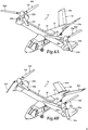
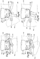
- tiltrotor aircraft 10 is depicted in various states during a transition between VTOL flight mode and storage mode.
- Aircraft 10 has a VTOL flight mode, as best seen in figure 2B , a forward flight mode, as best seen in figure 2A , and a storage mode, as best seen in figure 4F .
- aircraft 10 includes fuselage 12 and wing 18 that is rotatably mounted to fuselage 12.
- Wing 18 is reversibly rotatable between a flight orientation that is generally perpendicular to fuselage 12, as best seen in figure 4A , and a stowed orientation that is generally parallel to fuselage 12, as best seen in figure 4F .
- Pylon assemblies 22a, 22b are positioned proximate the outboard ends of wing 18.
- Mast assemblies 24a, 24b are respectively rotatable relative to pylon assemblies 22a, 22b.
- Mast assemblies 24a, 24b are reversibly rotatable between a generally vertical orientation, as best seen in figure 4A , and a generally horizontal orientation, as best seen in figure 4F .
- Proprotor assemblies 26a, 26b are respectively rotatable relative to mast assemblies 24a, 24b.
- Proprotor assembly 26a includes rotor blades 52a, 52b, 52c and proprotor assembly 26b includes rotor blades 52d, 52e, 52f.
- Proprotor assemblies 26a, 26b each have a radially extended orientation, as best seen in figure 4A , and a stowed orientation, as best seen in figure 4F . More specifically in the stowed orientation, rotor blade 52a of proprotor assembly 26a is folded beamwise below wing 18 and generally conforming with pylon assembly 22a and rotor blade 52d of proprotor assembly 26b is folded beamwise below wing 18 and generally conforming with pylon assembly 22b.
- Rotor blades 52b, 52c of proprotor assembly 26a are folded beamwise above wing 18 and generally conforming with pylon assembly 22a and rotor blades 52e, 52f of proprotor assembly 26b are folded beamwise above wing 18 and generally conforming with pylon assembly 22b.
- rotation of mast assembly 24a relative to pylon assembly 22a is independent of rotation mast assembly 24b relative to pylon assembly 22b.
- rotation of mast assembly 24a relative to pylon assembly 22a is independent of rotation of rotor blades 52a, 52b, 52c relative to rotor hub 54.
- rotation of rotor blade 52a relative to rotor hub 54 is independent of rotation of rotor blade 52b and independent of rotation of rotor blade 52c relative to rotor hub 54.
- aircraft 10 is best characterized as being in VTOL flight mode.
- wing 18 is in flight orientation, generally perpendicular to fuselage 12.
- Mast assemblies 24a, 24b are each in a generally vertical orientation.
- Proprotor assemblies 26a, 26b are each in a radially extended orientation.
- Tail members 16a, 16b are in a dihedral orientation.
- Rotor blades 52a, 52b, 52c have been collectively operated to have a generally horizontal orientation.
- Rotor blades 52d, 52e, 52f have been collectively operated to have a generally horizontal orientation.
- FIG 4B the conversion from VTOL flight mode to storage mode has begun.
- wing 18 remains in flight orientation, generally perpendicular to fuselage 12.
- Mast assemblies 24a, 24b have rotated approximately 30 degrees from the vertical orientation toward the horizontal orientation.
- Tail members 16a, 16b have begun to lower.
- Rotor blades 52a, 52b have begun to fold beamwise, while rotor blade 52c remains radially extended.
- Rotor blades 52d, 52e have begun to fold beamwise, while rotor blade 52f remains radially extended.
- wing 18 remains in flight orientation, generally perpendicular to fuselage 12.
- Mast assemblies 24a, 24b have rotated approximately 45 degrees from the vertical orientation toward the horizontal orientation.
- Tail members 16a, 16b continue to lower.
- Rotor blades 52a, 52b continue to fold, while rotor blade 52c remains radially extended.
- Rotor blades 52d, 52e continue to fold, while rotor blade 52f remains radially extended.
- Proprotor assemblies 26a, 26b have counter rotated approximately 30 degrees such that rotor blades 52c, 52f are inboardly extended generally parallel with wing 18.
- Rotor blades 52a, 52d have cleared pylon assemblies 22a, 22b and are generally vertical having sufficient ground clearance to continue folding.
- FIG 4D the conversion from VTOL flight mode to storage mode continues.
- wing 18 remains in flight orientation, generally perpendicular to fuselage 12.
- Mast assemblies 24a, 24b have rotated approximately 60 degrees from the vertical orientation toward the horizontal orientation.
- Tail members 16a, 16b continue to lower.
- Rotor blades 52a, 52b continue to fold, while rotor blade 52c remains radially extended until sufficient clearance with wing 18 is established allowing rotor blade 52c to begin beamwise folding.
- Rotor blades 52d, 52e continue to fold, while rotor blade 52f remains radially extended until sufficient clearance with wing 18 is established allowing rotor blade 52f to begin beamwise folding.
- FIG 4E the conversion from VTOL flight mode to storage mode continues.
- wing 18 has rotated approximately 45 degrees relative to fuselage 12.
- Mast assemblies 24a, 24b have rotated to the horizontal orientation.
- Tail members 16a, 16b are fully lowered to an anhedral orientation.
- Rotor blade 52a is in a stowed orientation beneath wing 18 and generally conforming with pylon assembly 22a.
- Rotor blades 52b, 52c are each in a stowed orientation above wing 18 and generally conforming with pylon assembly 22a.
- Rotor blade 52d is in a stowed orientation beneath wing 18 and generally conforming with pylon assembly 22b.
- Rotor blades 52e, 52f are each in a stowed orientation above wing 18 and generally conforming with pylon assembly 22b.
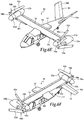
- FIG 4F the conversion from VTOL flight mode to storage mode is complete.
- wing 18 is in stowed orientation, generally parallel to fuselage 12.
- Mast assemblies 24a, 24b are in the horizontal orientation.
- Tail members 16a, 16b are fully lowered to the anhedral orientation.
- Rotor blade 52a is in a stowed orientation beneath wing 18 and generally conforming with pylon assembly 22a.
- Rotor blades 52b, 52c are each in a stowed orientation above wing 18 and generally conforming with pylon assembly 22a.
- Rotor blade 52d is in a stowed orientation beneath wing 18 and generally conforming with pylon assembly 22b.
- Rotor blades 52e, 52f are each in a stowed orientation above wing 18 and generally conforming with pylon assembly 22b.
- the storage mode of aircraft 10 depicted and described with reference to figures 4A-4F significantly reduces the footprint of aircraft 10 as compared to the flight modes of aircraft 10.
- the stowed orientation of the rotor blades does not result in an undesirably large moment being placed on the drive systems.
- a reverse sequence may be followed to avoid contact between the various components of aircraft 10 with each other as well as to avoid contact between the various components of aircraft 10 and the surface on which aircraft 10 rests.
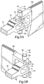
- FIG. 5A-5B of the drawings the beamwise folding operation of a rotor blade is more fully described.
- the hingeable relationship of rotor blade 52a to rotor hub 54 is substantially similar to the hingeable relationship between each rotor blade and the respective rotor hub therefore, for sake of efficiency, certain features will be disclosed only with regard to rotor blade 52a and rotor hub 54.
- One having ordinary skill in the art will fully appreciate an understanding of the hingeable relationship between other rotor blades and rotor hubs based upon the disclosure herein of rotor blade 52a and rotor hub 54.
- rotor blade 52a is rotatably mounted to a grip assembly 70 of rotor hub 54 by a pair of spaced blade tangs 72a, 72b and a blade pivot pin 74, which extends therethrough.
- a drive motor 76 that has planetary gear reducers 78a, 78b mounted on each end thereof.
- Gear reducer 78a has an output that is coupled to blade tang 72a and gear reducer 78b has an output that is coupled to blade tang 72b such that rotor blade 52a moves responsive to operation of drive motor 76.
- drive motor 76 and gear reducers 78a, 78b form an actuation assembly depicted as rotary actuator 80 for rotating rotor blade 52a about axis of rotation 82.
- drive motor 76 reversibly operates to enable rotor blade 52a to be folded from the radially extended orientation to the stowed orientation and to be unfolded from the stowed orientation to the radially extended orientation.
- rotor blade 52a may be locked in the radially extended orientation and in the stowed orientation by rotary actuator 80 and/or additional locking mechanisms (not shown).
- tiltrotor aircraft 10 is depicted in various states during a transition between VTOL flight mode and storage mode.
- Aircraft 10 has a VTOL flight mode, as best seen in figure 2B , a forward flight mode, as best seen in figure 2A , and a storage mode, as best seen in figure 6F .
- aircraft 10 includes fuselage 12 and wing 18 that is rotatably mounted to fuselage 12.
- Wing 18 is reversibly rotatable between a flight orientation that is generally perpendicular to fuselage 12, as best seen in figure 6A , and a stowed orientation that is generally parallel to fuselage 12, as best seen in figure 6F .
- Pylon assemblies 22a, 22b are positioned proximate the outboard ends of wing 18.
- Mast assemblies 24a, 24b are respectively rotatable relative to pylon assemblies 22a, 22b.
- Mast assemblies 24a, 24b are reversibly rotatable between a generally vertical orientation, as best seen in figure 6A , and a generally horizontal orientation, as best seen in figures 6B-6F .
- Proprotor assemblies 90a, 90b are respectively rotatable relative to mast assemblies 24a, 24b.
- Proprotor assembly 90a includes rotor blades 92a, 92b, 92c and proprotor assembly 90b includes rotor blades 92d, 92e, 92f.
- Proprotor assemblies 90a, 90b each have a radially extended orientation, as best seen in figure 6A , and a stowed orientation, as best seen in figure 6F . More specifically in the stowed orientation, rotor blade 92a of proprotor assembly 90a is folded chordwise below wing 18 and generally conforming with pylon assembly 22a and rotor blade 92d of proprotor assembly 90b is folded chordwise below wing 18 and generally conforming with pylon assembly 22b. Rotor blade 92b of proprotor 90a is folded chordwise above wing 18 and generally conforming with pylon assembly 22a and rotor blade 92e of proprotor 90b is folded chordwise above wing 18 and generally conforming with pylon assembly 22b. Rotor blade 92c of proprotor 90a is inboardly extended generally parallel with wing 18 and rotor blade 92f of proprotor 90b is inboardly extended generally parallel with wing 18.
- aircraft 10 is best characterized as being in VTOL flight mode.
- wing 18 is in flight orientation, generally perpendicular to fuselage 12.
- Mast assemblies 24a, 24b are each in a generally vertical orientation.
- Proprotor assemblies 90a, 90b are each in a radially extended orientation.
- Tail members 16a, 16b are in a dihedral orientation.
- Rotor blades 92a, 92b, 92c have been collectively operated to have a generally vertical or feathered orientation.
- Rotor blades 92d, 92e, 92f have been collectively operated to have a generally vertical or feathered orientation.
- FIG 6B the conversion from VTOL flight mode to storage mode has begun.
- wing 18 remains in flight orientation, generally perpendicular to fuselage 12.
- Mast assemblies 24a, 24b have rotated approximately 90 degrees to the horizontal orientation.
- Tail members 16a, 16b remains in the dihedral orientation.
- Rotor blades 92a, 92b, 92c remain radially extended.
- Rotor blades 92d, 92e, 92f remains radially extended.
- Proprotor assemblies 90a, 90b are positioned such that rotor blade 92b and rotor blade 92e each has a generally upwardly extending vertical orientation.
- FIG 6C the conversion from VTOL flight mode to storage mode continues.
- wing 18 remains in flight orientation, generally perpendicular to fuselage 12.
- Mast assemblies 24a, 24b are in the horizontal orientation.
- Tail members 16a, 16b remains in the dihedral orientation.
- Rotor blades 92a, 92d have been manually unlocked and partially folded to manually maintain ground clearance and clearance with pylon assemblies 22a, 22b.
- Rotor blades 92b, 92c, 92e, 92f remain radially extended.
- FIG 6D the conversion from VTOL flight mode to storage mode continues.
- wing 18 remains in flight orientation, generally perpendicular to fuselage 12.
- Mast assemblies 24a, 24b are in the horizontal orientation.
- Tail members 16a, 16b remains in the dihedral orientation.
- Proprotor assemblies 90a, 90b have counter rotated approximately 30 degrees such that rotor blades 92c, 92f are inboardly extending generally parallel with wing 18.
- Rotor blades 92a, 92d are now clear of pylon assemblies 22a, 22b and are folded and locked in a stowed orientation.
- Rotor blades 92b, 92c, 92e, 92f remain radially extended.
- FIG 6E the conversion from VTOL flight mode to storage mode continues.
- wing 18 remains in flight orientation, generally perpendicular to fuselage 12.
- Mast assemblies 24a, 24b are in the horizontal orientation.
- Tail members 16a, 16b remains in the dihedral orientation.
- Rotor blade 92a is in a stowed orientation beneath wing 18 and generally conforming with pylon assembly 22a.
- Rotor blade 92d is in a stowed orientation beneath wing 18 and generally conforming with pylon assembly 22b.
- Rotor blade 92b has been manually unlocked, folded and locked in a stowed orientation above wing 18 and generally conforming with pylon assembly 22a.
- Rotor blade 92e has been manually unlocked, folded and locked in a stowed orientation above wing 18 and generally conforming with pylon assembly 22b.
- Rotor blades 92c, 92f are each inboardly extending generally parallel with wing 18.
- FIG 6F the conversion from VTOL flight mode to storage mode is complete.
- wing 18 has been rotated approximately 90 degrees to a stowed orientation, generally parallel to fuselage 12.
- Mast assemblies 24a, 24b are in the horizontal orientation.
- Tail members 16a, 16b are fully lowered to an anhedral orientation.
- Rotor blade 92a is in a stowed orientation beneath wing 18 and generally conforming with pylon assembly 22a.
- Rotor blade 92d is in a stowed orientation beneath wing 18 and generally conforming with pylon assembly 22b.
- Rotor blade 92b is in a stowed orientation above wing 18 and generally conforming with pylon assembly 22a.
- Rotor blade 92e is in a stowed orientation above wing 18 and generally conforming with pylon assembly 22b.
- Rotor blades 92c, 92f are each inboardly extending generally parallel with wing 18 in a stowed orientation.
- the storage mode of aircraft 10 depicted and described with reference to figures 6A-6F significantly reduces the footprint of aircraft 10 as compared to the flight modes of aircraft 10.
- the stowed orientation of the rotor blades does not result in an undesirably large moment being placed on the drive systems.
- a reverse sequence may be followed to avoid contact between the various components of aircraft 10 with each other as well as to avoid contact between the various components of aircraft 10 and the surface on which aircraft 10 rests.
- FIG. 7A-10D the chordwise folding operation of a rotor blade is more fully described.
- the hingeable relationship of rotor blade 92a to rotor hub 94a is substantially similar to the hingeable relationship between each rotor blade and the respective rotor hub therefore, for sake of efficiency, certain features will be disclosed only with regard to rotor blade 92a and rotor hub 94a.
- One having ordinary skill in the art will fully appreciate an understanding of the hingeable relationship between other rotor blades and rotor hubs based upon the disclosure herein of rotor blade 92a and rotor hub 94a.
- rotor hub 94a includes a pitch horn 100, a leading fairing 102 and a trailing fairing 104, as best see in figures 7A-7B .
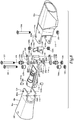
- rotor hub 94a includes a grip assembly 106 and a harness 108 that are coupled together with connectors 110a, 110b along axis 112, as best seen in figure 8 .
- axis 112 labeled in figure 8 , which symbolize that the instance of axis 112 extending through grip assembly 106 and the instance of axis 112 extending through harness 108 are a common axis when rotor hub 94a is fully assembled, wherein harness 108 is at least partially disposed within grip assembly 106. It is accordingly to be understood by those having ordinary skill in the art that this common axis convention will be used throughout figure 8 .
- Rotor blade 92a is rotatably coupled to grip assembly 106 and harness 108 about pivot pin 116 that extends along axis 114.
- spacers 118a, 118b are sandwiched between grip assembly arms 106a, 106b and harness 108 along axis 114 and grip assembly arms 106a, 106b are sandwiched between blade tangs 120a, 120b such that pivot pin 116 passes through blade tang 120a, grip assembly arm 106a, spacer 118a, harness 108, spacer 118b, grip assembly arm 106b and blade tang 120b.
- a nut 122 is threadably coupled to pivot pin 116 to secure rotor blade 92a, grip assembly 106 and harness 108 together.
- Rotor blade 92a is secured in the radially extended orientation, as best seen in figures 7A , 9A and 10A , by a lock assembly depicted as release pin 124 that extends along axis 126.
- a lock assembly depicted as release pin 124 that extends along axis 126.
- bushings 128a, 128b are sandwiched between grip assembly arms 106a, 106b and harness 108 along axis 126 and grip assembly arms 106a, 106b are sandwiched between blade tangs 120a, 120b such that release pin 124 passes through blade tang 120a, grip assembly arm 106a, bushing 128a, harness 108, bushing 128b, grip assembly arm 106b and blade tang 120b.
- a nut 130 is threadably coupled to release pin 124 to prevent rotor blade 92a from rotating relative to grip assembly 106 and harness 108 when rotor blade 92a is in the radially extended orientation for flight modes of aircraft 10.
- a linkage assembly 132 is rotatably coupled to harness 108 and is rotatably coupled to rotor blade 92a.
- Linkage assembly 132 includes tow links 134a, 134b, a latch pin 136 and a drag link 138.
- tow links 134a, 134b are rotatable about axis 126 as tow links 134a, 134b are respectively positioned on bearing surfaces 140a, 104b of bushings 128a, 128b.
- Tow links 134a, 134b rotatably coupled to drag link 138 via latch pin 136 along axis 142.
- tow links 134a, 134b are sandwiched between drag link arms 138a, 138b with latch pin 136 extending therethrough.
- Drag link 138 is rotatably coupled to rotor blade 92a by linkage pin 144.
- drag link 138 is sandwiched between spacers 148a, 148b and between blade tangs 120a, 120b such that linkage pin 144 passes through blade tang 120a, spacer 148a, drag link 138, spacer 148b and blade tang 120b.
- a nut 150 is threadably coupled to linkage pin 144 to secure rotor blade 92a and drag link 138 together.
- Pawl assembly 152 includes a pawl member 152a that is coupled to harness 108 by pin 154a in receiving region 156 of harness 108.
- Pawl assembly 152 also includes a pawl member 152b that is coupled to harness 108 by pin 154b in receiving region 158 of pawl member 152a and receiving region 156 of harness 108.
- rotor blade 92a is secured to grip assembly 106 and harness 108 in the radially extended orientation by pivot pin 116 and release pin 124.
- This configuration of rotor blade 92a relative to grip assembly 106 and harness 108 is used for flight modes of tiltrotor aircraft 10.
- rotor blade 92a is folded chordwise relative to grip assembly 106 and harness 108.
- release pin 124 is removed from its connection with rotor blade 92a, grip assembly 106 and harness 108, which may be a manual process.
- rotor blade 92a is operable to rotate about pivot pin 116 relative to grip assembly 106 and harness 108, which may be a manual process. As best seen in figures 9B and 10B , rotor blade 92a has rotated approximately 20 degrees relative to grip assembly 106 and harness 108. It is noted that linkage assembly 132 is moving from a contracted orientation to an extended orientation as rotor blade 92a rotates relative to grip assembly 106 and harness 108. The extension of linkage assembly 132 is a result of tow links 134a, 134b rotating about bearing surfaces 140a, 104b of bushings 128a, 128b, which remain coupled to harness 108 without the requirement of release pin 124 extending therethrough.
- rotor blade 92a has rotated approximately 70 degrees relative to grip assembly 106 and harness 108 as linkage assembly 132 continues to be extended between rotor blade 92a and harness 108.
- latch pin 136 of linkage assembly 132 is approaching pawl assembly 152.
- rotor blade 92a has rotated approximately 90 degrees relative to grip assembly 106 and harness 108 as linkage assembly 132 continues to be extended between rotor blade 92a and harness 108.
- Rotor blade 92a is now in the stowed orientation.
- latch pin 136 of linkage assembly 132 has engaged pawl assembly 152, which now locks rotor blade 92a in the stowed orientation relative to the harness 108. More specifically, as latch pin 136 of linkage assembly 132 engages pawl assembly 152, latch pin 136 passes across pawl member 152b and enters a receiving region 160 of harness 108. Once latch pin 136 enters region 160, pawl member 152b prevent latch pin 136 from exiting region 160 and thus locks rotor blade 92a in the stowed orientation relative to the harness 108.
- rotor blade 92a When it is desired to return aircraft 10 to flight mode, rotor blade 92a is unfolded chordwise relative to grip assembly 106 and harness 108. As a first step, pawl member 152a is depressed to eject latch pin 136 from region 160 of harness 108, which may be a manual process. In this configuration, rotor blade 92a is operable to rotate about pivot pin 116 relative to grip assembly 106 and harness 108 such that rotor blade 92a may be returned to the radially extended orientation, which may be a manual process. It is noted that linkage assembly 132 is moving from the extended orientation to the contracted orientation as rotor blade 92a rotates relative to grip assembly 106 and harness 108.
- release pin 124 may be reinserted through blade tang 120a, grip assembly arm 106a, bushing 128a, harness 108, bushing 128b, grip assembly arm 106b and blade tang 120b.
- Nut 130 may now be threadably coupled to release pin 124 to secure rotor blade 92a in the radially extended orientation for flight modes of aircraft 10.
- Aircraft 210 includes a fuselage 212, a wing mount assembly 214 that is rotatable relative to fuselage 212 and a tail assembly 216 including rotatably mounted tail members 216a, 216b having control surfaces operable for horizontal and/or vertical stabilization during forward flight.
- a wing member 218 is supported by wing mount assembly 214 and rotates with wing mount assembly 214 relative to fuselage 212 as discussed herein.
- propulsion assemblies 220a, 220b Located at outboard ends of wing member 218 are propulsion assemblies 220a, 220b.
- Propulsion assembly 220a includes a nacelle depicted as fixed pylon 222a that houses an engine and transmission.
- propulsion assembly 220a includes a mast assembly 224a that is rotatable relative to fixed pylon 222a between a generally horizontal orientation, as best seen in figure 11A , a generally vertical orientation, as best seen in figure 11B .
- Propulsion assembly 220a also includes a proprotor assembly 226a that is rotatable relative to mast assembly 224a responsive to torque and rotational energy provided via a rotor hub assembly and drive system mechanically coupled to the engine and transmission.
- propulsion assembly 220b includes a nacelle depicted as fixed pylon 222b that houses an engine and transmission, a mast assembly 224b that is rotatable relative to fixed pylon 222b and a proprotor assembly 226b that is rotatable relative to mast assembly 224b responsive to torque and rotational energy provided via a rotor hub assembly and drive system mechanically coupled to the engine and transmission.
- Figure 11A illustrates aircraft 210 in airplane or forward flight mode, in which proprotor assemblies 226a, 226b are rotating in a substantially vertical plane to provide a forward thrust enabling wing member 218 to provide a lifting force responsive to forward airspeed, such that aircraft 210 flies much like a conventional propeller driven aircraft.
- Figure 11B illustrates aircraft 210 in helicopter or VTOL flight mode, in which proprotor assemblies 226a, 226b are rotating in a substantially horizontal plane to provide a lifting thrust, such that aircraft 210 flies much like a conventional helicopter. It should be appreciated that aircraft 210 can be operated such that proprotor assemblies 226a, 226b are selectively positioned between forward flight mode and VTOL flight mode, which can be referred to as a conversion flight mode.
- proprotor assemblies 226a, 226b each include three twisted rotor blades that are equally spaced apart circumferentially at approximately 120 degree intervals. It should be understood by those having ordinary skill in the art, however, that proprotor assemblies 226a, 226b of the present disclosure could have rotor blades with other designs and other configurations.
- proprotor assemblies 226a, 226b rotate in opposite directions to provide torque balancing to aircraft 210. For example, when viewed from the front of aircraft 210 in forward flight mode, proprotor assembly 226a rotates clockwise and proprotor assembly 226b rotates counterclockwise.
- proprotor assemblies 226a, 226b rotate 60 degrees out of phase with each other such that rotor blades of alternating proprotor assemblies 226a, 226b sequentially pass wing member 218 during all modes of operation of aircraft 210.
- proprotor assemblies 226a, 226b are mechanically coupled to a common interconnect drive shaft such that proprotor assemblies 226a, 226b have matched counter rotation wherein any rotation of one proprotor assembly 226a, 226b results in an equal counter rotation of the other of proprotor assembly 226a, 226b.
- tiltrotor aircraft 210 is depicted in various states during a transition between VTOL flight mode and storage mode.
- Aircraft 210 has a VTOL flight mode, as best seen in figure 11B , a forward flight mode, as best seen in figure 11A , and a storage mode, as best seen in figure 12F .
- aircraft 210 includes fuselage 212 and wing 218 that is rotatably mounted to fuselage 212.
- Wing 218 is reversibly rotatable between a flight orientation that is generally perpendicular to fuselage 212, as best seen in figure 12A , and a stowed orientation that is generally parallel to fuselage 212, as best seen in figure 12F .
- Pylon assemblies 222a, 222b are positioned proximate the outboard ends of wing 218.
- Mast assemblies 224a, 224b are respectively rotatable relative to pylon assemblies 222a, 222b.
- Mast assemblies 224a, 224b are reversibly rotatable between a generally vertical orientation, as best seen in figure 12A , and a generally horizontal orientation, as best seen in figure 12F .
- Proprotor assemblies 226a, 226b are respectively rotatable relative to mast assemblies 224a, 224b.
- Proprotor assembly 226a includes rotor blades 228a, 228b, 228c and proprotor assembly 226b includes rotor blades 228d, 228e, 228f.
- Proprotor assemblies 226a, 226b each have a radially extended orientation, as best seen in figure 12A , and a stowed orientation, as best seen in figure 12F . More specifically in the stowed orientation, rotor blades 228a, 228b of proprotor assembly 226a are folded beamwise to be generally parallel with rotor blade 228c and rotor blades 228d, 228e of proprotor assembly 226b are folded beamwise to be generally parallel with rotor blade 228f.
- rotor blades 228a, 228b, 228c of proprotor assembly 226a have an ascending orientation relative to wing 218 and rotor blades 228d, 228e, 228f of proprotor assembly 226b have a descending orientation relative to wing 218.
- rotor blades 228a, 228b, 228c of proprotor assembly 226a ascend at an angle of approximately 30 degrees relative to wing 218 and rotor blades 228d, 228e, 228f of proprotor assembly 226b descend at an angle of approximately 30 degrees relative to wing 218.
- aircraft 210 is best characterized as being in VTOL flight mode.
- wing 218 is in flight orientation, generally perpendicular to fuselage 212.
- Mast assemblies 224a, 224b are each in a generally vertical orientation.
- Proprotor assemblies 226a, 226b are each in a radially extended orientation.
- Tail members 216a, 216b are in a dihedral orientation.
- Rotor blades 228a, 228b, 228c have been collectively operated to have a generally vertical orientation.
- Rotor blades 228d, 228e, 228f have been collectively operated to have a generally vertical orientation.
- FIG 12B the conversion from VTOL flight mode to storage mode has begun.
- wing 218 remains in flight orientation, generally perpendicular to fuselage 212.
- Mast assemblies 224a, 224b remain in the vertical orientation.
- Tail members 216a, 216b have begun to lower.
- Rotor blades 228a, 228b have begun to fold beamwise, while rotor blade 228c remains radially extended.
- Rotor blades 228d, 228e have begun to fold beamwise, while rotor blade 228f remains radially extended.
- Proprotor assemblies 226a, 226b have counter rotated approximately 30 degrees.
- FIG 12C the conversion from VTOL flight mode to storage mode continues.
- wing 218 has rotated approximately 30 degrees relative to fuselage 212.
- Mast assemblies 224a, 224b remain in the vertical orientation.
- Tail members 216a, 216b continue to lower.
- Rotor blades 228a, 228b continue to fold, while rotor blade 228c remains radially extended.
- Rotor blades 228d, 228e continue to fold, while rotor blade 228f remains radially extended.
- FIG 12D the conversion from VTOL flight mode to storage mode continues.
- wing 218 has rotated approximately 60 degrees relative to fuselage 212.
- Mast assemblies 224a, 224b have rotated approximately 30 degrees from the vertical orientation toward the horizontal orientation.
- Tail members 216a, 216b continue to lower.
- Rotor blades 228a, 228b continue to fold, while rotor blade 228c remains radially extended.
- Rotor blades 228d, 228e continue to fold, while rotor blade 228f remains radially extended.
- FIG 12E the conversion from VTOL flight mode to storage mode continues.
- wing 218 has rotated approximately 80 degrees relative to fuselage 212.
- Mast assemblies 224a, 224b have rotated approximately 60 degrees from the vertical orientation toward the horizontal orientation.
- Tail members 216a, 216b continue to lower.
- Rotor blades 228a, 228b are folded, while rotor blade 228c remains radially extended.
- Rotor blades 228d, 228e are folded, while rotor blade 228f remains radially extended.
- FIG 12F the conversion from VTOL flight mode to storage mode is complete.
- wing 218 is in stowed orientation, generally parallel to fuselage 212.
- Mast assemblies 224a, 224b are in the horizontal orientation.
- Tail members 216a, 216b are fully lowered to the anhedral orientation.
- Rotor blades 228a, 228b are in the stowed orientation folded relative to rotor blade 228c, which remains radially extended.
- Rotor blades 228d, 228e are in the stowed orientation folded relative to rotor blade 228f, which remains radially extended.
- rotor blades 228a, 228b, 228c of proprotor assembly 226a have an ascending orientation relative to wing 218 and rotor blades 228d, 228e, 228f of proprotor assembly 226b have a descending orientation relative to wing 218.
- the storage mode of aircraft 210 depicted and described with reference to figures 12A-12F significantly reduces the footprint of aircraft 210 as compared to the flight modes of aircraft 210.
- the stowed orientation of the rotor blades does not result in an undesirably large moment being placed on the drive systems.
- a reverse sequence may be followed to avoid contact between the various components of aircraft 210 with each other as well as to avoid contact between the various components of aircraft 210 and the surface on which aircraft 210 rests.
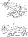
- tiltrotor aircraft 210 is depicted in various states during a transition between VTOL flight mode and storage mode.
- Aircraft 210 has a VTOL flight mode, as best seen in figure 11B , a forward flight mode, as best seen in figure 11A , and a storage mode, as best seen in figure 13F .
- aircraft 210 includes fuselage 212 and wing 218 that is rotatably mounted to fuselage 212.
- Wing 218 is reversibly rotatable between a flight orientation that is generally perpendicular to fuselage 212, as best seen in figure 13A , and a stowed orientation that is generally parallel to fuselage 212, as best seen in figure 13F .
- Pylon assemblies 222a, 222b are positioned proximate the outboard ends of wing 218.
- Mast assemblies 224a, 224b are respectively rotatable relative to pylon assemblies 222a, 222b.
- Mast assemblies 224a, 224b are reversibly rotatable between a generally vertical orientation, as best seen in figure 13A , and a generally horizontal orientation, as best seen in figure 13F .
- Proprotor assemblies 226a, 226b are respectively rotatable relative to mast assemblies 224a, 224b.
- Proprotor assembly 226a includes rotor blades 228a, 228b, 228c and proprotor assembly 226b includes rotor blades 228d, 228e, 228f.
- Proprotor assemblies 226a, 226b each have a radially extended orientation, as best seen in figure 13A , and a stowed orientation, as best seen in figure 13F . More specifically in the stowed orientation, rotor blade 228a of proprotor assembly 226a is folded beamwise below wing 218 and generally conforming with pylon assembly 222a. Rotor blades 228b, 228c of proprotor assembly 226a are folded beamwise above wing 218 and generally conforming with pylon assembly 222a.
- Rotor blades 228d, 228e of proprotor assembly 226b are folded beamwise to be generally parallel with rotor blade 228f and rotor blades 228d, 228e, 228f of proprotor assembly 226b have a descending orientation relative to wing 218, wherein the descending orientation is an angle of approximately 30 degrees relative to wing 218.
- aircraft 210 is best characterized as being in VTOL flight mode.
- wing 218 is in flight orientation, generally perpendicular to fuselage 212.
- Mast assemblies 224a, 224b are each in a generally vertical orientation.
- Proprotor assemblies 226a, 226b are each in a radially extended orientation.
- Tail members 216a, 216b are in a dihedral orientation.
- Rotor blades 228a, 228b, 228c have been collectively operated to have a generally horizontal orientation.
- Rotor blades 228d, 228e, 228f have been collectively operated to have a generally vertical orientation.
- FIG 13B the conversion from VTOL flight mode to storage mode has begun.
- wing 218 remains in flight orientation, generally perpendicular to fuselage 212.
- Mast assembly 224a has rotated approximately 30 degrees from the vertical orientation toward the horizontal orientation.
- Mast assembly 224b remains in the vertical orientation.
- Tail members 216a, 216b have begun to lower.
- Rotor blades 228a, 228b have begun to fold beamwise, while rotor blade 228c remains radially extended.
- Rotor blades 228d, 228e have begun to fold beamwise, while rotor blade 228f remains radially extended.
- Proprotor assemblies 226a, 226b have counter rotated approximately 30 degrees.
- FIG 13C the conversion from VTOL flight mode to storage mode continues.
- wing 218 remains in flight orientation, generally perpendicular to fuselage 212.
- Mast assembly 224a has rotated approximately 60 degrees from the vertical orientation toward the horizontal orientation.
- Mast assembly 224b remains in the vertical orientation.
- Tail members 216a, 216b continue to lower.
- Rotor blades 228a, 228b continue to fold beamwise, while rotor blade 228c remains radially extended until sufficient clearance with wing 218 is established allowing rotor blade 228c to begin beamwise folding.
- Rotor blade 228a has cleared pylon assembly 222a and has sufficient ground clearance to continue folding.
- Rotor blades 228d, 228e continue to fold beamwise, while rotor blade 228f remains radially extended.
- FIG 13D the conversion from VTOL flight mode to storage mode continues.
- wing 218 has rotated approximately 45 degrees relative to fuselage 212.
- Mast assembly 224a has rotated approximately 90 degrees from the vertical orientation toward the horizontal orientation.
- Mast assembly 224b remains in the vertical orientation.
- Tail members 216a, 216b are fully lowered.
- Rotor blade 228a is in a stowed orientation beneath wing 218 and generally conforming with pylon assembly 222a.
- Rotor blades 228b, 228c are each in a stowed orientation above wing 218 and generally conforming with pylon assembly 222a.
- Rotor blades 228d, 228e continue to fold, while rotor blade 228f remains radially extended.
- FIG 13E the conversion from VTOL flight mode to storage mode continues.
- wing 218 has rotated approximately 80 degrees relative to fuselage 212.
- Mast assembly 224a is in the horizontal orientation.
- Mast assembly 224b has rotated approximately 60 degrees from the vertical orientation toward the horizontal orientation.
- Tail members 216a, 216b are fully lowered.
- Rotor blade 228a is in a stowed orientation beneath wing 218 and generally conforming with pylon assembly 222a.
- Rotor blades 228b, 228c are each in a stowed orientation above wing 218 and generally conforming with pylon assembly 222a.
- Rotor blades 228d, 228e are folded, while rotor blade 228f remains radially extended.
- wing 218 is in stowed orientation, generally parallel to fuselage 212.
- Mast assemblies 224a, 224b are in the horizontal orientation.
- Tail members 216a, 216b are fully lowered to the anhedral orientation.
- Rotor blade 228a is in a stowed orientation beneath wing 218 and generally conforming with pylon assembly 222a.
- Rotor blades 228b, 228c are each in a stowed orientation above wing 218 and generally conforming with pylon assembly 222a.
- Rotor blades 228d, 228e are in the stowed orientation folded relative to rotor blade 228f, which remains radially extended.
- rotor blades 228d, 228e, 228f of proprotor assembly 226b have a descending orientation relative to wing 218.
- the storage mode of aircraft 210 depicted and described with reference to figures 13A-13F significantly reduces the footprint of aircraft 210 as compared to the flight modes of aircraft 210.
- the stowed orientation of the rotor blades does not result in an undesirably large moment being placed on the drive systems.
- a reverse sequence may be followed to avoid contact between the various components of aircraft 210 with each other as well as to avoid contact between the various components of aircraft 210 and the surface on which aircraft 210 rests.
Landscapes
- Engineering & Computer Science (AREA)
- Aviation & Aerospace Engineering (AREA)
- Mechanical Engineering (AREA)
- Tires In General (AREA)
- Transmission Devices (AREA)
Abstract
Description
- The present disclosure relates, in general, to tiltrotor aircraft having a VTOL flight mode, a forward flight mode and a storage mode and, in particular, to systems and method of stowing the rotor blades and the wing of a tiltrotor aircraft to reduced the footprint of the tiltrotor aircraft in the storage mode.
- Fixed-wing aircraft, such as airplanes, are capable of flight using wings that generate lift responsive to the forward airspeed of the aircraft, which is generated by thrust from one or more jet engines or propellers. The wings generally have an airfoil cross section that deflects air downward as the aircraft moves forward, generating the lift force to support the aircraft in flight. Fixed-wing aircraft, however, typically require a runway that is hundreds or thousands of feet long for takeoff and landing.
- Unlike fixed-wing aircraft, vertical takeoff and landing (VTOL) aircraft do not require runways. Instead, VTOL aircraft are capable of taking off, hovering and landing vertically. One example of a VTOL aircraft is a helicopter which is a rotorcraft having one or more rotors that provide lift and thrust to the aircraft. The rotors not only enable hovering and vertical takeoff and landing, but also enable forward, backward and lateral flight. These attributes make helicopters highly versatile for use in congested, isolated or remote areas. Helicopters, however, typically lack the forward airspeed of fixed-wing aircraft due to the phenomena of retreating blade stall and advancing blade compression.
- Tiltrotor aircraft attempt to overcome this drawback by including a set of proprotors that can change their plane of rotation based on the operation being performed. Tiltrotor aircraft generate lift and propulsion using proprotors that are typically coupled to nacelles mounted near the ends of a fixed wing. The nacelles rotate relative to the fixed wing such that the proprotors have a generally horizontal plane of rotation in a VTOL flight mode and a generally vertical plane of rotation while cruising in a forward flight mode, wherein the fixed wing provides lift and the proprotors provide forward thrust. In this manner, tiltrotor aircraft combine the vertical lift capability of a helicopter with the speed and range of fixed-wing aircraft.
- It has been found, however, that tiltrotor aircraft may occupy a large footprint when not in use, such as during storage on an aircraft carrier flight deck. Accordingly, certain tiltrotor aircraft are operable to perform a conversion from flight mode to storage mode, as seen in prior art
figures 1A-1D . Infigure 1A , a tiltrotor aircraft is shown in VTOL flight mode with the nacelles positioned in a generally vertical orientation and with the proprotors operable for rotation in a generally horizontal plane. Infigure 1B , two of the rotor blades of each proprotor have been folded in the beamwise direction such that all blades are generally parallel to the wing. Infigure 1C , the nacelles have been rotated approximately ninety degrees relative to the wing to a generally horizontal orientation. Infigure 1D , the wing has been rotated approximately ninety degrees relative to the fuselage of the tiltrotor aircraft such that the wing is generally parallel with the fuselage. In the illustrated storage mode of the tiltrotor aircraft, its footprint has been minimized. It has been found, however, that storing a tiltrotor aircraft with the rotor blades fully cantilevered to one side of the drive system results in an undesirably large moment being placed on the drive system, which may cause damage to bearings or other components of the drive system. Accordingly, a need has arisen for improved storage modes for tiltrotor aircraft. - In a first aspect, the present disclosure is directed to a tiltrotor aircraft having a VTOL flight mode, a forward flight mode and a storage mode. The aircraft includes a fuselage and a wing rotatably mounted to the fuselage and having first and second outboard ends. The wing is reversibly rotatable between a flight orientation, generally perpendicular to the fuselage, in the flight modes, and a stowed orientation, generally parallel to the fuselage, in the storage mode. First and second pylon assemblies are respectively positioned proximate the first and second outboard ends of the wing. First and second mast assemblies are respectively rotatable relative to the first and second pylon assemblies. The first and second mast assemblies are reversibly rotatable between a generally vertical orientation, in the VTOL flight mode, and a generally horizontal orientation, in the forward flight mode and the storage mode. First and second proprotor assemblies are respectively rotatable relative to the first and second mast assemblies. The first and second proprotor assemblies each includes first, second and third rotor blades and each have a radially extended orientation, in the flight modes, and a stowed orientation, in the storage mode, wherein the first rotor blade of each proprotor assembly is folded beamwise below the wing generally conforming with the respective pylon assembly and the second and third rotor blades of each proprotor assembly are folded beamwise above the wing generally conforming with the respective pylon assembly.
- In some embodiments, first and second tail members may be mounted to the fuselage and may be reversibly rotatable between a dihedral orientation, in the flight modes, and an anhedral orientation, in the storage mode. In certain embodiments, the first proprotor assembly may rotate in phase with the second proprotor assembly and/or the first and second proprotor assemblies may have matched counter rotation. In some embodiments, each proprotor assembly may include a rotor hub to which the respective rotor blades are hingeably coupled thereto. In certain embodiments, each proprotor assembly may include a plurality of rotor blade actuators, such as rotary actuators, that are operable to reversibly rotate the respective rotor blades between the radially extended orientation and the stowed orientation. In some embodiments, each mast assembly may include a pitch control assembly that is operable to control a collective pitch of the rotor blades of the respective proprotor assembly. In certain embodiments, each pylon assemblies may include a conversion actuator, such as a linear actuator, that is operable to reversibly rotate the respective mast assembly between the generally vertical orientation and the generally horizontal orientation.
- In a second aspect, the present disclosure in directed to a method of converting a tiltrotor aircraft from a VTOL flight mode to a storage mode. The aircraft includes a fuselage, a wing rotatably mounted to the fuselage and having first and second outboard ends, first and second pylon assemblies respectively positioned proximate the first and second outboard ends of the wing, first and second mast assemblies respectively rotatable relative to the first and second pylon assemblies and first and second proprotor assemblies respectively rotatable relative to the first and second mast assemblies. The method includes rotating the first and second mast assemblies from a generally vertical orientation to a generally horizontal orientation; folding a first rotor blade of each proprotor assembly beamwise from a radially extended orientation to a stowed orientation beneath the wing and generally conforming with the respective pylon assembly; folding second and third rotor blades of each proprotor assembly beamwise from radially extended orientations to stowed orientations above the wing and generally conforming with the respective pylon assembly; and rotating the wing from a flight orientation, generally perpendicular to the fuselage, to a stowed orientation, generally parallel to the fuselage.
- The method may also include rotating first and second tail members mounted to the fuselage from a dihedral orientation to an anhedral orientation; counter rotating the proprotor assemblies, for example 30 degrees, during the step of folding the first rotor blade of each proprotor assembly beamwise from the radially extended orientation to the stowed orientation and/or collectively adjusting a pitch of the rotor blades of each proprotor assembly before the folding steps.
- The method may also involve performing at least a portion of the step of folding the first rotor blade of each proprotor assembly beamwise from the radially extended orientation to the stowed orientation while the first and second mast assemblies are being rotated from the generally vertical orientation to the generally horizontal orientation; performing at least a portion of the step of folding the second and third rotor blades of each proprotor assembly beamwise from radially extended orientations to stowed orientations while the first and second mast assemblies are being rotated from the generally vertical orientation to the generally horizontal orientation; performing at least a portion of the step of folding the first rotor blade of each proprotor assembly beamwise from the radially extended orientation to the stowed orientation while the wing is being rotated from the flight orientation, generally perpendicular to the fuselage, to the stowed orientation, generally parallel to the fuselage; performing at least a portion of the step of folding the second and third rotor blades of each proprotor assembly beamwise from radially extended orientations to stowed orientations while the wing is being rotated from the flight orientation, generally perpendicular to the fuselage, to the stowed orientation, generally parallel to the fuselage and/or performing at least a portion of the step of rotating the first and second mast assemblies from the generally vertical orientation to the generally horizontal orientation while the wing is being rotated from the flight orientation, generally perpendicular to the fuselage, to the stowed orientation, generally parallel to the fuselage.
- In a third aspect, the present disclosure is directed to a tiltrotor aircraft having a VTOL flight mode, a forward flight mode and a storage mode. The aircraft includes a fuselage and a wing rotatably mounted to the fuselage and having first and second outboard ends. The wing is reversibly rotatable between a flight orientation, generally perpendicular to the fuselage, in the flight modes, and a stowed orientation, generally parallel to the fuselage, in the storage mode. First and second pylon assemblies are respectively positioned proximate the first and second outboard ends of the wing. First and second mast assemblies are respectively rotatable relative to the first and second pylon assemblies. The first and second mast assemblies are reversibly rotatable between a generally vertical orientation, in the VTOL flight mode, and a generally horizontal orientation, in the forward flight mode and the storage mode. First and second proprotor assemblies are respectively rotatable relative to the first and second mast assemblies. The first and second proprotor assemblies each includes first, second and third rotor blades and each have a radially extended orientation, in the flight modes, and a stowed orientation, in the storage mode, wherein the first rotor blade of each proprotor assembly is folded chordwise below the wing generally conforming with the respective pylon assembly, the second rotor blade of each proprotor assembly is folded chordwise above the wing generally conforming with the respective pylon assembly and the third rotor blade of each proprotor assembly is inboardly extended generally parallel with the wing.
- In some embodiments, each proprotor assembly may include a plurality of rotor blade locking assemblies that are operable to enable reversible rotation, such as manual reversible rotation, of the respective rotor blades between the radially extended orientation and the stowed orientation. In certain embodiments, the rotor blade locking assemblies may be operable to lock the respective rotor blades in the stowed orientation.
- In a fourth aspect, the present disclosure in directed to a method of converting a tiltrotor aircraft from a VTOL flight mode to a storage mode. The aircraft includes a fuselage, a wing rotatably mounted to the fuselage and having first and second outboard ends, first and second pylon assemblies respectively positioned proximate the first and second outboard ends of the wing, first and second mast assemblies respectively rotatable relative to the first and second pylon assemblies and first and second proprotor assemblies respectively rotatable relative to the first and second mast assemblies. The method includes rotating the first and second mast assemblies from a generally vertical orientation to a generally horizontal orientation; positioning a first rotor blade of each proprotor assembly in a generally upwardly extending vertical orientation; folding a second rotor blade of each proprotor assembly chordwise from a radially extended orientation to an intermediate orientation; positioning a third rotor blade of each proprotor assembly in a inboardly extending generally parallel with the wing orientation; folding the second rotor blade of each proprotor assembly chordwise from the intermediate orientation to a stowed orientation beneath the wing and generally conforming with the respective pylon assembly; folding the first rotor blade of each proprotor assembly chordwise from a radially extended orientation to a stowed orientation above the wing and generally conforming with the respective pylon assembly; and rotating the wing from a flight orientation, generally perpendicular to the fuselage, to a stowed orientation, generally parallel to the fuselage.
- The method may also include counter rotating the proprotor assemblies between the steps of positioning the first rotor blade of each proprotor assembly in the generally upwardly extending vertical orientation and positioning the third rotor blade of each proprotor assembly in the inboardly extending generally parallel with the wing orientation; feathering the rotor blades of each proprotor assembly before the folding steps; manually folding the second rotor blade of each proprotor assembly chordwise from the radially extended orientation to the intermediate orientation; manually folding the second rotor blade of each proprotor assembly chordwise from the intermediate orientation to the stowed orientation; manually folding the first rotor blade of each proprotor assembly chordwise from the radially extended orientation to the stowed orientation and/or locking the first and second rotor blades of each proprotor assembly in the stowed orientations.
- In a fifth aspect, the present disclosure is directed to a tiltrotor aircraft having a VTOL flight mode, a forward flight mode and a storage mode. The aircraft includes a fuselage and a wing rotatably mounted to the fuselage and having first and second outboard ends. The wing is reversibly rotatable between a flight orientation, generally perpendicular to the fuselage, in the flight modes, and a stowed orientation, generally parallel to the fuselage, in the storage mode. First and second pylon assemblies are respectively positioned proximate the first and second outboard ends of the wing. First and second mast assemblies are respectively rotatable relative to the first and second pylon assemblies. The first and second mast assemblies are reversibly rotatable between a generally vertical orientation, in the VTOL flight mode, and a generally horizontal orientation, in the forward flight mode and the storage mode. First and second proprotor assemblies are respectively rotatable relative to the first and second mast assemblies. The first and second proprotor assemblies each includes first, second and third rotor blades and each have a radially extended orientation, in the flight modes, and a stowed orientation, in the storage mode, wherein the first and second rotor blades of each proprotor assembly are folded beamwise to be generally parallel with the respective third rotor blade, the rotor blades of the first proprotor assembly have an ascending orientation relative to the wing and the rotor blades of the second proprotor assembly a descending orientation relative to the wing.
- In some embodiments, in the storage mode, the first proprotor assembly may be positioned aft of the second proprotor assembly. In certain embodiments, the ascending orientation of the rotor blades of the first proprotor assembly relative to the wing may be an angle of approximately 30 degrees and the descending orientation of the rotor blades of the second proprotor assembly relative to the wing may be an angle of approximately 30 degrees. In some embodiments, the first proprotor assembly may rotate approximately 60 degrees out of phase with the second proprotor assembly.
- In a sixth aspect, the present disclosure in directed to a method of converting a tiltrotor aircraft from a VTOL flight mode to a storage mode. The aircraft includes a fuselage, a wing rotatably mounted to the fuselage and having first and second outboard ends, first and second pylon assemblies respectively positioned proximate the first and second outboard ends of the wing, first and second mast assemblies respectively rotatable relative to the first and second pylon assemblies and first and second proprotor assemblies respectively rotatable relative to the first and second mast assemblies. The method includes folding first and second rotor blades of each proprotor assembly beamwise to be generally parallel with a respective third rotor blade; rotating the wing from a flight orientation, generally perpendicular to the fuselage, to a stowed orientation, generally parallel to the fuselage; rotating the first and second mast assemblies from a generally vertical orientation to a generally horizontal orientation; and counter rotating the first and second proprotor assemblies such that the rotor blades of the first proprotor assembly have an ascending orientation relative to the wing and the rotor blades of the second proprotor assembly have a descending orientation relative to the wing.
- The method may also include counter rotating the first and second proprotor assemblies such that the ascending orientation of the rotor blades of the first proprotor assembly relative to the wing may be an angle of approximately 30 degrees and the descending orientation of the rotor blades of the second proprotor assembly relative to the wing may be an angle of approximately 30 degrees and/or positioning the first proprotor assembly aft of the second proprotor assembly.
- The method may also involve performing at least a portion of the step of folding the first and second rotor blades of each proprotor assembly beamwise to be generally parallel with the respective third rotor blade while the first and second proprotor assemblies are being counter rotated; performing at least a portion of the step of folding the first and second rotor blades of each proprotor assembly beamwise to be generally parallel with the respective third rotor blade while the wing is being rotated from the flight orientation, generally perpendicular to the fuselage, to the stowed orientation, generally parallel to the fuselage and/or performing the step of folding the first and second rotor blades of each proprotor assembly beamwise to be generally parallel with the respective third rotor blade before rotating the first and second mast assemblies from the generally vertical orientation to the generally horizontal orientation.
- In a seventh aspect, the present disclosure is directed to a tiltrotor aircraft having a VTOL flight mode, a forward flight mode and a storage mode. The aircraft includes a fuselage and a wing rotatably mounted to the fuselage and having first and second outboard ends. The wing is reversibly rotatable between a flight orientation, generally perpendicular to the fuselage, in the flight modes, and a stowed orientation, generally parallel to the fuselage, in the storage mode. First and second pylon assemblies are respectively positioned proximate the first and second outboard ends of the wing. First and second mast assemblies are respectively rotatable relative to the first and second pylon assemblies. The first and second mast assemblies are reversibly rotatable between a generally vertical orientation, in the VTOL flight mode, and a generally horizontal orientation, in the forward flight mode and the storage mode. First and second proprotor assemblies are respectively rotatable relative to the first and second mast assemblies. The first and second proprotor assemblies each includes first, second and third rotor blades and each have a radially extended orientation, in the flight modes, and a stowed orientation, in the storage mode, wherein the first rotor blade of the first proprotor assembly is folded beamwise below the wing generally conforming with the respective pylon assembly, the second and third rotor blades of the first proprotor assembly are folded beamwise above the wing generally conforming with the respective pylon assembly, the first and second rotor blades of the second proprotor assembly are folded beamwise to be generally parallel with the third rotor blade of the second proprotor assembly and the rotor blades of the second proprotor assembly have a descending orientation relative to the wing.
- In an eighth aspect, the present disclosure in directed to a method of converting a tiltrotor aircraft from a VTOL flight mode to a storage mode. The aircraft includes a fuselage, a wing rotatably mounted to the fuselage and having first and second outboard ends, first and second pylon assemblies respectively positioned proximate the first and second outboard ends of the wing, first and second mast assemblies respectively rotatable relative to the first and second pylon assemblies and first and second proprotor assemblies respectively rotatable relative to the first and second mast assemblies. The method includes rotating the first and second mast assemblies from a generally vertical orientation to a generally horizontal orientation; folding a first rotor blade of the first proprotor assembly beamwise from a radially extended orientation to a stowed orientation beneath the wing and generally conforming with the respective pylon assembly; folding second and third rotor blades of the first proprotor assembly beamwise from radially extended orientations to stowed orientations above the wing and generally conforming with the respective pylon assembly; folding first and second rotor blades of the second proprotor assembly beamwise to be generally parallel with a third rotor blade of the second proprotor assembly; rotating the wing from a flight orientation, generally perpendicular to the fuselage, to a stowed orientation, generally parallel to the fuselage; and counter rotating the first and second proprotor assemblies such that the rotor blades of the second proprotor assembly have a descending orientation relative to the wing.
- The method may also involve performing at least a portion of the step of folding the first rotor blade of the first proprotor assembly beamwise from the radially extended orientation to the stowed orientation while the first mast assemblies is being rotated from the generally vertical orientation to the generally horizontal orientation; performing the step of rotating the first mast assembly from the generally vertical orientation to the generally horizontal orientation before rotating the second mast assembly from the generally vertical orientation to the generally horizontal orientation; performing at least a portion of the step of rotating the second mast assembly from the generally vertical orientation to the generally horizontal orientation while the wing is being rotated from the flight orientation, generally perpendicular to the fuselage, to the stowed orientation, generally parallel to the fuselage and/or performing the step of folding the first and second rotor blades of the second proprotor assembly beamwise to be generally parallel with the respective third rotor blade before rotating the second mast assembly from the generally vertical orientation to the generally horizontal orientation.
- For a more complete understanding of the features and advantages of the present disclosure, reference is now made to the detailed description along with the accompanying figures in which corresponding numerals in the different figures refer to corresponding parts and in which:
-
Figures 1A-1D are prior art drawings depicting a tiltrotor aircraft transitioning from a VTOL flight mode to a storage mode; -
Figures 2A-2B are schematic illustrations of an exemplary tiltrotor aircraft in forward flight mode and in VTOL flight mode in accordance with embodiments of the present disclosure; -
Figure 3A is an isometric view of an exemplary propulsion system for a tiltrotor aircraft in accordance with embodiments of the present disclosure; -
Figure 3B is a top view of an exemplary wing section of a tiltrotor aircraft in accordance with embodiments of the present disclosure; -
Figures 4A-4F are schematic illustrations of an exemplary tiltrotor aircraft transitioning between VTOL flight mode and storage mode in accordance with embodiments of the present disclosure; -
Figures 5A-5B are schematic illustrations of an actuation assembly operating a rotor blade between a radially extended orientation and a stowed orientation in accordance with embodiments of the present disclosure; -
Figures 6A-6F are schematic illustrations of an exemplary tiltrotor aircraft transitioning between VTOL flight mode and storage mode in accordance with embodiments of the present disclosure; -
Figures 7A-7B are schematic illustrations of a rotor blade in a radially extended orientation and a stowed orientation in accordance with embodiments of the present disclosure; -
Figure 8 is an exploded view of a rotor blade hinging and locking assembly for manually operating a rotor blade between a radially extended orientation and a stowed orientation in accordance with embodiments of the present disclosure; -
Figures 9A-9D are top views of a rotor blade hinging and locking assembly for manually operating a rotor blade between a radially extended orientation and a stowed orientation in accordance with embodiments of the present disclosure; -
Figures 10A-10D are side views of a rotor blade hinging and locking assembly for manually operating a rotor blade between a radially extended orientation and a stowed orientation in accordance with embodiments of the present disclosure; -
Figures 11A-11B are schematic illustrations of an exemplary tiltrotor aircraft in forward flight mode and in VTOL flight mode in accordance with embodiments of the present disclosure; -
Figures 12A-12F are schematic illustrations of an exemplary tiltrotor aircraft transitioning between VTOL flight mode and storage mode in accordance with embodiments of the present disclosure; and -
Figures 13A-13F are schematic illustrations of an exemplary tiltrotor aircraft transitioning between VTOL flight mode and storage mode in accordance with embodiments of the present disclosure. - While the making and using of various embodiments of the present disclosure are discussed in detail below, it should be appreciated that the present disclosure provides many applicable inventive concepts, which can be embodied in a wide variety of specific contexts. The specific embodiments discussed herein are merely illustrative and do not delimit the scope of the present disclosure. In the interest of clarity, not all features of an actual implementation may be described in this specification. It will of course be appreciated that in the development of any such actual embodiment, numerous implementation-specific decisions must be made to achieve the developer's specific goals, such as compliance with system-related and business-related constraints, which will vary from one implementation to another. Moreover, it will be appreciated that such a development effort might be complex and time-consuming but would be a routine undertaking for those of ordinary skill in the art having the benefit of this disclosure.
- In the specification, reference may be made to the spatial relationships between various components and to the spatial orientation of various aspects of components as the devices are depicted in the attached drawings. However, as will be recognized by those skilled in the art after a complete reading of the present disclosure, the devices, members, apparatuses, and the like described herein may be positioned in any desired orientation. Thus, the use of terms such as "above," "below," "upper," "lower" or other like terms to describe a spatial relationship between various components or to describe the spatial orientation of aspects of such components should be understood to describe a relative relationship between the components or a spatial orientation of aspects of such components, respectively, as the device described herein may be oriented in any desired direction.
- Referring to
figures 2A-2B in the drawings, a tiltrotor aircraft is schematically illustrated and generally designated 10.Aircraft 10 includes afuselage 12, awing mount assembly 14 that is rotatable relative tofuselage 12 and atail assembly 16 including rotatably mountedtail members wing member 18 is supported bywing mount assembly 14 and rotates withwing mount assembly 14 relative tofuselage 12 as discussed herein. Located at outboard ends ofwing member 18 arepropulsion assemblies Propulsion assembly 20a includes a nacelle depicted as fixedpylon 22a that houses an engine and transmission. In addition,propulsion assembly 20a includes amast assembly 24a that is rotatable relative to fixedpylon 22a between a generally horizontal orientation, as best seen infigure 2A , a generally vertical orientation, as best seen infigure 2B .Propulsion assembly 20a also includes aproprotor assembly 26a that is rotatable relative tomast assembly 24a responsive to torque and rotational energy provided via a rotor hub assembly and drive system mechanically coupled to the engine and transmission. Likewise,propulsion assembly 20b includes a nacelle depicted as fixedpylon 22b that houses an engine and transmission, amast assembly 24b that is rotatable relative to fixedpylon 22b and aproprotor assembly 26b that is rotatable relative tomast assembly 24b responsive to torque and rotational energy provided via a rotor hub assembly and drive system mechanically coupled to the engine and transmission. -
Figure 2A illustratesaircraft 10 in airplane or forward flight mode, in whichproprotor assemblies wing member 18 to provide a lifting force responsive to forward airspeed, such thataircraft 10 flies much like a conventional propeller driven aircraft.Figure 2B illustratesaircraft 10 in helicopter or VTOL flight mode, in whichproprotor assemblies aircraft 10 flies much like a conventional helicopter. It should be appreciated thataircraft 10 can be operated such thatproprotor assemblies aircraft 10 has been described as having one engine in eachfixed pylon proprotor assemblies - In the illustrated embodiment,
proprotor assemblies proprotor assemblies proprotor assemblies aircraft 10. For example, when viewed from the front ofaircraft 10 in forward flight mode,proprotor assembly 26a rotates clockwise andproprotor assembly 26b rotates counterclockwise. In addition,proprotor assemblies proprotor assembly pass wing member 18 at the same time during all modes of operation ofaircraft 10. Further, as discussed herein,proprotor assemblies proprotor assemblies proprotor assembly proprotor assembly - Referring now to
figures 3A-3B ,propulsion assembly 20a is disclosed in further detail.Propulsion assembly 20a is substantially similar topropulsion assembly 20b therefore, for sake of efficiency, certain features will be disclosed only with regard topropulsion assembly 20a. One having ordinary skill in the art, however, will fully appreciate an understanding ofpropulsion assembly 20b based upon the disclosure herein ofpropulsion assembly 20a.Propulsion assembly 20a includes anengine 30 that is fixed relative towing 18. Anengine output shaft 32 transfers power fromengine 30 to aspiral bevel gearbox 34 that includes spiral bevel gears to change torque direction by 90 degrees fromengine 30 to a fixedgearbox 36 via a clutch. Fixedgearbox 36 includes a plurality of gears, such as helical gears, in a gear train that are coupled to aninterconnect drive shaft 38 and a quill shaft (not visible) that supplies torque to an input inspindle gearbox 40 ofproprotor gearbox 42. -
Interconnect drive shaft 38 provides a torque path that enables a single engine ofaircraft 10 to provide torque to bothproprotors interconnect drive shaft 38 has arotational axis 44 that is aft of aconversion axis 46 ofspindle gearbox 40.Conversion axis 46 is parallel to alengthwise axis 48 ofwing 18. In the illustrated embodiment,interconnect drive shaft 38 includes a plurality of segments that share commonrotational axis 44. The location ofinterconnect drive shaft 38 aft ofwing spar 50 provides for optimal integration with fixedgearbox 36 without interfering with the primary torque transfer in the quill shaft between fixedgearbox 36 andspindle gearbox 40. -
Engine 30 is housed and supported in fixedpylon 22a (seefigures 2A-2B ) that may include features such as an inlet, aerodynamic fairings and exhaust, as well as other structures and systems to support and facilitate the operation ofengine 30. Proprotor 26a ofpropulsion assembly 20a includes threerotor blades rotor hub 54.Rotor hub 54 is coupled to amast 56 that is coupled toproprotor gearbox 42. Together,spindle gearbox 40,proprotor gearbox 42 andmast 56 are part ofmast assembly 24a that rotates relative to fixedpylon 22a. In addition, it should be appreciated by those having ordinary skill in the art thatmast assembly 24a may include different or additional components, such as a pitch control assembly depicted asswashplate 58,actuators 60 andpitch links 62, whereinswashplate 58 is selectively actuated byactuators 60 to selectively control the collective pitch and the cyclic pitch ofrotor blades conversion actuator 64 of fixedpylon 22a, is operable to reversibly rotatemast assembly 24a relative to fixedpylon 22a, which in turn selectively positionsproprotor assembly 26a between forward flight mode, in whichproprotor assembly 26a is rotating in a substantially vertical plane, and VTOL flight mode, in whichproprotor assembly 26a is rotating in a substantially horizontal plane. - Referring next to
figures 4A-4F of the drawings,tiltrotor aircraft 10 is depicted in various states during a transition between VTOL flight mode and storage mode.Aircraft 10 has a VTOL flight mode, as best seen infigure 2B , a forward flight mode, as best seen infigure 2A , and a storage mode, as best seen infigure 4F . As discussed above,aircraft 10 includesfuselage 12 andwing 18 that is rotatably mounted tofuselage 12.Wing 18 is reversibly rotatable between a flight orientation that is generally perpendicular tofuselage 12, as best seen infigure 4A , and a stowed orientation that is generally parallel tofuselage 12, as best seen infigure 4F .Pylon assemblies wing 18.Mast assemblies pylon assemblies Mast assemblies figure 4A , and a generally horizontal orientation, as best seen infigure 4F .Proprotor assemblies mast assemblies Proprotor assembly 26a includesrotor blades proprotor assembly 26b includesrotor blades Proprotor assemblies figure 4A , and a stowed orientation, as best seen infigure 4F . More specifically in the stowed orientation,rotor blade 52a ofproprotor assembly 26a is folded beamwise belowwing 18 and generally conforming withpylon assembly 22a androtor blade 52d ofproprotor assembly 26b is folded beamwise belowwing 18 and generally conforming withpylon assembly 22b.Rotor blades proprotor assembly 26a are folded beamwise abovewing 18 and generally conforming withpylon assembly 22a androtor blades proprotor assembly 26b are folded beamwise abovewing 18 and generally conforming withpylon assembly 22b. - An example conversion operation of
aircraft 10 from VTOL flight mode to storage mode will now be described. During conversion processes, it is important to avoid contact between the various components ofaircraft 10 with each other as well as to avoid contact between the various components ofaircraft 10 and the surface on whichaircraft 10 rests. To achieve this result, certain of the conversion steps, or portions thereof, may need to be performed before or while other steps, or portions thereof, are being performed. These sequential and/or simultaneous operations are enabled by having individually controlled actuators operating to transition the various components ofaircraft 10 independent of one another. For example, rotation ofwing 18 relative tofuselage 12 is independent of rotation ofmast assembly 24a relative topylon assembly 22a. Likewise, rotation ofmast assembly 24a relative topylon assembly 22a is independent ofrotation mast assembly 24b relative topylon assembly 22b. Similarly, rotation ofmast assembly 24a relative topylon assembly 22a is independent of rotation ofrotor blades rotor hub 54. In addition, rotation ofrotor blade 52a relative torotor hub 54 is independent of rotation ofrotor blade 52b and independent of rotation ofrotor blade 52c relative torotor hub 54. As such, those having ordinary skill in the art will understand that all such operations may be controlled individually and independent of one another. Accordingly, the order of operations and sequencing thereof may take a variety of forms, each of which is considered to be within the scope of the present disclosure. - In
figure 4A ,aircraft 10 is best characterized as being in VTOL flight mode. As illustrated,wing 18 is in flight orientation, generally perpendicular tofuselage 12.Mast assemblies Proprotor assemblies Tail members Rotor blades Rotor blades figure 4B , the conversion from VTOL flight mode to storage mode has begun. As illustrated,wing 18 remains in flight orientation, generally perpendicular tofuselage 12.Mast assemblies Tail members Rotor blades rotor blade 52c remains radially extended.Rotor blades rotor blade 52f remains radially extended. - In
figure 4C , the conversion from VTOL flight mode to storage mode continues. As illustrated,wing 18 remains in flight orientation, generally perpendicular tofuselage 12.Mast assemblies Tail members Rotor blades rotor blade 52c remains radially extended.Rotor blades rotor blade 52f remains radially extended.Proprotor assemblies rotor blades wing 18.Rotor blades pylon assemblies figure 4D , the conversion from VTOL flight mode to storage mode continues. As illustrated,wing 18 remains in flight orientation, generally perpendicular tofuselage 12.Mast assemblies Tail members Rotor blades rotor blade 52c remains radially extended until sufficient clearance withwing 18 is established allowingrotor blade 52c to begin beamwise folding.Rotor blades rotor blade 52f remains radially extended until sufficient clearance withwing 18 is established allowingrotor blade 52f to begin beamwise folding. - In
figure 4E , the conversion from VTOL flight mode to storage mode continues. As illustrated,wing 18 has rotated approximately 45 degrees relative tofuselage 12.Mast assemblies Tail members Rotor blade 52a is in a stowed orientation beneathwing 18 and generally conforming withpylon assembly 22a.Rotor blades wing 18 and generally conforming withpylon assembly 22a.Rotor blade 52d is in a stowed orientation beneathwing 18 and generally conforming withpylon assembly 22b.Rotor blades wing 18 and generally conforming withpylon assembly 22b. Infigure 4F , the conversion from VTOL flight mode to storage mode is complete. As illustrated,wing 18 is in stowed orientation, generally parallel tofuselage 12.Mast assemblies Tail members Rotor blade 52a is in a stowed orientation beneathwing 18 and generally conforming withpylon assembly 22a.Rotor blades wing 18 and generally conforming withpylon assembly 22a.Rotor blade 52d is in a stowed orientation beneathwing 18 and generally conforming withpylon assembly 22b.Rotor blades wing 18 and generally conforming withpylon assembly 22b. - As illustrated, the storage mode of
aircraft 10 depicted and described with reference tofigures 4A-4F significantly reduces the footprint ofaircraft 10 as compared to the flight modes ofaircraft 10. In the illustrated storage mode ofaircraft 10, the stowed orientation of the rotor blades does not result in an undesirably large moment being placed on the drive systems. To returnaircraft 10 from storage mode to VTOL flight mode, a reverse sequence may be followed to avoid contact between the various components ofaircraft 10 with each other as well as to avoid contact between the various components ofaircraft 10 and the surface on whichaircraft 10 rests. - Referring to
figures 5A-5B of the drawings, the beamwise folding operation of a rotor blade is more fully described. The hingeable relationship ofrotor blade 52a torotor hub 54 is substantially similar to the hingeable relationship between each rotor blade and the respective rotor hub therefore, for sake of efficiency, certain features will be disclosed only with regard torotor blade 52a androtor hub 54. One having ordinary skill in the art, however, will fully appreciate an understanding of the hingeable relationship between other rotor blades and rotor hubs based upon the disclosure herein ofrotor blade 52a androtor hub 54. In the illustrated embodiment,rotor blade 52a is rotatably mounted to agrip assembly 70 ofrotor hub 54 by a pair of spacedblade tangs blade pivot pin 74, which extends therethrough. Mounted withinpivot pin 74 is adrive motor 76 that hasplanetary gear reducers Gear reducer 78a has an output that is coupled toblade tang 72a andgear reducer 78b has an output that is coupled toblade tang 72b such thatrotor blade 52a moves responsive to operation ofdrive motor 76. As illustrated, drivemotor 76 andgear reducers rotary actuator 80 for rotatingrotor blade 52a about axis ofrotation 82. In one implementation, drivemotor 76 reversibly operates to enablerotor blade 52a to be folded from the radially extended orientation to the stowed orientation and to be unfolded from the stowed orientation to the radially extended orientation. Preferably,rotor blade 52a may be locked in the radially extended orientation and in the stowed orientation byrotary actuator 80 and/or additional locking mechanisms (not shown). - Referring next to
figures 6A-6F of the drawings,tiltrotor aircraft 10 is depicted in various states during a transition between VTOL flight mode and storage mode.Aircraft 10 has a VTOL flight mode, as best seen infigure 2B , a forward flight mode, as best seen infigure 2A , and a storage mode, as best seen infigure 6F . As discussed above,aircraft 10 includesfuselage 12 andwing 18 that is rotatably mounted tofuselage 12.Wing 18 is reversibly rotatable between a flight orientation that is generally perpendicular tofuselage 12, as best seen infigure 6A , and a stowed orientation that is generally parallel tofuselage 12, as best seen infigure 6F .Pylon assemblies wing 18.Mast assemblies pylon assemblies Mast assemblies figure 6A , and a generally horizontal orientation, as best seen infigures 6B-6F .Proprotor assemblies mast assemblies Proprotor assembly 90a includesrotor blades proprotor assembly 90b includesrotor blades Proprotor assemblies figure 6A , and a stowed orientation, as best seen infigure 6F . More specifically in the stowed orientation,rotor blade 92a ofproprotor assembly 90a is folded chordwise belowwing 18 and generally conforming withpylon assembly 22a androtor blade 92d ofproprotor assembly 90b is folded chordwise belowwing 18 and generally conforming withpylon assembly 22b.Rotor blade 92b ofproprotor 90a is folded chordwise abovewing 18 and generally conforming withpylon assembly 22a androtor blade 92e ofproprotor 90b is folded chordwise abovewing 18 and generally conforming withpylon assembly 22b.Rotor blade 92c ofproprotor 90a is inboardly extended generally parallel withwing 18 androtor blade 92f ofproprotor 90b is inboardly extended generally parallel withwing 18. - An example conversion operation of
aircraft 10 from VTOL flight mode to storage mode will now be described, wherein folding of the rotor blades is preferably accomplished using a manual process. Infigure 6A ,aircraft 10 is best characterized as being in VTOL flight mode. As illustrated,wing 18 is in flight orientation, generally perpendicular tofuselage 12.Mast assemblies Proprotor assemblies Tail members Rotor blades Rotor blades figure 6B , the conversion from VTOL flight mode to storage mode has begun. As illustrated,wing 18 remains in flight orientation, generally perpendicular tofuselage 12.Mast assemblies Tail members Rotor blades Rotor blades Proprotor assemblies rotor blade 92b androtor blade 92e each has a generally upwardly extending vertical orientation. - In
figure 6C , the conversion from VTOL flight mode to storage mode continues. As illustrated,wing 18 remains in flight orientation, generally perpendicular tofuselage 12.Mast assemblies Tail members Rotor blades pylon assemblies Rotor blades figure 6D , the conversion from VTOL flight mode to storage mode continues. As illustrated,wing 18 remains in flight orientation, generally perpendicular tofuselage 12.Mast assemblies Tail members Proprotor assemblies rotor blades wing 18.Rotor blades pylon assemblies Rotor blades - In
figure 6E , the conversion from VTOL flight mode to storage mode continues. As illustrated,wing 18 remains in flight orientation, generally perpendicular tofuselage 12.Mast assemblies Tail members Rotor blade 92a is in a stowed orientation beneathwing 18 and generally conforming withpylon assembly 22a.Rotor blade 92d is in a stowed orientation beneathwing 18 and generally conforming withpylon assembly 22b.Rotor blade 92b has been manually unlocked, folded and locked in a stowed orientation abovewing 18 and generally conforming withpylon assembly 22a.Rotor blade 92e has been manually unlocked, folded and locked in a stowed orientation abovewing 18 and generally conforming withpylon assembly 22b.Rotor blades wing 18. Infigure 6F , the conversion from VTOL flight mode to storage mode is complete. As illustrated,wing 18 has been rotated approximately 90 degrees to a stowed orientation, generally parallel tofuselage 12.Mast assemblies Tail members Rotor blade 92a is in a stowed orientation beneathwing 18 and generally conforming withpylon assembly 22a.Rotor blade 92d is in a stowed orientation beneathwing 18 and generally conforming withpylon assembly 22b.Rotor blade 92b is in a stowed orientation abovewing 18 and generally conforming withpylon assembly 22a.Rotor blade 92e is in a stowed orientation abovewing 18 and generally conforming withpylon assembly 22b.Rotor blades wing 18 in a stowed orientation. - As illustrated, the storage mode of
aircraft 10 depicted and described with reference tofigures 6A-6F significantly reduces the footprint ofaircraft 10 as compared to the flight modes ofaircraft 10. In the illustrated storage mode ofaircraft 10, the stowed orientation of the rotor blades does not result in an undesirably large moment being placed on the drive systems. To returnaircraft 10 from storage mode to VTOL flight mode, a reverse sequence may be followed to avoid contact between the various components ofaircraft 10 with each other as well as to avoid contact between the various components ofaircraft 10 and the surface on whichaircraft 10 rests. - Referring to
figures 7A-10D , the chordwise folding operation of a rotor blade is more fully described. The hingeable relationship ofrotor blade 92a torotor hub 94a is substantially similar to the hingeable relationship between each rotor blade and the respective rotor hub therefore, for sake of efficiency, certain features will be disclosed only with regard torotor blade 92a androtor hub 94a. One having ordinary skill in the art, however, will fully appreciate an understanding of the hingeable relationship between other rotor blades and rotor hubs based upon the disclosure herein ofrotor blade 92a androtor hub 94a. In the illustrated portions,rotor hub 94a includes apitch horn 100, aleading fairing 102 and a trailingfairing 104, as best see infigures 7A-7B . In addition,rotor hub 94a includes agrip assembly 106 and aharness 108 that are coupled together withconnectors axis 112, as best seen infigure 8 . It is noted that there are two instances ofaxis 112 labeled infigure 8 , which symbolize that the instance ofaxis 112 extending throughgrip assembly 106 and the instance ofaxis 112 extending throughharness 108 are a common axis whenrotor hub 94a is fully assembled, whereinharness 108 is at least partially disposed withingrip assembly 106. It is accordingly to be understood by those having ordinary skill in the art that this common axis convention will be used throughoutfigure 8 . -
Rotor blade 92a is rotatably coupled togrip assembly 106 and harness 108 aboutpivot pin 116 that extends alongaxis 114. In the illustrated embodiment, spacers 118a, 118b are sandwiched betweengrip assembly arms axis 114 andgrip assembly arms blade tangs pivot pin 116 passes throughblade tang 120a,grip assembly arm 106a, spacer 118a,harness 108,spacer 118b,grip assembly arm 106b andblade tang 120b. Anut 122 is threadably coupled topivot pin 116 to securerotor blade 92a,grip assembly 106 and harness 108 together.Rotor blade 92a is secured in the radially extended orientation, as best seen infigures 7A ,9A and10A , by a lock assembly depicted asrelease pin 124 that extends alongaxis 126. In the illustrated embodiment,bushings grip assembly arms axis 126 andgrip assembly arms blade tangs release pin 124 passes throughblade tang 120a,grip assembly arm 106a,bushing 128a,harness 108,bushing 128b,grip assembly arm 106b andblade tang 120b. Anut 130 is threadably coupled to releasepin 124 to preventrotor blade 92a from rotating relative to gripassembly 106 and harness 108 whenrotor blade 92a is in the radially extended orientation for flight modes ofaircraft 10. - A
linkage assembly 132 is rotatably coupled to harness 108 and is rotatably coupled torotor blade 92a.Linkage assembly 132 includestow links latch pin 136 and adrag link 138. In the illustrated embodiment,tow links axis 126 astow links surfaces 140a, 104b ofbushings Tow links link 138 vialatch pin 136 alongaxis 142. More specifically,tow links drag link arms latch pin 136 extending therethrough.Drag link 138 is rotatably coupled torotor blade 92a bylinkage pin 144. In the illustrated embodiment, drag link 138 is sandwiched between spacers 148a, 148b and betweenblade tangs linkage pin 144 passes throughblade tang 120a, spacer 148a,drag link 138,spacer 148b andblade tang 120b. Anut 150 is threadably coupled tolinkage pin 144 to securerotor blade 92a and drag link 138 together.Rotor blade 92a is secured in the stowed orientation, as best seen infigures 7B ,9D and10D , by a lock assembly depicted aspawl assembly 152.Pawl assembly 152 includes apawl member 152a that is coupled to harness 108 bypin 154a in receivingregion 156 ofharness 108.Pawl assembly 152 also includes apawl member 152b that is coupled to harness 108 bypin 154b in receivingregion 158 ofpawl member 152a and receivingregion 156 ofharness 108. - The operation of chordwise folding and locking of
rotor blade 92a will now be described. As best seen infigures 9A and10A ,rotor blade 92a is secured togrip assembly 106 andharness 108 in the radially extended orientation bypivot pin 116 andrelease pin 124. This configuration ofrotor blade 92a relative to gripassembly 106 and harness 108 is used for flight modes oftiltrotor aircraft 10. When it is desired to convertaircraft 10 to storage mode,rotor blade 92a is folded chordwise relative togrip assembly 106 andharness 108. As a first step,release pin 124 is removed from its connection withrotor blade 92a,grip assembly 106 andharness 108, which may be a manual process. In this configuration,rotor blade 92a is operable to rotate aboutpivot pin 116 relative to gripassembly 106 andharness 108, which may be a manual process. As best seen infigures 9B and10B ,rotor blade 92a has rotated approximately 20 degrees relative togrip assembly 106 andharness 108. It is noted thatlinkage assembly 132 is moving from a contracted orientation to an extended orientation asrotor blade 92a rotates relative togrip assembly 106 andharness 108. The extension oflinkage assembly 132 is a result oftow links surfaces 140a, 104b ofbushings release pin 124 extending therethrough. - As best seen in
figures 9C and10C ,rotor blade 92a has rotated approximately 70 degrees relative togrip assembly 106 and harness 108 aslinkage assembly 132 continues to be extended betweenrotor blade 92a andharness 108. In addition,latch pin 136 oflinkage assembly 132 is approachingpawl assembly 152. As best seen infigures 9D and10D ,rotor blade 92a has rotated approximately 90 degrees relative togrip assembly 106 and harness 108 aslinkage assembly 132 continues to be extended betweenrotor blade 92a andharness 108.Rotor blade 92a is now in the stowed orientation. In addition,latch pin 136 oflinkage assembly 132 has engagedpawl assembly 152, which now locksrotor blade 92a in the stowed orientation relative to theharness 108. More specifically, aslatch pin 136 oflinkage assembly 132 engagespawl assembly 152,latch pin 136 passes acrosspawl member 152b and enters a receivingregion 160 ofharness 108. Oncelatch pin 136 entersregion 160,pawl member 152b preventlatch pin 136 from exitingregion 160 and thus locksrotor blade 92a in the stowed orientation relative to theharness 108. - When it is desired to return
aircraft 10 to flight mode,rotor blade 92a is unfolded chordwise relative togrip assembly 106 andharness 108. As a first step,pawl member 152a is depressed to ejectlatch pin 136 fromregion 160 ofharness 108, which may be a manual process. In this configuration,rotor blade 92a is operable to rotate aboutpivot pin 116 relative to gripassembly 106 and harness 108 such thatrotor blade 92a may be returned to the radially extended orientation, which may be a manual process. It is noted thatlinkage assembly 132 is moving from the extended orientation to the contracted orientation asrotor blade 92a rotates relative togrip assembly 106 andharness 108. Oncerotor blade 92a is in the radially extended orientation,release pin 124 may be reinserted throughblade tang 120a,grip assembly arm 106a,bushing 128a,harness 108,bushing 128b,grip assembly arm 106b andblade tang 120b.Nut 130 may now be threadably coupled to releasepin 124 to securerotor blade 92a in the radially extended orientation for flight modes ofaircraft 10. - Referring to
figures 11A-11B in the drawings, a tiltrotor aircraft is schematically illustrated and generally designated 210.Aircraft 210 includes afuselage 212, awing mount assembly 214 that is rotatable relative tofuselage 212 and atail assembly 216 including rotatably mountedtail members wing member 218 is supported bywing mount assembly 214 and rotates withwing mount assembly 214 relative tofuselage 212 as discussed herein. Located at outboard ends ofwing member 218 arepropulsion assemblies Propulsion assembly 220a includes a nacelle depicted as fixedpylon 222a that houses an engine and transmission. In addition,propulsion assembly 220a includes amast assembly 224a that is rotatable relative to fixedpylon 222a between a generally horizontal orientation, as best seen infigure 11A , a generally vertical orientation, as best seen infigure 11B .Propulsion assembly 220a also includes aproprotor assembly 226a that is rotatable relative tomast assembly 224a responsive to torque and rotational energy provided via a rotor hub assembly and drive system mechanically coupled to the engine and transmission. Likewise,propulsion assembly 220b includes a nacelle depicted as fixedpylon 222b that houses an engine and transmission, amast assembly 224b that is rotatable relative to fixedpylon 222b and aproprotor assembly 226b that is rotatable relative tomast assembly 224b responsive to torque and rotational energy provided via a rotor hub assembly and drive system mechanically coupled to the engine and transmission. -
Figure 11A illustratesaircraft 210 in airplane or forward flight mode, in whichproprotor assemblies wing member 218 to provide a lifting force responsive to forward airspeed, such thataircraft 210 flies much like a conventional propeller driven aircraft.Figure 11B illustratesaircraft 210 in helicopter or VTOL flight mode, in whichproprotor assemblies aircraft 210 flies much like a conventional helicopter. It should be appreciated thataircraft 210 can be operated such thatproprotor assemblies - In the illustrated embodiment,
proprotor assemblies proprotor assemblies proprotor assemblies aircraft 210. For example, when viewed from the front ofaircraft 210 in forward flight mode,proprotor assembly 226a rotates clockwise andproprotor assembly 226b rotates counterclockwise. In addition,proprotor assemblies proprotor assemblies pass wing member 218 during all modes of operation ofaircraft 210. Further, as discussed herein,proprotor assemblies proprotor assemblies proprotor assembly proprotor assembly - Referring next to
figures 12A-12F of the drawings,tiltrotor aircraft 210 is depicted in various states during a transition between VTOL flight mode and storage mode.Aircraft 210 has a VTOL flight mode, as best seen infigure 11B , a forward flight mode, as best seen infigure 11A , and a storage mode, as best seen infigure 12F . As discussed above,aircraft 210 includesfuselage 212 andwing 218 that is rotatably mounted tofuselage 212.Wing 218 is reversibly rotatable between a flight orientation that is generally perpendicular tofuselage 212, as best seen infigure 12A , and a stowed orientation that is generally parallel tofuselage 212, as best seen infigure 12F .Pylon assemblies wing 218.Mast assemblies pylon assemblies Mast assemblies figure 12A , and a generally horizontal orientation, as best seen infigure 12F .Proprotor assemblies mast assemblies Proprotor assembly 226a includesrotor blades proprotor assembly 226b includesrotor blades Proprotor assemblies figure 12A , and a stowed orientation, as best seen infigure 12F . More specifically in the stowed orientation,rotor blades proprotor assembly 226a are folded beamwise to be generally parallel withrotor blade 228c androtor blades proprotor assembly 226b are folded beamwise to be generally parallel withrotor blade 228f. In addition,rotor blades proprotor assembly 226a have an ascending orientation relative towing 218 androtor blades proprotor assembly 226b have a descending orientation relative towing 218. In the illustrated embodiment, asproprotor assemblies rotor blades proprotor assembly 226a ascend at an angle of approximately 30 degrees relative towing 218 androtor blades proprotor assembly 226b descend at an angle of approximately 30 degrees relative towing 218. - An example conversion operation of
aircraft 210 from VTOL flight mode to storage mode will now be described. Infigure 12A ,aircraft 210 is best characterized as being in VTOL flight mode. As illustrated,wing 218 is in flight orientation, generally perpendicular tofuselage 212.Mast assemblies Proprotor assemblies Tail members Rotor blades Rotor blades figure 12B , the conversion from VTOL flight mode to storage mode has begun. As illustrated,wing 218 remains in flight orientation, generally perpendicular tofuselage 212.Mast assemblies Tail members Rotor blades rotor blade 228c remains radially extended.Rotor blades rotor blade 228f remains radially extended.Proprotor assemblies - In
figure 12C , the conversion from VTOL flight mode to storage mode continues. As illustrated,wing 218 has rotated approximately 30 degrees relative tofuselage 212.Mast assemblies Tail members Rotor blades rotor blade 228c remains radially extended.Rotor blades rotor blade 228f remains radially extended. Infigure 12D , the conversion from VTOL flight mode to storage mode continues. As illustrated,wing 218 has rotated approximately 60 degrees relative tofuselage 212.Mast assemblies Tail members Rotor blades rotor blade 228c remains radially extended.Rotor blades rotor blade 228f remains radially extended. - In
figure 12E , the conversion from VTOL flight mode to storage mode continues. As illustrated,wing 218 has rotated approximately 80 degrees relative tofuselage 212.Mast assemblies Tail members Rotor blades rotor blade 228c remains radially extended.Rotor blades rotor blade 228f remains radially extended. Infigure 12F , the conversion from VTOL flight mode to storage mode is complete. As illustrated,wing 218 is in stowed orientation, generally parallel tofuselage 212.Mast assemblies Tail members Rotor blades rotor blade 228c, which remains radially extended.Rotor blades rotor blade 228f, which remains radially extended. In addition,rotor blades proprotor assembly 226a have an ascending orientation relative towing 218 androtor blades proprotor assembly 226b have a descending orientation relative towing 218. - As illustrated, the storage mode of
aircraft 210 depicted and described with reference tofigures 12A-12F significantly reduces the footprint ofaircraft 210 as compared to the flight modes ofaircraft 210. In the illustrated storage mode ofaircraft 210, the stowed orientation of the rotor blades does not result in an undesirably large moment being placed on the drive systems. To returnaircraft 210 from storage mode to VTOL flight mode, a reverse sequence may be followed to avoid contact between the various components ofaircraft 210 with each other as well as to avoid contact between the various components ofaircraft 210 and the surface on whichaircraft 210 rests. - Referring next to
figures 13A-13F of the drawings,tiltrotor aircraft 210 is depicted in various states during a transition between VTOL flight mode and storage mode.Aircraft 210 has a VTOL flight mode, as best seen infigure 11B , a forward flight mode, as best seen infigure 11A , and a storage mode, as best seen infigure 13F . As discussed above,aircraft 210 includesfuselage 212 andwing 218 that is rotatably mounted tofuselage 212.Wing 218 is reversibly rotatable between a flight orientation that is generally perpendicular tofuselage 212, as best seen infigure 13A , and a stowed orientation that is generally parallel tofuselage 212, as best seen infigure 13F .Pylon assemblies wing 218.Mast assemblies pylon assemblies Mast assemblies figure 13A , and a generally horizontal orientation, as best seen infigure 13F .Proprotor assemblies mast assemblies Proprotor assembly 226a includesrotor blades proprotor assembly 226b includesrotor blades Proprotor assemblies figure 13A , and a stowed orientation, as best seen infigure 13F . More specifically in the stowed orientation,rotor blade 228a ofproprotor assembly 226a is folded beamwise belowwing 218 and generally conforming withpylon assembly 222a.Rotor blades proprotor assembly 226a are folded beamwise abovewing 218 and generally conforming withpylon assembly 222a.Rotor blades proprotor assembly 226b are folded beamwise to be generally parallel withrotor blade 228f androtor blades proprotor assembly 226b have a descending orientation relative towing 218, wherein the descending orientation is an angle of approximately 30 degrees relative towing 218. - An example conversion operation of
aircraft 210 from VTOL flight mode to storage mode will now be described. Infigure 13A ,aircraft 210 is best characterized as being in VTOL flight mode. As illustrated,wing 218 is in flight orientation, generally perpendicular tofuselage 212.Mast assemblies Proprotor assemblies Tail members Rotor blades Rotor blades figure 13B , the conversion from VTOL flight mode to storage mode has begun. As illustrated,wing 218 remains in flight orientation, generally perpendicular tofuselage 212.Mast assembly 224a has rotated approximately 30 degrees from the vertical orientation toward the horizontal orientation.Mast assembly 224b remains in the vertical orientation.Tail members Rotor blades rotor blade 228c remains radially extended.Rotor blades rotor blade 228f remains radially extended.Proprotor assemblies - In
figure 13C , the conversion from VTOL flight mode to storage mode continues. As illustrated,wing 218 remains in flight orientation, generally perpendicular tofuselage 212.Mast assembly 224a has rotated approximately 60 degrees from the vertical orientation toward the horizontal orientation.Mast assembly 224b remains in the vertical orientation.Tail members Rotor blades rotor blade 228c remains radially extended until sufficient clearance withwing 218 is established allowingrotor blade 228c to begin beamwise folding.Rotor blade 228a has clearedpylon assembly 222a and has sufficient ground clearance to continue folding.Rotor blades rotor blade 228f remains radially extended. Infigure 13D , the conversion from VTOL flight mode to storage mode continues. As illustrated,wing 218 has rotated approximately 45 degrees relative tofuselage 212.Mast assembly 224a has rotated approximately 90 degrees from the vertical orientation toward the horizontal orientation.Mast assembly 224b remains in the vertical orientation.Tail members Rotor blade 228a is in a stowed orientation beneathwing 218 and generally conforming withpylon assembly 222a.Rotor blades wing 218 and generally conforming withpylon assembly 222a.Rotor blades rotor blade 228f remains radially extended. - In
figure 13E , the conversion from VTOL flight mode to storage mode continues. As illustrated,wing 218 has rotated approximately 80 degrees relative tofuselage 212.Mast assembly 224a is in the horizontal orientation.Mast assembly 224b has rotated approximately 60 degrees from the vertical orientation toward the horizontal orientation.Tail members Rotor blade 228a is in a stowed orientation beneathwing 218 and generally conforming withpylon assembly 222a.Rotor blades wing 218 and generally conforming withpylon assembly 222a.Rotor blades rotor blade 228f remains radially extended. Infigure 13F , the conversion from VTOL flight mode to storage mode is complete. As illustrated,wing 218 is in stowed orientation, generally parallel tofuselage 212.Mast assemblies Tail members Rotor blade 228a is in a stowed orientation beneathwing 218 and generally conforming withpylon assembly 222a.Rotor blades wing 218 and generally conforming withpylon assembly 222a.Rotor blades rotor blade 228f, which remains radially extended. In addition,rotor blades proprotor assembly 226b have a descending orientation relative towing 218. - As illustrated, the storage mode of
aircraft 210 depicted and described with reference tofigures 13A-13F significantly reduces the footprint ofaircraft 210 as compared to the flight modes ofaircraft 210. In the illustrated storage mode ofaircraft 210, the stowed orientation of the rotor blades does not result in an undesirably large moment being placed on the drive systems. To returnaircraft 210 from storage mode to VTOL flight mode, a reverse sequence may be followed to avoid contact between the various components ofaircraft 210 with each other as well as to avoid contact between the various components ofaircraft 210 and the surface on whichaircraft 210 rests. - The foregoing description of embodiments of the disclosure has been presented for purposes of illustration and description. It is not intended to be exhaustive or to limit the disclosure to the precise form disclosed, and modifications and variations are possible in light of the above teachings or may be acquired from practice of the disclosure. The embodiments were chosen and described in order to explain the principals of the disclosure and its practical application to enable one skilled in the art to utilize the disclosure in various embodiments and with various modifications as are suited to the particular use contemplated. Other substitutions, modifications, changes and omissions may be made in the design, operating conditions and arrangement of the embodiments without departing from the scope of the present disclosure. Such modifications and combinations of the illustrative embodiments as well as other embodiments will be apparent to persons skilled in the art upon reference to the description. It is, therefore, intended that the appended claims encompass any such modifications or embodiments.
Claims (15)
- A tiltrotor aircraft having a VTOL flight mode, a forward flight mode and a storage mode, the aircraft comprising:a fuselage;a wing rotatably mounted to the fuselage and having first and second outboard ends, the wing reversibly rotatable between a flight orientation, generally perpendicular to the fuselage, in the flight modes, and a stowed orientation, generally parallel to the fuselage, in the storage mode;first and second pylon assemblies respectively positioned proximate the first and second outboard ends of the wing;first and second mast assemblies respectively rotatable relative to the first and second pylon assemblies, the first and second mast assemblies reversibly rotatable between a generally vertical orientation, in the VTOL flight mode, and a generally horizontal orientation, in the forward flight mode and the storage mode; andfirst and second proprotor assemblies respectively rotatable relative to the first and second mast assemblies, the first and second proprotor assemblies each including first, second and third rotor blades and each having a radially extended orientation, in the flight modes, and a stowed orientation, in the storage mode, wherein the first rotor blade of each proprotor assembly is folded beamwise below the wing generally conforming with the respective pylon assembly and the second and third rotor blades of each proprotor assembly are folded beamwise above the wing generally conforming with the respective pylon assembly.
- A method of converting a tiltrotor aircraft from a VTOL flight mode to a storage mode, the aircraft including a fuselage, a wing rotatably mounted to the fuselage and having first and second outboard ends, first and second pylon assemblies respectively positioned proximate the first and second outboard ends of the wing, first and second mast assemblies respectively rotatable relative to the first and second pylon assemblies and first and second proprotor assemblies respectively rotatable relative to the first and second mast assemblies, the method comprising:rotating the first and second mast assemblies from a generally vertical orientation to a generally horizontal orientation;folding a first rotor blade of each proprotor assembly beamwise from a radially extended orientation to a stowed orientation beneath the wing and generally conforming with the respective pylon assembly;folding second and third rotor blades of each proprotor assembly beamwise from radially extended orientations to stowed orientations above the wing generally conforming with the respective pylon assembly; androtating the wing from a flight orientation, generally perpendicular to the fuselage, to a stowed orientation, generally parallel to the fuselage.
- The aircraft as recited in claim 1 further comprising first and second tail members mounted to the fuselage, the first and second tail members reversibly rotatable between a dihedral orientation, in the flight modes, and an anhedral orientation, in the storage mode; or
the method of claim 2 further comprising rotating first and second tail members mounted to the fuselage from a dihedral orientation to an anhedral orientation. - The aircraft as recited in claim 1 or claim 2 wherein the first proprotor assembly rotates in phase with the second proprotor assembly.
- The aircraft as recited in claim 1 or claim 2 wherein the first and second proprotor assemblies have matched counter rotation.
- The aircraft as recited in claim 1 or any preceding claims wherein each of the first and second proprotor assemblies further comprises a rotor hub and wherein the rotor blades of each proprotor assembly are respectively hingeably coupled to the rotor hub.
- The aircraft as recited in claim 1 or any preceding claim wherein each of the first and second proprotor assemblies further comprises a plurality of rotor blade actuators operable to reversibly rotate the respective rotor blades between the radially extended orientation and the stowed orientation, and optionally or preferably wherein the rotor blade actuators further comprise rotary actuators.
- The aircraft as recited in claim 1 or any preceding claim wherein each of the first and second mast assemblies further comprises a pitch control assembly operable to control a collective pitch of the rotor blades of the respective proprotor assembly; or
the method of claim 2 or claim 3 further comprising collectively adjusting a pitch of the rotor blades of each proprotor assembly before the folding steps. - The aircraft as recited in claim 1 or any preceding claim wherein each of the first and second pylon assemblies further comprises a conversion actuator operable to reversibly rotate the respective mast assembly between the generally vertical orientation and the generally horizontal orientation, and optionally or preferably wherein the conversion actuators further comprise linear actuators.
- The method as recited in claim 2 or claim 3 or claim 8 further comprising counter rotating the proprotor assemblies during the step of folding the first rotor blade of each proprotor assembly beamwise from the radially extended orientation to the stowed orientation, and optionally or preferably wherein counter rotating the proprotor assemblies further comprises counter rotating the proprotor assemblies approximately 30 degrees.
- The method as recited in claim 2 or claim 3 or claim 8 or claim 10 wherein at least a portion of the step of folding the first rotor blade of each proprotor assembly beamwise from the radially extended orientation to the stowed orientation occurs while the first and second mast assemblies are being rotated from the generally vertical orientation to the generally horizontal orientation.
- The method as recited in claim 2 or claim 3 or claim 8 or claim 10 or claim 11 wherein at least a portion of the step of folding the second and third rotor blades of each proprotor assembly beamwise from radially extended orientations to stowed orientations occurs while the first and second mast assemblies are being rotated from the generally vertical orientation to the generally horizontal orientation.
- The method as recited in claim 2 or claim 3 or claim 8 or any of claims 10 to 12 wherein at least a portion of the step of folding the first rotor blade of each proprotor assembly beamwise from the radially extended orientation to the stowed orientation occurs while the wing is being rotated from the flight orientation, generally perpendicular to the fuselage, to the stowed orientation, generally parallel to the fuselage.
- The method as recited in claim 2 or claim 3 or claim 8 or of any of claims 10 to 13 wherein at least a portion of the step of folding the second and third rotor blades of each proprotor assembly beamwise from radially extended orientations to stowed orientations occurs while the wing is being rotated from the flight orientation, generally perpendicular to the fuselage, to the stowed orientation, generally parallel to the fuselage.
- The method as recited in claim 2 or claim 3 or claim 8 or any of claims 10 to 14 wherein at least a portion of the step of rotating the first and second mast assemblies from the generally vertical orientation to the generally horizontal orientation occurs while the wing is being rotated from the flight orientation, generally perpendicular to the fuselage, to the stowed orientation, generally parallel to the fuselage.
Applications Claiming Priority (1)
| Application Number | Priority Date | Filing Date | Title |
|---|---|---|---|
| US15/269,809 US10167080B2 (en) | 2016-09-19 | 2016-09-19 | Storage modes for tiltrotor aircraft |
Publications (2)
| Publication Number | Publication Date |
|---|---|
| EP3296201A1 true EP3296201A1 (en) | 2018-03-21 |
| EP3296201B1 EP3296201B1 (en) | 2018-08-08 |
Family
ID=57460451
Family Applications (1)
| Application Number | Title | Priority Date | Filing Date |
|---|---|---|---|
| EP16201821.2A Active EP3296201B1 (en) | 2016-09-19 | 2016-12-01 | Storage modes for tiltrotor aircraft |
Country Status (2)
| Country | Link |
|---|---|
| US (2) | US10167080B2 (en) |
| EP (1) | EP3296201B1 (en) |
Cited By (2)
| Publication number | Priority date | Publication date | Assignee | Title |
|---|---|---|---|---|
| EP3587258A1 (en) * | 2018-06-21 | 2020-01-01 | Bell Helicopter Textron Inc. | Engine and rotatable proprotor configurations for a tiltrotor aircraft |
| EP3299280B1 (en) * | 2016-09-21 | 2020-08-26 | Bell Helicopter Textron Inc. | Foldable aircraft with anhedral stabilizing wings |
Families Citing this family (19)
| Publication number | Priority date | Publication date | Assignee | Title |
|---|---|---|---|---|
| USD808328S1 (en) * | 2016-09-14 | 2018-01-23 | Bell Helicopter Textron Inc. | Foldable tiltrotor aircraft |
| US10414483B2 (en) * | 2016-09-21 | 2019-09-17 | Bell Helicopter Textron, Inc. | Tiltrotor articulated wing extension |
| US10279901B2 (en) * | 2016-09-21 | 2019-05-07 | Bell Helicopter Textron Inc. | Rotating proprotor arrangement for a tiltrotor aircraft |
| WO2019108517A1 (en) * | 2017-11-28 | 2019-06-06 | Abe Karem | Devices and methods for modifying width of rotor aircraft during operational flight |
| US20190351994A1 (en) * | 2018-05-16 | 2019-11-21 | Richard Michael Truhill | Retractable aircraft control surface |
| US11148798B2 (en) * | 2018-06-22 | 2021-10-19 | Textron Innovations Inc. | Engine and rotatable proprotor configurations for a tiltrotor aircraft |
| US10913542B2 (en) * | 2018-07-27 | 2021-02-09 | Textron Innovations Inc. | Conversion actuator and downstop striker fitting for a tiltrotor aircraft |
| US10994839B2 (en) | 2018-07-31 | 2021-05-04 | Textron Innovations Inc. | System and method for rotating a rotor of a tiltrotor aircraft |
| US11053008B2 (en) * | 2018-10-16 | 2021-07-06 | Bell Helicopter Textron Inc. | Parasite aircraft for airborne deployment and retrieval |
| GB201913668D0 (en) | 2019-07-30 | 2019-11-06 | Rolls Royce Plc | Lift rotor system |
| EP3838752B1 (en) | 2019-12-17 | 2022-04-27 | LEONARDO S.p.A. | Convertiplane and associated folding method |
| US11560238B2 (en) | 2020-01-24 | 2023-01-24 | Textron Systems Corporation | Providing a load from a motor to inhibit further rotation of a propeller of an aerial vehicle while in flight |
| FR3111325B1 (en) * | 2020-06-16 | 2022-12-09 | Safran Helicopter Engines | PROPULSION ASSEMBLY WITH FOLDING BLADE PROPELLER AND METHOD FOR FOLDING THE BLADE |
| CN112009675A (en) * | 2020-08-27 | 2020-12-01 | 彩虹无人机科技有限公司 | Unmanned rotorcraft overall pneumatic layout that verts |
| CN113636066B (en) * | 2021-07-15 | 2024-04-12 | 中国空气动力研究与发展中心空天技术研究所 | Unmanned aerial vehicle lock oar mechanism that can manual operation |
| IL286211B2 (en) * | 2021-09-09 | 2024-08-01 | Israel Aerospace Ind Ltd | Propulsion system |
| US12084175B2 (en) | 2022-04-13 | 2024-09-10 | Textron Innovations Inc. | Variable incidence wing aircraft having a wing stowage mode |
| US11964757B2 (en) * | 2022-05-26 | 2024-04-23 | Textron Innovations Inc. | Proprotor lockout systems for tiltrotor aircraft |
| WO2025166432A1 (en) * | 2024-02-06 | 2025-08-14 | Plinio Fernandes De Castro | Aircraft equipped with a hybrid air propulsion system using propeller blades that are halted and folded at the end of the segment from takeoff to the top of the climb in level flight, and jet thrust propulsion during cruise flight |
Citations (3)
| Publication number | Priority date | Publication date | Assignee | Title |
|---|---|---|---|---|
| FR2098390A1 (en) * | 1970-07-14 | 1972-03-10 | Westland Aircraft Ltd | |
| US5868351A (en) * | 1996-05-23 | 1999-02-09 | Bell Helicopter Textron Inc. | Rotor blade stowing system |
| WO2011159281A1 (en) * | 2010-06-15 | 2011-12-22 | Bell Helicopter Textron Inc. | Method and apparatus for in-flight blade folding |
Family Cites Families (25)
| Publication number | Priority date | Publication date | Assignee | Title |
|---|---|---|---|---|
| US3515500A (en) * | 1968-03-20 | 1970-06-02 | United Aircraft Corp | Aircraft rotor or propeller having blades which fold with pitch control mechanism controlling blade pitch during normal operation and during the folding and unfolding operation |
| US3592412A (en) * | 1969-10-03 | 1971-07-13 | Boeing Co | Convertible aircraft |
| US4354646A (en) * | 1978-09-20 | 1982-10-19 | Rockwell International Corporation | Variable dihedral angle tail unit for supersonic aircraft |
| US4691878A (en) * | 1985-11-06 | 1987-09-08 | The United States Of America As Represented By The Secretary Of The Navy | Tilt-rotor wing fold mechanism and method |
| US5031858A (en) | 1989-11-20 | 1991-07-16 | Bell Helicopter Textron, Inc. | Apparatus and method for folding and locking rotor blades |
| US5211538A (en) | 1991-11-27 | 1993-05-18 | Bell Helicopter Textron Inc. | Method for folding helicopter main rotor blades |
| US5337974A (en) * | 1992-04-15 | 1994-08-16 | The Boeing Company | Wing pivot structure |
| FR2791319B1 (en) * | 1999-03-25 | 2001-05-25 | Eurocopter France | CONVERTIBLE TILTING ROTOR AIRCRAFT |
| IT1308096B1 (en) * | 1999-06-02 | 2001-11-29 | Finmeccanica Spa | TILTROTOR |
| US20100072325A1 (en) | 2008-01-22 | 2010-03-25 | Kenneth William Sambell | Forward (Upstream) Folding Rotor for a Vertical or Short Take-Off and Landing (V/STOL) Aircraft |
| EP2242684B1 (en) * | 2008-02-13 | 2014-10-15 | Bell Helicopter Textron Inc. | Rotorcraft with variable incident wing |
| US9376206B2 (en) * | 2013-03-12 | 2016-06-28 | Bell Helicopter Textron Inc. | Tiltrotor aircraft with inboard wing mounted fixed engine arrangement |
| US9156545B1 (en) * | 2013-05-22 | 2015-10-13 | Bell Helicopter Textron Inc. | Folding of rotorcraft rotor blades |
| US9174731B2 (en) * | 2013-08-14 | 2015-11-03 | Bell Helicopter Textron Inc. | Fixed engine and rotating proprotor arrangement for a tiltrotor aircraft |
| WO2015179346A1 (en) * | 2014-05-23 | 2015-11-26 | Sikorsky Aircraft Corporation | Compliant engine nacelle for aircraft |
| US9475585B2 (en) * | 2014-06-25 | 2016-10-25 | The Boeing Company | Tilt-rotor vertical-lift aircraft |
| US10526068B2 (en) * | 2014-12-02 | 2020-01-07 | Bell Textron Inc. | Tilrotor aircraft having rotary and non rotary flight modes |
| US20160244147A1 (en) * | 2015-02-20 | 2016-08-25 | Northrop Grumman Systems Corporation | Quiet slat propeller |
| US10106274B2 (en) * | 2015-03-30 | 2018-10-23 | Sikorsky Aircraft Corporation | Tail sitter vehicle with aerial and ground refueling system |
| US10513332B2 (en) * | 2015-10-05 | 2019-12-24 | Sikorsky Aircraft Corporation | Tiltwing aircraft |
| US10183745B2 (en) * | 2015-12-07 | 2019-01-22 | Bell Helicopter Textron Inc. | Tiltrotor with inboard engines |
| US9981736B2 (en) * | 2016-05-16 | 2018-05-29 | Bell Helicopter Textron Inc. | Folding proprotor blade assembly having integral tang assembly |
| US10077106B2 (en) | 2016-09-19 | 2018-09-18 | Bell Helicopter Textron Inc. | Storage modes for tiltrotor aircraft |
| US10086936B2 (en) | 2016-09-19 | 2018-10-02 | Bell Helicopter Textron Inc. | Storage models for tiltrotor aircraft |
| US10065736B2 (en) | 2016-09-19 | 2018-09-04 | Bell Helicopter Textron Inc. | Storage modes for tiltrotor aircraft |
-
2016
- 2016-09-19 US US15/269,809 patent/US10167080B2/en active Active
- 2016-12-01 EP EP16201821.2A patent/EP3296201B1/en active Active
-
2018
- 2018-11-29 US US16/203,931 patent/US10843797B2/en active Active
Patent Citations (3)
| Publication number | Priority date | Publication date | Assignee | Title |
|---|---|---|---|---|
| FR2098390A1 (en) * | 1970-07-14 | 1972-03-10 | Westland Aircraft Ltd | |
| US5868351A (en) * | 1996-05-23 | 1999-02-09 | Bell Helicopter Textron Inc. | Rotor blade stowing system |
| WO2011159281A1 (en) * | 2010-06-15 | 2011-12-22 | Bell Helicopter Textron Inc. | Method and apparatus for in-flight blade folding |
Cited By (3)
| Publication number | Priority date | Publication date | Assignee | Title |
|---|---|---|---|---|
| EP3299280B1 (en) * | 2016-09-21 | 2020-08-26 | Bell Helicopter Textron Inc. | Foldable aircraft with anhedral stabilizing wings |
| EP3587258A1 (en) * | 2018-06-21 | 2020-01-01 | Bell Helicopter Textron Inc. | Engine and rotatable proprotor configurations for a tiltrotor aircraft |
| US11338916B2 (en) | 2018-06-21 | 2022-05-24 | Textron Innovations Inc. | Engine and rotatable proprotor configurations for a tiltrotor aircraft |
Also Published As
| Publication number | Publication date |
|---|---|
| US20190092462A1 (en) | 2019-03-28 |
| US10843797B2 (en) | 2020-11-24 |
| EP3296201B1 (en) | 2018-08-08 |
| US10167080B2 (en) | 2019-01-01 |
| US20180079499A1 (en) | 2018-03-22 |
Similar Documents
| Publication | Publication Date | Title |
|---|---|---|
| US10843797B2 (en) | Storage modes for tiltrotor aircraft | |
| US10065736B2 (en) | Storage modes for tiltrotor aircraft | |
| US10086936B2 (en) | Storage models for tiltrotor aircraft | |
| US10077106B2 (en) | Storage modes for tiltrotor aircraft | |
| US11235858B2 (en) | Blade fold mechanism | |
| US10526068B2 (en) | Tilrotor aircraft having rotary and non rotary flight modes | |
| US10752352B2 (en) | Dual rotor propulsion systems for tiltrotor aircraft | |
| US10384776B2 (en) | Tiltrotor aircraft having vertical lift and hover augmentation | |
| US10196127B2 (en) | Wing pivot structure for tiltrotor aircraft | |
| CA2802389C (en) | Method and apparatus for in-flight blade folding | |
| US10220936B2 (en) | Wing pivot structures for tiltrotor aircraft | |
| US10421540B1 (en) | Tiltrotor aircraft having optimized hover capabilities | |
| EP3243745B1 (en) | Forward folding rotor blades | |
| US11396374B2 (en) | Aircraft having radially extendable tailboom assembly | |
| CN108069030B (en) | Propulsion rotor system for tiltrotor aircraft | |
| US12534186B2 (en) | Fold-lock and pitch-lock systems | |
| US11396373B2 (en) | Pitch crank assembly with spherical bearings | |
| EP3360780B1 (en) | Tiltrotor aircraft having rotary and non rotary flight modes | |
| US11142300B2 (en) | Length adjustable link | |
| EP3424819B1 (en) | Fixed outboard engine tiltrotor with leading edge drive system and angled rotation spindle configuration | |
| US10239605B2 (en) | Chordwise folding and locking of rotor systems | |
| US11919620B2 (en) | Common spar assembly for use in nonfoldable and foldable proprotor blades | |
| US11643195B2 (en) | Low-drag blade tip | |
| US20250100680A1 (en) | Blade position control system |
Legal Events
| Date | Code | Title | Description |
|---|---|---|---|
| PUAI | Public reference made under article 153(3) epc to a published international application that has entered the european phase |
Free format text: ORIGINAL CODE: 0009012 |
|
| 17P | Request for examination filed |
Effective date: 20161201 |
|
| AK | Designated contracting states |
Kind code of ref document: A1 Designated state(s): AL AT BE BG CH CY CZ DE DK EE ES FI FR GB GR HR HU IE IS IT LI LT LU LV MC MK MT NL NO PL PT RO RS SE SI SK SM TR |
|
| AX | Request for extension of the european patent |
Extension state: BA ME |
|
| GRAP | Despatch of communication of intention to grant a patent |
Free format text: ORIGINAL CODE: EPIDOSNIGR1 |
|
| RIC1 | Information provided on ipc code assigned before grant |
Ipc: B64C 3/56 20060101ALI20180320BHEP Ipc: B64C 11/28 20060101ALI20180320BHEP Ipc: B64C 29/00 20060101AFI20180320BHEP Ipc: B64C 5/02 20060101ALN20180320BHEP |
|
| INTG | Intention to grant announced |
Effective date: 20180420 |
|
| GRAS | Grant fee paid |
Free format text: ORIGINAL CODE: EPIDOSNIGR3 |
|
| GRAA | (expected) grant |
Free format text: ORIGINAL CODE: 0009210 |
|
| AK | Designated contracting states |
Kind code of ref document: B1 Designated state(s): AL AT BE BG CH CY CZ DE DK EE ES FI FR GB GR HR HU IE IS IT LI LT LU LV MC MK MT NL NO PL PT RO RS SE SI SK SM TR |
|
| REG | Reference to a national code |
Ref country code: GB Ref legal event code: FG4D |
|
| REG | Reference to a national code |
Ref country code: CH Ref legal event code: EP Ref country code: AT Ref legal event code: REF Ref document number: 1026674 Country of ref document: AT Kind code of ref document: T Effective date: 20180815 |
|
| REG | Reference to a national code |
Ref country code: IE Ref legal event code: FG4D |
|
| REG | Reference to a national code |
Ref country code: DE Ref legal event code: R096 Ref document number: 602016004599 Country of ref document: DE |
|
| REG | Reference to a national code |
Ref country code: NL Ref legal event code: MP Effective date: 20180808 |
|
| REG | Reference to a national code |
Ref country code: LT Ref legal event code: MG4D |
|
| REG | Reference to a national code |
Ref country code: AT Ref legal event code: MK05 Ref document number: 1026674 Country of ref document: AT Kind code of ref document: T Effective date: 20180808 |
|
| PG25 | Lapsed in a contracting state [announced via postgrant information from national office to epo] |
Ref country code: FI Free format text: LAPSE BECAUSE OF FAILURE TO SUBMIT A TRANSLATION OF THE DESCRIPTION OR TO PAY THE FEE WITHIN THE PRESCRIBED TIME-LIMIT Effective date: 20180808 Ref country code: GR Free format text: LAPSE BECAUSE OF FAILURE TO SUBMIT A TRANSLATION OF THE DESCRIPTION OR TO PAY THE FEE WITHIN THE PRESCRIBED TIME-LIMIT Effective date: 20181109 Ref country code: SE Free format text: LAPSE BECAUSE OF FAILURE TO SUBMIT A TRANSLATION OF THE DESCRIPTION OR TO PAY THE FEE WITHIN THE PRESCRIBED TIME-LIMIT Effective date: 20180808 Ref country code: RS Free format text: LAPSE BECAUSE OF FAILURE TO SUBMIT A TRANSLATION OF THE DESCRIPTION OR TO PAY THE FEE WITHIN THE PRESCRIBED TIME-LIMIT Effective date: 20180808 Ref country code: NO Free format text: LAPSE BECAUSE OF FAILURE TO SUBMIT A TRANSLATION OF THE DESCRIPTION OR TO PAY THE FEE WITHIN THE PRESCRIBED TIME-LIMIT Effective date: 20181108 Ref country code: AT Free format text: LAPSE BECAUSE OF FAILURE TO SUBMIT A TRANSLATION OF THE DESCRIPTION OR TO PAY THE FEE WITHIN THE PRESCRIBED TIME-LIMIT Effective date: 20180808 Ref country code: PL Free format text: LAPSE BECAUSE OF FAILURE TO SUBMIT A TRANSLATION OF THE DESCRIPTION OR TO PAY THE FEE WITHIN THE PRESCRIBED TIME-LIMIT Effective date: 20180808 Ref country code: IS Free format text: LAPSE BECAUSE OF FAILURE TO SUBMIT A TRANSLATION OF THE DESCRIPTION OR TO PAY THE FEE WITHIN THE PRESCRIBED TIME-LIMIT Effective date: 20181208 Ref country code: BG Free format text: LAPSE BECAUSE OF FAILURE TO SUBMIT A TRANSLATION OF THE DESCRIPTION OR TO PAY THE FEE WITHIN THE PRESCRIBED TIME-LIMIT Effective date: 20181108 Ref country code: LT Free format text: LAPSE BECAUSE OF FAILURE TO SUBMIT A TRANSLATION OF THE DESCRIPTION OR TO PAY THE FEE WITHIN THE PRESCRIBED TIME-LIMIT Effective date: 20180808 Ref country code: NL Free format text: LAPSE BECAUSE OF FAILURE TO SUBMIT A TRANSLATION OF THE DESCRIPTION OR TO PAY THE FEE WITHIN THE PRESCRIBED TIME-LIMIT Effective date: 20180808 |
|
| PG25 | Lapsed in a contracting state [announced via postgrant information from national office to epo] |
Ref country code: AL Free format text: LAPSE BECAUSE OF FAILURE TO SUBMIT A TRANSLATION OF THE DESCRIPTION OR TO PAY THE FEE WITHIN THE PRESCRIBED TIME-LIMIT Effective date: 20180808 Ref country code: HR Free format text: LAPSE BECAUSE OF FAILURE TO SUBMIT A TRANSLATION OF THE DESCRIPTION OR TO PAY THE FEE WITHIN THE PRESCRIBED TIME-LIMIT Effective date: 20180808 Ref country code: LV Free format text: LAPSE BECAUSE OF FAILURE TO SUBMIT A TRANSLATION OF THE DESCRIPTION OR TO PAY THE FEE WITHIN THE PRESCRIBED TIME-LIMIT Effective date: 20180808 |
|
| PG25 | Lapsed in a contracting state [announced via postgrant information from national office to epo] |
Ref country code: CZ Free format text: LAPSE BECAUSE OF FAILURE TO SUBMIT A TRANSLATION OF THE DESCRIPTION OR TO PAY THE FEE WITHIN THE PRESCRIBED TIME-LIMIT Effective date: 20180808 Ref country code: ES Free format text: LAPSE BECAUSE OF FAILURE TO SUBMIT A TRANSLATION OF THE DESCRIPTION OR TO PAY THE FEE WITHIN THE PRESCRIBED TIME-LIMIT Effective date: 20180808 Ref country code: RO Free format text: LAPSE BECAUSE OF FAILURE TO SUBMIT A TRANSLATION OF THE DESCRIPTION OR TO PAY THE FEE WITHIN THE PRESCRIBED TIME-LIMIT Effective date: 20180808 Ref country code: EE Free format text: LAPSE BECAUSE OF FAILURE TO SUBMIT A TRANSLATION OF THE DESCRIPTION OR TO PAY THE FEE WITHIN THE PRESCRIBED TIME-LIMIT Effective date: 20180808 |
|
| REG | Reference to a national code |
Ref country code: DE Ref legal event code: R097 Ref document number: 602016004599 Country of ref document: DE |
|
| PG25 | Lapsed in a contracting state [announced via postgrant information from national office to epo] |
Ref country code: SM Free format text: LAPSE BECAUSE OF FAILURE TO SUBMIT A TRANSLATION OF THE DESCRIPTION OR TO PAY THE FEE WITHIN THE PRESCRIBED TIME-LIMIT Effective date: 20180808 Ref country code: SK Free format text: LAPSE BECAUSE OF FAILURE TO SUBMIT A TRANSLATION OF THE DESCRIPTION OR TO PAY THE FEE WITHIN THE PRESCRIBED TIME-LIMIT Effective date: 20180808 Ref country code: DK Free format text: LAPSE BECAUSE OF FAILURE TO SUBMIT A TRANSLATION OF THE DESCRIPTION OR TO PAY THE FEE WITHIN THE PRESCRIBED TIME-LIMIT Effective date: 20180808 |
|
| PLBE | No opposition filed within time limit |
Free format text: ORIGINAL CODE: 0009261 |
|
| STAA | Information on the status of an ep patent application or granted ep patent |
Free format text: STATUS: NO OPPOSITION FILED WITHIN TIME LIMIT |
|
| 26N | No opposition filed |
Effective date: 20190509 |
|
| PG25 | Lapsed in a contracting state [announced via postgrant information from national office to epo] |
Ref country code: SI Free format text: LAPSE BECAUSE OF FAILURE TO SUBMIT A TRANSLATION OF THE DESCRIPTION OR TO PAY THE FEE WITHIN THE PRESCRIBED TIME-LIMIT Effective date: 20180808 Ref country code: MC Free format text: LAPSE BECAUSE OF FAILURE TO SUBMIT A TRANSLATION OF THE DESCRIPTION OR TO PAY THE FEE WITHIN THE PRESCRIBED TIME-LIMIT Effective date: 20180808 Ref country code: LU Free format text: LAPSE BECAUSE OF NON-PAYMENT OF DUE FEES Effective date: 20181201 |
|
| REG | Reference to a national code |
Ref country code: IE Ref legal event code: MM4A |
|
| REG | Reference to a national code |
Ref country code: BE Ref legal event code: MM Effective date: 20181231 |
|
| PG25 | Lapsed in a contracting state [announced via postgrant information from national office to epo] |
Ref country code: IE Free format text: LAPSE BECAUSE OF NON-PAYMENT OF DUE FEES Effective date: 20181201 |
|
| PG25 | Lapsed in a contracting state [announced via postgrant information from national office to epo] |
Ref country code: BE Free format text: LAPSE BECAUSE OF NON-PAYMENT OF DUE FEES Effective date: 20181231 |
|
| PG25 | Lapsed in a contracting state [announced via postgrant information from national office to epo] |
Ref country code: MT Free format text: LAPSE BECAUSE OF NON-PAYMENT OF DUE FEES Effective date: 20181201 |
|
| PG25 | Lapsed in a contracting state [announced via postgrant information from national office to epo] |
Ref country code: TR Free format text: LAPSE BECAUSE OF FAILURE TO SUBMIT A TRANSLATION OF THE DESCRIPTION OR TO PAY THE FEE WITHIN THE PRESCRIBED TIME-LIMIT Effective date: 20180808 |
|
| PG25 | Lapsed in a contracting state [announced via postgrant information from national office to epo] |
Ref country code: PT Free format text: LAPSE BECAUSE OF FAILURE TO SUBMIT A TRANSLATION OF THE DESCRIPTION OR TO PAY THE FEE WITHIN THE PRESCRIBED TIME-LIMIT Effective date: 20180808 |
|
| PG25 | Lapsed in a contracting state [announced via postgrant information from national office to epo] |
Ref country code: HU Free format text: LAPSE BECAUSE OF FAILURE TO SUBMIT A TRANSLATION OF THE DESCRIPTION OR TO PAY THE FEE WITHIN THE PRESCRIBED TIME-LIMIT; INVALID AB INITIO Effective date: 20161201 Ref country code: CY Free format text: LAPSE BECAUSE OF FAILURE TO SUBMIT A TRANSLATION OF THE DESCRIPTION OR TO PAY THE FEE WITHIN THE PRESCRIBED TIME-LIMIT Effective date: 20180808 Ref country code: MK Free format text: LAPSE BECAUSE OF NON-PAYMENT OF DUE FEES Effective date: 20180808 |
|
| REG | Reference to a national code |
Ref country code: CH Ref legal event code: PL |
|
| PG25 | Lapsed in a contracting state [announced via postgrant information from national office to epo] |
Ref country code: CH Free format text: LAPSE BECAUSE OF NON-PAYMENT OF DUE FEES Effective date: 20191231 Ref country code: LI Free format text: LAPSE BECAUSE OF NON-PAYMENT OF DUE FEES Effective date: 20191231 |
|
| P01 | Opt-out of the competence of the unified patent court (upc) registered |
Effective date: 20230602 |
|
| PGFP | Annual fee paid to national office [announced via postgrant information from national office to epo] |
Ref country code: GB Payment date: 20251229 Year of fee payment: 10 |
|
| PGFP | Annual fee paid to national office [announced via postgrant information from national office to epo] |
Ref country code: IT Payment date: 20251219 Year of fee payment: 10 |
|
| PGFP | Annual fee paid to national office [announced via postgrant information from national office to epo] |
Ref country code: FR Payment date: 20251226 Year of fee payment: 10 |
|
| PGFP | Annual fee paid to national office [announced via postgrant information from national office to epo] |
Ref country code: DE Payment date: 20251229 Year of fee payment: 10 |