EP3296128A1 - Mining vehicle monitoring and control system - Google Patents
Mining vehicle monitoring and control system Download PDFInfo
- Publication number
- EP3296128A1 EP3296128A1 EP17191068.0A EP17191068A EP3296128A1 EP 3296128 A1 EP3296128 A1 EP 3296128A1 EP 17191068 A EP17191068 A EP 17191068A EP 3296128 A1 EP3296128 A1 EP 3296128A1
- Authority
- EP
- European Patent Office
- Prior art keywords
- vehicle
- mining
- server
- control system
- control parameter
- Prior art date
- Legal status (The legal status is an assumption and is not a legal conclusion. Google has not performed a legal analysis and makes no representation as to the accuracy of the status listed.)
- Granted
Links
Images


Classifications
-
- G—PHYSICS
- G08—SIGNALLING
- G08G—TRAFFIC CONTROL SYSTEMS
- G08G1/00—Traffic control systems for road vehicles
- G08G1/01—Detecting movement of traffic to be counted or controlled
- G08G1/0104—Measuring and analyzing of parameters relative to traffic conditions
- G08G1/0108—Measuring and analyzing of parameters relative to traffic conditions based on the source of data
- G08G1/0112—Measuring and analyzing of parameters relative to traffic conditions based on the source of data from the vehicle, e.g. floating car data [FCD]
-
- B—PERFORMING OPERATIONS; TRANSPORTING
- B60—VEHICLES IN GENERAL
- B60C—VEHICLE TYRES; TYRE INFLATION; TYRE CHANGING; CONNECTING VALVES TO INFLATABLE ELASTIC BODIES IN GENERAL; DEVICES OR ARRANGEMENTS RELATED TO TYRES
- B60C11/00—Tyre tread bands; Tread patterns; Anti-skid inserts
- B60C11/24—Wear-indicating arrangements
- B60C11/246—Tread wear monitoring systems
-
- B—PERFORMING OPERATIONS; TRANSPORTING
- B60—VEHICLES IN GENERAL
- B60C—VEHICLE TYRES; TYRE INFLATION; TYRE CHANGING; CONNECTING VALVES TO INFLATABLE ELASTIC BODIES IN GENERAL; DEVICES OR ARRANGEMENTS RELATED TO TYRES
- B60C23/00—Devices for measuring, signalling, controlling, or distributing tyre pressure or temperature, specially adapted for mounting on vehicles; Arrangement of tyre inflating devices on vehicles, e.g. of pumps or of tanks; Tyre cooling arrangements
- B60C23/02—Signalling devices actuated by tyre pressure
- B60C23/04—Signalling devices actuated by tyre pressure mounted on the wheel or tyre
-
- B—PERFORMING OPERATIONS; TRANSPORTING
- B60—VEHICLES IN GENERAL
- B60C—VEHICLE TYRES; TYRE INFLATION; TYRE CHANGING; CONNECTING VALVES TO INFLATABLE ELASTIC BODIES IN GENERAL; DEVICES OR ARRANGEMENTS RELATED TO TYRES
- B60C23/00—Devices for measuring, signalling, controlling, or distributing tyre pressure or temperature, specially adapted for mounting on vehicles; Arrangement of tyre inflating devices on vehicles, e.g. of pumps or of tanks; Tyre cooling arrangements
- B60C23/06—Signalling devices actuated by deformation of the tyre, e.g. tyre mounted deformation sensors or indirect determination of tyre deformation based on wheel speed, wheel-centre to ground distance or inclination of wheel axle
-
- B—PERFORMING OPERATIONS; TRANSPORTING
- B60—VEHICLES IN GENERAL
- B60W—CONJOINT CONTROL OF VEHICLE SUB-UNITS OF DIFFERENT TYPE OR DIFFERENT FUNCTION; CONTROL SYSTEMS SPECIALLY ADAPTED FOR HYBRID VEHICLES; ROAD VEHICLE DRIVE CONTROL SYSTEMS FOR PURPOSES NOT RELATED TO THE CONTROL OF A PARTICULAR SUB-UNIT
- B60W50/00—Details of control systems for road vehicle drive control not related to the control of a particular sub-unit, e.g. process diagnostic or vehicle driver interfaces
- B60W50/04—Monitoring the functioning of the control system
- B60W50/045—Monitoring control system parameters
-
- B—PERFORMING OPERATIONS; TRANSPORTING
- B60—VEHICLES IN GENERAL
- B60W—CONJOINT CONTROL OF VEHICLE SUB-UNITS OF DIFFERENT TYPE OR DIFFERENT FUNCTION; CONTROL SYSTEMS SPECIALLY ADAPTED FOR HYBRID VEHICLES; ROAD VEHICLE DRIVE CONTROL SYSTEMS FOR PURPOSES NOT RELATED TO THE CONTROL OF A PARTICULAR SUB-UNIT
- B60W50/00—Details of control systems for road vehicle drive control not related to the control of a particular sub-unit, e.g. process diagnostic or vehicle driver interfaces
- B60W50/08—Interaction between the driver and the control system
- B60W50/14—Means for informing the driver, warning the driver or prompting a driver intervention
-
- G—PHYSICS
- G01—MEASURING; TESTING
- G01F—MEASURING VOLUME, VOLUME FLOW, MASS FLOW OR LIQUID LEVEL; METERING BY VOLUME
- G01F9/00—Measuring volume flow relative to another variable, e.g. of liquid fuel for an engine
-
- G—PHYSICS
- G01—MEASURING; TESTING
- G01M—TESTING STATIC OR DYNAMIC BALANCE OF MACHINES OR STRUCTURES; TESTING OF STRUCTURES OR APPARATUS, NOT OTHERWISE PROVIDED FOR
- G01M17/00—Testing of vehicles
- G01M17/007—Wheeled or endless-tracked vehicles
-
- G—PHYSICS
- G01—MEASURING; TESTING
- G01P—MEASURING LINEAR OR ANGULAR SPEED, ACCELERATION, DECELERATION, OR SHOCK; INDICATING PRESENCE, ABSENCE, OR DIRECTION, OF MOVEMENT
- G01P3/00—Measuring linear or angular speed; Measuring differences of linear or angular speeds
-
- G—PHYSICS
- G01—MEASURING; TESTING
- G01S—RADIO DIRECTION-FINDING; RADIO NAVIGATION; DETERMINING DISTANCE OR VELOCITY BY USE OF RADIO WAVES; LOCATING OR PRESENCE-DETECTING BY USE OF THE REFLECTION OR RERADIATION OF RADIO WAVES; ANALOGOUS ARRANGEMENTS USING OTHER WAVES
- G01S19/00—Satellite radio beacon positioning systems; Determining position, velocity or attitude using signals transmitted by such systems
- G01S19/38—Determining a navigation solution using signals transmitted by a satellite radio beacon positioning system
- G01S19/39—Determining a navigation solution using signals transmitted by a satellite radio beacon positioning system the satellite radio beacon positioning system transmitting time-stamped messages, e.g. GPS [Global Positioning System], GLONASS [Global Orbiting Navigation Satellite System] or GALILEO
- G01S19/42—Determining position
-
- G—PHYSICS
- G05—CONTROLLING; REGULATING
- G05D—SYSTEMS FOR CONTROLLING OR REGULATING NON-ELECTRIC VARIABLES
- G05D1/00—Control of position, course, altitude or attitude of land, water, air or space vehicles, e.g. using automatic pilots
- G05D1/02—Control of position or course in two dimensions
- G05D1/021—Control of position or course in two dimensions specially adapted to land vehicles
- G05D1/0231—Control of position or course in two dimensions specially adapted to land vehicles using optical position detecting means
-
- G—PHYSICS
- G05—CONTROLLING; REGULATING
- G05D—SYSTEMS FOR CONTROLLING OR REGULATING NON-ELECTRIC VARIABLES
- G05D1/00—Control of position, course, altitude or attitude of land, water, air or space vehicles, e.g. using automatic pilots
- G05D1/02—Control of position or course in two dimensions
- G05D1/021—Control of position or course in two dimensions specially adapted to land vehicles
- G05D1/0268—Control of position or course in two dimensions specially adapted to land vehicles using internal positioning means
- G05D1/027—Control of position or course in two dimensions specially adapted to land vehicles using internal positioning means comprising intertial navigation means, e.g. azimuth detector
-
- B—PERFORMING OPERATIONS; TRANSPORTING
- B60—VEHICLES IN GENERAL
- B60W—CONJOINT CONTROL OF VEHICLE SUB-UNITS OF DIFFERENT TYPE OR DIFFERENT FUNCTION; CONTROL SYSTEMS SPECIALLY ADAPTED FOR HYBRID VEHICLES; ROAD VEHICLE DRIVE CONTROL SYSTEMS FOR PURPOSES NOT RELATED TO THE CONTROL OF A PARTICULAR SUB-UNIT
- B60W50/00—Details of control systems for road vehicle drive control not related to the control of a particular sub-unit, e.g. process diagnostic or vehicle driver interfaces
- B60W50/04—Monitoring the functioning of the control system
- B60W50/045—Monitoring control system parameters
- B60W2050/046—Monitoring control system parameters involving external transmission of data to or from the vehicle, e.g. via telemetry, satellite, Global Positioning System [GPS]
-
- B—PERFORMING OPERATIONS; TRANSPORTING
- B60—VEHICLES IN GENERAL
- B60W—CONJOINT CONTROL OF VEHICLE SUB-UNITS OF DIFFERENT TYPE OR DIFFERENT FUNCTION; CONTROL SYSTEMS SPECIALLY ADAPTED FOR HYBRID VEHICLES; ROAD VEHICLE DRIVE CONTROL SYSTEMS FOR PURPOSES NOT RELATED TO THE CONTROL OF A PARTICULAR SUB-UNIT
- B60W50/00—Details of control systems for road vehicle drive control not related to the control of a particular sub-unit, e.g. process diagnostic or vehicle driver interfaces
- B60W50/08—Interaction between the driver and the control system
- B60W50/14—Means for informing the driver, warning the driver or prompting a driver intervention
- B60W2050/146—Display means
-
- B—PERFORMING OPERATIONS; TRANSPORTING
- B60—VEHICLES IN GENERAL
- B60W—CONJOINT CONTROL OF VEHICLE SUB-UNITS OF DIFFERENT TYPE OR DIFFERENT FUNCTION; CONTROL SYSTEMS SPECIALLY ADAPTED FOR HYBRID VEHICLES; ROAD VEHICLE DRIVE CONTROL SYSTEMS FOR PURPOSES NOT RELATED TO THE CONTROL OF A PARTICULAR SUB-UNIT
- B60W2300/00—Indexing codes relating to the type of vehicle
- B60W2300/17—Construction vehicles, e.g. graders, excavators
-
- B—PERFORMING OPERATIONS; TRANSPORTING
- B60—VEHICLES IN GENERAL
- B60W—CONJOINT CONTROL OF VEHICLE SUB-UNITS OF DIFFERENT TYPE OR DIFFERENT FUNCTION; CONTROL SYSTEMS SPECIALLY ADAPTED FOR HYBRID VEHICLES; ROAD VEHICLE DRIVE CONTROL SYSTEMS FOR PURPOSES NOT RELATED TO THE CONTROL OF A PARTICULAR SUB-UNIT
- B60W2556/00—Input parameters relating to data
- B60W2556/45—External transmission of data to or from the vehicle
-
- Y—GENERAL TAGGING OF NEW TECHNOLOGICAL DEVELOPMENTS; GENERAL TAGGING OF CROSS-SECTIONAL TECHNOLOGIES SPANNING OVER SEVERAL SECTIONS OF THE IPC; TECHNICAL SUBJECTS COVERED BY FORMER USPC CROSS-REFERENCE ART COLLECTIONS [XRACs] AND DIGESTS
- Y02—TECHNOLOGIES OR APPLICATIONS FOR MITIGATION OR ADAPTATION AGAINST CLIMATE CHANGE
- Y02T—CLIMATE CHANGE MITIGATION TECHNOLOGIES RELATED TO TRANSPORTATION
- Y02T10/00—Road transport of goods or passengers
- Y02T10/60—Other road transportation technologies with climate change mitigation effect
- Y02T10/72—Electric energy management in electromobility
Definitions
- the invention relates to mining vehicles. More particularly, the invention relates to driver-operated mining vehicles that transport materials at mining sites. Specifically, the invention is directed to a monitoring and control system that enables the mining vehicle driver to optimize the mining vehicle operating conditions to desirably reduce fuel cost and tire wear.
- Mining industry operations include quarries, ports and other facilities.
- drivers operate large mining vehicles, such as specialized ultra-class dump trucks, which are capable of carrying raw material payloads that weigh hundreds of tons.
- ultra-class dump trucks For the purpose of convenience, general reference will be made herein to vehicle or mining vehicle with the understanding that such reference includes ultra-class dump-truck type mining vehicles.
- the operating cost of such mining vehicles is a significant consideration. Two significant items that contribute to this operating cost are the fuel consumption of the vehicle and tire wear.
- the invention relates to a system in accordance with claim 1 and to a method in accordance with claim 10.
- a mining vehicle monitoring and control system includes at least one sensor that is located in the vehicle.
- the sensor collects real-time data for at least one condition of the vehicle.
- a server is located remote from the vehicle and a first transmission means transmits the collected data to the server.
- At least one control parameter is loaded onto the server and a comparison means in the server compares the collected data to the control parameter and generates at least one vehicle condition recommendation based upon the comparison.
- a display device is located in the vehicle and is visible to a driver of the vehicle.
- a second transmission means transmits the vehicle condition recommendation from the server to the display device.
- a method for controlling a mining vehicle includes the step of collecting real-time data for at least one condition of the vehicle with at least one sensor disposed in the vehicle.
- the collected data is transmitted to a server that is remote from the vehicle.
- At least one control parameter is loaded onto the server and the control parameter is compared to the collected data.
- At least one vehicle condition recommendation is generated based on the comparison.
- the vehicle condition recommendation is transmitted to a display device disposed in the vehicle and the vehicle condition recommendation is displayed to a driver of the vehicle on the display device.
- a mining site 10 is represented schematically.
- the mining site 10 includes a pit or loading area 12, a hopper or unloading/dumping area 14 and a mine road 16 extending between the pit and the hopper.
- the mine road 16 typically includes several curves or turns 18 and straight areas 20.
- Multiple mining vehicles 22 transport raw material from the pit 12 to the hopper 14 along the road 16.
- the monitoring and control system 30 includes sensors 34 that preferably are located in a cab 26 of the vehicle 22.
- sensors 34 include global positioning system (GPS) units, fuel consumption sensors, speed indicators, and other sensors that measure vehicle operating conditions.
- GPS global positioning system
- the sensors 34 collect real-time data on the conditions 32 of the vehicle 22.
- the conditions 32 may include the location of the vehicle 22 along the road 16 ( Figure 1 ), the speed of the vehicle, the acceleration of the vehicle and the fuel level of the vehicle.
- the sensors 34 collect the selected vehicle conditions 32 and the conditions are sent to an in-vehicle processor 38.
- the sensors 34 and the in-vehicle processor 38 are integrated into an in-vehicle module 36 of the monitoring and control system 30.
- the sensors 34 are electronically connected to the in-vehicle processor 38, thereby enabling the collected data to be sent from the sensors to the processor.
- the in-vehicle processor 38 then transmits the collected data to a server 42 by wireless electronic transmission means 40, such as infrared transmission, radio waves and the like, including cellular data transmission.
- the server 42 includes data collection means 44, such as a hard drive or other data storage unit.
- the data collection means 44 is electronically connected to a processor 48 that executes a comparison between the actual vehicle conditions 32 and pre-loaded control parameters 46.
- the pre-loaded control parameters 46 are determined in advance and are loaded onto the server.
- the pre-loaded control parameters 46 may include a map of the mine road 16, topology of the road and the surrounding area, the distance along the road, the number of vehicles 22 operating at the mining site 10, and the like.
- the processor 48 determines optimized vehicle conditions based upon the control parameters 46 to promote uniform vehicle spacing, fuel efficiency and reduced tire wear. Such optimized vehicle conditions include the ideal route along the mine road 16 to be used and the optimum vehicle acceleration and speed at selected points along the mine road.
- the processor 48 compares the collected real-time vehicle condition data 32 to the optimized vehicle conditions and generates a set of recommendations 50.
- the recommendations 50 include adjustments to specific real-time vehicle conditions that do not match the corresponding optimized vehicle conditions, as will be described below. If the real-time vehicle conditions match the corresponding optimized vehicle conditions, the recommendations 50 may include instructions to continue or hold the current conditions.
- the recommendations 50 are transmitted to a display device 54 in the cab 26 of the vehicle 22 by wireless electronic transmission means 52, such as infrared transmission, radio waves and the like, including cellular data transmission.
- the display device 54 is incorporated into the in-vehicle module 36. The driver is able to see the recommendations 50 on the display device 54 and adjust the vehicle operating conditions in real time to match the optimized conditions and thus reduce fuel consumption and tire wear.
- the display device 54 displays the recommendations 50 in a predetermined format that is configured based upon considerations for each specific mining site 10. For example, the display device 54 may show recommended acceleration or deceleration 56 for fuel efficiency and reduced tire wear, the location 58 of other vehicles 22 so that optimum vehicle spacing may be maintained, a route map with any route issues 60, and other information or recommendations 62. Specific aspects of the recommended acceleration or deceleration 56, also referred to as driver scoring, the location 58 of other vehicles 22 for optimum spacing, also referred to as a virtual bumper, and the route map with any route issues 60, also referred to as pothole detection, will be described in greater detail below.
- the driver can adjust his or her operation of the vehicle 22 according to the recommendations to optimize vehicle performance. For example, the driver may increase or decrease the vehicle speed, adjust the route of the vehicle, or adjust his or her frequency of vehicle braking. As shown in Figure 4 , such live feedback to the vehicle driver enables adjustment of the vehicle conditions to provide optimum spacing along the mine road 16. Such uniform spacing reduces vehicle over-acceleration, which in turn reduces fuel consumption and tire wear.
- the monitoring and control system of the invention 30 thus provides live feedback to drivers of the heavy-duty vehicles 22 to enable real-time control of vehicle conditions to optimize production time, reduce fuel cost and reduce tire wear.
- the processor may store the comparison of the collected real-time data of the vehicle conditions 32 to the optimized vehicle conditions for later analysis 64.
- later analysis 64 a manager of the mining site 10 can evaluate the collected vehicle data 32 for each one of a group of vehicles 22 to review driver performance, as well as to review and potentially adjust the control parameters 46.
- the later analysis may enable further adjustments to the recommended vehicle operating conditions and thus provide additional optimization of production time, reduction of fuel cost and reduction of tire wear.
- the recommended acceleration or deceleration 56 that is displayed to the vehicle driver is also referred to as driver scoring.
- the mine road 16 includes curves 18 and straight sections 20. These aspects of the mine road 16 are input into the processor 48 in advance as control parameters 46. The processor 48 then determines a vehicle speed and acceleration at each specific curve 18 and straight section 20 that optimizes fuel consumption and tire wear, which are generated as recommendations 50. The particular recommendations of vehicle acceleration or deceleration 56 along each portion of the mine road 16 are transmitted in real time to the vehicle driver and are displayed on the display device 54.
- the driver scoring 56 for vehicle acceleration and deceleration can also be stored for later analysis 64.
- the actual vehicle speed can be compared to the optimum vehicle speed as a benchmark at specific points along the mine road 16.
- providing vehicle drivers a comparison of the actual vehicle speed to optimum benchmark speeds yielded a reduction of fuel consumption of about eight percent (8%) and an improvement of tire life of about fifteen percent (15%).
- the location 58 of other vehicles 22 for optimum spacing that is displayed to the vehicle driver is also referred to as a virtual bumper.
- the vehicles 22 may cluster together in certain areas along the mine road 16, which results in an undesirable queue that reduces production time and leads to subsequent over-acceleration which increases fuel consumption and tire wear.
- the virtual bumper 58 provides instructions to the driver that enables optimum spacing between the vehicles to be maintained, as shown in Figure 4 .
- the location of each vehicle 22 along the mine road 16 is one of the collected vehicle conditions 32 of the monitoring and control system 30.
- the processor 48 calculates optimum vehicle spacing, which is generated as a recommendation 50.
- the particular recommendation of the location of a specific vehicle 22 relative to other vehicles is transmitted in real time to the vehicle driver and displayed on the display device 54 as the virtual bumper 58.
- Such real-time information to a driver of the location of his or her vehicle 22 relative to other vehicles in the virtual bumper 58 enables the drivers to maintain optimum spacing between the vehicles, which reduces queuing and idling time. Such a reduction of queuing and idling time reduces subsequent over-acceleration, thereby reducing fuel consumption and tire wear.
- the display of a route map with any issues 60 is also referred to as pothole detection.
- pothole detection In a mining site 10, large equipment and raw materials are being moved, resulting in obstacles often appearing along the mine road 16.
- the mine road 16 is typically formed of earth and/or gravel, which enables large potholes to form from the traffic along the road. Frequent repair and/or regrading of the mine road 16 is costly, so it is often more economical to route the vehicles around the hazards of obstacles and potholes rather than constantly repair the road.
- one of the control parameters 46 that is input into processor 48 is the location of hazards, such as an obstacle or pothole, along the mine road 16.
- the processor 48 adjusts the routing of the vehicles 22 based upon the hazard location and generates an alert or routing adjustment as a recommendation 50.
- the particular recommendation of the location of the hazard and the re-routing instructions are transmitted in real time to the vehicle driver and displayed on the display device 54 as the pothole detection 60.
- Such real-time information to a driver of the location of a hazard and rerouting instructions in the pothole detection 60 enables the drivers to avoid hazards. By avoiding such hazards, the performance of the tires and/or vehicle suspension is maintained without the expense of constant repair of the mine road 16. In addition, by avoiding such hazards, tire wear is desirably reduced.
- the monitoring and control system 30 of the present invention is an optional speed limiting feature.
- the monitoring and control system 30 may include a speed limiting device, such as an electronic throttle control, which responds to the vehicle speed recommendations 56.
- the speed limiting device may be a mechanical throttle control that is employed when a consistent speed is recommended by the display device 54 for a relatively long period of time.
- the mechanical speed limiting device may include a foot rest adjacent the throttle or pedal that is at the same elevation as the desired position of the throttle to achieve the recommended speed, which provides a physical benchmark for the driver and enables relief of pressure on the driver's leg.
- the mechanical speed limiting device may alternatively include an adjustment screw below the throttle or pedal that provides a positive stop which limits the travel of the throttle.
- the mining vehicle monitoring and control system 30 of the present invention enables the driver of the mining vehicle 22 to optimize the mining vehicle operating conditions based on real-time information to desirably optimize production time, reduce fuel cost and reduce tire wear.
- the system 30 provides for later analysis 64 to enable further adjustments to the operating conditions of the vehicle 22 and provide additional optimization of production time, reduction of fuel cost and reduction of tire wear.
- the present invention also includes a method of monitoring a mining vehicle and a method of controlling a mining vehicle. Each method includes steps in accordance with the description that is presented above and shown in FIGS. 2-4 .
Landscapes
- Engineering & Computer Science (AREA)
- Automation & Control Theory (AREA)
- Mechanical Engineering (AREA)
- Physics & Mathematics (AREA)
- General Physics & Mathematics (AREA)
- Radar, Positioning & Navigation (AREA)
- Remote Sensing (AREA)
- Transportation (AREA)
- Human Computer Interaction (AREA)
- Aviation & Aerospace Engineering (AREA)
- Analytical Chemistry (AREA)
- Electromagnetism (AREA)
- Chemical & Material Sciences (AREA)
- Fluid Mechanics (AREA)
- Computer Networks & Wireless Communication (AREA)
- Traffic Control Systems (AREA)
- Control Of Driving Devices And Active Controlling Of Vehicle (AREA)
- Component Parts Of Construction Machinery (AREA)
- Navigation (AREA)
- Combined Controls Of Internal Combustion Engines (AREA)
- Selective Calling Equipment (AREA)
Abstract
Description
- The invention relates to mining vehicles. More particularly, the invention relates to driver-operated mining vehicles that transport materials at mining sites. Specifically, the invention is directed to a monitoring and control system that enables the mining vehicle driver to optimize the mining vehicle operating conditions to desirably reduce fuel cost and tire wear.
- Mining industry operations include quarries, ports and other facilities. In such operations, drivers operate large mining vehicles, such as specialized ultra-class dump trucks, which are capable of carrying raw material payloads that weigh hundreds of tons. For the purpose of convenience, general reference will be made herein to vehicle or mining vehicle with the understanding that such reference includes ultra-class dump-truck type mining vehicles. In a mining operation, the operating cost of such mining vehicles is a significant consideration. Two significant items that contribute to this operating cost are the fuel consumption of the vehicle and tire wear.
- Because such large mining vehicles consume tremendous amounts of fuel, it is desirable to operate each vehicle in a manner that reduces fuel consumption. Likewise, because replacement tires for such mining vehicles are expensive, it is desirable to operate each vehicle in a manner that minimizes tire wear. However, in the prior art, it has been difficult at a typical mining operation to operate the mining vehicles in a manner that reduces fuel consumption and minimizes tire wear.
- For example, at a typical mining operation, many vehicles are employed to transport mined raw material to a processing area. Due to the constraints of the mining equipment, only one vehicle at a time can be loaded with raw material, which results in vehicles waiting in line to be loaded, as opposed to being constantly moving. During the unloading or dumping operation, similar constraints again result in vehicles waiting in line. To make up for time spent waiting in line, the driver or operator of a vehicle may drive each vehicle rapidly once the vehicle is loaded. Such rapid driving includes increased vehicle acceleration and increased travel speed. Increased acceleration and travel speed in turn undesirably increase fuel cost and tire wear.
- It is therefore desirable to provide a sensor-based monitoring and control system for mining vehicles that enables the drivers of such vehicles to optimize vehicle operating conditions based on real-time conditions to desirably reduce fuel cost and tire wear.
- The invention relates to a system in accordance with
claim 1 and to a method in accordance withclaim 10. - Dependent claims refer to preferred embodiments of the invention.
- According to a preferred aspect of an exemplary embodiment of the invention, a mining vehicle monitoring and control system includes at least one sensor that is located in the vehicle. The sensor collects real-time data for at least one condition of the vehicle. A server is located remote from the vehicle and a first transmission means transmits the collected data to the server. At least one control parameter is loaded onto the server and a comparison means in the server compares the collected data to the control parameter and generates at least one vehicle condition recommendation based upon the comparison. A display device is located in the vehicle and is visible to a driver of the vehicle. A second transmission means transmits the vehicle condition recommendation from the server to the display device.
- According to an aspect of another preferred embodiment of the invention, a method for controlling a mining vehicle includes the step of collecting real-time data for at least one condition of the vehicle with at least one sensor disposed in the vehicle. The collected data is transmitted to a server that is remote from the vehicle. At least one control parameter is loaded onto the server and the control parameter is compared to the collected data. At least one vehicle condition recommendation is generated based on the comparison. The vehicle condition recommendation is transmitted to a display device disposed in the vehicle and the vehicle condition recommendation is displayed to a driver of the vehicle on the display device.
- The invention will be described by way of example and with reference to the accompanying drawings, in which:
-
Figure 1 is a schematic representation of a mining site showing vehicles under prior art conditions; -
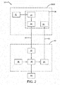
Figure 2 is a schematic representation of an exemplary embodiment of the mining vehicle monitoring and control system of the present invention; -
Figure 3 is a schematic representation of a display device of the system shown inFigure 2 ; and -
Figure 4 is a schematic representation of a mining site showing vehicles under conditions employing the system shown inFigure 2 . - Similar numerals refer to similar parts throughout the drawings.
- Turning to
Figure 1 , amining site 10 is represented schematically. Themining site 10 includes a pit orloading area 12, a hopper or unloading/dumping area 14 and amine road 16 extending between the pit and the hopper. Themine road 16 typically includes several curves or turns 18 andstraight areas 20.Multiple mining vehicles 22 transport raw material from thepit 12 to thehopper 14 along theroad 16. In the prior art, it has been common for thevehicles 22 to line up and wait to be loaded at thepit 12 and to line up and wait to dump at thehopper 14. Because of such waiting, the vehicle drivers often drive eachvehicle 22 rapidly along theroad 16, which undesirably increases fuel cost and tire wear. - Turning now to
Figure 2 , an exemplary embodiment of a mining vehicle monitoring and control system of the present invention is indicated generally at 30. The monitoring andcontrol system 30 includessensors 34 that preferably are located in a cab 26 of thevehicle 22.Exemplary sensors 34 include global positioning system (GPS) units, fuel consumption sensors, speed indicators, and other sensors that measure vehicle operating conditions. Thesensors 34 collect real-time data on the conditions 32 of thevehicle 22. - For example, the conditions 32 may include the location of the
vehicle 22 along the road 16 (Figure 1 ), the speed of the vehicle, the acceleration of the vehicle and the fuel level of the vehicle. Thesensors 34 collect the selected vehicle conditions 32 and the conditions are sent to an in-vehicle processor 38. Thesensors 34 and the in-vehicle processor 38 are integrated into an in-vehicle module 36 of the monitoring andcontrol system 30. Thesensors 34 are electronically connected to the in-vehicle processor 38, thereby enabling the collected data to be sent from the sensors to the processor. - The in-
vehicle processor 38 then transmits the collected data to a server 42 by wireless electronic transmission means 40, such as infrared transmission, radio waves and the like, including cellular data transmission. The server 42 includes data collection means 44, such as a hard drive or other data storage unit. The data collection means 44 is electronically connected to aprocessor 48 that executes a comparison between the actual vehicle conditions 32 and pre-loadedcontrol parameters 46. - The
pre-loaded control parameters 46 are determined in advance and are loaded onto the server. For example, thepre-loaded control parameters 46 may include a map of themine road 16, topology of the road and the surrounding area, the distance along the road, the number ofvehicles 22 operating at themining site 10, and the like. Theprocessor 48 determines optimized vehicle conditions based upon thecontrol parameters 46 to promote uniform vehicle spacing, fuel efficiency and reduced tire wear. Such optimized vehicle conditions include the ideal route along themine road 16 to be used and the optimum vehicle acceleration and speed at selected points along the mine road. - The
processor 48 compares the collected real-time vehicle condition data 32 to the optimized vehicle conditions and generates a set ofrecommendations 50. Therecommendations 50 include adjustments to specific real-time vehicle conditions that do not match the corresponding optimized vehicle conditions, as will be described below. If the real-time vehicle conditions match the corresponding optimized vehicle conditions, therecommendations 50 may include instructions to continue or hold the current conditions. Therecommendations 50 are transmitted to adisplay device 54 in the cab 26 of thevehicle 22 by wireless electronic transmission means 52, such as infrared transmission, radio waves and the like, including cellular data transmission. Preferably, thedisplay device 54 is incorporated into the in-vehicle module 36. The driver is able to see therecommendations 50 on thedisplay device 54 and adjust the vehicle operating conditions in real time to match the optimized conditions and thus reduce fuel consumption and tire wear. - Turning to
Figure 3 , a schematic representation of anexemplary display device 54 is shown. Thedisplay device 54 displays therecommendations 50 in a predetermined format that is configured based upon considerations for eachspecific mining site 10. For example, thedisplay device 54 may show recommended acceleration ordeceleration 56 for fuel efficiency and reduced tire wear, thelocation 58 ofother vehicles 22 so that optimum vehicle spacing may be maintained, a route map with anyroute issues 60, and other information orrecommendations 62. Specific aspects of the recommended acceleration ordeceleration 56, also referred to as driver scoring, thelocation 58 ofother vehicles 22 for optimum spacing, also referred to as a virtual bumper, and the route map with anyroute issues 60, also referred to as pothole detection, will be described in greater detail below. - When the driver sees the recommendations on the
display device 54, the driver can adjust his or her operation of thevehicle 22 according to the recommendations to optimize vehicle performance. For example, the driver may increase or decrease the vehicle speed, adjust the route of the vehicle, or adjust his or her frequency of vehicle braking. As shown inFigure 4 , such live feedback to the vehicle driver enables adjustment of the vehicle conditions to provide optimum spacing along themine road 16. Such uniform spacing reduces vehicle over-acceleration, which in turn reduces fuel consumption and tire wear. The monitoring and control system of theinvention 30 thus provides live feedback to drivers of the heavy-duty vehicles 22 to enable real-time control of vehicle conditions to optimize production time, reduce fuel cost and reduce tire wear. - Returning to
Figure 2 , in addition to theprocessor 48 immediately generatingrecommendations 50 for transmission to thedriver display device 54, the processor may store the comparison of the collected real-time data of the vehicle conditions 32 to the optimized vehicle conditions forlater analysis 64. With suchlater analysis 64, a manager of themining site 10 can evaluate the collected vehicle data 32 for each one of a group ofvehicles 22 to review driver performance, as well as to review and potentially adjust thecontrol parameters 46. The later analysis may enable further adjustments to the recommended vehicle operating conditions and thus provide additional optimization of production time, reduction of fuel cost and reduction of tire wear. - With reference to
Figures 2-4 , as mentioned above, the recommended acceleration ordeceleration 56 that is displayed to the vehicle driver is also referred to as driver scoring. As shown inFigure 4 , themine road 16 includescurves 18 andstraight sections 20. These aspects of themine road 16 are input into theprocessor 48 in advance ascontrol parameters 46. Theprocessor 48 then determines a vehicle speed and acceleration at eachspecific curve 18 andstraight section 20 that optimizes fuel consumption and tire wear, which are generated asrecommendations 50. The particular recommendations of vehicle acceleration ordeceleration 56 along each portion of themine road 16 are transmitted in real time to the vehicle driver and are displayed on thedisplay device 54. - For example, an optimum speed along a
straight section 20 may be about 28 miles per hour (1 mile per hour = 1.601 km per hour), and the driver may only be operating the vehicle at 19 miles per hour. Based upon the driver scoring 56, thedisplay device 54 will indicate that the driver should increase the vehicle speed from 19 miles per hour to 28 miles per hour. Likewise, an optimum speed on acurve 18 may be about 10 miles per hour, and the driver may be operating the vehicle at 18 miles per hour. Based upon the driver scoring 56, thedisplay device 54 will indicate that the driver should decrease the vehicle speed from 18 miles per hour to 10 miles per hour. - The driver scoring 56 for vehicle acceleration and deceleration can also be stored for
later analysis 64. For example, the actual vehicle speed can be compared to the optimum vehicle speed as a benchmark at specific points along themine road 16. In a three-month trial of the driver scoring 56 of the monitoring andcontrol system 30, providing vehicle drivers a comparison of the actual vehicle speed to optimum benchmark speeds yielded a reduction of fuel consumption of about eight percent (8%) and an improvement of tire life of about fifteen percent (15%). - The
location 58 ofother vehicles 22 for optimum spacing that is displayed to the vehicle driver is also referred to as a virtual bumper. As described above, in the prior art (Figure 1 ), thevehicles 22 may cluster together in certain areas along themine road 16, which results in an undesirable queue that reduces production time and leads to subsequent over-acceleration which increases fuel consumption and tire wear. In order to reduce such queuing, thevirtual bumper 58 provides instructions to the driver that enables optimum spacing between the vehicles to be maintained, as shown inFigure 4 . - More particularly, the location of each
vehicle 22 along themine road 16 is one of the collected vehicle conditions 32 of the monitoring andcontrol system 30. Based upon the distance of themine road 16 and the number ofvehicles 22, which are input ascontrol parameters 46, theprocessor 48 calculates optimum vehicle spacing, which is generated as arecommendation 50. The particular recommendation of the location of aspecific vehicle 22 relative to other vehicles is transmitted in real time to the vehicle driver and displayed on thedisplay device 54 as thevirtual bumper 58. Such real-time information to a driver of the location of his or hervehicle 22 relative to other vehicles in thevirtual bumper 58 enables the drivers to maintain optimum spacing between the vehicles, which reduces queuing and idling time. Such a reduction of queuing and idling time reduces subsequent over-acceleration, thereby reducing fuel consumption and tire wear. - The display of a route map with any
issues 60 is also referred to as pothole detection. In amining site 10, large equipment and raw materials are being moved, resulting in obstacles often appearing along themine road 16. In addition, themine road 16 is typically formed of earth and/or gravel, which enables large potholes to form from the traffic along the road. Frequent repair and/or regrading of themine road 16 is costly, so it is often more economical to route the vehicles around the hazards of obstacles and potholes rather than constantly repair the road. - To this end, one of the
control parameters 46 that is input intoprocessor 48 is the location of hazards, such as an obstacle or pothole, along themine road 16. Theprocessor 48 adjusts the routing of thevehicles 22 based upon the hazard location and generates an alert or routing adjustment as arecommendation 50. The particular recommendation of the location of the hazard and the re-routing instructions are transmitted in real time to the vehicle driver and displayed on thedisplay device 54 as thepothole detection 60. Such real-time information to a driver of the location of a hazard and rerouting instructions in thepothole detection 60 enables the drivers to avoid hazards. By avoiding such hazards, the performance of the tires and/or vehicle suspension is maintained without the expense of constant repair of themine road 16. In addition, by avoiding such hazards, tire wear is desirably reduced. - Another aspect of the monitoring and
control system 30 of the present invention is an optional speed limiting feature. For amining vehicle 22, it may be physically difficult for a driver to maintain a consistent vehicle speed for a long period of time, even though such a consistent speed may provide optimum performance. In order to assist the driver, the monitoring andcontrol system 30 may include a speed limiting device, such as an electronic throttle control, which responds to thevehicle speed recommendations 56. Alternatively, the speed limiting device may be a mechanical throttle control that is employed when a consistent speed is recommended by thedisplay device 54 for a relatively long period of time. For example, the mechanical speed limiting device may include a foot rest adjacent the throttle or pedal that is at the same elevation as the desired position of the throttle to achieve the recommended speed, which provides a physical benchmark for the driver and enables relief of pressure on the driver's leg. The mechanical speed limiting device may alternatively include an adjustment screw below the throttle or pedal that provides a positive stop which limits the travel of the throttle. - In this manner, the mining vehicle monitoring and
control system 30 of the present invention enables the driver of themining vehicle 22 to optimize the mining vehicle operating conditions based on real-time information to desirably optimize production time, reduce fuel cost and reduce tire wear. In addition, thesystem 30 provides forlater analysis 64 to enable further adjustments to the operating conditions of thevehicle 22 and provide additional optimization of production time, reduction of fuel cost and reduction of tire wear. - The present invention also includes a method of monitoring a mining vehicle and a method of controlling a mining vehicle. Each method includes steps in accordance with the description that is presented above and shown in
FIGS. 2-4 . - It is to be understood that the structure of the above-described mining vehicle monitoring and control system may be altered or rearranged, or components or steps known to those skilled in the art omitted or added, without affecting the overall concept or operation of the invention.
Claims (15)
- A mining vehicle monitoring and control system, the system (30) comprising:at least one sensor (34) being located in the vehicle, wherein the at least one sensor (34) is configured to collect real-time data for at least one condition (32) of the vehicle (22);a server (42) being located remote from the vehicle (22) and being configured to load at least one control parameter (46) onto the server (42);a first transmission means (40) for transmitting collected data to the server (42);a comparison means (48) in the server (42) for comparing the collected data to the at least one control parameter and for generating at least one vehicle condition recommendation (50) based upon the comparison;a display device (54) being located in the vehicle (22) in such a way that it is visible to a driver of the vehicle (2); anda second transmission means (52) for transmitting the at least one vehicle condition recommendation (50) from the server (42) to the display device (54).
- The mining vehicle monitoring and control system of claim 1, wherein the at least one sensor (34) includes at least one of a global positioning system unit, a fuel consumption sensor and a speed indicator.
- The mining vehicle monitoring and control system of claim 1 or 2, wherein the at least one condition (32) of the vehicle (20) includes at least one of a location of the vehicle, a speed of the vehicle, an acceleration of the vehicle and a fuel level of the vehicle.
- The mining vehicle monitoring and control system of at least one of the previous claims, wherein the first transmission means (40) and the second transmission means (52) each include wireless electronic transmission.
- The mining vehicle monitoring and control system of at least one of the previous claims, wherein the comparison means (48) includes an electronic processor that is configured to execute a comparison between the collected data and the at least one control parameter.
- The mining vehicle monitoring and control system of at least one of the previous claims, wherein the at least one control parameter includes at least one of a map of a mine road, a topology of a mine road, a distance along a mine road and a number of vehicles operating at a mining site.
- The mining vehicle monitoring and control system of at least one of the previous claims, wherein the server (42) is configured to store the collected data and the at least one control parameter for later analysis.
- The mining vehicle monitoring and control system of at least one of the previous claims, wherein the at least one vehicle condition recommendation (50) includes at least one of a recommended vehicle acceleration, recommended vehicle deceleration, a location of other vehicles and a route map, the at least one of a recommended vehicle acceleration and a recommended vehicle deceleration preferably corresponding to selected features of a mine road.
- The mining vehicle monitoring and control system of at least one of the previous claims, wherein the route map includes at least one of a display of a location of a hazard and re-routing instructions and/or wherein the system comprises a speed limiting feature or device.
- A method for controlling a mining vehicle, the method comprising the steps of:collecting real-time data for at least one condition (32) of a vehicle (22) with at least one sensor (34) disposed in the vehicle (22);transmitting the collected data to a server (42) that is remote from the vehicle (22);loading at least one control parameter (46) onto the server (42);comparing the at least one control parameter to the collected data;generating at least one vehicle condition recommendation (50) based on the comparison;transmitting the at least one vehicle condition recommendation (50) to a display device (54) disposed in the vehicle (22); anddisplaying the at least one vehicle condition recommendation (50) for a driver of the vehicle (22) on the display device (54).
- The method for controlling a mining vehicle of claim 10, wherein the step of collecting real-time data includes disposing at least one of a global positioning system unit, a fuel consumption sensor and a speed indicator in the vehicle; and/or wherein the step of collecting real-time data includes collecting at least one of a location of the vehicle, a speed of the vehicle, an acceleration of the vehicle and a fuel level of the vehicle.
- The method for controlling a mining vehicle of claim 10 or 11, wherein the step of transmitting the collected data to the server (42) and the step of transmitting the at least one vehicle condition recommendation (50) to the display device (54) each include wireless electronic transmission.
- The method for controlling a mining vehicle of at least one of the claims 10 to 12, wherein the step of comparing the at least one control parameter (46) to the collected data includes a control parameter comprising at least one of a map of a mine road, a topology of a mine road, a distance along a mine road and a number of vehicles operating at a mining site.
- The method for controlling a mining vehicle of at least one of the claims 10 to 13, further comprising the step of storing the collected data and the at least one control parameter for later analysis.
- The method for controlling a mining vehicle of at least one of the claims 10 to 14, wherein the step of generating at least one vehicle condition recommendation includes at least one of a recommended vehicle acceleration, recommended vehicle deceleration, a location of other vehicles and a route map; and/or wherein the location of other vehicles (22) includes optimum spacing to reduce a vehicle queuing time.
Applications Claiming Priority (1)
| Application Number | Priority Date | Filing Date | Title |
|---|---|---|---|
| US201662396271P | 2016-09-19 | 2016-09-19 |
Publications (2)
| Publication Number | Publication Date |
|---|---|
| EP3296128A1 true EP3296128A1 (en) | 2018-03-21 |
| EP3296128B1 EP3296128B1 (en) | 2020-12-09 |
Family
ID=59858974
Family Applications (1)
| Application Number | Title | Priority Date | Filing Date |
|---|---|---|---|
| EP17191068.0A Active EP3296128B1 (en) | 2016-09-19 | 2017-09-14 | Mining vehicle monitoring and control system |
Country Status (8)
| Country | Link |
|---|---|
| US (1) | US10672263B2 (en) |
| EP (1) | EP3296128B1 (en) |
| JP (1) | JP6934782B2 (en) |
| CN (1) | CN107839693B (en) |
| AU (1) | AU2017225005B2 (en) |
| CA (1) | CA2979454C (en) |
| CL (1) | CL2017002324A1 (en) |
| ES (1) | ES2848542T3 (en) |
Families Citing this family (13)
| Publication number | Priority date | Publication date | Assignee | Title |
|---|---|---|---|---|
| DE102017219585A1 (en) * | 2017-11-03 | 2019-05-09 | Zf Friedrichshafen Ag | Method for adjusting a comfort of a vehicle, control device and vehicle |
| JP7271109B2 (en) * | 2018-08-13 | 2023-05-11 | Toyo Tire株式会社 | Tire maintenance management device and tire maintenance system |
| WO2020065666A1 (en) * | 2018-09-26 | 2020-04-02 | Satish Mahadeo Burange | Real-time fuel consumption monitoring system |
| US20210004911A1 (en) * | 2019-07-05 | 2021-01-07 | Modifi, Inc. | Sensor-based monitoring system |
| US11150645B2 (en) * | 2019-07-22 | 2021-10-19 | Caterpillar Inc. | Localization system for underground mining applications |
| JP7349947B2 (en) * | 2020-03-26 | 2023-09-25 | 住友重機械工業株式会社 | Information processing equipment, working machines, information processing methods, information processing programs |
| CN115698636A (en) * | 2020-04-23 | 2023-02-03 | 动态清晰公司 | Terrain-based vehicle navigation and control |
| CN113763736A (en) * | 2021-07-23 | 2021-12-07 | 北京佰才邦技术股份有限公司 | Traffic information distribution method and system and electronic equipment |
| CN113866167B (en) * | 2021-09-13 | 2024-12-31 | 北京逸驰科技有限公司 | A method for generating tire detection results, computer equipment and storage medium |
| CN113931631A (en) * | 2021-09-15 | 2022-01-14 | 江苏徐工工程机械研究院有限公司 | Mining area manned auxiliary vehicle operation system and device thereof |
| CN114347903A (en) * | 2021-12-30 | 2022-04-15 | 中交二公局第六工程有限公司 | Prefabricated integrated pipe gallery transportation bump warning system |
| JPWO2024247320A1 (en) * | 2023-05-30 | 2024-12-05 | ||
| CN119063847B (en) * | 2024-08-27 | 2025-04-18 | 西藏高原大气环境科学研究所 | A method and device for remote sensing monitoring of surface temperature in complex plateau terrain |
Citations (5)
| Publication number | Priority date | Publication date | Assignee | Title |
|---|---|---|---|---|
| EP2703194A1 (en) * | 2012-09-03 | 2014-03-05 | Bridgestone Corporation | System for predicting tire casing life |
| US20150032373A1 (en) * | 2012-02-14 | 2015-01-29 | Hitachi Construction Machinery Co., Ltd. | Road surface management system |
| US20160155277A1 (en) * | 2014-11-27 | 2016-06-02 | Komatsu Ltd. | System for managing mining machinery, method for managing mining machinery, and dump truck |
| US20160167446A1 (en) * | 2014-12-10 | 2016-06-16 | The Goodyear Tire & Rubber Company | Tire service life monitoring |
| US20160258118A1 (en) * | 2014-03-19 | 2016-09-08 | Komatsu Ltd. | Road Surface Condition Determining Method, Road Surface Condition Outputting Method, Road Surface Condition Determining Device and Road Surface Condition Output Equipment |
Family Cites Families (16)
| Publication number | Priority date | Publication date | Assignee | Title |
|---|---|---|---|---|
| US4407388A (en) | 1980-03-19 | 1983-10-04 | Ogden Electronics, Ltd. | Collision prevention system |
| AUPQ181699A0 (en) | 1999-07-23 | 1999-08-19 | Cmte Development Limited | A system for relative vehicle navigation |
| US6633800B1 (en) | 2001-01-31 | 2003-10-14 | Ainsworth Inc. | Remote control system |
| FI115414B (en) | 2003-07-03 | 2005-04-29 | Sandvik Tamrock Oy | Arrangement for monitoring the location of the mining vehicle in the mine |
| JP5276778B2 (en) | 2005-08-31 | 2013-08-28 | 株式会社ブリヂストン | Tire information management system |
| FI120191B (en) | 2005-10-03 | 2009-07-31 | Sandvik Tamrock Oy | A method for driving mining vehicles in a mine and a transportation system |
| US7899584B2 (en) | 2007-02-28 | 2011-03-01 | Caterpillar Inc. | Method of controlling a vehicle based on operation characteristics |
| FI122157B (en) | 2010-05-10 | 2011-09-15 | Sandvik Mining & Constr Oy | Methods and apparatus for safety devices of mining vehicles |
| JP5596661B2 (en) * | 2011-11-11 | 2014-09-24 | 株式会社小松製作所 | Mining machine management system and mining machine management system management method |
| SE537371C2 (en) | 2011-11-18 | 2015-04-14 | Atlas Copco Rock Drills Ab | Method and apparatus for operating a mining and / or construction machine |
| JP5916444B2 (en) | 2012-03-08 | 2016-05-11 | 日立建機株式会社 | Mining vehicle |
| JP5890008B2 (en) * | 2012-04-12 | 2016-03-22 | 日立建機株式会社 | Mobile operation management system |
| CA2890338C (en) | 2012-11-07 | 2021-05-04 | Minetec Pty Ltd | A proximity awareness safety device and system |
| US8847788B2 (en) | 2012-11-15 | 2014-09-30 | Caterpillar Inc. | Traffic management |
| US9046371B2 (en) | 2013-03-29 | 2015-06-02 | Modular Mining Systems, Inc. | Contention avoidance |
| WO2016117713A1 (en) * | 2016-02-29 | 2016-07-28 | 株式会社小松製作所 | Control system for work machine, work machine, and management system for work machine |
-
2017
- 2017-09-05 AU AU2017225005A patent/AU2017225005B2/en not_active Ceased
- 2017-09-06 JP JP2017170946A patent/JP6934782B2/en active Active
- 2017-09-14 EP EP17191068.0A patent/EP3296128B1/en active Active
- 2017-09-14 CL CL2017002324A patent/CL2017002324A1/en unknown
- 2017-09-14 ES ES17191068T patent/ES2848542T3/en active Active
- 2017-09-18 CA CA2979454A patent/CA2979454C/en active Active
- 2017-09-18 US US15/707,251 patent/US10672263B2/en active Active
- 2017-09-19 CN CN201710846471.8A patent/CN107839693B/en active Active
Patent Citations (5)
| Publication number | Priority date | Publication date | Assignee | Title |
|---|---|---|---|---|
| US20150032373A1 (en) * | 2012-02-14 | 2015-01-29 | Hitachi Construction Machinery Co., Ltd. | Road surface management system |
| EP2703194A1 (en) * | 2012-09-03 | 2014-03-05 | Bridgestone Corporation | System for predicting tire casing life |
| US20160258118A1 (en) * | 2014-03-19 | 2016-09-08 | Komatsu Ltd. | Road Surface Condition Determining Method, Road Surface Condition Outputting Method, Road Surface Condition Determining Device and Road Surface Condition Output Equipment |
| US20160155277A1 (en) * | 2014-11-27 | 2016-06-02 | Komatsu Ltd. | System for managing mining machinery, method for managing mining machinery, and dump truck |
| US20160167446A1 (en) * | 2014-12-10 | 2016-06-16 | The Goodyear Tire & Rubber Company | Tire service life monitoring |
Also Published As
| Publication number | Publication date |
|---|---|
| JP6934782B2 (en) | 2021-09-15 |
| JP2018048545A (en) | 2018-03-29 |
| CN107839693A (en) | 2018-03-27 |
| US10672263B2 (en) | 2020-06-02 |
| AU2017225005A1 (en) | 2018-04-05 |
| BR102017019932A2 (en) | 2018-05-02 |
| CL2017002324A1 (en) | 2018-05-18 |
| US20180082579A1 (en) | 2018-03-22 |
| AU2017225005B2 (en) | 2021-07-08 |
| EP3296128B1 (en) | 2020-12-09 |
| ES2848542T3 (en) | 2021-08-10 |
| CN107839693B (en) | 2020-11-03 |
| CA2979454C (en) | 2025-12-23 |
| CA2979454A1 (en) | 2018-03-19 |
Similar Documents
| Publication | Publication Date | Title |
|---|---|---|
| EP3296128B1 (en) | Mining vehicle monitoring and control system | |
| US9734641B2 (en) | Driving analyzer and driving analyzing method for haulage vehicles | |
| AU2013400807B2 (en) | Tire abnormality management system, and tire abnormality management method | |
| US20160019792A1 (en) | Fleet Operation Management System | |
| US10424129B2 (en) | Tire condition telematics system | |
| AU2021206843B2 (en) | Methods and systems for determining and controlling vehicle speed | |
| US20150322873A1 (en) | Fuel-saving self-adjusting system for a vehicle engine | |
| US11780450B2 (en) | Tire management system and tire management method | |
| US8612066B2 (en) | Control system for payload limiting of hauling operation | |
| US6996464B2 (en) | Automated speed limiting based on machine located | |
| WO2020246319A1 (en) | Work field managing system and work field managing method | |
| US11797015B2 (en) | Method and system for determining a target vehicle speed of a vehicle operating at a worksite | |
| JP4911688B2 (en) | Vehicle control system | |
| CN111479742A (en) | Method and control device for controlling operation of a vehicle comprising axle load control of at least one vehicle during operation of the vehicle | |
| US20250001990A1 (en) | Method and control arrangement for controlling a brake system in a vehicle | |
| JP2022002001A (en) | Control system of unmanned vehicle, unmanned vehicle, and control method of unmanned vehicle | |
| BR102017019932B1 (en) | MINING VEHICLE CONTROL AND MONITORING SYSTEM AND METHOD FOR CONTROLLING A MINING VEHICLE |
Legal Events
| Date | Code | Title | Description |
|---|---|---|---|
| PUAI | Public reference made under article 153(3) epc to a published international application that has entered the european phase |
Free format text: ORIGINAL CODE: 0009012 |
|
| STAA | Information on the status of an ep patent application or granted ep patent |
Free format text: STATUS: THE APPLICATION HAS BEEN PUBLISHED |
|
| AK | Designated contracting states |
Kind code of ref document: A1 Designated state(s): AL AT BE BG CH CY CZ DE DK EE ES FI FR GB GR HR HU IE IS IT LI LT LU LV MC MK MT NL NO PL PT RO RS SE SI SK SM TR |
|
| AX | Request for extension of the european patent |
Extension state: BA ME |
|
| RIN1 | Information on inventor provided before grant (corrected) |
Inventor name: PRABHU, KRITHIKA Inventor name: MATSON, ERIC DENNIS Inventor name: JUNEJA, AMIT Inventor name: CAUTION, STEPHAN Inventor name: MAMIDISETTY, KRANTHI KUMAR |
|
| STAA | Information on the status of an ep patent application or granted ep patent |
Free format text: STATUS: REQUEST FOR EXAMINATION WAS MADE |
|
| 17P | Request for examination filed |
Effective date: 20180921 |
|
| RBV | Designated contracting states (corrected) |
Designated state(s): AL AT BE BG CH CY CZ DE DK EE ES FI FR GB GR HR HU IE IS IT LI LT LU LV MC MK MT NL NO PL PT RO RS SE SI SK SM TR |
|
| STAA | Information on the status of an ep patent application or granted ep patent |
Free format text: STATUS: EXAMINATION IS IN PROGRESS |
|
| 17Q | First examination report despatched |
Effective date: 20190111 |
|
| GRAP | Despatch of communication of intention to grant a patent |
Free format text: ORIGINAL CODE: EPIDOSNIGR1 |
|
| STAA | Information on the status of an ep patent application or granted ep patent |
Free format text: STATUS: GRANT OF PATENT IS INTENDED |
|
| INTG | Intention to grant announced |
Effective date: 20200630 |
|
| GRAS | Grant fee paid |
Free format text: ORIGINAL CODE: EPIDOSNIGR3 |
|
| GRAA | (expected) grant |
Free format text: ORIGINAL CODE: 0009210 |
|
| STAA | Information on the status of an ep patent application or granted ep patent |
Free format text: STATUS: THE PATENT HAS BEEN GRANTED |
|
| AK | Designated contracting states |
Kind code of ref document: B1 Designated state(s): AL AT BE BG CH CY CZ DE DK EE ES FI FR GB GR HR HU IE IS IT LI LT LU LV MC MK MT NL NO PL PT RO RS SE SI SK SM TR |
|
| REG | Reference to a national code |
Ref country code: GB Ref legal event code: FG4D |
|
| REG | Reference to a national code |
Ref country code: AT Ref legal event code: REF Ref document number: 1343051 Country of ref document: AT Kind code of ref document: T Effective date: 20201215 Ref country code: CH Ref legal event code: EP |
|
| REG | Reference to a national code |
Ref country code: DE Ref legal event code: R096 Ref document number: 602017029142 Country of ref document: DE |
|
| REG | Reference to a national code |
Ref country code: IE Ref legal event code: FG4D |
|
| PG25 | Lapsed in a contracting state [announced via postgrant information from national office to epo] |
Ref country code: FI Free format text: LAPSE BECAUSE OF FAILURE TO SUBMIT A TRANSLATION OF THE DESCRIPTION OR TO PAY THE FEE WITHIN THE PRESCRIBED TIME-LIMIT Effective date: 20201209 Ref country code: GR Free format text: LAPSE BECAUSE OF FAILURE TO SUBMIT A TRANSLATION OF THE DESCRIPTION OR TO PAY THE FEE WITHIN THE PRESCRIBED TIME-LIMIT Effective date: 20210310 Ref country code: RS Free format text: LAPSE BECAUSE OF FAILURE TO SUBMIT A TRANSLATION OF THE DESCRIPTION OR TO PAY THE FEE WITHIN THE PRESCRIBED TIME-LIMIT Effective date: 20201209 Ref country code: NO Free format text: LAPSE BECAUSE OF FAILURE TO SUBMIT A TRANSLATION OF THE DESCRIPTION OR TO PAY THE FEE WITHIN THE PRESCRIBED TIME-LIMIT Effective date: 20210309 |
|
| REG | Reference to a national code |
Ref country code: AT Ref legal event code: MK05 Ref document number: 1343051 Country of ref document: AT Kind code of ref document: T Effective date: 20201209 |
|
| PG25 | Lapsed in a contracting state [announced via postgrant information from national office to epo] |
Ref country code: SE Free format text: LAPSE BECAUSE OF FAILURE TO SUBMIT A TRANSLATION OF THE DESCRIPTION OR TO PAY THE FEE WITHIN THE PRESCRIBED TIME-LIMIT Effective date: 20201209 Ref country code: LV Free format text: LAPSE BECAUSE OF FAILURE TO SUBMIT A TRANSLATION OF THE DESCRIPTION OR TO PAY THE FEE WITHIN THE PRESCRIBED TIME-LIMIT Effective date: 20201209 Ref country code: BG Free format text: LAPSE BECAUSE OF FAILURE TO SUBMIT A TRANSLATION OF THE DESCRIPTION OR TO PAY THE FEE WITHIN THE PRESCRIBED TIME-LIMIT Effective date: 20210309 |
|
| REG | Reference to a national code |
Ref country code: NL Ref legal event code: MP Effective date: 20201209 |
|
| PG25 | Lapsed in a contracting state [announced via postgrant information from national office to epo] |
Ref country code: HR Free format text: LAPSE BECAUSE OF FAILURE TO SUBMIT A TRANSLATION OF THE DESCRIPTION OR TO PAY THE FEE WITHIN THE PRESCRIBED TIME-LIMIT Effective date: 20201209 Ref country code: NL Free format text: LAPSE BECAUSE OF FAILURE TO SUBMIT A TRANSLATION OF THE DESCRIPTION OR TO PAY THE FEE WITHIN THE PRESCRIBED TIME-LIMIT Effective date: 20201209 |
|
| REG | Reference to a national code |
Ref country code: LT Ref legal event code: MG9D |
|
| PG25 | Lapsed in a contracting state [announced via postgrant information from national office to epo] |
Ref country code: SK Free format text: LAPSE BECAUSE OF FAILURE TO SUBMIT A TRANSLATION OF THE DESCRIPTION OR TO PAY THE FEE WITHIN THE PRESCRIBED TIME-LIMIT Effective date: 20201209 Ref country code: PT Free format text: LAPSE BECAUSE OF FAILURE TO SUBMIT A TRANSLATION OF THE DESCRIPTION OR TO PAY THE FEE WITHIN THE PRESCRIBED TIME-LIMIT Effective date: 20210409 Ref country code: RO Free format text: LAPSE BECAUSE OF FAILURE TO SUBMIT A TRANSLATION OF THE DESCRIPTION OR TO PAY THE FEE WITHIN THE PRESCRIBED TIME-LIMIT Effective date: 20201209 Ref country code: CZ Free format text: LAPSE BECAUSE OF FAILURE TO SUBMIT A TRANSLATION OF THE DESCRIPTION OR TO PAY THE FEE WITHIN THE PRESCRIBED TIME-LIMIT Effective date: 20201209 Ref country code: EE Free format text: LAPSE BECAUSE OF FAILURE TO SUBMIT A TRANSLATION OF THE DESCRIPTION OR TO PAY THE FEE WITHIN THE PRESCRIBED TIME-LIMIT Effective date: 20201209 Ref country code: SM Free format text: LAPSE BECAUSE OF FAILURE TO SUBMIT A TRANSLATION OF THE DESCRIPTION OR TO PAY THE FEE WITHIN THE PRESCRIBED TIME-LIMIT Effective date: 20201209 Ref country code: LT Free format text: LAPSE BECAUSE OF FAILURE TO SUBMIT A TRANSLATION OF THE DESCRIPTION OR TO PAY THE FEE WITHIN THE PRESCRIBED TIME-LIMIT Effective date: 20201209 |
|
| REG | Reference to a national code |
Ref country code: ES Ref legal event code: FG2A Ref document number: 2848542 Country of ref document: ES Kind code of ref document: T3 Effective date: 20210810 |
|
| PG25 | Lapsed in a contracting state [announced via postgrant information from national office to epo] |
Ref country code: PL Free format text: LAPSE BECAUSE OF FAILURE TO SUBMIT A TRANSLATION OF THE DESCRIPTION OR TO PAY THE FEE WITHIN THE PRESCRIBED TIME-LIMIT Effective date: 20201209 Ref country code: AT Free format text: LAPSE BECAUSE OF FAILURE TO SUBMIT A TRANSLATION OF THE DESCRIPTION OR TO PAY THE FEE WITHIN THE PRESCRIBED TIME-LIMIT Effective date: 20201209 |
|
| REG | Reference to a national code |
Ref country code: DE Ref legal event code: R097 Ref document number: 602017029142 Country of ref document: DE |
|
| PG25 | Lapsed in a contracting state [announced via postgrant information from national office to epo] |
Ref country code: IS Free format text: LAPSE BECAUSE OF FAILURE TO SUBMIT A TRANSLATION OF THE DESCRIPTION OR TO PAY THE FEE WITHIN THE PRESCRIBED TIME-LIMIT Effective date: 20210409 |
|
| PLBE | No opposition filed within time limit |
Free format text: ORIGINAL CODE: 0009261 |
|
| STAA | Information on the status of an ep patent application or granted ep patent |
Free format text: STATUS: NO OPPOSITION FILED WITHIN TIME LIMIT |
|
| PG25 | Lapsed in a contracting state [announced via postgrant information from national office to epo] |
Ref country code: AL Free format text: LAPSE BECAUSE OF FAILURE TO SUBMIT A TRANSLATION OF THE DESCRIPTION OR TO PAY THE FEE WITHIN THE PRESCRIBED TIME-LIMIT Effective date: 20201209 |
|
| 26N | No opposition filed |
Effective date: 20210910 |
|
| PG25 | Lapsed in a contracting state [announced via postgrant information from national office to epo] |
Ref country code: DK Free format text: LAPSE BECAUSE OF FAILURE TO SUBMIT A TRANSLATION OF THE DESCRIPTION OR TO PAY THE FEE WITHIN THE PRESCRIBED TIME-LIMIT Effective date: 20201209 Ref country code: SI Free format text: LAPSE BECAUSE OF FAILURE TO SUBMIT A TRANSLATION OF THE DESCRIPTION OR TO PAY THE FEE WITHIN THE PRESCRIBED TIME-LIMIT Effective date: 20201209 |
|
| REG | Reference to a national code |
Ref country code: CH Ref legal event code: PL |
|
| REG | Reference to a national code |
Ref country code: BE Ref legal event code: MM Effective date: 20210930 |
|
| GBPC | Gb: european patent ceased through non-payment of renewal fee |
Effective date: 20210914 |
|
| PG25 | Lapsed in a contracting state [announced via postgrant information from national office to epo] |
Ref country code: IS Free format text: LAPSE BECAUSE OF FAILURE TO SUBMIT A TRANSLATION OF THE DESCRIPTION OR TO PAY THE FEE WITHIN THE PRESCRIBED TIME-LIMIT Effective date: 20210409 Ref country code: MC Free format text: LAPSE BECAUSE OF FAILURE TO SUBMIT A TRANSLATION OF THE DESCRIPTION OR TO PAY THE FEE WITHIN THE PRESCRIBED TIME-LIMIT Effective date: 20201209 |
|
| PG25 | Lapsed in a contracting state [announced via postgrant information from national office to epo] |
Ref country code: LU Free format text: LAPSE BECAUSE OF NON-PAYMENT OF DUE FEES Effective date: 20210914 Ref country code: IE Free format text: LAPSE BECAUSE OF NON-PAYMENT OF DUE FEES Effective date: 20210914 Ref country code: GB Free format text: LAPSE BECAUSE OF NON-PAYMENT OF DUE FEES Effective date: 20210914 Ref country code: BE Free format text: LAPSE BECAUSE OF NON-PAYMENT OF DUE FEES Effective date: 20210930 |
|
| PG25 | Lapsed in a contracting state [announced via postgrant information from national office to epo] |
Ref country code: LI Free format text: LAPSE BECAUSE OF NON-PAYMENT OF DUE FEES Effective date: 20210930 Ref country code: CH Free format text: LAPSE BECAUSE OF NON-PAYMENT OF DUE FEES Effective date: 20210930 |
|
| PG25 | Lapsed in a contracting state [announced via postgrant information from national office to epo] |
Ref country code: HU Free format text: LAPSE BECAUSE OF FAILURE TO SUBMIT A TRANSLATION OF THE DESCRIPTION OR TO PAY THE FEE WITHIN THE PRESCRIBED TIME-LIMIT; INVALID AB INITIO Effective date: 20170914 |
|
| PG25 | Lapsed in a contracting state [announced via postgrant information from national office to epo] |
Ref country code: CY Free format text: LAPSE BECAUSE OF FAILURE TO SUBMIT A TRANSLATION OF THE DESCRIPTION OR TO PAY THE FEE WITHIN THE PRESCRIBED TIME-LIMIT Effective date: 20201209 |
|
| PG25 | Lapsed in a contracting state [announced via postgrant information from national office to epo] |
Ref country code: MK Free format text: LAPSE BECAUSE OF FAILURE TO SUBMIT A TRANSLATION OF THE DESCRIPTION OR TO PAY THE FEE WITHIN THE PRESCRIBED TIME-LIMIT Effective date: 20201209 |
|
| PG25 | Lapsed in a contracting state [announced via postgrant information from national office to epo] |
Ref country code: MT Free format text: LAPSE BECAUSE OF FAILURE TO SUBMIT A TRANSLATION OF THE DESCRIPTION OR TO PAY THE FEE WITHIN THE PRESCRIBED TIME-LIMIT Effective date: 20201209 |
|
| PGFP | Annual fee paid to national office [announced via postgrant information from national office to epo] |
Ref country code: DE Payment date: 20240702 Year of fee payment: 8 |
|
| PGFP | Annual fee paid to national office [announced via postgrant information from national office to epo] |
Ref country code: FR Payment date: 20240702 Year of fee payment: 8 |
|
| PGFP | Annual fee paid to national office [announced via postgrant information from national office to epo] |
Ref country code: IT Payment date: 20240812 Year of fee payment: 8 |
|
| PGFP | Annual fee paid to national office [announced via postgrant information from national office to epo] |
Ref country code: ES Payment date: 20241009 Year of fee payment: 8 |
|
| PG25 | Lapsed in a contracting state [announced via postgrant information from national office to epo] |
Ref country code: TR Free format text: LAPSE BECAUSE OF FAILURE TO SUBMIT A TRANSLATION OF THE DESCRIPTION OR TO PAY THE FEE WITHIN THE PRESCRIBED TIME-LIMIT Effective date: 20201209 |