EP3296039A1 - A method of manufacturing a component from a nickel-based superalloy - Google Patents
A method of manufacturing a component from a nickel-based superalloy Download PDFInfo
- Publication number
- EP3296039A1 EP3296039A1 EP17187631.1A EP17187631A EP3296039A1 EP 3296039 A1 EP3296039 A1 EP 3296039A1 EP 17187631 A EP17187631 A EP 17187631A EP 3296039 A1 EP3296039 A1 EP 3296039A1
- Authority
- EP
- European Patent Office
- Prior art keywords
- component
- component blank
- blank
- casting
- superalloy
- Prior art date
- Legal status (The legal status is an assumption and is not a legal conclusion. Google has not performed a legal analysis and makes no representation as to the accuracy of the status listed.)
- Withdrawn
Links
Images



Classifications
-
- C—CHEMISTRY; METALLURGY
- C22—METALLURGY; FERROUS OR NON-FERROUS ALLOYS; TREATMENT OF ALLOYS OR NON-FERROUS METALS
- C22F—CHANGING THE PHYSICAL STRUCTURE OF NON-FERROUS METALS AND NON-FERROUS ALLOYS
- C22F1/00—Changing the physical structure of non-ferrous metals or alloys by heat treatment or by hot or cold working
- C22F1/10—Changing the physical structure of non-ferrous metals or alloys by heat treatment or by hot or cold working of nickel or cobalt or alloys based thereon
-
- B—PERFORMING OPERATIONS; TRANSPORTING
- B22—CASTING; POWDER METALLURGY
- B22D—CASTING OF METALS; CASTING OF OTHER SUBSTANCES BY THE SAME PROCESSES OR DEVICES
- B22D27/00—Treating the metal in the mould while it is molten or ductile ; Pressure or vacuum casting
- B22D27/04—Influencing the temperature of the metal, e.g. by heating or cooling the mould
- B22D27/045—Directionally solidified castings
-
- B—PERFORMING OPERATIONS; TRANSPORTING
- B24—GRINDING; POLISHING
- B24C—ABRASIVE OR RELATED BLASTING WITH PARTICULATE MATERIAL
- B24C1/00—Methods for use of abrasive blasting for producing particular effects; Use of auxiliary equipment in connection with such methods
- B24C1/10—Methods for use of abrasive blasting for producing particular effects; Use of auxiliary equipment in connection with such methods for compacting surfaces, e.g. shot-peening
-
- F—MECHANICAL ENGINEERING; LIGHTING; HEATING; WEAPONS; BLASTING
- F01—MACHINES OR ENGINES IN GENERAL; ENGINE PLANTS IN GENERAL; STEAM ENGINES
- F01D—NON-POSITIVE DISPLACEMENT MACHINES OR ENGINES, e.g. STEAM TURBINES
- F01D5/00—Blades; Blade-carrying members; Heating, heat-insulating, cooling or antivibration means on the blades or the members
- F01D5/12—Blades
- F01D5/28—Selecting particular materials; Particular measures relating thereto; Measures against erosion or corrosion
- F01D5/286—Particular treatment of blades, e.g. to increase durability or resistance against corrosion or erosion
-
- B—PERFORMING OPERATIONS; TRANSPORTING
- B24—GRINDING; POLISHING
- B24C—ABRASIVE OR RELATED BLASTING WITH PARTICULATE MATERIAL
- B24C1/00—Methods for use of abrasive blasting for producing particular effects; Use of auxiliary equipment in connection with such methods
- B24C1/08—Methods for use of abrasive blasting for producing particular effects; Use of auxiliary equipment in connection with such methods for polishing surfaces, e.g. smoothing a surface by making use of liquid-borne abrasives
-
- C—CHEMISTRY; METALLURGY
- C21—METALLURGY OF IRON
- C21D—MODIFYING THE PHYSICAL STRUCTURE OF FERROUS METALS; GENERAL DEVICES FOR HEAT TREATMENT OF FERROUS OR NON-FERROUS METALS OR ALLOYS; MAKING METAL MALLEABLE, e.g. BY DECARBURISATION OR TEMPERING
- C21D7/00—Modifying the physical properties of iron or steel by deformation
- C21D7/02—Modifying the physical properties of iron or steel by deformation by cold working
- C21D7/04—Modifying the physical properties of iron or steel by deformation by cold working of the surface
- C21D7/06—Modifying the physical properties of iron or steel by deformation by cold working of the surface by shot-peening or the like
-
- F—MECHANICAL ENGINEERING; LIGHTING; HEATING; WEAPONS; BLASTING
- F05—INDEXING SCHEMES RELATING TO ENGINES OR PUMPS IN VARIOUS SUBCLASSES OF CLASSES F01-F04
- F05D—INDEXING SCHEME FOR ASPECTS RELATING TO NON-POSITIVE-DISPLACEMENT MACHINES OR ENGINES, GAS-TURBINES OR JET-PROPULSION PLANTS
- F05D2230/00—Manufacture
- F05D2230/10—Manufacture by removing material
-
- F—MECHANICAL ENGINEERING; LIGHTING; HEATING; WEAPONS; BLASTING
- F05—INDEXING SCHEMES RELATING TO ENGINES OR PUMPS IN VARIOUS SUBCLASSES OF CLASSES F01-F04
- F05D—INDEXING SCHEME FOR ASPECTS RELATING TO NON-POSITIVE-DISPLACEMENT MACHINES OR ENGINES, GAS-TURBINES OR JET-PROPULSION PLANTS
- F05D2230/00—Manufacture
- F05D2230/20—Manufacture essentially without removing material
- F05D2230/21—Manufacture essentially without removing material by casting
- F05D2230/211—Manufacture essentially without removing material by casting by precision casting, e.g. microfusing or investment casting
-
- F—MECHANICAL ENGINEERING; LIGHTING; HEATING; WEAPONS; BLASTING
- F05—INDEXING SCHEMES RELATING TO ENGINES OR PUMPS IN VARIOUS SUBCLASSES OF CLASSES F01-F04
- F05D—INDEXING SCHEME FOR ASPECTS RELATING TO NON-POSITIVE-DISPLACEMENT MACHINES OR ENGINES, GAS-TURBINES OR JET-PROPULSION PLANTS
- F05D2230/00—Manufacture
- F05D2230/20—Manufacture essentially without removing material
- F05D2230/26—Manufacture essentially without removing material by rolling
-
- F—MECHANICAL ENGINEERING; LIGHTING; HEATING; WEAPONS; BLASTING
- F05—INDEXING SCHEMES RELATING TO ENGINES OR PUMPS IN VARIOUS SUBCLASSES OF CLASSES F01-F04
- F05D—INDEXING SCHEME FOR ASPECTS RELATING TO NON-POSITIVE-DISPLACEMENT MACHINES OR ENGINES, GAS-TURBINES OR JET-PROPULSION PLANTS
- F05D2230/00—Manufacture
- F05D2230/40—Heat treatment
- F05D2230/42—Heat treatment by hot isostatic pressing
-
- F—MECHANICAL ENGINEERING; LIGHTING; HEATING; WEAPONS; BLASTING
- F05—INDEXING SCHEMES RELATING TO ENGINES OR PUMPS IN VARIOUS SUBCLASSES OF CLASSES F01-F04
- F05D—INDEXING SCHEME FOR ASPECTS RELATING TO NON-POSITIVE-DISPLACEMENT MACHINES OR ENGINES, GAS-TURBINES OR JET-PROPULSION PLANTS
- F05D2250/00—Geometry
- F05D2250/60—Structure; Surface texture
- F05D2250/62—Structure; Surface texture smooth or fine
- F05D2250/621—Structure; Surface texture smooth or fine polished
-
- F—MECHANICAL ENGINEERING; LIGHTING; HEATING; WEAPONS; BLASTING
- F05—INDEXING SCHEMES RELATING TO ENGINES OR PUMPS IN VARIOUS SUBCLASSES OF CLASSES F01-F04
- F05D—INDEXING SCHEME FOR ASPECTS RELATING TO NON-POSITIVE-DISPLACEMENT MACHINES OR ENGINES, GAS-TURBINES OR JET-PROPULSION PLANTS
- F05D2250/00—Geometry
- F05D2250/60—Structure; Surface texture
- F05D2250/63—Structure; Surface texture coarse
Definitions
- the present disclosure relates to a method of manufacturing a metallic component from a nickel-based superalloy and particularly, but not exclusively, to a method of manufacturing a compressor blade for a gas turbine engine from a nickel-based superalloy.
- Figure 1 shows a partial cross-section of a turbofan gas turbine engine that comprises, in flow series, an intake 11, a fan 12, an intermediate pressure compressor 13, a high pressure compressor 14, a combustion chamber 15, a high pressure turbine 16, an intermediate pressure turbine 17, a low pressure turbine 18 and an exhaust 19.
- the high pressure turbine 16 is arranged to drive the high pressure compressor 14 via a first shaft 26.
- the intermediate pressure turbine 17 is arranged to drive the intermediate pressure compressor 13 via a second shaft 28 and the low pressure turbine 18 is arranged to drive the fan 12 via a third shaft 30.
- air flows into the intake 11 and is compressed by the fan 12.
- a first portion of the air flows through, and is compressed by, the intermediate pressure compressor 13 and the high pressure compressor 14 and is supplied to the combustion chamber 15.
- Fuel is injected into the combustion chamber 15 and is burnt in the air to produce hot exhaust gases which flow through, and drive, the high pressure turbine 16, the intermediate pressure turbine 17 and the low pressure turbine 18.
- the hot exhaust gases leaving the low pressure turbine 18 flow through the exhaust 19 to provide propulsive thrust.
- a second portion of the air bypasses the main engine to provide propulsive thrust.
- Some high temperature nickel-based superalloy materials cannot be forged because of their creep resistance. Examples include Inconel RTM 713, Inconel RTM 738, and CM247LC (produced by Cannon Muskegan)
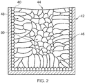
- FIG. 2 shows a schematic sectional view of a cast component.
- the component 40 has been cast into a mould 42.
- the exposed surface of the cast component shows some shrinkage 44.
- the surface in contact with the mould comprises a chill zone 46 in which the grain structure of the material is fine. Extending further into the cast component from this chill zone 46, the grain structure is initially columnar 48. Extending into the core of the cast component, the grain structure becomes equi-axed 50. This variation in grain structure is deleterious to the mechanical properties of the component.
- the grain structure is less uniform, because the grain structure is highly dependent on cooling rates and the direction of heat flux from the mould. This would require an additional grain refinement step in order to achieve a fine uniform grain structure.
- metal injection moulding could be used to produce compressor rotor blades from high temperature superalloys.
- a disadvantage of the metal injection moulded components is that the resulting material properties tend to be inferior to those of forged components. Furthermore, the cost of tooling and the powder material results in the metal injection moulding process being more expensive than casting.
- a method of manufacturing a component from a nickel-based superalloy comprising the steps of:
- the method of the disclosure utilises a casting technique to prepare a component blank that is subsequently subjected to a specific sequence of processing steps to thereby arrive at a finished component that can be operated at high temperatures with enhanced high cycle and low cycle fatigue properties.
- the use of a chill plate within the mould cavity facilitates rapid cooling of the cast component blank after its withdrawal from the furnace to maintain a single crystal structure within the component blank.
- the surface modification step improves the surface finish of the component blank whilst also producing a residual compressive stress in the surface layer of the component blank.
- this compressive stress will produce dislocations in the structure of the surface layer, which will act as nucleation sites for recrystallization during the subsequent heat treatment.
- the solution heat treatment and subsequent precipitation heat treatment will follow a standard process dependent upon the superalloy composition selected.
- the residual stresses produced by the peening and that produced by the surface modification step will result in further recrystallization and grain refinement of the superalloy structure.
- Performing the solution heat treatment at or above the y'-solvus temperature for the superalloy ensures the recrystallization and grain refinement of the superalloy structure.
- the solution heat treatment and the precipitation heat treatment cycles would be arranged so as to achieve an optimum grain size for the desired combination of creep and fatigue properties for the component.
- the step of peening the surface of the component blank comprises the subsequent step of:
- the hot isostatic pressing step will close any sub-surface pores in the cast component blank whilst allowing the recrystallization of the grain structure to begin.
- the step of casting a component blank comprises the step of:
- the step of peening the surface of the component blank comprises the further initial step of:
- the hot isostatic pressing step has a duration of approximately 60 minutes.
- Restricting the duration of the hot isostatic pressing step to approximately 60 minutes allows recrystallization to occur in the structure of the surface of the component blank, while ensuring that the recrystallized grains do not coarsen.
- the surface modification technique is a vibro-polishing process.
- Vibro-polishing is a process in which a component is immersed in a container together with shaped media, and then subjected to a vibratory action.
- the vibro-polishing process is a burnishing process.
- the vibro-polishing process is a burnishing process.
- the surface modification technique is a cold rolling process.
- the vibro-polishing process is a cold rolling process.
- the step of hot isostatic pressing the peened surface of the component blank comprises the further step of:
- the method further comprises the step of finish machining the component blank.
- the component blank will require some final machining after the completion of the heat treatment processes. This may take the form of any suitable process for use on heat treated components such as, for example, grinding.
- turbomachine component manufactured by a method according to the first aspect.
- turbomachine components are particularly suitable for manufacture by the method of the disclosure because of their need for a material having good high temperature properties and the inability of such materials to be forged.
- a compressor blade for a gas turbine engine wherein the compressor blade is manufactured by a method according to the first aspect.
- aspects of the disclosure provide devices, methods and systems which include and/or implement some or all of the actions described herein.
- the illustrative aspects of the disclosure are designed to solve one or more of the problems herein described and/or one or more other problems not discussed.
- FIG. 3 a method of manufacturing a component according to a first embodiment of the disclosure is designated generally by the reference numeral 100.
- Figure 5 illustrates an example furnace arrangement that could be used with the method of the present disclosure.
- the furnace 300 provided at step 110 is a vacuum casting furnace of a conventional nature. No further explanation of the structure and function of the furnace is provided as this would be understood by a skilled person.
- a mould assembly 310 is positioned on a chill plate 330 within the furnace 300.
- the mould assembly 310 is heated to a temperature of approximately 30°C or 40°C above the liquidus temperature of the superalloy being cast. In the present embodiment, this will be approximately 1430°C.
- the chill plate is a copper chill plate.
- the chill plate facilitates the rapid cooling of the case component blanks following their withdrawal from the furnace.
- the mould assembly 310 comprises a central sprue 312 from which extend a number of component moulds 313. Each of these component moulds 313 will house at least one rotor blade casting 320.
- a component blank in this case a turbine blade blank, is cast into the component mould 313.
- a restrictor 316 is provided between the central sprue 312 and each of the component moulds 313. This restrictor 316 acts to further prevent the directionally solidified grain structure of the solidifying sprue material from entering the blade cavity.
- each of the component blanks 320 is oriented perpendicularly to the chill plate.
- each of the component moulds 313 could extend radially outwardly from the central sprue 312.
- the components blanks 320 could be oriented perpendicularly to the central sprue 312.
- each of the component blanks 320 is fettled to remove extraneous sprue material.
- the component blank 320 is subjected to a peening process, for example by bead blasting. This induces a compressive stress layer immediately below the surface of the component blank 320.
- the peened component blank 320 is subjected to a hot isostatic pressing (HIP) operation for a period of approximately 1 hour.
- the compressive stress produced by the pressing operation acts to close any sub-surface pores in the component blank 320.
- the elevated temperature of the process allows some recrystallization to take place in the microstructure of the component blank 320.
- the duration of the HIP process is selected to allow only a pre-determined degree of recrystallization.
- the component blank 320 is subjected to a burnishing process to improve the surface finish of the component blank 320, whilst also producing a residual compressive stress in the component surface.
- the residual compressive stress resulting from the burnishing process promotes further recrystallization during subsequent heat treatment.
- Step 170 involves subjecting the component blank 320 to a standard solution heat treatment process.
- the solution heat treatment process will be selected in dependence on the composition of the metal alloy used for the component blank 320.
- the component blank is subjected to a standard precipitation heat treatment process.
- the parameters for the heat treatment process of step 180 will be selected on the basis of the composition of the metal superalloy used for the component blank 320.
- a method of manufacturing a component according to a second embodiment of the disclosure is designated generally by the reference numeral 200.
- Features of the method 200 which correspond to those of method 100 have been given corresponding reference numerals for ease of reference.
- the method 200 comprises all of the steps of the method 100 with the addition of three additional steps 236,256 and 290.
- Step 236 involves cleaning the surface of the component blank 320 prior to the burnishing operation of step 240.
- the blasting may be required where the surface of the component blank 320 is not sufficiently clean for the peening operation to uniformly induce the compressive stress layer in the surface of the component blank 320.
- step 256 some or all of the surface of the component blank 320 may be rough machined to bring the geometry of the component blank closer to, if to directly to, the required geometry of the finished component. This step may be advantageous because it will be easier to remove material from the surface of the component blank before the heat treatment processes than it will be after these have been carried out.
- Step 290 involves finish machining the component blank. Depending upon the complexity of the geometry of the finished component, it may not be necessary to further machine the surface of the component blank.
Landscapes
- Engineering & Computer Science (AREA)
- Chemical & Material Sciences (AREA)
- Mechanical Engineering (AREA)
- Materials Engineering (AREA)
- Physics & Mathematics (AREA)
- Thermal Sciences (AREA)
- Crystallography & Structural Chemistry (AREA)
- Metallurgy (AREA)
- Organic Chemistry (AREA)
- General Engineering & Computer Science (AREA)
- Turbine Rotor Nozzle Sealing (AREA)
Abstract
providing a vacuum induction casting furnace;
positioning a component mould onto a chill plate within the furnace;
casting a component blank;
peening the surface of the component blank;
applying a surface modification technique to the surface of the component blank;
solution heat treating the component blank at or above the γ'-solvus temperature for the superalloy; and
precipitation heat treating the component blank.
Description
- The present disclosure relates to a method of manufacturing a metallic component from a nickel-based superalloy and particularly, but not exclusively, to a method of manufacturing a compressor blade for a gas turbine engine from a nickel-based superalloy.
-
Figure 1 shows a partial cross-section of a turbofan gas turbine engine that comprises, in flow series, anintake 11, afan 12, an intermediate pressure compressor 13, ahigh pressure compressor 14, acombustion chamber 15, a high pressure turbine 16, an intermediate pressure turbine 17, alow pressure turbine 18 and anexhaust 19. The high pressure turbine 16 is arranged to drive thehigh pressure compressor 14 via afirst shaft 26. The intermediate pressure turbine 17 is arranged to drive the intermediate pressure compressor 13 via asecond shaft 28 and thelow pressure turbine 18 is arranged to drive thefan 12 via athird shaft 30. In operation air flows into theintake 11 and is compressed by thefan 12. A first portion of the air flows through, and is compressed by, the intermediate pressure compressor 13 and thehigh pressure compressor 14 and is supplied to thecombustion chamber 15. Fuel is injected into thecombustion chamber 15 and is burnt in the air to produce hot exhaust gases which flow through, and drive, the high pressure turbine 16, the intermediate pressure turbine 17 and thelow pressure turbine 18. The hot exhaust gases leaving thelow pressure turbine 18 flow through theexhaust 19 to provide propulsive thrust. A second portion of the air bypasses the main engine to provide propulsive thrust. - It is known to improve cycle efficiency of a gas turbine by increasing, for example, the high pressure spool rotational speed and the high pressure compressor exit temperature. Current developments are targeting temperatures of over 1000K at the exit from the high pressure compressor. This temperature is above the operating temperature of current metal alloy materials used for the high pressure compressor blades such as, for example, NimonicRTM N105.
- Some high temperature nickel-based superalloy materials cannot be forged because of their creep resistance. Examples include InconelRTM 713, InconelRTM 738, and CM247LC (produced by Cannon Muskegan)
- Conventional manufacturing techniques for compressor rotor blades involve the use of closed die forging followed by machining. The types of superalloys required to operate at in the above-mentioned high temperature environments cannot be forged due to their high temperature strengths and low ductility. For these reasons only casting or powder metallurgy processes such as metal injection moulding would be suitable.
- At normal forging temperatures, such materials have too high a yield stress to allow them to be forged. However, if the forging temperature is increased to the level at which forging could take place, there would be a risk of incipient melting of the superalloy material. In other words, at a temperature high enough to plastically deform the superalloy material, the temperature would be close to the start of the melting range for the superalloy.
- Investment casting could be used to produce compressor rotor blades in high temperature superalloys. A disadvantage of such a method is that the resulting grain structure is coarser than that obtainable from forging techniques.
Figure 2 shows a schematic sectional view of a cast component. Thecomponent 40 has been cast into amould 42. The exposed surface of the cast component shows someshrinkage 44. The surface in contact with the mould comprises achill zone 46 in which the grain structure of the material is fine. Extending further into the cast component from thischill zone 46, the grain structure is initially columnar 48. Extending into the core of the cast component, the grain structure becomes equi-axed 50. This variation in grain structure is deleterious to the mechanical properties of the component. - In addition, the grain structure is less uniform, because the grain structure is highly dependent on cooling rates and the direction of heat flux from the mould. This would require an additional grain refinement step in order to achieve a fine uniform grain structure.
- Alternatively, metal injection moulding could be used to produce compressor rotor blades from high temperature superalloys. A disadvantage of the metal injection moulded components is that the resulting material properties tend to be inferior to those of forged components. Furthermore, the cost of tooling and the powder material results in the metal injection moulding process being more expensive than casting.
- According to a first aspect of the present disclosure there is provided a method of manufacturing a component from a nickel-based superalloy, the method comprising the steps of:
- providing a vacuum induction casting furnace;
- positioning a component mould onto a chill plate within the furnace;
- casting a component blank into the mould;
- peening the surface of the component blank;
- applying a surface modification technique to the surface of the component blank;
- solution heat treating the component blank at or above the γ'-solvus temperature for the superalloy; and
- precipitation heat treating the component blank.
- The method of the disclosure utilises a casting technique to prepare a component blank that is subsequently subjected to a specific sequence of processing steps to thereby arrive at a finished component that can be operated at high temperatures with enhanced high cycle and low cycle fatigue properties.
- The use of a vacuum induction casting furnace enables the mould (positioned within the furnace) to be thoroughly heat soaked before casting the component. This avoids the problem of mis-runs in the component blank.
- The use of a vacuum induction furnace also enables the temperature of the mould to be more accurately controlled than for conventional furnaces. This in turn enables the component blank to be cast at a temperature that ensures complete mould filling.
- The use of a chill plate within the mould cavity facilitates rapid cooling of the cast component blank after its withdrawal from the furnace to maintain a single crystal structure within the component blank.
- Peening the surface of the component blank will induce a compressive stress layer in the surface of the component blank. This in turn will produce dislocations in the structure of the surface layer, which will act as nucleation sites for recrystallization during the subsequent heat treatment.
- The surface modification step improves the surface finish of the component blank whilst also producing a residual compressive stress in the surface layer of the component blank. In the same way as outlined above for the peening process, this compressive stress will produce dislocations in the structure of the surface layer, which will act as nucleation sites for recrystallization during the subsequent heat treatment.
- The solution heat treatment and subsequent precipitation heat treatment will follow a standard process dependent upon the superalloy composition selected. During the solution heat treatment, the residual stresses produced by the peening and that produced by the surface modification step will result in further recrystallization and grain refinement of the superalloy structure. Performing the solution heat treatment at or above the y'-solvus temperature for the superalloy ensures the recrystallization and grain refinement of the superalloy structure.
- The solution heat treatment and the precipitation heat treatment cycles would be arranged so as to achieve an optimum grain size for the desired combination of creep and fatigue properties for the component.
- Optionally, the step of peening the surface of the component blank comprises the subsequent step of:
- hot isostatic pressing the peened surface of the component blank at or above the y'-solvus temperature for the superalloy.
- The hot isostatic pressing step will close any sub-surface pores in the cast component blank whilst allowing the recrystallization of the grain structure to begin.
- Performing the hot isostatic pressing step at or above the y'-solvus temperature for the superalloy ensures the recrystallization of the grain structure.
- Optionally, the step of casting a component blank comprises the step of:
- casting a component blank using an investment casting process.
- The use of an investment casting process enables metal superalloys having good high temperature properties to be used to form a component blank.
- Optionally, the step of peening the surface of the component blank comprises the further initial step of:
- cleaning the surface of the component blank using abrasive media.
- Cleaning the surface of the component blank using abrasive media allows the subsequent peening operation to more effectively induce a compressive stress layer uniformly across the surface of the component blank.
- Optionally, the hot isostatic pressing step has a duration of approximately 60 minutes.
- Restricting the duration of the hot isostatic pressing step to approximately 60 minutes allows recrystallization to occur in the structure of the surface of the component blank, while ensuring that the recrystallized grains do not coarsen.
- Optionally, the surface modification technique is a vibro-polishing process.
- Vibro-polishing is a process in which a component is immersed in a container together with shaped media, and then subjected to a vibratory action.
- Optionally, the vibro-polishing process is a burnishing process.
- In one arrangement of the method, the vibro-polishing process is a burnishing process.
- Optionally, the surface modification technique is a cold rolling process.
- In an alternative arrangement, the vibro-polishing process is a cold rolling process.
- Optionally, the step of hot isostatic pressing the peened surface of the component blank, comprises the further step of:
- rough machining at least part of the component blank.
- Depending on the quantity of material that is needed to be removed from the component blank in order to form the finished component, it may be expedient to use a rough machining process to remove the majority of this material prior to heat treatment.
- The process of rough machining will also induce some plastic deformation in the surface layer of the component blank. This will result in further recrystallization and grain refinement during the subsequent heat treatment.
- Optionally, the method further comprises the step of finish machining the component blank.
- It is likely that the component blank will require some final machining after the completion of the heat treatment processes. This may take the form of any suitable process for use on heat treated components such as, for example, grinding.
- According to a second aspect of the present disclosure there is provided a turbomachine component manufactured by a method according to the first aspect.
- As detailed above, turbomachine components are particularly suitable for manufacture by the method of the disclosure because of their need for a material having good high temperature properties and the inability of such materials to be forged.
- According to a third aspect of the present disclosure there is provided a compressor blade for a gas turbine engine, wherein the compressor blade is manufactured by a method according to the first aspect.
- Other aspects of the disclosure provide devices, methods and systems which include and/or implement some or all of the actions described herein. The illustrative aspects of the disclosure are designed to solve one or more of the problems herein described and/or one or more other problems not discussed.
- There now follows a description of an embodiment of the disclosure, by way of nonlimiting example, with reference being made to the accompanying drawings in which:
-
Figure 1 shows a schematic part-sectional view of a gas turbine engine comprising a compressor blade made according to the present disclosure; -
Figure 2 shows a schematic sectional view of a cast grain structure resulting from a prior art casting process; -
Figure 3 shows a flow chart of a method of manufacturing a component according to a first embodiment of the disclosure; -
Figure 4 shows a flow chart of a method of manufacturing a component according to a second embodiment of the disclosure; and -
Figure 5 shows a schematic part-sectional view of a mould positioned within a furnace, suitable for use with the method of the present disclosure. - It is noted that the drawings may not be to scale. The drawings are intended to depict only typical aspects of the disclosure, and therefore should not be considered as limiting the scope of the disclosure. In the drawings, like numbering represents like elements between the drawings.
- Referring to
Figure 3 a method of manufacturing a component according to a first embodiment of the disclosure is designated generally by thereference numeral 100.Figure 5 illustrates an example furnace arrangement that could be used with the method of the present disclosure. - The
furnace 300 provided atstep 110 is a vacuum casting furnace of a conventional nature. No further explanation of the structure and function of the furnace is provided as this would be understood by a skilled person. - At
step 120, amould assembly 310 is positioned on achill plate 330 within thefurnace 300. Themould assembly 310 is heated to a temperature of approximately 30°C or 40°C above the liquidus temperature of the superalloy being cast. In the present embodiment, this will be approximately 1430°C. - In the present arrangement, the chill plate is a copper chill plate. The chill plate facilitates the rapid cooling of the case component blanks following their withdrawal from the furnace.
- The
mould assembly 310 comprises acentral sprue 312 from which extend a number of component moulds 313. Each of these component moulds 313 will house at least one rotor blade casting 320. - At
step 130, a component blank, in this case a turbine blade blank, is cast into thecomponent mould 313. - In the embodiment shown in
Figure 5 , arestrictor 316 is provided between thecentral sprue 312 and each of the component moulds 313. This restrictor 316 acts to further prevent the directionally solidified grain structure of the solidifying sprue material from entering the blade cavity. - In the embodiment shown in
Figure 5 , each of thecomponent blanks 320 is oriented perpendicularly to the chill plate. In another arrangement, each of the component moulds 313 could extend radially outwardly from thecentral sprue 312. In other words, thecomponents blanks 320 could be oriented perpendicularly to thecentral sprue 312. - After removal from the
component mould 310, each of thecomponent blanks 320 is fettled to remove extraneous sprue material. - At
step 140, thecomponent blank 320 is subjected to a peening process, for example by bead blasting. This induces a compressive stress layer immediately below the surface of thecomponent blank 320. - The plastic deformation associated with this compressive stress layer will produce dislocations that will act as nucleation sites for recrystallization during later heat treatment of the
component blank 320. - At
step 150, the peened component blank 320 is subjected to a hot isostatic pressing (HIP) operation for a period of approximately 1 hour. The compressive stress produced by the pressing operation acts to close any sub-surface pores in thecomponent blank 320. The elevated temperature of the process allows some recrystallization to take place in the microstructure of thecomponent blank 320. The duration of the HIP process is selected to allow only a pre-determined degree of recrystallization. - At
step 160, thecomponent blank 320 is subjected to a burnishing process to improve the surface finish of the component blank 320, whilst also producing a residual compressive stress in the component surface. As outlined above in relation to the peening process, the residual compressive stress resulting from the burnishing process promotes further recrystallization during subsequent heat treatment. - Step 170 involves subjecting the component blank 320 to a standard solution heat treatment process. The solution heat treatment process will be selected in dependence on the composition of the metal alloy used for the
component blank 320. - At
step 180, the component blank is subjected to a standard precipitation heat treatment process. As for the heat treatment process ofstep 170, the parameters for the heat treatment process ofstep 180 will be selected on the basis of the composition of the metal superalloy used for thecomponent blank 320. - Referring to
Figure 3 , a method of manufacturing a component according to a second embodiment of the disclosure is designated generally by thereference numeral 200. Features of themethod 200 which correspond to those ofmethod 100 have been given corresponding reference numerals for ease of reference. - The
method 200 comprises all of the steps of themethod 100 with the addition of three additional steps 236,256 and 290. - Step 236 involves cleaning the surface of the
component blank 320 prior to the burnishing operation ofstep 240. The blasting may be required where the surface of thecomponent blank 320 is not sufficiently clean for the peening operation to uniformly induce the compressive stress layer in the surface of thecomponent blank 320. - At
step 256 some or all of the surface of the component blank 320 may be rough machined to bring the geometry of the component blank closer to, if to directly to, the required geometry of the finished component. This step may be advantageous because it will be easier to remove material from the surface of the component blank before the heat treatment processes than it will be after these have been carried out. - Step 290 involves finish machining the component blank. Depending upon the complexity of the geometry of the finished component, it may not be necessary to further machine the surface of the component blank.
- Except where mutually exclusive, any of the features may be employed separately or in combination with any other features and the disclosure extends to and includes all combinations and sub-combinations of one or more features described herein.
- The foregoing description of various aspects of the disclosure has been presented for purposes of illustration and description. It is not intended to be exhaustive or to limit the disclosure to the precise form disclosed, and obviously, many modifications and variations are possible. Such modifications and variations that may be apparent to a person of skill in the art are included within the scope of the disclosure as defined by the accompanying claims.
Claims (12)
- A method (100;200) of manufacturing a component from a nickel-based superalloy, the method (100;200) comprising the steps of:providing a vacuum induction casting furnace (300);positioning a component mould (310) onto a chill plate (330) within the furnace (300);casting a component blank (320);peening the surface of the component blank (320);applying a surface modification technique to the surface of the component blank (320);solution heat treating the component blank (320) at or above the y'-solvus temperature for the superalloy; andprecipitation heat treating the component blank (320).
- The method (100;200) as claimed in Claim 1, wherein the step of peening the surface of the component blank (320) comprises the subsequent step of:hot isostatic pressing the peened surface of the component blank (320) at a temperature at or above the y'-solvus temperature for the superalloy.
- The method (100;200) as claimed in Claim 1 or Claim 2, wherein the step of casting a component blank (320) comprises the step of:casting a component blank (320) using an investment casting process.
- The method (200) as claimed in any one of Claims 1 to 3, wherein the step of peening the surface of the component blank (320) comprises the further initial step of:cleaning the surface of the component blank (320) using abrasive media.
- The method (100;200) as claimed in any one of Claims 2 to 4, wherein the hot isostatic pressing step has a duration of approximately 60 minutes.
- The method (100;200) as claimed in any one of Claims 1 to 5, wherein the surface modification technique is a vibro-polishing process.
- The method (100;200) as claimed in Claim 6, wherein the vibro-polishing process is a burnishing process.
- The method (100;200) as claimed in any one of Claims 1 to 5, wherein the surface modification technique is a cold rolling process.
- The method (200) as claimed in any one of Claims 1 to 8, wherein the step of hot isostatic pressing the peened surface of the component blank (320), comprises the further step of:rough machining at least part of the component blank (320).
- The method (200) as claimed in any one of Claims 1 to 9, wherein the method further comprises the step of finish machining the component blank (320).
- A turbomachine component manufactured by a method (100;200) as claimed in any one of Claims 1 to 10.
- A compressor blade for a gas turbine engine, wherein the compressor blade is manufactured by a method (100;200) as claimed in any one of Claims 1 to 10.
Applications Claiming Priority (1)
| Application Number | Priority Date | Filing Date | Title |
|---|---|---|---|
| GBGB1615671.3A GB201615671D0 (en) | 2016-09-15 | 2016-09-15 | A method of manufacturing a component from a nickel-based superalloy |
Publications (1)
| Publication Number | Publication Date |
|---|---|
| EP3296039A1 true EP3296039A1 (en) | 2018-03-21 |
Family
ID=57288770
Family Applications (1)
| Application Number | Title | Priority Date | Filing Date |
|---|---|---|---|
| EP17187631.1A Withdrawn EP3296039A1 (en) | 2016-09-15 | 2017-08-24 | A method of manufacturing a component from a nickel-based superalloy |
Country Status (3)
| Country | Link |
|---|---|
| US (1) | US10351940B2 (en) |
| EP (1) | EP3296039A1 (en) |
| GB (1) | GB201615671D0 (en) |
Citations (2)
| Publication number | Priority date | Publication date | Assignee | Title |
|---|---|---|---|---|
| CA814394A (en) * | 1969-06-03 | Orenda Limited | Heat treating and cold working turbine blade | |
| WO2015116352A1 (en) * | 2014-01-28 | 2015-08-06 | United Technologies Corporation | Enhanced surface structure |
Family Cites Families (3)
| Publication number | Priority date | Publication date | Assignee | Title |
|---|---|---|---|---|
| US4765850A (en) | 1984-01-10 | 1988-08-23 | Allied-Signal Inc. | Single crystal nickel-base super alloy |
| US6344097B1 (en) * | 2000-05-26 | 2002-02-05 | Integran Technologies Inc. | Surface treatment of austenitic Ni-Fe-Cr-based alloys for improved resistance to intergranular-corrosion and-cracking |
| DE102006016949A1 (en) | 2006-04-11 | 2007-10-25 | Mtu Aero Engines Gmbh | Method for producing a component |
-
2016
- 2016-09-15 GB GBGB1615671.3A patent/GB201615671D0/en not_active Ceased
-
2017
- 2017-08-24 US US15/685,642 patent/US10351940B2/en not_active Expired - Fee Related
- 2017-08-24 EP EP17187631.1A patent/EP3296039A1/en not_active Withdrawn
Patent Citations (2)
| Publication number | Priority date | Publication date | Assignee | Title |
|---|---|---|---|---|
| CA814394A (en) * | 1969-06-03 | Orenda Limited | Heat treating and cold working turbine blade | |
| WO2015116352A1 (en) * | 2014-01-28 | 2015-08-06 | United Technologies Corporation | Enhanced surface structure |
Also Published As
| Publication number | Publication date |
|---|---|
| US10351940B2 (en) | 2019-07-16 |
| US20180073120A1 (en) | 2018-03-15 |
| GB201615671D0 (en) | 2016-11-02 |
Similar Documents
| Publication | Publication Date | Title |
|---|---|---|
| EP3995594B1 (en) | Solid-state welding of coarse grain powder metallurgy nickel-based superalloys | |
| CN102459670B (en) | Fatigue resistant cast titanium alloy articles | |
| EP2620594B1 (en) | Manufacturing method of multi-materials turbine components | |
| US10865644B2 (en) | Aircraft engine rotor repaired with microstructural enhancement | |
| EP2942424B1 (en) | Method for forming a directionally solidified replacement body for a component using additive manufacturing | |
| US8714235B2 (en) | High temperature directionally solidified and single crystal die casting | |
| EP1724439A2 (en) | Method for making a compositionally graded gas turbine disk | |
| CN104220211A (en) | Part hole treatment method and aerospace part with treated holes | |
| EP3132873A1 (en) | Additive manufacturing method of a turbine component | |
| EP3228406A1 (en) | Method of manufacture of a component | |
| US10351940B2 (en) | Method of manufacturing a component from a nickel-based superalloy | |
| EP3099482B1 (en) | Enhanced surface structure | |
| GB2467523A (en) | Method for manufacturing turbine wheels | |
| EP2333244B1 (en) | Methods of forming dual microstructure components | |
| EP0484025A1 (en) | Turbine blade and production thereof | |
| US7681623B2 (en) | Casting process and cast component | |
| EP3178959A1 (en) | Solution heat treatment method for manufacturing metallic components of a turbo machine | |
| CN120818770A (en) | Heat treatment methods for multiphase superalloys |
Legal Events
| Date | Code | Title | Description |
|---|---|---|---|
| PUAI | Public reference made under article 153(3) epc to a published international application that has entered the european phase |
Free format text: ORIGINAL CODE: 0009012 |
|
| STAA | Information on the status of an ep patent application or granted ep patent |
Free format text: STATUS: THE APPLICATION HAS BEEN PUBLISHED |
|
| AK | Designated contracting states |
Kind code of ref document: A1 Designated state(s): AL AT BE BG CH CY CZ DE DK EE ES FI FR GB GR HR HU IE IS IT LI LT LU LV MC MK MT NL NO PL PT RO RS SE SI SK SM TR |
|
| AX | Request for extension of the european patent |
Extension state: BA ME |
|
| STAA | Information on the status of an ep patent application or granted ep patent |
Free format text: STATUS: REQUEST FOR EXAMINATION WAS MADE |
|
| 17P | Request for examination filed |
Effective date: 20180913 |
|
| RBV | Designated contracting states (corrected) |
Designated state(s): AL AT BE BG CH CY CZ DE DK EE ES FI FR GB GR HR HU IE IS IT LI LT LU LV MC MK MT NL NO PL PT RO RS SE SI SK SM TR |
|
| STAA | Information on the status of an ep patent application or granted ep patent |
Free format text: STATUS: EXAMINATION IS IN PROGRESS |
|
| 17Q | First examination report despatched |
Effective date: 20190614 |
|
| RAP1 | Party data changed (applicant data changed or rights of an application transferred) |
Owner name: ROLLS-ROYCE PLC |
|
| STAA | Information on the status of an ep patent application or granted ep patent |
Free format text: STATUS: THE APPLICATION IS DEEMED TO BE WITHDRAWN |
|
| 18D | Application deemed to be withdrawn |
Effective date: 20210302 |