EP3295920A1 - Machine for filling capsules and related method - Google Patents
Machine for filling capsules and related method Download PDFInfo
- Publication number
- EP3295920A1 EP3295920A1 EP17190027.7A EP17190027A EP3295920A1 EP 3295920 A1 EP3295920 A1 EP 3295920A1 EP 17190027 A EP17190027 A EP 17190027A EP 3295920 A1 EP3295920 A1 EP 3295920A1
- Authority
- EP
- European Patent Office
- Prior art keywords
- dosing
- product
- piston
- dose
- turret
- Prior art date
- Legal status (The legal status is an assumption and is not a legal conclusion. Google has not performed a legal analysis and makes no representation as to the accuracy of the status listed.)
- Granted
Links
Images



Classifications
-
- A—HUMAN NECESSITIES
- A61—MEDICAL OR VETERINARY SCIENCE; HYGIENE
- A61J—CONTAINERS SPECIALLY ADAPTED FOR MEDICAL OR PHARMACEUTICAL PURPOSES; DEVICES OR METHODS SPECIALLY ADAPTED FOR BRINGING PHARMACEUTICAL PRODUCTS INTO PARTICULAR PHYSICAL OR ADMINISTERING FORMS; DEVICES FOR ADMINISTERING FOOD OR MEDICINES ORALLY; BABY COMFORTERS; DEVICES FOR RECEIVING SPITTLE
- A61J3/00—Devices or methods specially adapted for bringing pharmaceutical products into particular physical or administering forms
- A61J3/07—Devices or methods specially adapted for bringing pharmaceutical products into particular physical or administering forms into the form of capsules or similar small containers for oral use
- A61J3/071—Devices or methods specially adapted for bringing pharmaceutical products into particular physical or administering forms into the form of capsules or similar small containers for oral use into the form of telescopically engaged two-piece capsules
- A61J3/074—Filling capsules; Related operations
Definitions
- This invention relates to automatic machines for the manufacture of pharmaceuticals and/or foodstuffs.
- the invention relates to a machine and a method for filling capsules, caps or similar elements with a pharmaceutical or food product.
- fill capsules in particular body-cap type capsules made of hard gelatin, containing liquid or pharmaceuticals or foodstuffs, powder, granules, tablets, micro-tablets, delayed-action drugs, etc.
- Some known filling machines include a transfer turret, or wheel, which rotates around a vertical axis and is provided with housings or seats for holding the capsules, and a plurality of operating stations disposed around said transfer turret. During its rotation, the transfer turret moves the capsules, typically intermittently or stepwise, through the various operating stations including a capsule feed station, one or more dosing stations, and one capsule closure station.
- the capsule feed station is provided with a feeding unit that draws the capsules out from a warehouse and, after correctly orienting and aligning them, inserts the capsules into the transfer turret seats. Specific means open the capsules by separating the cap from the body.
- the product is dispensed in a controlled manner into the capsule bodies.
- the cap are placed again on the respective capsule bodies so as to close and recap the capsules filled with the product coming from the filling machine.
- Machines for filling the capsules with powdered products, granules, similar delayed-action drugs where the dosing station comprises a dosage turret or wheel rotating around a respective vertical axis and are typically provided with two sets of volumetric dispensers, between them angularly spaced at 180° with respect to the vertical axis and able to extract certain quantities or doses, of a product from a reservoir at a withdrawal position, transferring and then releasing the dosage into the capsule bodies in a release position.
- the volumetric dispensers of each group are angularly spaced apart and arranged so as to interact with a corresponding number of capsules housed in the transfer turret seats.
- Each volumetric dispenser includes a hollow pipe or cylinder, arranged parallel to the vertical axis of the dosing turret and provided with a lower opening, and a respective sliding piston within the hollow cylinder.
- the piston forms within the hollow cylinder a dosing chamber openly spaced so as to receive and retain the product when the cylinder is inserted and immersed in a layer of product contained in a reservoir.
- the dosing turret is in fact moving linearly along the vertical axis between a lowered position and a raised position.
- the dispenser When the dispenser is inserted and immersed at a predefined speed in the product layer contained in the reservoir, the product is inserted and compacted inside the hollow cylinder into the dosing chamber, forming a sort of "carrot" of the product that constitutes the dose.
- An air intake system is generally associated with the dispensers to assist in retaining the product within the dosing chambers, particularly while the dispensers are being rotated with the dosing turret from the collection position to the release position.
- each piston moves between an upper inner position, in which with its own lower terminal part forms with the respective hollow cylinder the dosing chamber, and a lower outer position where said lower end part faces the lower open terminal part of the cylinder so as to empty the dosage chamber and transfer the product to the underlying capsule.
- Pusher pins are mounted above the dosing turret and are arranged to contact and move, from the internal position to the external position in order to expel product doses, dosing pistons when the dosing turret moves from the raised position to the position lowered.
- the intake of air (if present) inside the dispenser device is interrupted.
- An elastic element is mounted inside the hollow cylinder of the dispenser device to bring the piston back to its internal position when the dosing turret moves from the lowered position to the raised position by disengaging the respective pusher pin.
- the inner top position of the piston is defined by a transverse pin fixed to one upper end of the piston opposite to the lower operating slider and sliding inside a slot formed in the cylinder wall, which works together with a control plate mounted on the dosing turret. In essence, once the transverse pin, pushed by the elastic element, reaches the adjustment plate, the inner top position of the piston is defined.
- the vertical position of the adjustment plate can be modified to change the inner top position of the piston.
- the transverse pin engaged in the cylinder slot also prevents the piston from coming out of the cylinder, defining the lower outer position of the cylinder.
- a volumetric dispenser of the type just described appears in EP 1052961 .
- One known disadvantage of filling machines is that they are not flexible and difficult to adjust because the volume of the dosing chamber can only be modified mechanically and with a stationary machine, changing the position of the adjusting plate that determines the upper position of the dispenser pistons.
- filling machines have the disadvantage of not accurately measuring products that are not easily compacted and/or compressible within the cylinders, such as granules, micro-tablets, delayed-action drugs, and the like.
- products that are not easily compacted and/or compressible within the cylinders, such as granules, micro-tablets, delayed-action drugs, and the like.
- the transfer turret especially if carried out at high speed, the product at the lower opening of the hollow cylinder, as it is not sufficiently compacted, tends to detach itself, thereby causing a change in the amount of product actually released within the capsule.
- dosage variations especially of pharmaceutical products, are not generally acceptable.
- the dosing turret rotates intermittently in a single rotation direction (clockwise or anti-clockwise), requiring the use of suitable manifolds, or rotary electric distributors, and electric motors for the pneumatic and/or electrical supply of the devices and/or sensors mounted on said dosing turret.
- suitable manifolds, or rotary electric distributors, and electric motors for the pneumatic and/or electrical supply of the devices and/or sensors mounted on said dosing turret.
- An aim of this invention is to improve the machines and methods known for filling capsules, caps or similar elements produced in powder, granules, micro-tablets, delayed-action drugs or the like, particularly for pharmaceutical or food products.
- Another aim is to provide a filling machine and a filling method to reliably, accurately and repeatedly fill capsules, caps or similar elements even with products which are difficult to compact and/or compress such as granules, micro-tablets or delayed-action drugs.
- An additional aim is to provide a high-performance filling machine with a simple, robust structure that offers a reliable and safe operation.
- the invention provides for a method for filling capsules with a product according to claim 10.
- a filling machine 1 according to the invention is shown, the filling machine is suitable for filling capsules 100, hard gelatin capsules or similar containers with powder, granules, micro-tablets, delayed-action drugs or the like, and in particular with a pharmaceutical or food product.
- the filling machine 1 comprises a transfer turret 2 and a plurality of operating stations, arranged stationary around the transfer turret 2 itself. More particularly, the filling machine 1 comprises an inlet station 51 in which 100 empty capsules enter the filling machine 1, an opening and control station 52 where the capsules 100 are opened and controlled, a dosing station 3 where bodies 101 of capsules 100 are filled with a product dose PI, a closure station 54 where the capsules 100 are closed and an exit station 55 where the filled capsules 100 are discharged from the filling machine 1.
- the filling machine 1 also includes a waste removal station 53, for example located upstream of the closing station 54 with respect to the rotation direction of the transfer turret 2, where non-compliant capsules 100 are discarded.
- the filling machine 1 comprises a cleaning station downstream of the output station 55 and upstream of the capsule input station 51 with respect to the direction of rotation of the transfer turret 2, where first seats 21 and/or second transfer turret seats 22 are cleaned prior to housing subsequent capsules 100.
- the transfer turret 2 can be rotated around a respective axis, in particular vertical, and is provided with first seats 21 and second seats 22 to respectively accommodate the bodies 101 and the caps 102 of the capsules 100; the latter being previously opened in the opening and control station 52, which is located upstream of the dosing station 3, with reference to the rotational direction of said transfer turret 2.
- the dosing station 3 is arranged to fill the bodies of the capsules 100 with a predetermined dose PI of the above-mentioned product P taken from a reservoir 4 and comprises a dosing turret 5 rotating around a rotation axis X, which in particular is vertical, between a first working position W1 and a second working position W2. Additionally, dosing turret 3 is linearly movable along the X rotation axis between a lowered position A and a raised position B.
- the dosing station 3 includes at least a first dosing unit 10 mounted on said dosing turret 5 and comprising a first hallow dosing cylinder 12 having an opening 12a at one lower end and a respective piston 13 sliding within the dosing cylinder 12.
- the piston 13 is in particular, movable at least between a first internal position D where it forms within the dosing cylinder 12 a dosing chamber 15 suitable for collecting and retaining a product dose PI from the reservoir 4, and an ejection position E in which the piston 13, more precisely a working end of the piston 13, substantially faces a lower opening 12a of the dosing cylinder 12 to push the product dose PI out of the dosing cylinder 12 and release it into the body 101 of a capsule 100.
- the dosing cylinder 12 and the piston 13 of the first dosing unit 10 are mounted on the dosing turret 5 substantially parallel to the axis of rotation X.
- a first electrical linear actuator 6 is provided and associated with the dosing turret 5 connected to the first dosing unit 10 to move the respective piston 13 into the dosing cylinder 12 along a direction parallel to the axis of rotation X between the first internal position D and the ejection position E.
- This first electrical linear actuator 6 comprises a movable slider directly connected to the piston 13.
- the first electrical linear actuator 6 also allows to adjust the first internal position D of the piston 13 with respect to the lower opening 12a of the dosing cylinder 12 so as to modify a volume of the dosing chamber 15 and then the volume of the dose PI of product P to be dosed.
- the reservoir 4 includes, for example, a container provided with an annular housing 24 disposed to hold the product P and closed at the top by a cover 25 provided with a hole 26 for the introduction of the dosing cylinder 12 of the first dosing unit 10.
- the reservoir 4 can rotate around a vertical axis Y so as to present to the first dosing unit 10 a product layer P within the annular chamber 24 of constant height and suitable for a correct filling of the dosing cylinder 12.
- the dosing station 3 is arranged so as to comprise at least one second dosing unit and at least one second electrical linear actuator.
- the dosing station 3 includes a second dosing unit 11 mounted on the dosing turret 5, identical to the first dosing unit 10 and angularly spaced from the latter by the rotation axis X, in particular spaced by 180°, i.e. substantially opposite to said rotation axis X.
- a second electrical linear actuator 7, identical to the first electrical linear actuator 6, is mounted on the dosing turret 5 and connected to the second dosing unit 11 so as to move the piston 13 of the latter into the respective dosing cylinder 12.
- the second electrical linear actuator 7 also allows to adjust the first internal position D of the piston 13 with respect to the lower opening 12a of the dosing cylinder 12 so as to modify a volume of the dosing chamber 15 and then the volume of the PI product dose to be dosed.
- the dosing cylinder 12 and the piston 13 of the second dosing unit 11 are mounted on the dosing turret 5 substantially parallel to the axis of rotation X.
- the two electrical linear actuators 6, 7 comprise a respective linear electric motor, for example of the brushless type with a sliding magnetic slider inside a linear stator, or a respective actuator equipped with a rotating electric motor coupled to a screw-nut drive system, by interposing a motor reducer.
- the magnetic electric motor slider slides along an axis parallel to the piston axis 13.
- the dosing turret 5 includes a plurality of first dosing units 10 parallel to each other and angularly and regularly spaced with respect to the rotation axis X so as to form a first group of (first) dosing units 10 and a plurality of second dosing units 11 parallel to each other and angularly and regularly spaced with respect to the rotation axis X to form a second group of (second) dosing units 11 opposed, i.e. rotated at 180°, with respect to said first group of (first) dosing units.
- the number of the first dosing units 10 is equal to the number of dosing units 11 and equal to the number of capsule bodies 101 housed in the first seats 21 of the transfer turret 2 to be filled in a single operation or phase.
- the angular pitch or angular distance between two adjacent dosing units 10, 11 (in both groups) is equal to the pitch or angular distance between the two first adjacent seats 21 adjacent to the transfer turret 2.
- the first electrical linear actuator 6 and the second electrical linear actuator 7 are respectively connected to the plurality of the dosing units 10 and to the plurality of second dosing units 11 so as to move their respective pistons 13.
- the pistons 13 of the first dosing units 10 are connected to each other and to the first electrical linear actuator 6 by a first connecting element so as to move together.
- the pistons 13 of the second dosing units 11 are connected to each other and to the second electrical linear actuator 7 by a second connection element so as to move together.
- each piston 13 of the first dosing units 10 and the second dosing units 11 are mutually disconnected and each piston 13 is coupled to and moved by a respective first or second electrical linear actuator 6, 7.
- each piston 13 can be independently controlled.
- the dosing turret 5 includes only a plurality of first dosing units 10 which are angularly and regularly spaced about the rotation axis X, the first electrical linear actuator 6 being connected to the said first dosing units 10 so as to move their respective pistons 13.
- the number of the first dosing units 10 is equal to the number of bodies 101 of the capsules 100 housed in the first seats 21 of the transfer turret 2 and to be filled in a single operation or phase.
- the pitch or angular distance between the first two adjacent dosing units is equal to the pitch or angular distance between the two first adjacent seats 21 adjacent to the transfer turret 2.
- the filling machine 1 further comprises air suction means 35 connected to the dosing units 10 by respective ducts 36 in order to suck air from the inside of the dosing cylinders 12 and cooperate in order to draw the dose PI during the drawing of the product P from the reservoir 4 and to hold it inside the dosing chambers 15, particularly during the rotation of the dosing turret 5, as best explained in the following description.
- the piston 13 of the dosing units 10, 11 may also be movable by means of the respective electrical linear actuators 6, 7 from the first internal position D to a second internal position F (furthest from the lower opening 12a with respect to the first internal position D) a volume of the dosing chamber 15 formed by the piston 13 with its relative hollow dosing cylinder 12 is incrementally increased to move more within the dosing cylinder 12 the product dose PI drawn from the reservoir 4. In practice, the dose PI of the product P moves away from the lower opening 12a.
- the displacement of the piston 13 inside the dosing cylinder 11 substantially causes an "intake effect" and dragging of the product dose PI within the dosing chamber 15 which allows to move a peripheral portion of said dose away from the lower opening 12a of the dosing cylinder 12.
- the peripheral portion of the dose PI as it is completely contained within the cylinder 12 and adheres to the inner walls of the latter, can hardly detach and fall from the dosing cylinder 12 due to air flows and/or vibrations generated by the rotation of the dosing turret 5.
- the electrical linear actuators 6, 7 control respective pistons 13 so that the operating end of said respective pistons 13 is substantially flush with the lower opening 12a of the respective dosing cylinder 12 (ejection position E) when the operating end contacts the product P in the reservoir 4, when the dosing turret 3 moves from the raised position B to the lowered position A. Further, the electrical linear actuators 6, 7 control the respective pistons 13 to move from the ejecting position E to the first internal position D while the dosing turret 3 moves towards the lowered position A.
- the electrical linear actuators 6, 7 control the respective pistons 13 so that they move with a rise rate of substantially the same form, but towards the opposite, in respect of a lowering speed of the dosing turret 3 from the raised position B to the lowered position A.
- the presence of air inside the dosing chamber 15 is considerably reduced before the collection of the product, so as to reduce, if not eliminate, dust problems during the dosage of the dose P1.
- An electric actuator 8 is provided for moving the dosing turret 5 along the axis of rotation X and to rotate the dosing turret 5 around the rotation axis X between the first working position W1, wherein the first dosing unit 10 is capable of collecting a product dose PI from the reservoir 4 and the second working position W2, wherein the first dosing unit 10 is capable of transferring and releasing the product dose PI into the cap 101 of a capsule 100.
- the second dosing unit 11 (as opposed to the first dosing unit 10) is capable of transferring and releasing a respective product dose PI into a body 101 of a capsule 100, while in the second working position W2, the second dosing unit 11 is able to draw a product dose PI from the reservoir 4.
- the electric actuator 8 which includes, for example, an electrically rotolinear brushless motor, is arranged to move the dosing turret 5 along the axis X and rotate the dosing turret 5 between the two working positions W1, W2 of an angle of about 180°, with an intermittent rotating motion in the opposite directions of rotation.
- the dosing turret 5 is rotated alternately 180° clockwise and then counter-clockwise (for example, it is rotated clockwise from the first working position W1 to the second working position W2 and counter-clockwise from the second working position W2 to the first working position W1).
- mechanical levelling screeds or pneumatic (air blowing) are arranged to remove excess product at the lower opening 12a of the dosing cylinder 12 and detach the material in excess of the dose PI when the dosing unit 10, 11 is extracted and raised from the reservoir 4 in the raised position B of the dosing turret with the piston 13 arranged in the first internal position D.
- the piston 13 is moved in the second internal position F so as to bring the product dose PI completely into the dosing cylinder 12.
- the operation of the filling machine 1 of the invention and in particular of the dosing station 3 comprises a first step ( Figure 1 ) in which the dosing turret 5 is in the raised position B and rotated in the first working position W1, in which the first dosing unit 10 is above the product P in the reservoir 4.
- the electrical linear actuators 6, 7 are actuated to adjust the first internal position D of the pistons 13 of the dosing units 10, 11 with respect to the lower openings 12a of the corresponding dosing cylinders 12, forming within the latter the dosage chambers 15 having a predetermined volume equal to that of the dose PI of the product P to be dosed in the capsules 100.
- the electrical linear actuators 6, 7 are actuated so as to displace the respective pistons 13 in the ejection position E.
- a second step ( Figure 2 ) the dosing turret 5 is moved linearly along the axis of rotation X from the raised position B to the lowered position A so that the first dosing unit 10 can be inserted or "dipped” inside of the reservoir 4, passing through the hole 26 of the cover 25, in the product P layer contained in the annular housing 24.
- the dosing cylinder 12 by inserting the dosing cylinder 12 into the product layer, part of the latter penetrates and compresses, more or less strongly, depending on the kind of product P within the dosing chamber 15.
- the electrical linear actuators 6, 7 are actuated in such a way to move the respective pistons 13 from the ejection position E to the first internal position D, with module speed substantially equal but opposite to a lowering speed of the dosing turret 5 from the raised position B to the lowered position A.
- the product PI dose is withdrawn from the reservoir 4, then introduced and retained in the dosing chamber 15 also by means of the air suction carried out within the dosing cylinder 12 by the air suction means 35 connected to the first dosing unit 10 through a respective duct 36.
- the second dosing unit 11 is superimposed and aligned with a first seat 21 of the transfer turret 2, but is free of the product dose P1.
- a third stage ( Figure 3 ) the dosing turret 5 is moved from the lowered position A to the raised position B to disengage the first dosing unit 10 from the product P and from the reservoir 4.
- the piston 13 of the first dosing unit 10 is moved by the first electrical linear actuator 6 to the second internal position F, so as to increase the volume of the dosing chamber 15 and move the dose PI of product PI drawn from the reservoir 4 more within the inside of dosing cylinder 12.
- the first electrical linear actuator 6 is programmed to allow the relevant piston 13 to be positioned in at least two (different) internal positions, one defining the volume of the dosing chamber 15, and one which defines a safe transport condition of the dose PI, from the first working position W1 to the second working position W2.
- first electrical linear actuator 6 can be programmed to move piston 13 from the first internal position D to the second internal position F regardless of the movement of the dosing turret 5 from the lowered position A to the raised position B.
- first electrical linear actuator 6 can be programmed to move the piston 13 from the first internal position D to the second internal position F only once the excess product has been removed.
- the dosing station 3 comprises a motorisation (e.g., a brushless motor) for moving the dosing turret 5 from the lowered position A to the raised position B according to a motion law comprising a concurrent stop step when the excess product is removed.
- a motorisation e.g., a brushless motor
- a subsequent fourth step ( Figure 5 ) the dosing turret 5 in the raised position B is rotated in the second working position W2 wherein the first dosing unit 10 is aligned and superimposed on a first seat 21 of the transfer turret 2, containing the body 101 of a capsule 100, while the second dosing unit 11 is above the reservoir 4, aligned with the hole 26 of the cap 25.
- the displacement of the piston 13 inside the dosing cylinder 11 from the first internal position D to the second internal position F allows the peripheral portion of dose PI to be fully contained within dosing cylinder 12 during the rotation of the dosing turret 5 (fourth phase), preventing product detachments and losses due to airflows and/or vibrations generated by the dosing turret 5 movement.
- the dosing turret 5 is rotated from the first working position W1 to the second working position W2 for example clockwise rotation with reference to a plan view from the top of the filling machine 1 of the invention.
- a fifth step ( Figure 6 ) the dosing turret 5 is moved in the lowered position A so that the first dosing unit 10 can be positioned with the lower opening 12a of the dosing cylinder 12 aligned and substantially facing the capsule body 101 to be filled with the product dose PI.
- the second dosing unit 11 is inserted inside the reservoir 4 in order to draw or load a respective product dose PI.
- a subsequent sixth step ( Figure 7 ) the piston 13 of the first dosing unit 10 is moved by the first electrical linear actuator 6 from the second internal position F to the ejection position E in order to eject the product dose PI from the dosing chamber 15 and transfer it to the body 101 of the capsule 100.
- Air suction (if present) inside the dosing cylinder 12 at this stage is deactivated to allow the ejection of the dose P1. It must be noted that during the ejection of the product dose PI it is not necessary to stop the piston 13 in the first internal position D and advantageously, it is possible to move the piston 13 of the first dosing unit 10 by means of the first electrical linear actuator 6 in a non-stop stroke between the second internal position F and the ejection position E.
- first electrical linear actuator 6 it is possible to precisely, accurately and repeatedly check the movement of the piston 13, particularly downstream from the second internal position F to the ejection position E. More in detail, acting on the first electrical linear actuator 6, it is possible to control the motion (speed, acceleration) of the piston 13 which can be selected and set in function not only of the amount of product to be dosed (volume of dose P1) but also of the type of product to be dosed, e.g. more or less compacted powder, granules, micro-tablets, delayed-action drugs etc.
- the dosing turret 5 is moved to the raised position B so as to move away the first dosing unit 10 from the capsule body 101 filled with the product dose PI and at the same time disengage the second dosing unit 11 from the product P and the reservoir 4.
- the piston 13 of the first dosing unit 11 is moved by the first electrical linear actuator 7 to the second internal position F, so as to increase the volume of the dosing chamber 15 and move the product dose PI drawn from the reservoir 4 more within the inside of dosing cylinder 12.
- the second electrical linear actuator 7 can also be programmed to allow the respective piston 13 to be positioned in at least two (different) internal positions, one defining the dosing chamber 15, and one that defines a safe transport condition of the dose PI, from the second working position W2 to the first working position W1.
- first electrical linear actuator 6 and the second electrical linear actuator 7 can be actuated independently of each other so that optimum motion laws can be chosen to eject the product dose PI towards the respective capsule body 101 and simultaneously to draw and keep the product within the dosing chamber 15 without the motion law of the first electrical linear actuator 6 adversely affecting the motion law of the second electrical linear actuator 7.
- an optimal motion law can be adopted to let the piston 13 occupy the second internal position F independently of the motion law adopted to eject the product dose PI.
- the dosing turret 5 is returned from the second working position W2 to the first working position W1 with a rotation of 180° counter-clockwise, referring to a plan view from above of filling machine1.
- the dosing turret 5 is moved from the raised position B to the lowered position A so that the first dosing unit 10 can be inserted inside the reservoir 4 to draw or load a respective dose PI of the product and the second dosing unit 11 is positioned with the lower opening 12a of the dosing cylinder 12 aligned and substantially facing the capsule body 101 to be filled with the product dose PI.
- the piston 13 is movable at a second electrical electric actuator 7 from the second internal position F to the ejection position E, advantageously according to a stroke without intermediate stops, to expel the dose PI released to the respective underlying capsule body 11.
- the transfer turret 2 is rotated with a defined angle or pitch so as to position a subsequent capsule body 101 to be filled.
- the description of the operation of the filling machine 1 is also the same in the case of a plurality of first dosing units 10 and a plurality of second dosing units 11 arranged to fill at the same time a plurality of capsule bodies 101 (in number equal to that of dosing units 10, 11) with respective doses PI of the product so as to increase the productivity of the filling machine 1 of the invention.
- the method according to the invention for filling capsules 100 or similar containers with a product P in powder, granules, mini-tablets, delayed-action drugs or the like comprises:
- Withdrawing the product dose PI comprises inserting or "diving" the dosing unit 10, 11 into a product layer P contained in the reservoir 4 such that a portion of said product P penetrates and is compressed within the dosage chamber 15 formed by the piston 13 in the hallow dosing cylinder 12, thus achieving the dose PI of product.
- Moving the dosing unit 10, 11 comprises rotating about a rotation axis X, in particular almost vertical, a dosing turret 5 on which said dosing unit 10, 11 is mounted.
- the method further comprises moving the piston 13 of the dosing unit 10, 11, in particular from the internal position D, to the second internal position F and the ejection position E by means of an electrical linear actuator 6, 7 mounted on the dosing turret 5.
- the method further comprises air suction within the dosing cylinder 12 of the dosing unit 10, 11 to help draw said product dose PI from the reservoir 4 and to retain inside the dosing chamber 15 said dose PI while the dosing unit 10, 11 is moved, in particular during the rotation of the dosing turret 5 and therefore, of dosing unit 10, 11 from the reservoir 4 to the first seat 21 of the transfer turret 2.
- the method of the invention comprises, during the step of drawing the dose PI in which the dosing unit 10, 11 is inserted into a product layer P contained in the reservoir 4, moving the piston 13 from the ejection position E to the first internal position D.
- the piston 13 moves from the ejecting position E to the first internal position D with a module speed substantially equal but in the opposite direction at a lowering speed of the dosing turret 5 from a raised position B to a lowered position A.
- Removing excess product from the lower opening 12a of the dosing cylinder 12 of the dosing unit 10, 11 is useful and entails blowing air at and transversely to, this lower opening 12a.
- removing excess product from the lower opening 12a of the dosing cylinder 12 of the dosing unit 10, 11 entails providing and moving a plate alternately and transversely to the dosing cylinder 12 at the lower opening 12a between a non-interference position with the said lower opening 12a and a closure position with the lower opening 12a. In essence, in the passage between the non-interference position and the closure position, the removal of excess product from the lower opening 12a is carried out.
- the machine and the method of the invention allow to reliably, accurately, and repeatedly fill capsules, caps or similar elements even with products which are difficult to compact and/or compress such as granules, micro-tablets or delayed-action drugs.
- the piston 13 can be moved, particularly in the ejection stroke of dose PI from the dosing cylinder 10, 11 into the capsule body 101 with extreme precision, for example controlling the law of motion (speed, acceleration) which can be selected and set in operation, not only for the quantity of product to be dosed (volume of dose P1), but also for the type of product to be dosed, e.g. more or less compacted powder, granules, micro-tablets, delayed-action drugs, etc.
- the electrical linear actuator 6 allows to rapidly and accurately vary, for example by software, the first internal position D of the piston 13 with respect to the lower opening 12a of the dosing cylinder 12 so as to modify a volume of the dosing chamber 15 and then a volume or amount of the dose PI of the product to be dosed.
- the electrical linear actuator 6 allows to adjust, for example by software, rapidly and accurately, the second internal position F of the piston 13 with respect to the lower opening 12a of the dosing cylinder 12.
- the electrical linear actuator 6 allows to move, separately and independently of the aforesaid filling machines, piston 13 of the dosing units 10, 11 from the first internal position D to the second internal position F, so as to increase the volume of the dosing chamber 15 and move the product dose PI drawn from the reservoir 4 more within the dosing cylinder 12.
- the piston retraction movement 13 inside the dosing cylinder 12 causes drainage by "suction" of the product dose PI within the dosing chamber 15, which allows to move away the peripheral portion of the dose PI from the lower opening 12a of the dosing cylinder 12.
- the peripheral portion of the dose PI is completely contained within the dosing cylinder 12 and, adhering to the inner walls of the latter, it can hardly detach itself due to airflows and/or vibrations generated by the movement of the dosing turret 5.
- the filling machine 1 of the invention Due to the use of electrical linear actuators for the pistons 13 of the dosing units 10, 11 and the rotary electric motor 8 for the shift and rotation of the dosing turret 5, the filling machine 1 of the invention, in addition to offering a high performance, has a particularly simple, economical and robust structure and versatile, reliable and safe operation.
- the use of the rotary electric motor 8 allows the turret to be moved along its axis of rotation and to rotate the dosing turret 5 between the two operating positions W1, W2 at an angle of about 180°, with an intermittent rotating motion in the opposite directions of rotation, i.e. the dosing turret can be rotated alternately by 180° clockwise and then counter-clockwise.
Landscapes
- Health & Medical Sciences (AREA)
- General Health & Medical Sciences (AREA)
- Medicinal Chemistry (AREA)
- Pharmacology & Pharmacy (AREA)
- Life Sciences & Earth Sciences (AREA)
- Animal Behavior & Ethology (AREA)
- Chemical & Material Sciences (AREA)
- Public Health (AREA)
- Veterinary Medicine (AREA)
- Medical Preparation Storing Or Oral Administration Devices (AREA)
- Basic Packing Technique (AREA)
- Formation And Processing Of Food Products (AREA)
- Manufacturing Of Micro-Capsules (AREA)
Abstract
Description
- This invention relates to automatic machines for the manufacture of pharmaceuticals and/or foodstuffs. In particular, the invention relates to a machine and a method for filling capsules, caps or similar elements with a pharmaceutical or food product.
- Various types of filling machines are known to fill capsules, in particular body-cap type capsules made of hard gelatin, containing liquid or pharmaceuticals or foodstuffs, powder, granules, tablets, micro-tablets, delayed-action drugs, etc.
- Some known filling machines include a transfer turret, or wheel, which rotates around a vertical axis and is provided with housings or seats for holding the capsules, and a plurality of operating stations disposed around said transfer turret. During its rotation, the transfer turret moves the capsules, typically intermittently or stepwise, through the various operating stations including a capsule feed station, one or more dosing stations, and one capsule closure station.
- The capsule feed station is provided with a feeding unit that draws the capsules out from a warehouse and, after correctly orienting and aligning them, inserts the capsules into the transfer turret seats. Specific means open the capsules by separating the cap from the body.
- In the dosage station, the product is dispensed in a controlled manner into the capsule bodies.
- At the closing station, the cap are placed again on the respective capsule bodies so as to close and recap the capsules filled with the product coming from the filling machine.
- Filling machine of prior art are discloses in
EP2090279 andWO0032151 - Machines for filling the capsules with powdered products, granules, similar delayed-action drugs, where the dosing station comprises a dosage turret or wheel rotating around a respective vertical axis and are typically provided with two sets of volumetric dispensers, between them angularly spaced at 180° with respect to the vertical axis and able to extract certain quantities or doses, of a product from a reservoir at a withdrawal position, transferring and then releasing the dosage into the capsule bodies in a release position.
- The volumetric dispensers of each group are angularly spaced apart and arranged so as to interact with a corresponding number of capsules housed in the transfer turret seats.
- Each volumetric dispenser includes a hollow pipe or cylinder, arranged parallel to the vertical axis of the dosing turret and provided with a lower opening, and a respective sliding piston within the hollow cylinder. The piston forms within the hollow cylinder a dosing chamber openly spaced so as to receive and retain the product when the cylinder is inserted and immersed in a layer of product contained in a reservoir. The dosing turret is in fact moving linearly along the vertical axis between a lowered position and a raised position.
- In the lowered position of the dosing turret, while the cylinders of a dosage unit are immersed in the product within the reservoir, so as to load and withdraw relevant product doses, the other cylinders of the dosage unit are superimposed and substantially in contact with the relevant capsules to be filled, so that the doses of the product are transferred to these.
- When the dispenser is inserted and immersed at a predefined speed in the product layer contained in the reservoir, the product is inserted and compacted inside the hollow cylinder into the dosing chamber, forming a sort of "carrot" of the product that constitutes the dose.
- An air intake system is generally associated with the dispensers to assist in retaining the product within the dosing chambers, particularly while the dispensers are being rotated with the dosing turret from the collection position to the release position.
- The pistons are mounted so that they slide inside the respective cylinders and expel the doses of the product. Specifically, each piston moves between an upper inner position, in which with its own lower terminal part forms with the respective hollow cylinder the dosing chamber, and a lower outer position where said lower end part faces the lower open terminal part of the cylinder so as to empty the dosage chamber and transfer the product to the underlying capsule.
- Pusher pins are mounted above the dosing turret and are arranged to contact and move, from the internal position to the external position in order to expel product doses, dosing pistons when the dosing turret moves from the raised position to the position lowered. During the dose ejection, the intake of air (if present) inside the dispenser device is interrupted.
- An elastic element, typically a helical spring, is mounted inside the hollow cylinder of the dispenser device to bring the piston back to its internal position when the dosing turret moves from the lowered position to the raised position by disengaging the respective pusher pin.
- The inner top position of the piston is defined by a transverse pin fixed to one upper end of the piston opposite to the lower operating slider and sliding inside a slot formed in the cylinder wall, which works together with a control plate mounted on the dosing turret. In essence, once the transverse pin, pushed by the elastic element, reaches the adjustment plate, the inner top position of the piston is defined. The vertical position of the adjustment plate can be modified to change the inner top position of the piston. The transverse pin engaged in the cylinder slot also prevents the piston from coming out of the cylinder, defining the lower outer position of the cylinder.
- A volumetric dispenser of the type just described appears in
EP 1052961 . - One known disadvantage of filling machines is that they are not flexible and difficult to adjust because the volume of the dosing chamber can only be modified mechanically and with a stationary machine, changing the position of the adjusting plate that determines the upper position of the dispenser pistons.
- It is also a known fact that filling machines have the disadvantage of not accurately measuring products that are not easily compacted and/or compressible within the cylinders, such as granules, micro-tablets, delayed-action drugs, and the like. During rotation of the transfer turret, especially if carried out at high speed, the product at the lower opening of the hollow cylinder, as it is not sufficiently compacted, tends to detach itself, thereby causing a change in the amount of product actually released within the capsule. The above-mentioned dosage variations, especially of pharmaceutical products, are not generally acceptable.
- In the known filling machines, in order to optimise performance and simplify drive mechanisms and kinematics, the dosing turret rotates intermittently in a single rotation direction (clockwise or anti-clockwise), requiring the use of suitable manifolds, or rotary electric distributors, and electric motors for the pneumatic and/or electrical supply of the devices and/or sensors mounted on said dosing turret. The above rotating manifolds and electric motors with sliding contacts, besides being expensive, are complex and require periodic maintenance to ensure their proper functioning.
- An aim of this invention is to improve the machines and methods known for filling capsules, caps or similar elements produced in powder, granules, micro-tablets, delayed-action drugs or the like, particularly for pharmaceutical or food products.
- Another aim is to provide a filling machine and a filling method to reliably, accurately and repeatedly fill capsules, caps or similar elements even with products which are difficult to compact and/or compress such as granules, micro-tablets or delayed-action drugs.
- An additional aim is to provide a high-performance filling machine with a simple, robust structure that offers a reliable and safe operation.
- Firstly the invention is conceived as a filling machine according to claim 1.
- Secondly, the invention provides for a method for filling capsules with a product according to
claim 10. - The invention can be better understood and implemented with reference to the accompanying drawings which explain by way of example and not limited, a performance where:
-
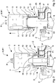
figure 1 is a schematic, partially sectional view of a capsule filling machine according to the invention, in association with a capsule to be filled and in which a dosing turret is in a first working position and in a raised position; -
figure 2 is a partial and enlarged view of the machine offigure 1 with the dosing turret in a lowered position to allow a first dosing unit to draw a product dose from a reservoir; -
figure 3 is a partial and enlarged view of the machine offigure 1 with the dosing turret in a raised position and the first dosing unit provided with a product dose; -
figure 4 shows an enlarged view of the dosing unit offigure 3 with the piston in a first internal position and a second internal position respectively; -
figure 5 is a partial and enlarged view of the machine offigure 1 with the dosing turret rotated in a second working position and in the raised position with the first dosing unit provided with the product dose overlapped and aligned to a capsule body to be filled; -
figure 6 is a partial and enlarged view of the machine offigure 5 with the dosing turret in the lowered position, the first dosing unit adjacent to the capsule body and a second dosing unit inserted into the reservoir to draw a product dose; -
figure 7 is a view similar to that offigure 6 , wherein the product dose is ejected from the first dosage unit and released into the capsule body; -
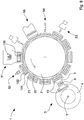
figure 8 is a schematic and simplified plan view from above of the machine according to the invention. - Referring to
figure 8 , a filling machine 1 according to the invention is shown, the filling machine is suitable for fillingcapsules 100, hard gelatin capsules or similar containers with powder, granules, micro-tablets, delayed-action drugs or the like, and in particular with a pharmaceutical or food product. - The filling machine 1 comprises a
transfer turret 2 and a plurality of operating stations, arranged stationary around thetransfer turret 2 itself. More particularly, the filling machine 1 comprises aninlet station 51 in which 100 empty capsules enter the filling machine 1, an opening andcontrol station 52 where thecapsules 100 are opened and controlled, adosing station 3 wherebodies 101 ofcapsules 100 are filled with a product dose PI, aclosure station 54 where thecapsules 100 are closed and anexit station 55 where the filledcapsules 100 are discharged from the filling machine 1. - Advantageously, the filling machine 1 also includes a
waste removal station 53, for example located upstream of theclosing station 54 with respect to the rotation direction of thetransfer turret 2, where non-compliantcapsules 100 are discarded. Also, advantageously, the filling machine 1 comprises a cleaning station downstream of theoutput station 55 and upstream of thecapsule input station 51 with respect to the direction of rotation of thetransfer turret 2, wherefirst seats 21 and/or secondtransfer turret seats 22 are cleaned prior to housingsubsequent capsules 100. - Referring to
figures 1 and7 , thetransfer turret 2 can be rotated around a respective axis, in particular vertical, and is provided withfirst seats 21 andsecond seats 22 to respectively accommodate thebodies 101 and thecaps 102 of thecapsules 100; the latter being previously opened in the opening andcontrol station 52, which is located upstream of thedosing station 3, with reference to the rotational direction of saidtransfer turret 2. - The
dosing station 3 is arranged to fill the bodies of thecapsules 100 with a predetermined dose PI of the above-mentioned product P taken from areservoir 4 and comprises adosing turret 5 rotating around a rotation axis X, which in particular is vertical, between a first working position W1 and a second working position W2. Additionally,dosing turret 3 is linearly movable along the X rotation axis between a lowered position A and a raised position B. - The
dosing station 3 includes at least afirst dosing unit 10 mounted on saiddosing turret 5 and comprising a firsthallow dosing cylinder 12 having an opening 12a at one lower end and arespective piston 13 sliding within thedosing cylinder 12. Thepiston 13 is in particular, movable at least between a first internal position D where it forms within thedosing cylinder 12 adosing chamber 15 suitable for collecting and retaining a product dose PI from thereservoir 4, and an ejection position E in which thepiston 13, more precisely a working end of thepiston 13, substantially faces alower opening 12a of thedosing cylinder 12 to push the product dose PI out of thedosing cylinder 12 and release it into thebody 101 of acapsule 100. - The
dosing cylinder 12 and thepiston 13 of thefirst dosing unit 10 are mounted on thedosing turret 5 substantially parallel to the axis of rotation X. - A first electrical
linear actuator 6 is provided and associated with thedosing turret 5 connected to thefirst dosing unit 10 to move therespective piston 13 into thedosing cylinder 12 along a direction parallel to the axis of rotation X between the first internal position D and the ejection position E. - This first electrical
linear actuator 6 comprises a movable slider directly connected to thepiston 13. - The first electrical
linear actuator 6 also allows to adjust the first internal position D of thepiston 13 with respect to thelower opening 12a of thedosing cylinder 12 so as to modify a volume of thedosing chamber 15 and then the volume of the dose PI of product P to be dosed. - The
reservoir 4 includes, for example, a container provided with anannular housing 24 disposed to hold the product P and closed at the top by acover 25 provided with ahole 26 for the introduction of thedosing cylinder 12 of thefirst dosing unit 10. Thereservoir 4 can rotate around a vertical axis Y so as to present to the first dosing unit 10 a product layer P within theannular chamber 24 of constant height and suitable for a correct filling of thedosing cylinder 12. - The
dosing station 3 is arranged so as to comprise at least one second dosing unit and at least one second electrical linear actuator. For example, in the embodiment illustrated in the figures, thedosing station 3 includes asecond dosing unit 11 mounted on thedosing turret 5, identical to thefirst dosing unit 10 and angularly spaced from the latter by the rotation axis X, in particular spaced by 180°, i.e. substantially opposite to said rotation axis X. A second electricallinear actuator 7, identical to the first electricallinear actuator 6, is mounted on thedosing turret 5 and connected to thesecond dosing unit 11 so as to move thepiston 13 of the latter into therespective dosing cylinder 12. - The second electrical
linear actuator 7 also allows to adjust the first internal position D of thepiston 13 with respect to thelower opening 12a of thedosing cylinder 12 so as to modify a volume of thedosing chamber 15 and then the volume of the PI product dose to be dosed. - The
dosing cylinder 12 and thepiston 13 of thesecond dosing unit 11 are mounted on thedosing turret 5 substantially parallel to the axis of rotation X. - The two electrical
linear actuators - Preferably, the magnetic electric motor slider slides along an axis parallel to the
piston axis 13. - In a different embodiment of the filling machine 1 not shown in the figures, the
dosing turret 5 includes a plurality offirst dosing units 10 parallel to each other and angularly and regularly spaced with respect to the rotation axis X so as to form a first group of (first)dosing units 10 and a plurality ofsecond dosing units 11 parallel to each other and angularly and regularly spaced with respect to the rotation axis X to form a second group of (second)dosing units 11 opposed, i.e. rotated at 180°, with respect to said first group of (first) dosing units. The number of thefirst dosing units 10 is equal to the number ofdosing units 11 and equal to the number ofcapsule bodies 101 housed in thefirst seats 21 of thetransfer turret 2 to be filled in a single operation or phase. The angular pitch or angular distance between twoadjacent dosing units 10, 11 (in both groups) is equal to the pitch or angular distance between the two firstadjacent seats 21 adjacent to thetransfer turret 2. - In this embodiment of the machine, the first electrical
linear actuator 6 and the second electricallinear actuator 7 are respectively connected to the plurality of thedosing units 10 and to the plurality ofsecond dosing units 11 so as to move theirrespective pistons 13. In particular, thepistons 13 of thefirst dosing units 10 are connected to each other and to the first electricallinear actuator 6 by a first connecting element so as to move together. Similarly, thepistons 13 of thesecond dosing units 11 are connected to each other and to the second electricallinear actuator 7 by a second connection element so as to move together. - In a different embodiment, the
pistons 13 of thefirst dosing units 10 and thesecond dosing units 11 are mutually disconnected and eachpiston 13 is coupled to and moved by a respective first or second electricallinear actuator piston 13 can be independently controlled. - In another embodiment of the filling machine 1 not shown in the figures, the
dosing turret 5 includes only a plurality offirst dosing units 10 which are angularly and regularly spaced about the rotation axis X, the first electricallinear actuator 6 being connected to the saidfirst dosing units 10 so as to move theirrespective pistons 13. Also in this embodiment, the number of thefirst dosing units 10 is equal to the number ofbodies 101 of thecapsules 100 housed in thefirst seats 21 of thetransfer turret 2 and to be filled in a single operation or phase. The pitch or angular distance between the first two adjacent dosing units is equal to the pitch or angular distance between the two firstadjacent seats 21 adjacent to thetransfer turret 2. - The filling machine 1 further comprises air suction means 35 connected to the
dosing units 10 byrespective ducts 36 in order to suck air from the inside of thedosing cylinders 12 and cooperate in order to draw the dose PI during the drawing of the product P from thereservoir 4 and to hold it inside thedosing chambers 15, particularly during the rotation of thedosing turret 5, as best explained in the following description. - The
piston 13 of thedosing units linear actuators lower opening 12a with respect to the first internal position D) a volume of thedosing chamber 15 formed by thepiston 13 with its relativehollow dosing cylinder 12 is incrementally increased to move more within thedosing cylinder 12 the product dose PI drawn from thereservoir 4. In practice, the dose PI of the product P moves away from thelower opening 12a. The displacement of thepiston 13 inside thedosing cylinder 11 substantially causes an "intake effect" and dragging of the product dose PI within thedosing chamber 15 which allows to move a peripheral portion of said dose away from thelower opening 12a of thedosing cylinder 12. In this manner, as best described in the following description, during the rotation of thedosing turret 5 for aligning thedosing unit 10 with thebody 101 of the capsule to be filled, the peripheral portion of the dose PI, as it is completely contained within thecylinder 12 and adheres to the inner walls of the latter, can hardly detach and fall from thedosing cylinder 12 due to air flows and/or vibrations generated by the rotation of thedosing turret 5. - According to a particularly advantageous aspect of the invention, during the withdrawal of product P from the
reservoir 4, the electricallinear actuators respective pistons 13 so that the operating end of saidrespective pistons 13 is substantially flush with thelower opening 12a of the respective dosing cylinder 12 (ejection position E) when the operating end contacts the product P in thereservoir 4, when thedosing turret 3 moves from the raised position B to the lowered position A. Further, the electricallinear actuators respective pistons 13 to move from the ejecting position E to the first internal position D while thedosing turret 3 moves towards the lowered position A. In particular, the electricallinear actuators respective pistons 13 so that they move with a rise rate of substantially the same form, but towards the opposite, in respect of a lowering speed of thedosing turret 3 from the raised position B to the lowered position A. - According to this particularly advantageous aspect of the invention, the presence of air inside the
dosing chamber 15 is considerably reduced before the collection of the product, so as to reduce, if not eliminate, dust problems during the dosage of the dose P1. - An
electric actuator 8 is provided for moving thedosing turret 5 along the axis of rotation X and to rotate thedosing turret 5 around the rotation axis X between the first working position W1, wherein thefirst dosing unit 10 is capable of collecting a product dose PI from thereservoir 4 and the second working position W2, wherein thefirst dosing unit 10 is capable of transferring and releasing the product dose PI into thecap 101 of acapsule 100. - During the running of the filling machine 1 of this invention, in the first working position W1 of the dosing turret, the second dosing unit 11 (as opposed to the first dosing unit 10) is capable of transferring and releasing a respective product dose PI into a
body 101 of acapsule 100, while in the second working position W2, thesecond dosing unit 11 is able to draw a product dose PI from thereservoir 4. - The
electric actuator 8, which includes, for example, an electrically rotolinear brushless motor, is arranged to move thedosing turret 5 along the axis X and rotate thedosing turret 5 between the two working positions W1, W2 of an angle of about 180°, with an intermittent rotating motion in the opposite directions of rotation. In other words, thedosing turret 5 is rotated alternately 180° clockwise and then counter-clockwise (for example, it is rotated clockwise from the first working position W1 to the second working position W2 and counter-clockwise from the second working position W2 to the first working position W1). Thus, in the absence of progressive rotation in a single direction of rotation, such as in intermittent mechanical drives, no collector or distributor rotation is required to provide the pneumatic and / or electrical supply for devices and / or sensors mounted on said dosing turret, thereby allowing to simplify the structure and operation of the filling machine 1. - In a different embodiment of the filling machine 1 of the invention not shown in the figures, mechanical levelling screeds (blade) or pneumatic (air blowing) are arranged to remove excess product at the
lower opening 12a of thedosing cylinder 12 and detach the material in excess of the dose PI when thedosing unit reservoir 4 in the raised position B of the dosing turret with thepiston 13 arranged in the first internal position D. When the excess product is removed, thepiston 13 is moved in the second internal position F so as to bring the product dose PI completely into thedosing cylinder 12. - The operation of the filling machine 1 of the invention and in particular of the
dosing station 3 comprises a first step (Figure 1 ) in which thedosing turret 5 is in the raised position B and rotated in the first working position W1, in which thefirst dosing unit 10 is above the product P in thereservoir 4. - Firstly, the electrical
linear actuators pistons 13 of thedosing units lower openings 12a of thecorresponding dosing cylinders 12, forming within the latter thedosage chambers 15 having a predetermined volume equal to that of the dose PI of the product P to be dosed in thecapsules 100. - According an embodiment of the invention, the electrical
linear actuators respective pistons 13 in the ejection position E. - In a second step (
Figure 2 ), thedosing turret 5 is moved linearly along the axis of rotation X from the raised position B to the lowered position A so that thefirst dosing unit 10 can be inserted or "dipped" inside of thereservoir 4, passing through thehole 26 of thecover 25, in the product P layer contained in theannular housing 24. As is known, by inserting thedosing cylinder 12 into the product layer, part of the latter penetrates and compresses, more or less strongly, depending on the kind of product P within thedosing chamber 15. - According to an embodiment of the invention above given, during the second step in which the
dosing turret 5 is moved linearly along the axis of rotation X from the raised position B to the lowered position A, the electricallinear actuators respective pistons 13 from the ejection position E to the first internal position D, with module speed substantially equal but opposite to a lowering speed of thedosing turret 5 from the raised position B to the lowered position A. - The product PI dose is withdrawn from the
reservoir 4, then introduced and retained in thedosing chamber 15 also by means of the air suction carried out within thedosing cylinder 12 by the air suction means 35 connected to thefirst dosing unit 10 through arespective duct 36. - In this second step, the
second dosing unit 11 is superimposed and aligned with afirst seat 21 of thetransfer turret 2, but is free of the product dose P1. - In a third stage (
Figure 3 ), thedosing turret 5 is moved from the lowered position A to the raised position B to disengage thefirst dosing unit 10 from the product P and from thereservoir 4. - At the same time as the lifting motion of the
dosing turret 5, or on completing the latter, thepiston 13 of thefirst dosing unit 10 is moved by the first electricallinear actuator 6 to the second internal position F, so as to increase the volume of thedosing chamber 15 and move the dose PI of product PI drawn from thereservoir 4 more within the inside ofdosing cylinder 12. - The displacement of
piston 13 inside thedosing cylinder 11 causes the suction of the product dose PI within thedosing chamber 15, thereby allowing the peripheral portion of the dose to be moved away from thelower opening 12a of the dosing cylinder 12 (Figure 4 ). - In essence, the first electrical
linear actuator 6 is programmed to allow therelevant piston 13 to be positioned in at least two (different) internal positions, one defining the volume of thedosing chamber 15, and one which defines a safe transport condition of the dose PI, from the first working position W1 to the second working position W2. - It should be noted that the first electrical
linear actuator 6 can be programmed to movepiston 13 from the first internal position D to the second internal position F regardless of the movement of thedosing turret 5 from the lowered position A to the raised position B. Advantageously, the first electricallinear actuator 6 can be programmed to move thepiston 13 from the first internal position D to the second internal position F only once the excess product has been removed. - Further, according to a preferred embodiment, the
dosing station 3 comprises a motorisation (e.g., a brushless motor) for moving thedosing turret 5 from the lowered position A to the raised position B according to a motion law comprising a concurrent stop step when the excess product is removed. - In a subsequent fourth step (
Figure 5 ), thedosing turret 5 in the raised position B is rotated in the second working position W2 wherein thefirst dosing unit 10 is aligned and superimposed on afirst seat 21 of thetransfer turret 2, containing thebody 101 of acapsule 100, while thesecond dosing unit 11 is above thereservoir 4, aligned with thehole 26 of thecap 25. - The displacement of the
piston 13 inside thedosing cylinder 11 from the first internal position D to the second internal position F allows the peripheral portion of dose PI to be fully contained withindosing cylinder 12 during the rotation of the dosing turret 5 (fourth phase), preventing product detachments and losses due to airflows and/or vibrations generated by thedosing turret 5 movement. - The
dosing turret 5 is rotated from the first working position W1 to the second working position W2 for example clockwise rotation with reference to a plan view from the top of the filling machine 1 of the invention. - In a fifth step (
Figure 6 ), thedosing turret 5 is moved in the lowered position A so that thefirst dosing unit 10 can be positioned with thelower opening 12a of thedosing cylinder 12 aligned and substantially facing thecapsule body 101 to be filled with the product dose PI. At the same time, thesecond dosing unit 11 is inserted inside thereservoir 4 in order to draw or load a respective product dose PI. - In a subsequent sixth step (
Figure 7 ), thepiston 13 of thefirst dosing unit 10 is moved by the first electricallinear actuator 6 from the second internal position F to the ejection position E in order to eject the product dose PI from thedosing chamber 15 and transfer it to thebody 101 of thecapsule 100. Air suction (if present) inside thedosing cylinder 12 at this stage is deactivated to allow the ejection of the dose P1. It must be noted that during the ejection of the product dose PI it is not necessary to stop thepiston 13 in the first internal position D and advantageously, it is possible to move thepiston 13 of thefirst dosing unit 10 by means of the first electricallinear actuator 6 in a non-stop stroke between the second internal position F and the ejection position E. Note that through the first electricallinear actuator 6 it is possible to precisely, accurately and repeatedly check the movement of thepiston 13, particularly downstream from the second internal position F to the ejection position E. More in detail, acting on the first electricallinear actuator 6, it is possible to control the motion (speed, acceleration) of thepiston 13 which can be selected and set in function not only of the amount of product to be dosed (volume of dose P1) but also of the type of product to be dosed, e.g. more or less compacted powder, granules, micro-tablets, delayed-action drugs etc. - In a subsequent seventh step, not shown in the figures, the
dosing turret 5 is moved to the raised position B so as to move away thefirst dosing unit 10 from thecapsule body 101 filled with the product dose PI and at the same time disengage thesecond dosing unit 11 from the product P and thereservoir 4. At the same time as the lifting motion of thedosing turret 5, or on completing this, thepiston 13 of thefirst dosing unit 11 is moved by the first electricallinear actuator 7 to the second internal position F, so as to increase the volume of thedosing chamber 15 and move the product dose PI drawn from thereservoir 4 more within the inside ofdosing cylinder 12. - In essence, as described with reference to the first electrical
linear actuator 6, the second electricallinear actuator 7 can also be programmed to allow therespective piston 13 to be positioned in at least two (different) internal positions, one defining thedosing chamber 15, and one that defines a safe transport condition of the dose PI, from the second working position W2 to the first working position W1. - It must also be noted that the first electrical
linear actuator 6 and the second electricallinear actuator 7 can be actuated independently of each other so that optimum motion laws can be chosen to eject the product dose PI towards therespective capsule body 101 and simultaneously to draw and keep the product within thedosing chamber 15 without the motion law of the first electricallinear actuator 6 adversely affecting the motion law of the second electricallinear actuator 7. Advantageously, an optimal motion law can be adopted to let thepiston 13 occupy the second internal position F independently of the motion law adopted to eject the product dose PI. - In a subsequent eighth phase not shown in the figures, the
dosing turret 5 is returned from the second working position W2 to the first working position W1 with a rotation of 180° counter-clockwise, referring to a plan view from above of filling machine1. - In a ninth phase, the
dosing turret 5 is moved from the raised position B to the lowered position A so that thefirst dosing unit 10 can be inserted inside thereservoir 4 to draw or load a respective dose PI of the product and thesecond dosing unit 11 is positioned with thelower opening 12a of thedosing cylinder 12 aligned and substantially facing thecapsule body 101 to be filled with the product dose PI. - In a subsequent tenth phase, the
piston 13 is movable at a second electricalelectric actuator 7 from the second internal position F to the ejection position E, advantageously according to a stroke without intermediate stops, to expel the dose PI released to the respectiveunderlying capsule body 11. - The next step coincides with the third step previously described.
- In the normal operation of the filling machine the steps from the third to the tenth are repeated cyclically.
- Once the body101 of a
capsule 100 has been filled with the product dose PI, thetransfer turret 2 is rotated with a defined angle or pitch so as to position asubsequent capsule body 101 to be filled. - It must be noted that the description of the operation of the filling machine 1 is also the same in the case of a plurality of
first dosing units 10 and a plurality ofsecond dosing units 11 arranged to fill at the same time a plurality of capsule bodies 101 (in number equal to that ofdosing units 10, 11) with respective doses PI of the product so as to increase the productivity of the filling machine 1 of the invention. - The method according to the invention for filling
capsules 100 or similar containers with a product P in powder, granules, mini-tablets, delayed-action drugs or the like comprises: - withdrawing a product dose PI from a
reservoir 4 by means of adosing unit hallow dosing cylinder 12, with anopening 12a at one end, and arespective piston 13 movable inside thedosing cylinder 12 and placed in a first internal position D wherein it forms within thedosing cylinder 12 adosing chamber 15 adapted to receive and retain the product dose PI; - moving the
dosing unit body 101 of acapsule 100 to eject the product dose PI out of thedosing cylinder 12 and release it into thecapsule body 101 by moving thepiston 13 inside thedosing cylinder 12 to an ejection position E; - before moving the
dosing unit piston 13 from its first internal position D to a second internal position F (further away from thelower opening 12a than the first internal position D), where a volume of thedosing chamber 15 is displaced from thelower end 12a, moving the dose PI of the product withdrawn from thereservoir 4 into the inside of thedosing cylinder 12, thereby preventing detachments of product from the dose PI during said moving of thedosing unit - Withdrawing the product dose PI comprises inserting or "diving" the
dosing unit reservoir 4 such that a portion of said product P penetrates and is compressed within thedosage chamber 15 formed by thepiston 13 in thehallow dosing cylinder 12, thus achieving the dose PI of product. - Moving the
dosing unit dosing turret 5 on which saiddosing unit - Advantageously, the method further comprises moving the
piston 13 of thedosing unit linear actuator dosing turret 5. - It is also possible adjust said first internal position D of the
piston 13 in therespective dosing cylinder 12 via the electricallinear actuator dosing chamber 15 and therefore of said product dose PI drawn from thedosing unit - The method further comprises air suction within the
dosing cylinder 12 of thedosing unit reservoir 4 and to retain inside thedosing chamber 15 said dose PI while thedosing unit dosing turret 5 and therefore, ofdosing unit reservoir 4 to thefirst seat 21 of thetransfer turret 2. - Advantageously, according to a preferred embodiment, the method of the invention comprises, during the step of drawing the dose PI in which the
dosing unit reservoir 4, moving thepiston 13 from the ejection position E to the first internal position D. According to such a preferred embodiment, it is foreseen that thepiston 13 moves from the ejecting position E to the first internal position D with a module speed substantially equal but in the opposite direction at a lowering speed of thedosing turret 5 from a raised position B to a lowered position A. - In an embodiment of the filling method of the invention, after drawing the product dose PI and before moving the
piston 13 into the second internal position F, it is possible to remove excess product from thelower opening 12a of thedosing cylinder 12 of thedosing unit - Removing excess product from the
lower opening 12a of thedosing cylinder 12 of thedosing unit lower opening 12a. Alternatively, removing excess product from thelower opening 12a of thedosing cylinder 12 of thedosing unit dosing cylinder 12 at thelower opening 12a between a non-interference position with the saidlower opening 12a and a closure position with thelower opening 12a. In essence, in the passage between the non-interference position and the closure position, the removal of excess product from thelower opening 12a is carried out. - The machine and the method of the invention allow to reliably, accurately, and repeatedly fill capsules, caps or similar elements even with products which are difficult to compact and/or compress such as granules, micro-tablets or delayed-action drugs.
- Due to the electrical
linear actuators dosing turret 4, it is possible to move thepiston 13 of eachdosing unit dosing turret 5 around and along the rotation axis X. - The
piston 13 can be moved, particularly in the ejection stroke of dose PI from thedosing cylinder capsule body 101 with extreme precision, for example controlling the law of motion (speed, acceleration) which can be selected and set in operation, not only for the quantity of product to be dosed (volume of dose P1), but also for the type of product to be dosed, e.g. more or less compacted powder, granules, micro-tablets, delayed-action drugs, etc. - In addition, the electrical
linear actuator 6 allows to rapidly and accurately vary, for example by software, the first internal position D of thepiston 13 with respect to thelower opening 12a of thedosing cylinder 12 so as to modify a volume of thedosing chamber 15 and then a volume or amount of the dose PI of the product to be dosed. - Advantageously, the electrical
linear actuator 6 allows to adjust, for example by software, rapidly and accurately, the second internal position F of thepiston 13 with respect to thelower opening 12a of thedosing cylinder 12. - Finally, the electrical
linear actuator 6 allows to move, separately and independently of the aforesaid filling machines,piston 13 of thedosing units dosing chamber 15 and move the product dose PI drawn from thereservoir 4 more within thedosing cylinder 12. - As previously pointed out, the
piston retraction movement 13 inside thedosing cylinder 12 causes drainage by "suction" of the product dose PI within thedosing chamber 15, which allows to move away the peripheral portion of the dose PI from thelower opening 12a of thedosing cylinder 12. In this way, during the rotation of the dosing turret 5 (to align thedosing unit first seat 21 of the transfer turret 2), the peripheral portion of the dose PI is completely contained within thedosing cylinder 12 and, adhering to the inner walls of the latter, it can hardly detach itself due to airflows and/or vibrations generated by the movement of thedosing turret 5. - The above solution is particularly advantageous in the case of products P in the form of granules, micro-tablets, delayed-action drugs which are more difficult to compress within the
dosing cylinder 12 and therefore more likely to escape during the displacement of thedosing unit dosing turret 5. - Due to the use of electrical linear actuators for the
pistons 13 of thedosing units electric motor 8 for the shift and rotation of thedosing turret 5, the filling machine 1 of the invention, in addition to offering a high performance, has a particularly simple, economical and robust structure and versatile, reliable and safe operation. In particular, the use of the rotaryelectric motor 8 allows the turret to be moved along its axis of rotation and to rotate thedosing turret 5 between the two operating positions W1, W2 at an angle of about 180°, with an intermittent rotating motion in the opposite directions of rotation, i.e. the dosing turret can be rotated alternately by 180° clockwise and then counter-clockwise. In this way, in the absence of a progressive rotation in a single direction of rotation, there is no need for collectors, or distributors, rotators and / or electric motors with sliding contacts to carry out the pneumatic and / or electrical supply of the devices and / or sensors mounted on the aforementioned dosing turret, thereby simplifying the structure and operation of the filling machine as well as increasing its reliability.
Claims (15)
- A machine (1) for filling capsules (100) or similar containers with a product comprising a rotating transfer turret (2) arranged to transfer said capsules (100) through adjacent operating stations and provided with seats (21, 22) for housing capsule bodies (101) and capsule caps (102) of said capsules (100), and at least one dosing station (3) arranged to fill said capsule bodies (101) with a product (P) drawn from a reservoir (4) and comprising of a dosing turret (5) rotating around a rotation axis (X) and moving along said axis (X) between a lowered position (A) and a raised position (B), at least one first dosing unit (10) associated with said dosing turret (5), said dosing unit comprising an hallow dosing cylinder (12) having an opening (12a) at a lower end and a piston (13) movable within the dosing cylinder (12) at least between a first internal position (D), in which the piston (13) forms inside said dosing cylinder (12) a dosing chamber (15), between the piston (13) and said opening (12a), for drawing a dose (P1) of product (P) from said reservoir (4) and retaining it, and an ejection position (E) for ejecting said dose (P1) of product (P) out of said dosing cylinder (12) and releasing it into the body (101) of the capsule (100), characterised by including a first electrical linear actuator (6) associated to said turret (5) and connected to said first dosing unit (10) and configured to move the piston (13) between said first internal position (D) and said ejection position (E).
- Machine according to Claim 1, comprising at least one second dosing unit (11) mounted on the dosing turret (5), identical to said first dosing unit (10) and angularly spaced from the axis of rotation (X), in particular distanced by 180°, and at least a second electrical linear actuator (7) connected to said second dosing unit (11) for moving the piston (13) between said first internal position (D) and said ejection position (E).
- Machine according to any one of the preceding claims, wherein the dosing turret (5) includes a plurality of first dosing units (10) angularly spaced around the axis of rotation (X), the first electrical linear actuator (6) being connected to said plurality of first dosing units (10) and arranged to move the respective pistons (13) of said plurality of first dosing units (10).
- Machine according to any one of the preceding claims, wherein the first electrical linear actuator (6) comprises a linear electric motor.
- Machine according to any one of the preceding claims, wherein the first electrical linear actuator (6) comprises a rotary electric motor coupled to a screw-nut drive system.
- The machine according to any of the preceding claims, wherein said piston (13) is movable from the first electrical linear actuator (6) from the first internal position (D) to a second internal position (F) further away from said opening (12a), said dosage chamber (15) increasing so that the product (P) dose (P) drawn from said reservoir (4) is moved away from the opening (12a).
- Machine according to any of the preceding claims, comprising an electric actuator (8) preferably a rotary engine for moving the dosing turret (5) along the axis of rotation (X) and rotating the dosing turret (5) around the axis (X), in particular with intermittent rotating motion in the two opposite directions of rotation, between a first operating position (W1), wherein the first dosing unit (10) is suitable for drawing a dose (P1) of product (P) from said reservoir (4), and a second operative position (W2), wherein said first dosing unit (10) is suitable for transferring and releasing said product dose (P1) of product (P) into a capsule body (101) of a capsule (100).
- Machine according to any one of the preceding claims, comprising air suction means (35) connected to the first dosing unit (10) by means of a duct (36) for sucking air from the inside of the dosing cylinder (12) and for cooperating for drawing and retaining the dose (P1) of product (P) within said dosing chamber (15).
- Machine according to any one of the preceding claims, wherein said first electrical linear actuator (6) comprises a movable slider directly connected to the first piston (13).
- Method for filling capsules (100) or similar containers with a powder (P) product, granules, micro-tablets, delayed-action drugs or the like, comprising:- withdrawing a product (P) dose (P1) from a reservoir (4) by means of a dosing unit (10, 11) comprising ah hallow dosing cylinder (12) with an opening (12a) at one end and a piston (13) movable within the dosing cylinder (12), said piston (13) being arranged in a first internal position (D) to form within said dosing cylinder (12) between the piston (13) and said opening 12 a dosing chamber (15) adapted to receive and retain said product (P) dose (P1);- moving said dosing unit (10, 11) to a body (101) of a capsule (100) and eject said product dose (P1) out of said dosing cylinder (12) to release said product dose (P1) into said body (101) by moving said piston (13) inside said dosing cylinder (12) to an ejection position (E),characterised by the fact that the movement of the piston (13) from said first internal position (D) to said ejection position (E) is carried out by means of an electrical linear actuator (6, 7) connected to said dosing unit (10, 11).
- Method according to claim 10, wherein the piston movement (13) between said first internal position (D) and said ejection position (E) is performed by means of an electric linear motor (6, 7).
- Method according to claim 10 or 11, wherein after withdrawing the product (P) dose (P1) from the reservoir (4), said piston (13) is further moved from said first internal position (D) to a second internal position (F) farther away from said opening (12a), wherein a volume of said dosage chamber (15) is increased to allow said product dose (P) withdrawn from said reservoir (4) to move away from said opening (12a).
- Method according to Claim 12, wherein the piston movement (13) between said first internal position (D) and said second internal position (F) is carried out by means of a linear electric motor (6, 7).
- Method according to any one of claims 10 to 13, comprising sucking air from the inside of the dosing cylinder (12) of the dosing unit (10, 11) to help the withdrawal of said product dose (P1) from the reservoir (4) and to retain within said dosing chamber (15) said product dose (P1) during said moving of the dosing unit (10, 11).
- Method according to any one of claims 10 to 14, comprising, when drawing a product dose (P1) from a reservoir (4), moving the piston (13) from the ejection position (E) to the first internal position (D).
Applications Claiming Priority (1)
| Application Number | Priority Date | Filing Date | Title |
|---|---|---|---|
| IT102016000093360A IT201600093360A1 (en) | 2016-09-16 | 2016-09-16 | Machine and method for filling capsules. |
Publications (2)
| Publication Number | Publication Date |
|---|---|
| EP3295920A1 true EP3295920A1 (en) | 2018-03-21 |
| EP3295920B1 EP3295920B1 (en) | 2020-12-23 |
Family
ID=57909879
Family Applications (1)
| Application Number | Title | Priority Date | Filing Date |
|---|---|---|---|
| EP17190027.7A Active EP3295920B1 (en) | 2016-09-16 | 2017-09-08 | Machine for filling capsules and related method |
Country Status (3)
| Country | Link |
|---|---|
| EP (1) | EP3295920B1 (en) |
| ES (1) | ES2857812T3 (en) |
| IT (1) | IT201600093360A1 (en) |
Cited By (8)
| Publication number | Priority date | Publication date | Assignee | Title |
|---|---|---|---|---|
| WO2020141416A1 (en) * | 2019-01-02 | 2020-07-09 | Scitech Centre | Tamping asssembly for capsule filling machine |
| WO2021014399A1 (en) * | 2019-07-24 | 2021-01-28 | Scitech Centre | Smart tamping system for dosage optimization in capsule filling machine |
| CN113244111A (en) * | 2021-05-20 | 2021-08-13 | 宁波易合医药有限公司 | Device for accurately filling dry powder |
| IT202000008962A1 (en) * | 2020-04-24 | 2021-10-24 | Romaco Srl | EQUIPMENT FOR FILLING CONTAINERS WITH A POWDER MATERIAL |
| IT202000010855A1 (en) * | 2020-05-13 | 2021-11-13 | Ima Spa | MACHINE TO FILL CAPSULES. |
| CN114144153A (en) * | 2019-07-22 | 2022-03-04 | I·M·A·工业机械自动装置股份公司 | Machine and method for filling capsules |
| CN114699319A (en) * | 2022-03-04 | 2022-07-05 | 徐爱云 | Full-automatic enteric hollow capsule medicine continuous filling equipment |
| WO2023139114A1 (en) | 2022-01-19 | 2023-07-27 | Capsugel Belgium Nv | Device for dosing solid particulate material |
Citations (2)
| Publication number | Priority date | Publication date | Assignee | Title |
|---|---|---|---|---|
| EP1052961A1 (en) * | 1998-12-03 | 2000-11-22 | I.M.A. INDUSTRIA MACCHINE AUTOMATICHE S.p.A. | A checking and controlling apparatus for use in capsule-packaging machines |
| EP2090279A1 (en) * | 2008-02-18 | 2009-08-19 | MG2 S.r.l. | Machine for filling containers with at least one product. |
-
2016
- 2016-09-16 IT IT102016000093360A patent/IT201600093360A1/en unknown
-
2017
- 2017-09-08 EP EP17190027.7A patent/EP3295920B1/en active Active
- 2017-09-08 ES ES17190027T patent/ES2857812T3/en active Active
Patent Citations (2)
| Publication number | Priority date | Publication date | Assignee | Title |
|---|---|---|---|---|
| EP1052961A1 (en) * | 1998-12-03 | 2000-11-22 | I.M.A. INDUSTRIA MACCHINE AUTOMATICHE S.p.A. | A checking and controlling apparatus for use in capsule-packaging machines |
| EP2090279A1 (en) * | 2008-02-18 | 2009-08-19 | MG2 S.r.l. | Machine for filling containers with at least one product. |
Cited By (19)
| Publication number | Priority date | Publication date | Assignee | Title |
|---|---|---|---|---|
| WO2020141416A1 (en) * | 2019-01-02 | 2020-07-09 | Scitech Centre | Tamping asssembly for capsule filling machine |
| US11951076B2 (en) | 2019-07-22 | 2024-04-09 | I.M.A. Industria Macchine Automatiche S.P.A. | Machine and method for filling capsules |
| CN114144153B (en) * | 2019-07-22 | 2023-12-29 | I·M·A·工业机械自动装置股份公司 | Machine and method for filling capsules |
| CN114144153A (en) * | 2019-07-22 | 2022-03-04 | I·M·A·工业机械自动装置股份公司 | Machine and method for filling capsules |
| CN114302849A (en) * | 2019-07-24 | 2022-04-08 | 赛特科技中心 | Intelligent tamping system for dosage optimization of capsule filling machine |
| WO2021014399A1 (en) * | 2019-07-24 | 2021-01-28 | Scitech Centre | Smart tamping system for dosage optimization in capsule filling machine |
| US12037146B2 (en) | 2019-07-24 | 2024-07-16 | Scitech Centre | Smart tamping system for dosage optimization in capsule filling machine |
| CN114302849B (en) * | 2019-07-24 | 2023-11-07 | 赛特科技中心 | Intelligent tamping system for dose optimization of capsule filling machine |
| WO2021214808A1 (en) * | 2020-04-24 | 2021-10-28 | Romaco S.R.L. | Apparatus for filling containers with a powdered material |
| IT202000008962A1 (en) * | 2020-04-24 | 2021-10-24 | Romaco Srl | EQUIPMENT FOR FILLING CONTAINERS WITH A POWDER MATERIAL |
| KR20230009962A (en) * | 2020-05-13 | 2023-01-17 | 아이.엠.에이. 인듀스트리아 마친 오토메티크 에스.피.에이. | capsule filling machine |
| WO2021229426A1 (en) * | 2020-05-13 | 2021-11-18 | I.M.A. Industria Macchine Automatiche S.P.A. | Filling machine for filling capsules |
| IT202000010855A1 (en) * | 2020-05-13 | 2021-11-13 | Ima Spa | MACHINE TO FILL CAPSULES. |
| US12048673B2 (en) | 2020-05-13 | 2024-07-30 | I.M.A. Industria Macchine Automatiche S.P.A. | Filling machine for filling capsules |
| KR102763863B1 (en) | 2020-05-13 | 2025-02-07 | 아이.엠.에이. 인듀스트리아 마친 오토메티크 에스.피.에이. | capsule filling machine |
| CN113244111A (en) * | 2021-05-20 | 2021-08-13 | 宁波易合医药有限公司 | Device for accurately filling dry powder |
| WO2023139114A1 (en) | 2022-01-19 | 2023-07-27 | Capsugel Belgium Nv | Device for dosing solid particulate material |
| CN114699319A (en) * | 2022-03-04 | 2022-07-05 | 徐爱云 | Full-automatic enteric hollow capsule medicine continuous filling equipment |
| CN114699319B (en) * | 2022-03-04 | 2023-08-04 | 山西广生胶囊有限公司 | Full-automatic enteric hollow capsule medicine continuous filling equipment |
Also Published As
| Publication number | Publication date |
|---|---|
| ES2857812T3 (en) | 2021-09-29 |
| EP3295920B1 (en) | 2020-12-23 |
| IT201600093360A1 (en) | 2018-03-16 |
Similar Documents
| Publication | Publication Date | Title |
|---|---|---|
| EP3295920B1 (en) | Machine for filling capsules and related method | |
| EP2791012B1 (en) | Device and method for dispensing and packing solid substances | |
| CN102227201B (en) | Machine and method for filling and weighing capsules | |
| EP3057871B1 (en) | Unit and method for filling containing elements of single-use capsules for extraction or infusion beverages | |
| CN106163935A (en) | Unit and method for filling containers forming single-use capsules for extraction or infusion beverages | |
| EP2648786B1 (en) | Apparatus for dispensing powder | |
| CN114302849B (en) | Intelligent tamping system for dose optimization of capsule filling machine | |
| EP2671807B1 (en) | A device for transferring pharmaceutical articles from a counter to continuously advancing containers | |
| EP4149408B1 (en) | Filling machine for filling capsules | |
| JP6373981B2 (en) | A unit and method for filling container elements of disposable capsules for extraction or infusion beverages. | |
| EP3620150B1 (en) | A tamping assembly | |
| EP0488794B1 (en) | Collating apparatus | |
| KR102850503B1 (en) | Machine and method for filling capsules | |
| EP1906908B1 (en) | Intermittent motion capsule filling machine | |
| CN106604868A (en) | Unit and method for filling a containment element of a disposable balloon | |
| KR102922419B1 (en) | Purified dispensing device and method | |
| EP3263467B1 (en) | A filling machine for capsules | |
| EP3790805B1 (en) | A tamping assembly | |
| IT202300011007A1 (en) | Capsule dosing apparatus, machine and method for filling capsules. | |
| WO2025172820A1 (en) | Machine for filling capsules | |
| ITFI970070A1 (en) | MACHINE FOR FILLING GELATIN CAPSULES OR OTHER, WITH PRODUCTS IN GRANULES OR POWDER |
Legal Events
| Date | Code | Title | Description |
|---|---|---|---|
| PUAI | Public reference made under article 153(3) epc to a published international application that has entered the european phase |
Free format text: ORIGINAL CODE: 0009012 |
|
| STAA | Information on the status of an ep patent application or granted ep patent |
Free format text: STATUS: THE APPLICATION HAS BEEN PUBLISHED |
|
| AK | Designated contracting states |
Kind code of ref document: A1 Designated state(s): AL AT BE BG CH CY CZ DE DK EE ES FI FR GB GR HR HU IE IS IT LI LT LU LV MC MK MT NL NO PL PT RO RS SE SI SK SM TR |
|
| AX | Request for extension of the european patent |
Extension state: BA ME |
|
| STAA | Information on the status of an ep patent application or granted ep patent |
Free format text: STATUS: REQUEST FOR EXAMINATION WAS MADE |
|
| 17P | Request for examination filed |
Effective date: 20180921 |
|
| RBV | Designated contracting states (corrected) |
Designated state(s): AL AT BE BG CH CY CZ DE DK EE ES FI FR GB GR HR HU IE IS IT LI LT LU LV MC MK MT NL NO PL PT RO RS SE SI SK SM TR |
|
| GRAP | Despatch of communication of intention to grant a patent |
Free format text: ORIGINAL CODE: EPIDOSNIGR1 |
|
| STAA | Information on the status of an ep patent application or granted ep patent |
Free format text: STATUS: GRANT OF PATENT IS INTENDED |
|
| INTG | Intention to grant announced |
Effective date: 20201002 |
|
| GRAS | Grant fee paid |
Free format text: ORIGINAL CODE: EPIDOSNIGR3 |
|
| GRAA | (expected) grant |
Free format text: ORIGINAL CODE: 0009210 |
|
| STAA | Information on the status of an ep patent application or granted ep patent |
Free format text: STATUS: THE PATENT HAS BEEN GRANTED |
|
| AK | Designated contracting states |
Kind code of ref document: B1 Designated state(s): AL AT BE BG CH CY CZ DE DK EE ES FI FR GB GR HR HU IE IS IT LI LT LU LV MC MK MT NL NO PL PT RO RS SE SI SK SM TR |
|
| REG | Reference to a national code |
Ref country code: GB Ref legal event code: FG4D |
|
| REG | Reference to a national code |
Ref country code: DE Ref legal event code: R096 Ref document number: 602017029907 Country of ref document: DE |
|
| REG | Reference to a national code |
Ref country code: AT Ref legal event code: REF Ref document number: 1347014 Country of ref document: AT Kind code of ref document: T Effective date: 20210115 |
|
| REG | Reference to a national code |
Ref country code: IE Ref legal event code: FG4D |
|
| PG25 | Lapsed in a contracting state [announced via postgrant information from national office to epo] |
Ref country code: NO Free format text: LAPSE BECAUSE OF FAILURE TO SUBMIT A TRANSLATION OF THE DESCRIPTION OR TO PAY THE FEE WITHIN THE PRESCRIBED TIME-LIMIT Effective date: 20210323 Ref country code: RS Free format text: LAPSE BECAUSE OF FAILURE TO SUBMIT A TRANSLATION OF THE DESCRIPTION OR TO PAY THE FEE WITHIN THE PRESCRIBED TIME-LIMIT Effective date: 20201223 Ref country code: GR Free format text: LAPSE BECAUSE OF FAILURE TO SUBMIT A TRANSLATION OF THE DESCRIPTION OR TO PAY THE FEE WITHIN THE PRESCRIBED TIME-LIMIT Effective date: 20210324 Ref country code: FI Free format text: LAPSE BECAUSE OF FAILURE TO SUBMIT A TRANSLATION OF THE DESCRIPTION OR TO PAY THE FEE WITHIN THE PRESCRIBED TIME-LIMIT Effective date: 20201223 |
|
| REG | Reference to a national code |
Ref country code: AT Ref legal event code: MK05 Ref document number: 1347014 Country of ref document: AT Kind code of ref document: T Effective date: 20201223 |
|
| REG | Reference to a national code |
Ref country code: NL Ref legal event code: MP Effective date: 20201223 |
|
| PG25 | Lapsed in a contracting state [announced via postgrant information from national office to epo] |
Ref country code: SE Free format text: LAPSE BECAUSE OF FAILURE TO SUBMIT A TRANSLATION OF THE DESCRIPTION OR TO PAY THE FEE WITHIN THE PRESCRIBED TIME-LIMIT Effective date: 20201223 Ref country code: BG Free format text: LAPSE BECAUSE OF FAILURE TO SUBMIT A TRANSLATION OF THE DESCRIPTION OR TO PAY THE FEE WITHIN THE PRESCRIBED TIME-LIMIT Effective date: 20210323 Ref country code: LV Free format text: LAPSE BECAUSE OF FAILURE TO SUBMIT A TRANSLATION OF THE DESCRIPTION OR TO PAY THE FEE WITHIN THE PRESCRIBED TIME-LIMIT Effective date: 20201223 |
|
| PG25 | Lapsed in a contracting state [announced via postgrant information from national office to epo] |
Ref country code: NL Free format text: LAPSE BECAUSE OF FAILURE TO SUBMIT A TRANSLATION OF THE DESCRIPTION OR TO PAY THE FEE WITHIN THE PRESCRIBED TIME-LIMIT Effective date: 20201223 Ref country code: HR Free format text: LAPSE BECAUSE OF FAILURE TO SUBMIT A TRANSLATION OF THE DESCRIPTION OR TO PAY THE FEE WITHIN THE PRESCRIBED TIME-LIMIT Effective date: 20201223 |
|
| REG | Reference to a national code |
Ref country code: LT Ref legal event code: MG9D |
|
| PG25 | Lapsed in a contracting state [announced via postgrant information from national office to epo] |
Ref country code: SK Free format text: LAPSE BECAUSE OF FAILURE TO SUBMIT A TRANSLATION OF THE DESCRIPTION OR TO PAY THE FEE WITHIN THE PRESCRIBED TIME-LIMIT Effective date: 20201223 Ref country code: RO Free format text: LAPSE BECAUSE OF FAILURE TO SUBMIT A TRANSLATION OF THE DESCRIPTION OR TO PAY THE FEE WITHIN THE PRESCRIBED TIME-LIMIT Effective date: 20201223 Ref country code: PT Free format text: LAPSE BECAUSE OF FAILURE TO SUBMIT A TRANSLATION OF THE DESCRIPTION OR TO PAY THE FEE WITHIN THE PRESCRIBED TIME-LIMIT Effective date: 20210423 Ref country code: EE Free format text: LAPSE BECAUSE OF FAILURE TO SUBMIT A TRANSLATION OF THE DESCRIPTION OR TO PAY THE FEE WITHIN THE PRESCRIBED TIME-LIMIT Effective date: 20201223 Ref country code: CZ Free format text: LAPSE BECAUSE OF FAILURE TO SUBMIT A TRANSLATION OF THE DESCRIPTION OR TO PAY THE FEE WITHIN THE PRESCRIBED TIME-LIMIT Effective date: 20201223 Ref country code: SM Free format text: LAPSE BECAUSE OF FAILURE TO SUBMIT A TRANSLATION OF THE DESCRIPTION OR TO PAY THE FEE WITHIN THE PRESCRIBED TIME-LIMIT Effective date: 20201223 Ref country code: LT Free format text: LAPSE BECAUSE OF FAILURE TO SUBMIT A TRANSLATION OF THE DESCRIPTION OR TO PAY THE FEE WITHIN THE PRESCRIBED TIME-LIMIT Effective date: 20201223 |
|
| PG25 | Lapsed in a contracting state [announced via postgrant information from national office to epo] |
Ref country code: AT Free format text: LAPSE BECAUSE OF FAILURE TO SUBMIT A TRANSLATION OF THE DESCRIPTION OR TO PAY THE FEE WITHIN THE PRESCRIBED TIME-LIMIT Effective date: 20201223 Ref country code: PL Free format text: LAPSE BECAUSE OF FAILURE TO SUBMIT A TRANSLATION OF THE DESCRIPTION OR TO PAY THE FEE WITHIN THE PRESCRIBED TIME-LIMIT Effective date: 20201223 |
|
| REG | Reference to a national code |
Ref country code: DE Ref legal event code: R097 Ref document number: 602017029907 Country of ref document: DE |
|
| REG | Reference to a national code |
Ref country code: ES Ref legal event code: FG2A Ref document number: 2857812 Country of ref document: ES Kind code of ref document: T3 Effective date: 20210929 |
|
| PG25 | Lapsed in a contracting state [announced via postgrant information from national office to epo] |
Ref country code: IS Free format text: LAPSE BECAUSE OF FAILURE TO SUBMIT A TRANSLATION OF THE DESCRIPTION OR TO PAY THE FEE WITHIN THE PRESCRIBED TIME-LIMIT Effective date: 20210423 |
|
| PG25 | Lapsed in a contracting state [announced via postgrant information from national office to epo] |
Ref country code: AL Free format text: LAPSE BECAUSE OF FAILURE TO SUBMIT A TRANSLATION OF THE DESCRIPTION OR TO PAY THE FEE WITHIN THE PRESCRIBED TIME-LIMIT Effective date: 20201223 |
|
| PLBE | No opposition filed within time limit |
Free format text: ORIGINAL CODE: 0009261 |
|
| STAA | Information on the status of an ep patent application or granted ep patent |
Free format text: STATUS: NO OPPOSITION FILED WITHIN TIME LIMIT |
|
| PG25 | Lapsed in a contracting state [announced via postgrant information from national office to epo] |
Ref country code: DK Free format text: LAPSE BECAUSE OF FAILURE TO SUBMIT A TRANSLATION OF THE DESCRIPTION OR TO PAY THE FEE WITHIN THE PRESCRIBED TIME-LIMIT Effective date: 20201223 |
|
| 26N | No opposition filed |
Effective date: 20210924 |
|
| PG25 | Lapsed in a contracting state [announced via postgrant information from national office to epo] |
Ref country code: SI Free format text: LAPSE BECAUSE OF FAILURE TO SUBMIT A TRANSLATION OF THE DESCRIPTION OR TO PAY THE FEE WITHIN THE PRESCRIBED TIME-LIMIT Effective date: 20201223 |
|
| REG | Reference to a national code |
Ref country code: CH Ref legal event code: PL |
|
| REG | Reference to a national code |
Ref country code: BE Ref legal event code: MM Effective date: 20210930 |
|
| PG25 | Lapsed in a contracting state [announced via postgrant information from national office to epo] |
Ref country code: IS Free format text: LAPSE BECAUSE OF FAILURE TO SUBMIT A TRANSLATION OF THE DESCRIPTION OR TO PAY THE FEE WITHIN THE PRESCRIBED TIME-LIMIT Effective date: 20210423 Ref country code: MC Free format text: LAPSE BECAUSE OF FAILURE TO SUBMIT A TRANSLATION OF THE DESCRIPTION OR TO PAY THE FEE WITHIN THE PRESCRIBED TIME-LIMIT Effective date: 20201223 |
|
| PG25 | Lapsed in a contracting state [announced via postgrant information from national office to epo] |
Ref country code: LU Free format text: LAPSE BECAUSE OF NON-PAYMENT OF DUE FEES Effective date: 20210908 Ref country code: IE Free format text: LAPSE BECAUSE OF NON-PAYMENT OF DUE FEES Effective date: 20210908 Ref country code: BE Free format text: LAPSE BECAUSE OF NON-PAYMENT OF DUE FEES Effective date: 20210930 |
|
| PG25 | Lapsed in a contracting state [announced via postgrant information from national office to epo] |
Ref country code: LI Free format text: LAPSE BECAUSE OF NON-PAYMENT OF DUE FEES Effective date: 20210930 Ref country code: CH Free format text: LAPSE BECAUSE OF NON-PAYMENT OF DUE FEES Effective date: 20210930 |
|
| REG | Reference to a national code |
Ref country code: ES Ref legal event code: FD2A Effective date: 20221026 |
|
| PG25 | Lapsed in a contracting state [announced via postgrant information from national office to epo] |
Ref country code: ES Free format text: LAPSE BECAUSE OF NON-PAYMENT OF DUE FEES Effective date: 20210909 |
|
| PG25 | Lapsed in a contracting state [announced via postgrant information from national office to epo] |
Ref country code: HU Free format text: LAPSE BECAUSE OF FAILURE TO SUBMIT A TRANSLATION OF THE DESCRIPTION OR TO PAY THE FEE WITHIN THE PRESCRIBED TIME-LIMIT; INVALID AB INITIO Effective date: 20170908 |
|
| P01 | Opt-out of the competence of the unified patent court (upc) registered |
Effective date: 20230509 |
|
| PG25 | Lapsed in a contracting state [announced via postgrant information from national office to epo] |
Ref country code: CY Free format text: LAPSE BECAUSE OF FAILURE TO SUBMIT A TRANSLATION OF THE DESCRIPTION OR TO PAY THE FEE WITHIN THE PRESCRIBED TIME-LIMIT Effective date: 20201223 |
|
| PG25 | Lapsed in a contracting state [announced via postgrant information from national office to epo] |
Ref country code: MK Free format text: LAPSE BECAUSE OF FAILURE TO SUBMIT A TRANSLATION OF THE DESCRIPTION OR TO PAY THE FEE WITHIN THE PRESCRIBED TIME-LIMIT Effective date: 20201223 |
|
| PG25 | Lapsed in a contracting state [announced via postgrant information from national office to epo] |
Ref country code: MT Free format text: LAPSE BECAUSE OF FAILURE TO SUBMIT A TRANSLATION OF THE DESCRIPTION OR TO PAY THE FEE WITHIN THE PRESCRIBED TIME-LIMIT Effective date: 20201223 |
|
| PGFP | Annual fee paid to national office [announced via postgrant information from national office to epo] |
Ref country code: DE Payment date: 20250918 Year of fee payment: 9 |
|
| PGFP | Annual fee paid to national office [announced via postgrant information from national office to epo] |
Ref country code: GB Payment date: 20250919 Year of fee payment: 9 |
|
| PGFP | Annual fee paid to national office [announced via postgrant information from national office to epo] |
Ref country code: FR Payment date: 20250917 Year of fee payment: 9 |
|
| PG25 | Lapsed in a contracting state [announced via postgrant information from national office to epo] |
Ref country code: TR Free format text: LAPSE BECAUSE OF FAILURE TO SUBMIT A TRANSLATION OF THE DESCRIPTION OR TO PAY THE FEE WITHIN THE PRESCRIBED TIME-LIMIT Effective date: 20201223 |
|
| PGFP | Annual fee paid to national office [announced via postgrant information from national office to epo] |
Ref country code: IT Payment date: 20250917 Year of fee payment: 9 |