EP3295114B1 - Electronic device for a firearm - Google Patents
Electronic device for a firearm Download PDFInfo
- Publication number
- EP3295114B1 EP3295114B1 EP16720898.2A EP16720898A EP3295114B1 EP 3295114 B1 EP3295114 B1 EP 3295114B1 EP 16720898 A EP16720898 A EP 16720898A EP 3295114 B1 EP3295114 B1 EP 3295114B1
- Authority
- EP
- European Patent Office
- Prior art keywords
- firearm
- base
- pin
- electronic device
- power supply
- Prior art date
- Legal status (The legal status is an assumption and is not a legal conclusion. Google has not performed a legal analysis and makes no representation as to the accuracy of the status listed.)
- Active
Links
Images




Classifications
-
- F—MECHANICAL ENGINEERING; LIGHTING; HEATING; WEAPONS; BLASTING
- F41—WEAPONS
- F41A—FUNCTIONAL FEATURES OR DETAILS COMMON TO BOTH SMALLARMS AND ORDNANCE, e.g. CANNONS; MOUNTINGS FOR SMALLARMS OR ORDNANCE
- F41A35/00—Accessories or details not otherwise provided for
-
- F—MECHANICAL ENGINEERING; LIGHTING; HEATING; WEAPONS; BLASTING
- F41—WEAPONS
- F41A—FUNCTIONAL FEATURES OR DETAILS COMMON TO BOTH SMALLARMS AND ORDNANCE, e.g. CANNONS; MOUNTINGS FOR SMALLARMS OR ORDNANCE
- F41A19/00—Firing or trigger mechanisms; Cocking mechanisms
- F41A19/01—Counting means indicating the number of shots fired
-
- F—MECHANICAL ENGINEERING; LIGHTING; HEATING; WEAPONS; BLASTING
- F41—WEAPONS
- F41A—FUNCTIONAL FEATURES OR DETAILS COMMON TO BOTH SMALLARMS AND ORDNANCE, e.g. CANNONS; MOUNTINGS FOR SMALLARMS OR ORDNANCE
- F41A9/00—Feeding or loading of ammunition; Magazines; Guiding means for the extracting of cartridges
- F41A9/61—Magazines
-
- F—MECHANICAL ENGINEERING; LIGHTING; HEATING; WEAPONS; BLASTING
- F41—WEAPONS
- F41A—FUNCTIONAL FEATURES OR DETAILS COMMON TO BOTH SMALLARMS AND ORDNANCE, e.g. CANNONS; MOUNTINGS FOR SMALLARMS OR ORDNANCE
- F41A9/00—Feeding or loading of ammunition; Magazines; Guiding means for the extracting of cartridges
- F41A9/61—Magazines
- F41A9/64—Magazines for unbelted ammunition
- F41A9/65—Box magazines having a cartridge follower
Definitions
- the present invention relates to an electronic device for a firearm specifically suitable to detect and process events occurring to the firearm and suitable to allow the electrical recharging required for its operation.
- the present invention also relates to a gun, comprising a firearm element of the electronic device and a firearm base comprising a base element of the electronic device.
- electronic devices are known suitable to operate with firearms of various types, for example suitable to locate the firearm detect a shot fired, count the number of shots fired or the like.
- the electronic devices in question in order to work effectively in mobility typically have a power suppl y and recharging unit, for example a battery, of large size, to be charged and therefore, ready to fulfil the required functions.
- a power suppl y and recharging unit for example a battery
- the known electronic devices are typically large.
- An example of said firearm devices is disclosed from document EP2354748 .
- the purpose of this invention is to provide an electronic device in which the problem referred to above is effectively solved; in fact, the electronic device of this invention is suitable to provide simple, repeatable and reliable recharging, in order to maintain the power supply battery included in it always charged.
- the reference number 1 indicates an electronic device for a firearm 50 in its entirety.
- said firearm 50 is a handgun.
- the electronic device - 1 comprises two main portions suitable to interact, operatively connected, to one another.
- the electronic device 1 comprises a firearm element 10, configured to detect and/or manage one or more events occurring to the firearm 50, including an event of a shot fired.
- the firearm element 10 comprises detection and processing means suitable to detect and process the firearm information.
- the detection and processing means comprise a specific electronic and/or mechanical component (not described or shown) suitable to detect information related to the state of the firearm in order to then place it at the service of the shooter and users in general.
- the detection and processing means are suitable to detect and process the information of round in barrel, weapon ready to fire, weapon pointed, or the like.
- the detection and processing means are suitable, for example, to assess the intensity of the accelerations experienced by the firearm, identifying a state of shot fired, and thus creating a specific shot fired information.
- the detection and processing means comprise a specific component, preferably electronic (also not described or represented) for processing the firearm information created, for example the above-mentioned information of shot fired, for example by storing it.
- the firearm element 10 in particular in the detection and processing means, comprises memory means suitable to store the firearm information.
- the firearm element 10 also comprises verification means suitable to verify and distinguish the type of action experienced by the firearm, for example, by distinguishing the firing event with respect to a misfire event or the firearm falling to the ground.
- the firearm element 10 is suitable to be operatively connected with a mobile phone or smartphone, with which is respectively coupled, for example by "pairing".
- the firearm element 10 is suitable to communicate with the mobile phone or smartphone with which it is coupled to mutually exchange information.
- the firearm element 10 is housable in a housing 510 in the grip 55 of the firearm 50.
- the firearm 50 includes a stock 51 and a barrel 52 that extends along a firing axis X-X.
- the stock 51 comprises a grip 55 suitable to be gripped by the shooter.
- the grip 55 extends along a grip axis Y-Y identifying a bottom 555 at its end opposite with respect to the barrel 52.
- the grip 55 has a distal portion 551 in the proximity of the trigger of the firearm and a proximal portion 552 next to the palm of the shooter's hand when holding the gun.
- the grip 55 comprises at least one grip plate 558 mountable on the gun to delimit and protect the housing recess 510 and removable from the gun 1 to allow access to the housing recess 510 and thus, for example, allow the insertion of the firearm element 10 in the gun.
- the grip plate 558 is snap-mountable on the grip 55.
- the grip plate 558 is mountable with an action in the direction of the can be mounted with the direction of the firing axis X-X or the grip axis Y-Y.
- the magazine 559 of the firearm inside the grip 55 is housed the magazine 559 of the firearm, preferably, in a specially shaped magazine housing 559'.
- the magazine housing 559' extends along the grip axis Y-Y.
- the firearm element 10 comprises a power supply battery 100, specifically for its power.
- the power supply battery 100 is of the type comprising lithium ions.
- the firearm element 10 comprises a firearm interface port 150 for access to said power supply battery 100.
- said firearm interface port 150 is formed on the bottom 555.
- the firearm interface port 150 is flush with the bottom surface 555.
- the firearm interface port 150 comprises at least one firearm pin 151, preferably comprises two fire pins 151 placed at a distance from each other.
- the electronic device 1 also includes a base element 20 suitable to be operatively connected with the firearm element 10.
- the base element 20 comprises a base interface port 250 suitable to engage with the firearm interface port 150.
- the base element 20 in the reciprocal engagement between the firearm element 10 and the base element 20 through the firearm interface port 150 and base interface port 250, the base element 20 is suitable to electrically recharge the power supply battery 100.
- the base interface port 250 comprises at least one base pin 251; in further embodiments, this comprises two base pins 251.
- the number of pins of the base interface port 250 is the same as the number of pins of the firearm interface port 251; i.e., the respective pins of the firearm element 10 and the base element 20 fit together for the mutual electrical interaction.
- the firearm interface port 150 and the base interface port 250 are suitable to work together according to the plug-socket principle.
- the mutual engagement between firearm pin 151 and base pin 251 is mechanical.
- a possible shape coupling thanks to the fact that one of the two is concave, while the other is convex.
- the firearm pin 151 is flat or convex in such a way so as not to accumulate dirt inside it, while the base pin 251 has a substantially complementary shape.
- the base pin 251 has a substantially complementary shape.
- conical, truncated-conical or spherical couplings between two reciprocal pins are foreseeable.
- the base pin 251 further comprises elastic elements suitable to allow a recovery of the construction tolerances and therefore to allow correct alignment between the firearm and base pins.
- the firearm interface port 150 is also suitable to allow the transmission of data.
- the base element 20 is suitable to access to data and information collected by the firearm element 10.
- the transmission of data and information through the firearm interface port 150 is bi-directional also allowing the uploading of data and information into the firearm element 10, such as, for example, the uploading and/or updating of the internal software.
- the firearm interface port 150 and base interface port 250 are mutually positioned relative to one another in such a way that the respective pins fit together and allow both the mutual electrical interaction of recharging and the interaction of data transmission.
- the base element 20 is engageable to the grip 55, in order to satisfy the characteristics of the electronic device 1 described above.
- the base element 20 includes a main port 210 electrically connected with the base interface port 250.
- said main port 210 is suitable to be operatively connected to a power source, to provide electricity to the base element 20, and therefore when this is engaged with the firearm element 10 to allow recharging the power supply battery 100.
- the main port 210 is also suitable to allow the transmission of data and information collected by the firearm element 10. In other words, data transmission is also allowed through the main port 210.
- the main port 210 is of the USB type.
- the base element 20 comprises a charging battery 200 suitable to permit recharging of the power supply battery 100 in a configuration having the firearm element 10 and base element 20 operatively connected.
- the base element 20 is suitable to recharge the power battery 100 without requiring that the base element 20 be connected to a source of electricity.
- the charging battery 200 is rechargeable through the main port 210.
- the charging battery 200 is of the type comprising lithium ions.
- the charging battery 200 is suitable to be housed in the magazine housing 559' of the firearm 50.
- the charging battery 200 has substantially the same shape as the magazine 559.
- the charging battery 200 is contained in a magazine and the base element 20 is constituted, accordingly, comprising said magazine.
- the base element 20 comprises a magazine that, for a portion, is suitable to contain, inside it, a plurality of rounds while the remaining area contains a charging battery 200.
- the base element 20 is comprised in a firearm base 60, in such a way that the firearm 50 is insertable onto said firearm base 60.
- the base element 20 is housable in a firearm base 60 specifically suitable to engage the firearm 50, preferably the grip 55.
- the firearm base 60 is suitable to receive the firearm 50, in particular its grip 55, to allow the mutual engagement of the base element 20 and the firearm element 10 for charging of the latter or for the use of the information collected in it.
- the firearm base 60 is therefore specifically suitable to support the firearm 50, for example when it is not used.
- the surfaces of the firearm base. 60 contain the base interface port 250 and/or the main port 210.
- the gun 50 slid out of the magazine 559, is suitable to be accomodated in the firearm base 60, in such a way that the charging battery 200 sits in the magazine housing.
- the charging battery 200 is an emergency battery suitable to cooperate with the base element 20 for recharging the power supply battery 100.
- the base element 20 comprises alerting elements, such as a luminous element or an LED; these alerting elements are suitable to indicate the state of charge of the power supply battery 100.
- alerting elements such as a luminous element or an LED; these alerting elements are suitable to indicate the state of charge of the power supply battery 100.
- the first is suitable to indicate whether, and when, the power supply battery 100 is charged, for example, allowing the user to stop the charging operation.
- the electronic device of this invention solves the typical problems of the known art, by comprising a firearm element, housable in the firearm and containing a power supply battery and a base element housable in a firearm base, suitable to be coupled and operatively connected with each other to recharge said power supply battery.
- the firearm element and base element are provided with special interface ports in such a way as to ensure said precise coupling.
- the charging operation is simple to perform and, therefore, easily repeatable.
- a further advantage of the electronic device resides in the fact that the power supply battery is chargeable only through the base element, and not by means of a generic connection to the electric mains.
- the firearm element and base element allow mutual bi-directional data transmission.
- a further advantage of the electronic device resides, therefore, in the fact that access to the information collected by the firearm element occurs only through the base element.
- a further advantage is that of having a secure firearm.
- the only access to the firearm element is through firearm interface port, for example through the respective pins.
- the access port is flush on the firearm or convex.
- a further advantageous aspect lies in the possibility that the main port is a USB type port.
- a still further advantageous aspect resides in the fact that all the above-mentioned advantages are applicable to a gun; in fact, the lack of invasiveness of the electric device of this invention makes it applicable to a gun, in other words to a small firearm.
- the structure of the firearm is not significantly disturbed, except for the specific housing for containing the firearm element.
- the electronic device in particular the base element, comprises a specific charging battery, allowing charging operations that do not require the access to the electric mains.
- the electronic device is rechargable even in mobility, for example by replacing the magazine and coupling the firearm with the firearm base.
- the firearm when the firearm is not being used, it is accommodated on the specific firearm base to recharge the power supply battery. So, for example, it is foreseeable that, at the end of a shift, the shooter, for example a policeman, will put his firearm on the firearm base.
- an event is foreseeable in which, with the firearm put back on the firearm base, the information collected by the firearm element is downloaded in its entirety.
- the firearm element is suitable to operate in a plurality of detection, processing and storage modes of a multiplicity of firearm states.
- the firearm element is rechargeable through the charging battery even when placed in a safe or similar, in other words when the firearm is placed in a secure housing location, for example in a specific armoury.
Landscapes
- Engineering & Computer Science (AREA)
- General Engineering & Computer Science (AREA)
- Charge And Discharge Circuits For Batteries Or The Like (AREA)
- Secondary Cells (AREA)
Description
- The present invention relates to an electronic device for a firearm specifically suitable to detect and process events occurring to the firearm and suitable to allow the electrical recharging required for its operation. The present invention also relates to a gun, comprising a firearm element of the electronic device and a firearm base comprising a base element of the electronic device.
- In the art, electronic devices are known suitable to operate with firearms of various types, for example suitable to locate the firearm detect a shot fired, count the number of shots fired or the like.
- The electronic devices in question, in order to work effectively in mobility typically have a power suppl y and recharging unit, for example a battery, of large size, to be charged and therefore, ready to fulfil the required functions. In other words, to function effectively and for long periods of time, the known electronic devices are typically large. An example of said firearm devices is disclosed from document
EP2354748 . - It is intuitively understood that large-sized electronic devices are substantially undesirable both for the fact that they affect the geometry and behaviour of the firearm and because they are difficult to integrate into the firearm itself, especially when this is a handgun.
- The purpose of this invention is to provide an electronic device in which the problem referred to above is effectively solved; in fact, the electronic device of this invention is suitable to provide simple, repeatable and reliable recharging, in order to maintain the power supply battery included in it always charged.
- This purpose is achieved by means of an electronic device according to
claim 1. In addition, this purpose is achieved through a handgun according to claim 9. - Further advantages and embodiments of the electronic device of this invention, will be apparent from the dependent claims comprising the set of annexed claims.
- Furthermore, the characteristics and advantages of the electronic device and the handgun will be apparent from the following description, given by way of non-limiting example, in accordance with the accompanying figures, in which:
- -
Figure 1 is a perspective view of a handgun housed on a firearm base weapon, in such a way that the respective components including the electronic device of this invention are in mutual interaction; - -
Figures 2a ,2b and2c are respectively three side views in section of the gun and the firearm base according to three preferred embodiments, respectively in an embodiment wherein the base element supplies power using a power source, wherein the base element comprises a charging battery, wherein the base element cooperates with an emergency recharging battery, for example housed in the magazine; - -
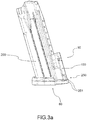
Figures 3a and3b are respectively front and bottom views of an electronic device having a charging battery according to a preferred embodiment; - -
Figures 4a and 4b are respectively top and side views of a firearm base according to a preferred embodiment; - -
Figure 5 is a perspective view of the firearm element housable inside a gun according to a preferred embodiment. - With reference to the accompanying figures, the
reference number 1 indicates an electronic device for afirearm 50 in its entirety. - According to an inventive embodiment, said
firearm 50 is a handgun. - Preferably, the electronic device - 1 comprises two main portions suitable to interact, operatively connected, to one another.
- In fact, according to the invention, the
electronic device 1 comprises afirearm element 10, configured to detect and/or manage one or more events occurring to thefirearm 50, including an event of a shot fired. - In particular, the
firearm element 10 comprises detection and processing means suitable to detect and process the firearm information. In particular, the detection and processing means comprise a specific electronic and/or mechanical component (not described or shown) suitable to detect information related to the state of the firearm in order to then place it at the service of the shooter and users in general. In an embodiment, the detection and processing means are suitable to detect and process the information of round in barrel, weapon ready to fire, weapon pointed, or the like. Preferably, the detection and processing means are suitable, for example, to assess the intensity of the accelerations experienced by the firearm, identifying a state of shot fired, and thus creating a specific shot fired information. - In addition, the detection and processing means comprise a specific component, preferably electronic (also not described or represented) for processing the firearm information created, for example the above-mentioned information of shot fired, for example by storing it. In fact, preferably, the
firearm element 10, in particular in the detection and processing means, comprises memory means suitable to store the firearm information. - In addition, in a preferred embodiment, the
firearm element 10 also comprises verification means suitable to verify and distinguish the type of action experienced by the firearm, for example, by distinguishing the firing event with respect to a misfire event or the firearm falling to the ground. - In fact, in a preferred embodiment, the
firearm element 10 is suitable to be operatively connected with a mobile phone or smartphone, with which is respectively coupled, for example by "pairing". Preferably, thefirearm element 10 is suitable to communicate with the mobile phone or smartphone with which it is coupled to mutually exchange information. - According to the invention, the
firearm element 10 is housable in a housing 510 in thegrip 55 of thefirearm 50. - In particular, in fact, the
firearm 50 includes a stock 51 and abarrel 52 that extends along a firing axis X-X. The stock 51 comprises agrip 55 suitable to be gripped by the shooter. Preferably, thegrip 55 extends along a grip axis Y-Y identifying abottom 555 at its end opposite with respect to thebarrel 52. In addition, thegrip 55 has adistal portion 551 in the proximity of the trigger of the firearm and aproximal portion 552 next to the palm of the shooter's hand when holding the gun. - In a preferred embodiment, wherein the
firearm 50 is a gun, thegrip 55 comprises at least onegrip plate 558 mountable on the gun to delimit and protect the housing recess 510 and removable from thegun 1 to allow access to the housing recess 510 and thus, for example, allow the insertion of thefirearm element 10 in the gun. - Preferably, the
grip plate 558 is snap-mountable on thegrip 55. Preferably, thegrip plate 558 is mountable with an action in the direction of the can be mounted with the direction of the firing axis X-X or the grip axis Y-Y. - In a preferred embodiment, inside the
grip 55 is housed themagazine 559 of the firearm, preferably, in a specially shaped magazine housing 559'. In the embodiment wherein thefirearm 50 is a gun, the magazine housing 559' extends along the grip axis Y-Y. - According to the invention, the
firearm element 10 comprises apower supply battery 100, specifically for its power. - In a preferred embodiment, the
power supply battery 100 is of the type comprising lithium ions. - According to the invention, the
firearm element 10 comprises afirearm interface port 150 for access to saidpower supply battery 100. - According to a preferred embodiment, said
firearm interface port 150 is formed on thebottom 555. Preferably, thefirearm interface port 150 is flush with thebottom surface 555. - According to the invention, the
firearm interface port 150 comprises at least onefirearm pin 151, preferably comprises twofire pins 151 placed at a distance from each other. - According to the invention, the
electronic device 1 also includes abase element 20 suitable to be operatively connected with thefirearm element 10. - According to the invention, the
base element 20 comprises abase interface port 250 suitable to engage with thefirearm interface port 150. - According to the invention, in the reciprocal engagement between the
firearm element 10 and thebase element 20 through thefirearm interface port 150 andbase interface port 250, thebase element 20 is suitable to electrically recharge thepower supply battery 100. - According to the invention, the
base interface port 250 comprises at least onebase pin 251; in further embodiments, this comprises twobase pins 251. In other words, the number of pins of thebase interface port 250 is the same as the number of pins of thefirearm interface port 251; i.e., the respective pins of thefirearm element 10 and thebase element 20 fit together for the mutual electrical interaction. - Basically, the
firearm interface port 150 and thebase interface port 250 are suitable to work together according to the plug-socket principle. - The mutual engagement between
firearm pin 151 andbase pin 251 is mechanical. For example with a possible shape coupling thanks to the fact that one of the two is concave, while the other is convex. - According to the invention, the
firearm pin 151 is flat or convex in such a way so as not to accumulate dirt inside it, while thebase pin 251 has a substantially complementary shape. For example, conical, truncated-conical or spherical couplings between two reciprocal pins are foreseeable. - According to the invention the
base pin 251 further comprises elastic elements suitable to allow a recovery of the construction tolerances and therefore to allow correct alignment between the firearm and base pins. - In a preferred embodiment, the
firearm interface port 150 is also suitable to allow the transmission of data. In other words, in the operating engagement betweenfirearm element 10 andbase element 20, thebase element 20 is suitable to access to data and information collected by thefirearm element 10. - Preferably the transmission of data and information through the
firearm interface port 150 is bi-directional also allowing the uploading of data and information into thefirearm element 10, such as, for example, the uploading and/or updating of the internal software. - In other words, the
firearm interface port 150 andbase interface port 250 are mutually positioned relative to one another in such a way that the respective pins fit together and allow both the mutual electrical interaction of recharging and the interaction of data transmission. - According to a preferred embodiment, the
base element 20 is engageable to thegrip 55, in order to satisfy the characteristics of theelectronic device 1 described above. - According to the invention, the
base element 20 includes amain port 210 electrically connected with thebase interface port 250. - According to the invention, said
main port 210 is suitable to be operatively connected to a power source, to provide electricity to thebase element 20, and therefore when this is engaged with thefirearm element 10 to allow recharging thepower supply battery 100. - Preferably, according to a preferred embodiment, the
main port 210 is also suitable to allow the transmission of data and information collected by thefirearm element 10. In other words, data transmission is also allowed through themain port 210. - According to a preferred embodiment, the
main port 210 is of the USB type. - In an embodiment, the
base element 20 comprises a chargingbattery 200 suitable to permit recharging of thepower supply battery 100 in a configuration having thefirearm element 10 andbase element 20 operatively connected. - In other words, thanks to the charging
battery 200, thebase element 20 is suitable to recharge thepower battery 100 without requiring that thebase element 20 be connected to a source of electricity. - Preferably, the charging
battery 200 is rechargeable through themain port 210. - In a preferred embodiment, the charging
battery 200 is of the type comprising lithium ions. - Preferably, the charging
battery 200 is suitable to be housed in the magazine housing 559' of thefirearm 50. In fact, in a preferred embodiment, the chargingbattery 200 has substantially the same shape as themagazine 559. - In a further embodiment, the charging
battery 200 is contained in a magazine and thebase element 20 is constituted, accordingly, comprising said magazine. In other words, thebase element 20 comprises a magazine that, for a portion, is suitable to contain, inside it, a plurality of rounds while the remaining area contains a chargingbattery 200. - According to a preferred embodiment, the
base element 20 is comprised in afirearm base 60, in such a way that thefirearm 50 is insertable onto saidfirearm base 60. In other words, thebase element 20 is housable in afirearm base 60 specifically suitable to engage thefirearm 50, preferably thegrip 55. In yet further other words, thefirearm base 60 is suitable to receive thefirearm 50, in particular itsgrip 55, to allow the mutual engagement of thebase element 20 and thefirearm element 10 for charging of the latter or for the use of the information collected in it. - Preferably, the
firearm base 60 is therefore specifically suitable to support thefirearm 50, for example when it is not used. - Thus, in a preferred embodiment, the surfaces of the firearm base. 60 contain the
base interface port 250 and/or themain port 210. - According to a preferred embodiment, the
gun 50, slid out of themagazine 559, is suitable to be accomodated in thefirearm base 60, in such a way that the chargingbattery 200 sits in the magazine housing. - In a preferred embodiment, the charging
battery 200 is an emergency battery suitable to cooperate with thebase element 20 for recharging thepower supply battery 100. - In addition, according to further preferred embodiments, the
base element 20 comprises alerting elements, such as a luminous element or an LED; these alerting elements are suitable to indicate the state of charge of thepower supply battery 100. In other words, when thebase element 20 is engaged with thefirearm element 10, the first is suitable to indicate whether, and when, thepower supply battery 100 is charged, for example, allowing the user to stop the charging operation. - Innovatively, the electronic device of this invention solves the typical problems of the known art, by comprising a firearm element, housable in the firearm and containing a power supply battery and a base element housable in a firearm base, suitable to be coupled and operatively connected with each other to recharge said power supply battery.
- Advantageously, the firearm element and base element are provided with special interface ports in such a way as to ensure said precise coupling.
- Moreover, advantageously, the charging operation is simple to perform and, therefore, easily repeatable.
- A further advantage of the electronic device resides in the fact that the power supply battery is chargeable only through the base element, and not by means of a generic connection to the electric mains.
- Advantageously, the firearm element and base element allow mutual bi-directional data transmission.
- A further advantage of the electronic device resides, therefore, in the fact that access to the information collected by the firearm element occurs only through the base element.
- In addition, advantageously, in the firearm there is no direct access socket that can be accessed to recharge and extract the information collected by the firearm element.
- A further advantage, therefore, is that of having a secure firearm.
- Advantageously, the only access to the firearm element is through firearm interface port, for example through the respective pins.
- Moreover, advantageously, since there are no sockets formed on the firearm, there is no risk of dirt collecting inside them and, in fact, according to the invention the access port is flush on the firearm or convex.
- A further advantageous aspect lies in the possibility that the main port is a USB type port.
- A still further advantageous aspect resides in the fact that all the above-mentioned advantages are applicable to a gun; in fact, the lack of invasiveness of the electric device of this invention makes it applicable to a gun, in other words to a small firearm. Advantageously, the structure of the firearm is not significantly disturbed, except for the specific housing for containing the firearm element.
- Moreover, advantageously, embodiments are foreseeable wherein the electronic device, in particular the base element, comprises a specific charging battery, allowing charging operations that do not require the access to the electric mains.
- Advantageously, the electronic device is rechargable even in mobility, for example by replacing the magazine and coupling the firearm with the firearm base.
- Furthermore, advantageously, when the firearm is not being used, it is accommodated on the specific firearm base to recharge the power supply battery. So, for example, it is foreseeable that, at the end of a shift, the shooter, for example a policeman, will put his firearm on the firearm base.
- Advantageously, an event is foreseeable in which, with the firearm put back on the firearm base, the information collected by the firearm element is downloaded in its entirety.
- Advantageously, the firearm element is suitable to operate in a plurality of detection, processing and storage modes of a multiplicity of firearm states.
- Moreover, advantageously, the firearm element is rechargeable through the charging battery even when placed in a safe or similar, in other words when the firearm is placed in a secure housing location, for example in a specific armoury.
- It is clear that one skilled in the art, in order to meet contingent needs, may make changes to the firearm described above, all contained within the scope of protection defined by the following claims.
Claims (9)
- Electronic device (1) for a firearm (50) having a grip (55) comprising:a) a firearm element (10), configured to detect and/or manage one or more events occurring to the firearm (50), including an event of a shot fired, housable in a housing (550) in the grip (55) of the firearm (50), wherein the firearm element (10) comprises a power supply battery (100) and comprises a firearm interface port (150) for access to said power supply battery (100), wherein the firearm interface port (150) comprises at least one firearm pin (151) flat or convex in such a way that is flush or convex with respect to the firearm (50), when the firearm element (10) is housed in the grip (55) of the firearm (50);b) a base element (20) engageable to the grip (55), for example housed in a firearm base (60), comprising a base interface port (250) that comprises at least one base pin (251), wherein the base pin (251) has a substantially complementary shape of the respective firearm pin (151), wherein the base element (20) comprises a main port (210) electrically connected with the base interface port (250), wherein the main port (210) is configured to be operatively connected to a source of electricity, to provide electrical power to the base element (20), wherein the base pin (251) further comprises elastic elements suitable to allow correct alignment between the at least one firearm pin (151) and the at least one base pin (251);wherein, in the reciprocal engagement between the firearm element (10) and the base element (20) through the at least one firearm pin (151) and the respective at least base pin (251), the base element (20) is configured to electrically recharge the power supply battery (100).
- Electronic device (1) according to claim 1, wherein the grip (55) has a bottom (555), wherein the firearm interface port (150) is on said bottom (555).
- Electronic device (1) according to any of the preceding claims, wherein the firearm interface port (150) is also suitable to enable two-way data transmission, so that in the operating engagement between the firearm element (10) and base element (20), the base element (20) is suitable to access data and information collected by the firearm element (10) or to supply information and data to the firearm element (10).
- Electronic device (1) according to claim 3, wherein the main port (210) is suitable to allow the electricity power supply of the power supply battery (100) and the use of the data and information collected from the firearm element (10), preferably the main port (210) is of the USB (Universal Serial Bus) type.
- Electronic device (1) according to any of the preceding claims, wherein the base element (20) comprises a charging battery (200) suitable to permit recharging of the power supply battery (100) in a configuration having the firearm element (10) and base element (20) operatively connected.
- Electronic device (1) according to claim 5, wherein the charging battery (200) is suitable to be housed in a magazine housing (558) of the firearm (50).
- Electronic device (1) according to any of the preceding claims, wherein the base element (20) is comprised in a firearm base (60), in such a way that the firearm (50) is insertable onto said firearm base (60).
- Electronic device (1) according to any of the preceding claims, wherein the firearm (50) to which it is applicable, is a handgun.
- Handgun comprising:a grip (55); anda firearm element (10), configured to detect and/or manage one or more events occurring to the handgun (50), including an event of a shot fired, housed in a housing (550) in the grip (55) of the handgun (50),wherein the firearm element (10) comprises a power supply battery (100) and comprises a firearm interface port (150) for access to said power supply battery (100), wherein the firearm interface port (150) comprises at least one firearm pin (151) flat or convex in such a way that is flush or convex with respect to the handgun (50);wherein the firearm element is configured to be engaged to a base element (20), housed in a firearm base (60), comprising a base interface port (250) that comprises at least one base pin (251),wherein the base pin (251) has a substantially complementary shape of the respective firearm pin wherein the base element (20) comprises a main port (210) electrically connected with the base interface port (250), wherein the main port (210) is configured to be operatively connected to a source of electricity, to provide electrical power to the base element (20), wherein the base pin (251) further comprises elastic elements suitable to allow correct alignment between the at least one firearm pin (151) and the at least one base pin (251);wherein, in the reciprocal engagement between the firearm element (10) and the base element (20) through the at least one firearm pin (151) and the respective at least base pin (251), the power supply battery (100) is configured to be electrically recharged by the base element (20).
Applications Claiming Priority (2)
| Application Number | Priority Date | Filing Date | Title |
|---|---|---|---|
| ITBS20150084 | 2015-05-14 | ||
| PCT/IB2016/051789 WO2016181236A1 (en) | 2015-05-14 | 2016-03-30 | Electronic device for a firearm |
Publications (2)
| Publication Number | Publication Date |
|---|---|
| EP3295114A1 EP3295114A1 (en) | 2018-03-21 |
| EP3295114B1 true EP3295114B1 (en) | 2021-12-15 |
Family
ID=54011772
Family Applications (1)
| Application Number | Title | Priority Date | Filing Date |
|---|---|---|---|
| EP16720898.2A Active EP3295114B1 (en) | 2015-05-14 | 2016-03-30 | Electronic device for a firearm |
Country Status (3)
| Country | Link |
|---|---|
| US (1) | US10295294B2 (en) |
| EP (1) | EP3295114B1 (en) |
| WO (1) | WO2016181236A1 (en) |
Families Citing this family (4)
| Publication number | Priority date | Publication date | Assignee | Title |
|---|---|---|---|---|
| AT518391B1 (en) * | 2017-02-14 | 2017-10-15 | Bubits Wilhelm | Magazine of a pistol for cartridges with sleeve edge and pistol with such |
| USD894314S1 (en) * | 2018-01-18 | 2020-08-25 | Paul T. Noonan | Frame |
| USD894315S1 (en) * | 2018-01-18 | 2020-08-25 | Paul T. Noonan | Frame |
| US12196519B1 (en) | 2022-02-19 | 2025-01-14 | James E. Stilwell, III | Remote light activation from side arm |
Family Cites Families (9)
| Publication number | Priority date | Publication date | Assignee | Title |
|---|---|---|---|---|
| FR2654557B1 (en) * | 1989-11-10 | 1992-01-17 | Labinal | MALE ELECTRIC CONTACT MEMBER AND CORRESPONDING ELECTRICAL CONNECTION BOX. |
| US5179235A (en) * | 1991-09-10 | 1993-01-12 | Toole Ronald L | Pistol sighting device |
| US5704153A (en) * | 1996-07-23 | 1998-01-06 | Colt's Manufacturing Company, Inc. | Firearm battery and control module |
| US6321478B1 (en) * | 1998-12-04 | 2001-11-27 | Smith & Wesson Corp. | Firearm having an intelligent controller |
| US6267602B1 (en) * | 1999-11-02 | 2001-07-31 | Kinetic Group L.L.C. | Detachable power supply apparatus |
| US6563940B2 (en) | 2001-05-16 | 2003-05-13 | New Jersey Institute Of Technology | Unauthorized user prevention device and method |
| US8261666B2 (en) * | 2008-10-26 | 2012-09-11 | Rakesh Garg | Charging holder for a non-lethal projectile |
| EP2354748A1 (en) * | 2010-01-29 | 2011-08-10 | Antonio Manuel Guerra Navas | Control system for firearms and a control device for firearms |
| US10088269B2 (en) * | 2016-01-15 | 2018-10-02 | Sig Sauer, Inc. | Firearm with integrated power source |
-
2016
- 2016-03-30 US US15/573,145 patent/US10295294B2/en active Active
- 2016-03-30 EP EP16720898.2A patent/EP3295114B1/en active Active
- 2016-03-30 WO PCT/IB2016/051789 patent/WO2016181236A1/en not_active Ceased
Also Published As
| Publication number | Publication date |
|---|---|
| EP3295114A1 (en) | 2018-03-21 |
| WO2016181236A1 (en) | 2016-11-17 |
| US10295294B2 (en) | 2019-05-21 |
| US20180120047A1 (en) | 2018-05-03 |
Similar Documents
| Publication | Publication Date | Title |
|---|---|---|
| AU2019200485B2 (en) | A network of intercommunicating battlefield devices | |
| US10477618B2 (en) | Networked battle system or firearm | |
| US10295294B2 (en) | Electronic device for a firearm | |
| US9472971B2 (en) | Wireless inductive charging of weapon system energy source | |
| US20160377383A1 (en) | Networked battle system or firearm | |
| US8402683B2 (en) | Rifle accessory rail, communication, and power transfer system-battery pack | |
| CA2908702C (en) | Wireless inductive charging of weapon system energy source | |
| WO2007000055A1 (en) | Contactless battery charging apparel | |
| US20110099872A1 (en) | End stock magazine storage device | |
| WO2022225754A2 (en) | Electrical power source for a firearm | |
| US20200278174A1 (en) | Tactical vest system and method for powering an electronic device on a rifle | |
| EP2746713B1 (en) | Weapon firing simulator | |
| US9080835B1 (en) | Tactical attachment system for firearms | |
| EP3295112B1 (en) | Gun comprising an electronic device | |
| US9080833B1 (en) | Tactical attachment system for firearms | |
| US20230280134A1 (en) | Firearm Training Apparatuses, Systems and Methods of Using | |
| US20190372066A1 (en) | Battery bays and systems configured for different battery types | |
| EP2354748A1 (en) | Control system for firearms and a control device for firearms | |
| CN216448695U (en) | Positionable magazine and holster | |
| GB2637373A (en) | Firearm magazine and system for monitoring rounds |
Legal Events
| Date | Code | Title | Description |
|---|---|---|---|
| STAA | Information on the status of an ep patent application or granted ep patent |
Free format text: STATUS: THE INTERNATIONAL PUBLICATION HAS BEEN MADE |
|
| PUAI | Public reference made under article 153(3) epc to a published international application that has entered the european phase |
Free format text: ORIGINAL CODE: 0009012 |
|
| STAA | Information on the status of an ep patent application or granted ep patent |
Free format text: STATUS: REQUEST FOR EXAMINATION WAS MADE |
|
| 17P | Request for examination filed |
Effective date: 20170927 |
|
| AK | Designated contracting states |
Kind code of ref document: A1 Designated state(s): AL AT BE BG CH CY CZ DE DK EE ES FI FR GB GR HR HU IE IS IT LI LT LU LV MC MK MT NL NO PL PT RO RS SE SI SK SM TR |
|
| AX | Request for extension of the european patent |
Extension state: BA ME |
|
| DAV | Request for validation of the european patent (deleted) | ||
| DAX | Request for extension of the european patent (deleted) | ||
| GRAP | Despatch of communication of intention to grant a patent |
Free format text: ORIGINAL CODE: EPIDOSNIGR1 |
|
| STAA | Information on the status of an ep patent application or granted ep patent |
Free format text: STATUS: GRANT OF PATENT IS INTENDED |
|
| INTG | Intention to grant announced |
Effective date: 20210729 |
|
| GRAS | Grant fee paid |
Free format text: ORIGINAL CODE: EPIDOSNIGR3 |
|
| GRAA | (expected) grant |
Free format text: ORIGINAL CODE: 0009210 |
|
| STAA | Information on the status of an ep patent application or granted ep patent |
Free format text: STATUS: THE PATENT HAS BEEN GRANTED |
|
| AK | Designated contracting states |
Kind code of ref document: B1 Designated state(s): AL AT BE BG CH CY CZ DE DK EE ES FI FR GB GR HR HU IE IS IT LI LT LU LV MC MK MT NL NO PL PT RO RS SE SI SK SM TR |
|
| REG | Reference to a national code |
Ref country code: GB Ref legal event code: FG4D Ref country code: CH Ref legal event code: EP |
|
| REG | Reference to a national code |
Ref country code: DE Ref legal event code: R096 Ref document number: 602016067354 Country of ref document: DE |
|
| REG | Reference to a national code |
Ref country code: IE Ref legal event code: FG4D |
|
| REG | Reference to a national code |
Ref country code: AT Ref legal event code: REF Ref document number: 1455788 Country of ref document: AT Kind code of ref document: T Effective date: 20220115 |
|
| REG | Reference to a national code |
Ref country code: LT Ref legal event code: MG9D |
|
| REG | Reference to a national code |
Ref country code: NL Ref legal event code: MP Effective date: 20211215 |
|
| PG25 | Lapsed in a contracting state [announced via postgrant information from national office to epo] |
Ref country code: RS Free format text: LAPSE BECAUSE OF FAILURE TO SUBMIT A TRANSLATION OF THE DESCRIPTION OR TO PAY THE FEE WITHIN THE PRESCRIBED TIME-LIMIT Effective date: 20211215 Ref country code: LT Free format text: LAPSE BECAUSE OF FAILURE TO SUBMIT A TRANSLATION OF THE DESCRIPTION OR TO PAY THE FEE WITHIN THE PRESCRIBED TIME-LIMIT Effective date: 20211215 Ref country code: FI Free format text: LAPSE BECAUSE OF FAILURE TO SUBMIT A TRANSLATION OF THE DESCRIPTION OR TO PAY THE FEE WITHIN THE PRESCRIBED TIME-LIMIT Effective date: 20211215 Ref country code: BG Free format text: LAPSE BECAUSE OF FAILURE TO SUBMIT A TRANSLATION OF THE DESCRIPTION OR TO PAY THE FEE WITHIN THE PRESCRIBED TIME-LIMIT Effective date: 20220315 |
|
| REG | Reference to a national code |
Ref country code: AT Ref legal event code: MK05 Ref document number: 1455788 Country of ref document: AT Kind code of ref document: T Effective date: 20211215 |
|
| PG25 | Lapsed in a contracting state [announced via postgrant information from national office to epo] |
Ref country code: SE Free format text: LAPSE BECAUSE OF FAILURE TO SUBMIT A TRANSLATION OF THE DESCRIPTION OR TO PAY THE FEE WITHIN THE PRESCRIBED TIME-LIMIT Effective date: 20211215 Ref country code: NO Free format text: LAPSE BECAUSE OF FAILURE TO SUBMIT A TRANSLATION OF THE DESCRIPTION OR TO PAY THE FEE WITHIN THE PRESCRIBED TIME-LIMIT Effective date: 20220315 Ref country code: LV Free format text: LAPSE BECAUSE OF FAILURE TO SUBMIT A TRANSLATION OF THE DESCRIPTION OR TO PAY THE FEE WITHIN THE PRESCRIBED TIME-LIMIT Effective date: 20211215 Ref country code: HR Free format text: LAPSE BECAUSE OF FAILURE TO SUBMIT A TRANSLATION OF THE DESCRIPTION OR TO PAY THE FEE WITHIN THE PRESCRIBED TIME-LIMIT Effective date: 20211215 Ref country code: GR Free format text: LAPSE BECAUSE OF FAILURE TO SUBMIT A TRANSLATION OF THE DESCRIPTION OR TO PAY THE FEE WITHIN THE PRESCRIBED TIME-LIMIT Effective date: 20220316 |
|
| PGFP | Annual fee paid to national office [announced via postgrant information from national office to epo] |
Ref country code: IT Payment date: 20220304 Year of fee payment: 7 |
|
| PG25 | Lapsed in a contracting state [announced via postgrant information from national office to epo] |
Ref country code: NL Free format text: LAPSE BECAUSE OF FAILURE TO SUBMIT A TRANSLATION OF THE DESCRIPTION OR TO PAY THE FEE WITHIN THE PRESCRIBED TIME-LIMIT Effective date: 20211215 |
|
| PG25 | Lapsed in a contracting state [announced via postgrant information from national office to epo] |
Ref country code: SM Free format text: LAPSE BECAUSE OF FAILURE TO SUBMIT A TRANSLATION OF THE DESCRIPTION OR TO PAY THE FEE WITHIN THE PRESCRIBED TIME-LIMIT Effective date: 20211215 Ref country code: SK Free format text: LAPSE BECAUSE OF FAILURE TO SUBMIT A TRANSLATION OF THE DESCRIPTION OR TO PAY THE FEE WITHIN THE PRESCRIBED TIME-LIMIT Effective date: 20211215 Ref country code: RO Free format text: LAPSE BECAUSE OF FAILURE TO SUBMIT A TRANSLATION OF THE DESCRIPTION OR TO PAY THE FEE WITHIN THE PRESCRIBED TIME-LIMIT Effective date: 20211215 Ref country code: PT Free format text: LAPSE BECAUSE OF FAILURE TO SUBMIT A TRANSLATION OF THE DESCRIPTION OR TO PAY THE FEE WITHIN THE PRESCRIBED TIME-LIMIT Effective date: 20220418 Ref country code: ES Free format text: LAPSE BECAUSE OF FAILURE TO SUBMIT A TRANSLATION OF THE DESCRIPTION OR TO PAY THE FEE WITHIN THE PRESCRIBED TIME-LIMIT Effective date: 20211215 Ref country code: EE Free format text: LAPSE BECAUSE OF FAILURE TO SUBMIT A TRANSLATION OF THE DESCRIPTION OR TO PAY THE FEE WITHIN THE PRESCRIBED TIME-LIMIT Effective date: 20211215 Ref country code: CZ Free format text: LAPSE BECAUSE OF FAILURE TO SUBMIT A TRANSLATION OF THE DESCRIPTION OR TO PAY THE FEE WITHIN THE PRESCRIBED TIME-LIMIT Effective date: 20211215 |
|
| PG25 | Lapsed in a contracting state [announced via postgrant information from national office to epo] |
Ref country code: PL Free format text: LAPSE BECAUSE OF FAILURE TO SUBMIT A TRANSLATION OF THE DESCRIPTION OR TO PAY THE FEE WITHIN THE PRESCRIBED TIME-LIMIT Effective date: 20211215 Ref country code: AT Free format text: LAPSE BECAUSE OF FAILURE TO SUBMIT A TRANSLATION OF THE DESCRIPTION OR TO PAY THE FEE WITHIN THE PRESCRIBED TIME-LIMIT Effective date: 20211215 |
|
| REG | Reference to a national code |
Ref country code: DE Ref legal event code: R097 Ref document number: 602016067354 Country of ref document: DE |
|
| PG25 | Lapsed in a contracting state [announced via postgrant information from national office to epo] |
Ref country code: IS Free format text: LAPSE BECAUSE OF FAILURE TO SUBMIT A TRANSLATION OF THE DESCRIPTION OR TO PAY THE FEE WITHIN THE PRESCRIBED TIME-LIMIT Effective date: 20220415 |
|
| PLBE | No opposition filed within time limit |
Free format text: ORIGINAL CODE: 0009261 |
|
| STAA | Information on the status of an ep patent application or granted ep patent |
Free format text: STATUS: NO OPPOSITION FILED WITHIN TIME LIMIT |
|
| PG25 | Lapsed in a contracting state [announced via postgrant information from national office to epo] |
Ref country code: MC Free format text: LAPSE BECAUSE OF FAILURE TO SUBMIT A TRANSLATION OF THE DESCRIPTION OR TO PAY THE FEE WITHIN THE PRESCRIBED TIME-LIMIT Effective date: 20211215 Ref country code: DK Free format text: LAPSE BECAUSE OF FAILURE TO SUBMIT A TRANSLATION OF THE DESCRIPTION OR TO PAY THE FEE WITHIN THE PRESCRIBED TIME-LIMIT Effective date: 20211215 Ref country code: AL Free format text: LAPSE BECAUSE OF FAILURE TO SUBMIT A TRANSLATION OF THE DESCRIPTION OR TO PAY THE FEE WITHIN THE PRESCRIBED TIME-LIMIT Effective date: 20211215 |
|
| REG | Reference to a national code |
Ref country code: CH Ref legal event code: PL |
|
| 26N | No opposition filed |
Effective date: 20220916 |
|
| GBPC | Gb: european patent ceased through non-payment of renewal fee |
Effective date: 20220330 |
|
| PG25 | Lapsed in a contracting state [announced via postgrant information from national office to epo] |
Ref country code: SI Free format text: LAPSE BECAUSE OF FAILURE TO SUBMIT A TRANSLATION OF THE DESCRIPTION OR TO PAY THE FEE WITHIN THE PRESCRIBED TIME-LIMIT Effective date: 20211215 |
|
| PG25 | Lapsed in a contracting state [announced via postgrant information from national office to epo] |
Ref country code: LU Free format text: LAPSE BECAUSE OF NON-PAYMENT OF DUE FEES Effective date: 20220330 Ref country code: LI Free format text: LAPSE BECAUSE OF NON-PAYMENT OF DUE FEES Effective date: 20220331 Ref country code: IE Free format text: LAPSE BECAUSE OF NON-PAYMENT OF DUE FEES Effective date: 20220330 Ref country code: GB Free format text: LAPSE BECAUSE OF NON-PAYMENT OF DUE FEES Effective date: 20220330 Ref country code: FR Free format text: LAPSE BECAUSE OF NON-PAYMENT OF DUE FEES Effective date: 20220331 Ref country code: CH Free format text: LAPSE BECAUSE OF NON-PAYMENT OF DUE FEES Effective date: 20220331 |
|
| P01 | Opt-out of the competence of the unified patent court (upc) registered |
Effective date: 20230522 |
|
| PG25 | Lapsed in a contracting state [announced via postgrant information from national office to epo] |
Ref country code: HU Free format text: LAPSE BECAUSE OF FAILURE TO SUBMIT A TRANSLATION OF THE DESCRIPTION OR TO PAY THE FEE WITHIN THE PRESCRIBED TIME-LIMIT; INVALID AB INITIO Effective date: 20160330 |
|
| PG25 | Lapsed in a contracting state [announced via postgrant information from national office to epo] |
Ref country code: MK Free format text: LAPSE BECAUSE OF FAILURE TO SUBMIT A TRANSLATION OF THE DESCRIPTION OR TO PAY THE FEE WITHIN THE PRESCRIBED TIME-LIMIT Effective date: 20211215 Ref country code: IT Free format text: LAPSE BECAUSE OF NON-PAYMENT OF DUE FEES Effective date: 20230330 Ref country code: CY Free format text: LAPSE BECAUSE OF FAILURE TO SUBMIT A TRANSLATION OF THE DESCRIPTION OR TO PAY THE FEE WITHIN THE PRESCRIBED TIME-LIMIT Effective date: 20211215 |
|
| PG25 | Lapsed in a contracting state [announced via postgrant information from national office to epo] |
Ref country code: MT Free format text: LAPSE BECAUSE OF FAILURE TO SUBMIT A TRANSLATION OF THE DESCRIPTION OR TO PAY THE FEE WITHIN THE PRESCRIBED TIME-LIMIT Effective date: 20211215 |
|
| PG25 | Lapsed in a contracting state [announced via postgrant information from national office to epo] |
Ref country code: TR Free format text: LAPSE BECAUSE OF FAILURE TO SUBMIT A TRANSLATION OF THE DESCRIPTION OR TO PAY THE FEE WITHIN THE PRESCRIBED TIME-LIMIT Effective date: 20211215 |
|
| PGFP | Annual fee paid to national office [announced via postgrant information from national office to epo] |
Ref country code: DE Payment date: 20260325 Year of fee payment: 11 |
|
| PGFP | Annual fee paid to national office [announced via postgrant information from national office to epo] |
Ref country code: BE Payment date: 20260319 Year of fee payment: 11 |