EP3295112B1 - Gun comprising an electronic device - Google Patents
Gun comprising an electronic device Download PDFInfo
- Publication number
- EP3295112B1 EP3295112B1 EP16720897.4A EP16720897A EP3295112B1 EP 3295112 B1 EP3295112 B1 EP 3295112B1 EP 16720897 A EP16720897 A EP 16720897A EP 3295112 B1 EP3295112 B1 EP 3295112B1
- Authority
- EP
- European Patent Office
- Prior art keywords
- gun
- hammer
- battery
- holster
- electronic device
- Prior art date
- Legal status (The legal status is an assumption and is not a legal conclusion. Google has not performed a legal analysis and makes no representation as to the accuracy of the status listed.)
- Active
Links
Images



Classifications
-
- F—MECHANICAL ENGINEERING; LIGHTING; HEATING; WEAPONS; BLASTING
- F41—WEAPONS
- F41A—FUNCTIONAL FEATURES OR DETAILS COMMON TO BOTH SMALLARMS AND ORDNANCE, e.g. CANNONS; MOUNTINGS FOR SMALLARMS OR ORDNANCE
- F41A19/00—Firing or trigger mechanisms; Cocking mechanisms
- F41A19/06—Mechanical firing mechanisms, e.g. counterrecoil firing, recoil actuated firing mechanisms
- F41A19/42—Mechanical firing mechanisms, e.g. counterrecoil firing, recoil actuated firing mechanisms having at least one hammer
- F41A19/43—Mechanical firing mechanisms, e.g. counterrecoil firing, recoil actuated firing mechanisms having at least one hammer in bolt-action guns
- F41A19/47—Cocking mechanisms
-
- F—MECHANICAL ENGINEERING; LIGHTING; HEATING; WEAPONS; BLASTING
- F41—WEAPONS
- F41A—FUNCTIONAL FEATURES OR DETAILS COMMON TO BOTH SMALLARMS AND ORDNANCE, e.g. CANNONS; MOUNTINGS FOR SMALLARMS OR ORDNANCE
- F41A35/00—Accessories or details not otherwise provided for
-
- F—MECHANICAL ENGINEERING; LIGHTING; HEATING; WEAPONS; BLASTING
- F41—WEAPONS
- F41C—SMALLARMS, e.g. PISTOLS, RIFLES; ACCESSORIES THEREFOR
- F41C33/00—Means for wearing or carrying smallarms
- F41C33/02—Holsters, i.e. cases for pistols having means for being carried or worn, e.g. at the belt or under the arm
-
- F—MECHANICAL ENGINEERING; LIGHTING; HEATING; WEAPONS; BLASTING
- F41—WEAPONS
- F41C—SMALLARMS, e.g. PISTOLS, RIFLES; ACCESSORIES THEREFOR
- F41C33/00—Means for wearing or carrying smallarms
- F41C33/02—Holsters, i.e. cases for pistols having means for being carried or worn, e.g. at the belt or under the arm
- F41C33/029—Holsters, i.e. cases for pistols having means for being carried or worn, e.g. at the belt or under the arm combined with electronic devices, e.g. GPS
-
- F—MECHANICAL ENGINEERING; LIGHTING; HEATING; WEAPONS; BLASTING
- F41—WEAPONS
- F41A—FUNCTIONAL FEATURES OR DETAILS COMMON TO BOTH SMALLARMS AND ORDNANCE, e.g. CANNONS; MOUNTINGS FOR SMALLARMS OR ORDNANCE
- F41A19/00—Firing or trigger mechanisms; Cocking mechanisms
- F41A19/01—Counting means indicating the number of shots fired
Definitions
- This invention relates to a gun comprising an electronic device suitable to be activated only when certain predefined events occur to the gun. Furthermore, this invention also covers a firearm kit comprising the gun and its holster. In addition, this invention also covers a holster suitable to accommodate said gun.
- firearms comprising electronic devices of various types, for example suitable to locate the firearm detect a shot fired, count the nurrber of shots fired or the like.
- the purpose of this invention is to provide a gun comprising an electronic device suitable to detect and/or process information relating to situations or events that have occurred to the gun, effectively and for a long period of time.
- FIG. 1 is a perspective view of a firearm in particular a gun, comprising an electronic device inside it, according to a preferred embodiment
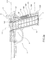
- FIGS. 2a and 2b are two cross-sect i onal views of the stock of the gun of Figure 1 , respectively, with hammer lowered and hammer cocked;
- the reference number 1 indicates a gun in its entirety.
- the gun 1 comprises a stock 3 and a barrel 2, which extends along a firing axis X-X, comprising moving parts 91, such as a slide.
- the firing axis X-X axis is the axis identifying the direction of the shot.
- the gun 1 comprises, among other components, a firing mechanism 9, having a trigger 4 that, in the action of firing, is pressed by the shooter, and having a hammer 5 that is movable and changes position in such a way that it is suitable to strike the firing pin triggering the bullet and thus the shot, in the event of firing.
- the hammer 5 is suitable to be positioned, manually by the shooter or automatically by the firing mechanism 9, between a hammer cocked position and a hammer lowered position and vice versa.
- the stock 3 comprises a grip 31 having a distal portion 311 in the vicinity of the trigger 4 and a proximal portion 312 next to the palm of the shooter's hand when holding the gun.
- the grip 31 also identifies a bottom 3', as its final end; preferably, the magazine 8 of the gun 1 is inserted in the firearm through the bottom 3' of the grip 31.
- the grip 31 extends in height along a grip axis Y-Y.
- the gun 1 of this invention comprises an electronic device 10 suitable to detect and/or process information relating to situations occurring to the gun.
- the electronic device 10 comprises detection and processing means 100 suitable to detect and process the information.
- the detection and processing means 100 comprise a specific electronic and/or mechanical component (not described or shown) suitable to detect information related to the state of the gun in order to then place it at the service of the shooter and users in general.
- the detection and processing means 100 are suitable to detect and process an event or a change of state undergone by the firearm, for example, the information of round in barrel, weapon ready to fire, weapon pointed, or the like.
- the detection and processing means 100 are suitable to assess the intensity and/or direction of the accelerations experienced by the gun 1, identifying a state, or an event, of shot fired, and possibly creating a specific "shot fired information".
- the detection and processing means 100 comprise a specific component, preferably electronic (also not described or represented) for processing the information, for example the above-mentioned information of shot fired, for example for its storage and/or for its transmission.
- the detection and processing means 100 comprise memory means suitable to store the information.
- the detection and processing means 100 comprise transmission means suitable to send the information to a receiving device.
- the electronic device 10 is suitable to be operatively connected with a mobile phone or smartphone, with which is respectively coupled, for example by "pairing".
- the electronic device 10 is suitable to communicate with the mobile phone or smartphone with which is coupled to mutually exchange information.
- the detection and processing means 100 comprise means of verification suitable to check and distinguish the action undergone by the gun at the moment of the firing event compared to other actions thereon, such as a falling event.
- the electronic device 100 also comprises a battery 200 for the power supply of the detection and processing means 100.
- the battery 200 is of the type comprising lithium ions.
- said battery 200 is rechargeable.
- the electronic device 10 also comprises activation means 300 suitable to activate the operation of powering the detection and processing means 100 by the battery 200.
- said activation means 300 are suitable to perform the activation of the power supply operation of the battery 200 only in correspondence of a predefined event.
- the battery 200 does not power the detection and processing means 100, preserving the charge.
- the battery 200 and consequently the electronic device 10 are substantially in a dormant configuration, of "sleep", “stand by” or “suspension”, in which there is minimum consumption of energy, i.e., there is a minimum circulation of electricity inside it.
- the electronic device 10 in said dormant configuration, is substantially turned off, in other words there is no circulation of electricity inside it.
- the electronic device 10 is, thus, essentially in a power saving mode; in some embodiment variants, the electronic device 10 has minimal or no functionality, for example, the electronic device 10 maintains a "pairing" coupling with a mobile phone to which it is coupled, or again, the electronic device 10 has a timed functionality, in which, at predefined time intervals, it performs specific verification activities of its status and the status of the gun.
- said predefined event that involves the activation of the operations of the battery 200 through the activation means 300 is the extraction of the gun 1 from its respective holster (not shown in the accompanying figures).
- said predefined event that involves the activation of the operations of the battery 200 through the activation means 300 is the cocking of the hammer 5 of the gun 1, i.e., the change of position between the hammer lowered position and the hammer cocked position.
- said predefined event that involves the activation of the operations of the battery 200 through the activation means 300 is the cocking of the hammer 5 of the gun 1, regardless of whether or not it is removed from the respective holster.
- the detection and processing means 100 activated following the aforesaid events are suitable, in the first place, to consider, detect and process as information precisely the occurrence of such events, for example by sending or storing the information.
- the battery 200 is of small size, with respect to the currently known solutions and, in fact, the battery 200 is suitable to last more over time with respect to batteries of similar size and materials.
- the battery 200 and the activation means 300 are housed in the grip 31.
- the battery 200 and the activation means 300 are housed close to its bottom 3', in its proximal portion 312.
- the battery 200 and the activation means 300 are located in an area of the gun 1 farther from the moving parts 91 of the gun 1 and from its firing mechanism 9.
- the electronic device 10 in its entirety is housed in the grip 31, close to its bottom 3', in its proximal portion 312.
- the aforesaid elements i.e., the battery 200 and the activation means 300, or the electronic device 10 in its entirety, are housed in a housing recess 310' specifically formed in the grip 31.
- the grip 31 comprises at least one grip plate 35; the grip plate 35 is mountable on the gun 1 to delimit and protect the housing recess 310' and removable from the gun 1 to allow access to the housing recess 310'.
- the grip plate 35 is snap-mountable on the grip 31.
- the grip plate 35 is mountable with an action in the direction of the can be mounted with the direction of the firing axis X-X or the grip axis Y-Y.
- the battery 200 and the activation means 300, or the electronic device 10, in its entirety are inserted in the gun 1, in particular in the housing recess 310', substantially in the direction of the firing axis X-X.
- the activation means 300 of the gun 1 are suitable to operate by detecting the occurrence of a predefined event.
- the activation means 300 comprise a holster switch element 310, suitable to detect the extraction of the gun from its holster so that, upon the extraction of the gun from the holster, the holster switch element 310 sends an activation signal to the battery 200.
- the holster switch element 310 is magnetically sensitive and detects a change of magnetic field that occurs at the time of the extraction of the pistol 1.
- the holster switch element 310 is housed on the firearm in a position close to the trigger, for example next to the slide 91 of the gun 1.
- the holster houses on it a holster sensor suitable to be operatively connected to the holster switch element 310.
- the holster sensor is made of a ferro-magnetic material suitable to stimulate the holster switch element 310 that, preferably, is composed of a magnetic switch with permanent magnet, and/or of a magnetically sensitive electrical circuit, for example due to the Hall effect.
- the activation means 300 comprise a hammer switch element 315 operationally connected to the hammer 5 in order to detect the change of position and send the activation signal to the battery 200.
- the hammer 5 comprises a command portion 51 suitable to be moved by the shooter to move the hammer 5 from the hammer lowered position to that of hammer cocked and vice versa.
- the hammer 5 comprises a hammer rod 52 that extends inside the stock 3 between a command end 521 connected to the command portion 51 and a switch end 522 operatively connected to the hammer switch element 315.
- the hammer rod 52 is hinged with its command end 521 to the command portion 51.
- the command portion 51 is also moved by the firing mechanism of the gun itself.
- the hammer rod 52 has an elongated shape, preferably, in a manner parallel to the grip axis Y-Y.
- the gun 1 has a rod housing 52'.
- a movement of the command portion 51 corresponds a change of position of the switch end 522 detected by the hammer switch element 315 that sends the activation signal to the battery 200.
- the switch end 522 comprises a magnetically sensitive element 525 operationally connected to the hammer switch element 315, in its turn magnetically sensitive.
- the hammer switch element 315 is suitable to detect the magnetic field variation due to the change of position of the switch end 522, and thus of the magnetically sensitive element 525.
- the magnetically sensitive element 525 comprises a core made of ferromagnetic material, preferably comprising an element made of a permanently magnetic material.
- said core is also housed in a casing of a magnetically insulating, or non-magnetic, material.
- the switch end 522 comprises a command element suitable to physically engage the hammer switch element 315 so that, when pressed, it sends the activation signal to the battery 200.
- the hammer 5 further comprises an elastic element 55 suitable to perform an action on the hammer rod 52 to move the command portion 51 from the hammer cocked position to the hammer lowered position, thus resulting in the shot.
- the elastic element 55 is a helical spring 55' that extends around the hammer rod 52.
- the elastic element 55 is housed in the rod housing 52'.
- the hammer 5 comprises a support and guidance device 56 suitable to keep the hammer rod 52 in a predefined axial position.
- the support and guidance device 56 is placed inside the rod housing 52' near the switch end 522.
- the support and guidance device 56 has substantially a ring shape and the switch end 522 is suitable to slide inside said ring.
- a support and guidance device 56 is suitable to act as an abutment to the elastic element 55.
- this invention also covers a firearm kit comprising a gun 1 according to the above description and a holster specially shaped to house said gun 1, in such a way that the gun 1 and the holster are operationally connected to each other.
- the gun 1 is suitable to detect its in-holster state its extraction from it.
- the gun of this invention solves the typical problems of the known art, comprising an electronic device that does not require, unlike those of the prior art, large quantities of electricity to function, being suitable to be activated only upon the occurrence of a predefined event.
- the gun comprises an electronic device that normally remains in a dormant configuration, in which it consumes a minimal or zero amount of energy, while it is activated only upon the occurrence of predefined events.
- the electronic device is powered if the gun is extracted from the holster and/or if the hammer is placed in a hammer cocked position.
- the electronic device is turned on only when the firearm is in a ready-to-fire configuration.
- the electronic device is also suitable to detect the occurrence of both events and to process said combined information.
- the gun is then suitable to send an alarm signal, for example to an operations centre, when the electronic device is activated.
- the gun is suitable to send a first alarm signal upon its extraction from the holster, and a second alarm signal upon the cocking of the hammer.
- the detection and processing means are powered, because an event has occurred on the firearm that results in their activation, they are immediately suitable to detect a shot-fired event.
- the detection and processing means are ready for the detection and assessment of an impulsive event such as a shot fired.
- the behaviour and geometry of the gun of this invention are not influenced by the presence of the electronic device.
- the electronic device has small dimensions and is suitable to be housed in the gun.
- the insertion of the electronic device is simple and requires no special and complex operations.
- the electronic device is suitable to function and be operatively connected with the holsters of all types, for example tactical holsters.
- the hammer in its movement, is suitable to provide clear information about the state of the gun and its placement in a ready-to-fire configuration.
- the activation means are suitable to activate the electronic device in a precise and reliable manner.
- the activation means are suitable to activate the power supply operations of the battery upon the occurrence of the event of arming the specific components of the gun.
- guns which are not comprising a hammer are not covered by the invention as claimed.
Landscapes
- Engineering & Computer Science (AREA)
- General Engineering & Computer Science (AREA)
- Radar, Positioning & Navigation (AREA)
- Remote Sensing (AREA)
- Toys (AREA)
Description
- This invention relates to a gun comprising an electronic device suitable to be activated only when certain predefined events occur to the gun. Furthermore, this invention also covers a firearm kit comprising the gun and its holster. In addition, this invention also covers a holster suitable to accommodate said gun.
- In the art, firearms are known comprising electronic devices of various types, for example suitable to locate the firearm detect a shot fired, count the nurrber of shots fired or the like.
- An example of firearm comprising electronic devices is disclosed in the document
US6412207B1 . - However, all these electronic devices have the main problem of requiring large amounts of energy for their power suppl y both for functioning effectively and for long time periods; therefore, this problem requires the use of a power supply and recharging unit, for example a battery, of large dimensions.
- It is intuitively understood that large-sized electronic devices are undesirable both the fact that they affect the geometry and behaviour of the firearm and because they are difficult to integrate into the firearm itself, especially when this is a gun.
- The purpose of this invention is to provide a gun comprising an electronic device suitable to detect and/or process information relating to situations or events that have occurred to the gun, effectively and for a long period of time.
- This purpose is achieved by means of a gun accordi ng to claim 1. Furthermore, this purpose is achieved by means of a firearm kit according to claim_15.
- Further advantages and embodiments of the gun of this invention, will be apparent from the dependent claims comprising the set of annexed claims.
- Further more, the characteristics and advantages of the gun will be apparent from the following description, given by way of non-limiting example, in accordance with the accompanying figures, in which:
- -
Figure 1 is a perspective view of a firearm in particular a gun, comprising an electronic device inside it, according to a preferred embodiment; - -
Figures 2a and2b are two cross-sect i onal views of the stock of the gun ofFigure 1 , respectively, with hammer lowered and hammer cocked; -
Figure 3 shows a perspective view of the gun shown inFigure 1 with one of its grip plates removed; -
Figure 4 shows a perspective view of the electronic device and hammer comprised in the gun according to a preferred embodiment of the invention; -
Figure 5 is a perspective view of the electronic device comprised in the gun according to a preferred embodiment of the invention. - With reference to the accompanying figures, the
reference number 1 indicates a gun in its entirety. - Preferably, the
gun 1 comprises astock 3 and abarrel 2, which extends along a firing axis X-X, comprising movingparts 91, such as a slide. Preferably, the firing axis X-X axis is the axis identifying the direction of the shot. - Furthermore, the
gun 1 comprises, among other components, afiring mechanism 9, having atrigger 4 that, in the action of firing, is pressed by the shooter, and having ahammer 5 that is movable and changes position in such a way that it is suitable to strike the firing pin triggering the bullet and thus the shot, in the event of firing. In other words, thehammer 5 is suitable to be positioned, manually by the shooter or automatically by thefiring mechanism 9, between a hammer cocked position and a hammer lowered position and vice versa. - According to the invention, the
stock 3 comprises agrip 31 having adistal portion 311 in the vicinity of thetrigger 4 and a proximal portion 312 next to the palm of the shooter's hand when holding the gun. In addition, thegrip 31 also identifies a bottom 3', as its final end; preferably, the magazine 8 of thegun 1 is inserted in the firearm through the bottom 3' of thegrip 31. Preferably, thegrip 31 extends in height along a grip axis Y-Y. - The
gun 1 of this invention comprises anelectronic device 10 suitable to detect and/or process information relating to situations occurring to the gun. - In fact, the
electronic device 10 comprises detection and processing means 100 suitable to detect and process the information. In particular, the detection and processing means 100 comprise a specific electronic and/or mechanical component (not described or shown) suitable to detect information related to the state of the gun in order to then place it at the service of the shooter and users in general. - In an embodiment, the detection and processing means 100 are suitable to detect and process an event or a change of state undergone by the firearm, for example, the information of round in barrel, weapon ready to fire, weapon pointed, or the like.
- Preferably, for example, the detection and processing means 100 are suitable to assess the intensity and/or direction of the accelerations experienced by the
gun 1, identifying a state, or an event, of shot fired, and possibly creating a specific "shot fired information". - In addition, the detection and processing means 100 comprise a specific component, preferably electronic (also not described or represented) for processing the information, for example the above-mentioned information of shot fired, for example for its storage and/or for its transmission.
- In fact, preferably, the detection and processing means 100 comprise memory means suitable to store the information.
- In addition, preferably, the detection and processing means 100 comprise transmission means suitable to send the information to a receiving device.
- In fact, in a preferred embodiment, the
electronic device 10 is suitable to be operatively connected with a mobile phone or smartphone, with which is respectively coupled, for example by "pairing". Preferably, theelectronic device 10 is suitable to communicate with the mobile phone or smartphone with which is coupled to mutually exchange information. - In addition, in a preferred embodiment, the detection and processing means 100 comprise means of verification suitable to check and distinguish the action undergone by the gun at the moment of the firing event compared to other actions thereon, such as a falling event.
- According to the invention, the
electronic device 100 also comprises abattery 200 for the power supply of the detection and processing means 100. - In a preferred embodiment, the
battery 200 is of the type comprising lithium ions. - According to a preferred embodiment, said
battery 200 is rechargeable. - According to the invention, the
electronic device 10 also comprises activation means 300 suitable to activate the operation of powering the detection and processing means 100 by thebattery 200. - According to a preferred embodiment, said activation means 300 are suitable to perform the activation of the power supply operation of the
battery 200 only in correspondence of a predefined event. In other words, as long as said event does not occur, thebattery 200 does not power the detection and processing means 100, preserving the charge. In yet further other words, without the occurrence of said event thebattery 200 and consequently theelectronic device 10 are substantially in a dormant configuration, of "sleep", "stand by" or "suspension", in which there is minimum consumption of energy, i.e., there is a minimum circulation of electricity inside it. In a further preferred embodiment, in said dormant configuration, theelectronic device 10 is substantially turned off, in other words there is no circulation of electricity inside it. - In the dormant configuration, the
electronic device 10 is, thus, essentially in a power saving mode; in some embodiment variants, theelectronic device 10 has minimal or no functionality, for example, theelectronic device 10 maintains a "pairing" coupling with a mobile phone to which it is coupled, or again, theelectronic device 10 has a timed functionality, in which, at predefined time intervals, it performs specific verification activities of its status and the status of the gun. - According to a preferred embodiment, said predefined event that involves the activation of the operations of the
battery 200 through the activation means 300, is the extraction of thegun 1 from its respective holster (not shown in the accompanying figures). - According to the invention, said predefined event that involves the activation of the operations of the
battery 200 through the activation means 300, is the cocking of thehammer 5 of thegun 1, i.e., the change of position between the hammer lowered position and the hammer cocked position. - In further embodiments, said predefined event that involves the activation of the operations of the
battery 200 through the activation means 300, is the cocking of thehammer 5 of thegun 1, regardless of whether or not it is removed from the respective holster. - According to some embodiments, the detection and processing means 100 activated following the aforesaid events are suitable, in the first place, to consider, detect and process as information precisely the occurrence of such events, for example by sending or storing the information.
- According to a preferred embodiment, based on what is described above, operating only in he said predefined circumstances, the
battery 200 is of small size, with respect to the currently known solutions and, in fact, thebattery 200 is suitable to last more over time with respect to batteries of similar size and materials. - According to the invention, the
battery 200 and the activation means 300 are housed in thegrip 31. - According to the invention, the
battery 200 and the activation means 300 are housed close to its bottom 3', in its proximal portion 312. - According to a preferred embodiment, the
battery 200 and the activation means 300 are located in an area of thegun 1 farther from the movingparts 91 of thegun 1 and from itsfiring mechanism 9. - According to a preferred embodiment, the
electronic device 10 in its entirety is housed in thegrip 31, close to its bottom 3', in its proximal portion 312. - Preferably, the aforesaid elements, i.e., the
battery 200 and the activation means 300, or theelectronic device 10 in its entirety, are housed in a housing recess 310' specifically formed in thegrip 31. - In a preferred embodiment, the
grip 31 comprises at least one grip plate 35; the grip plate 35 is mountable on thegun 1 to delimit and protect the housing recess 310' and removable from thegun 1 to allow access to the housing recess 310'. - Preferably, the grip plate 35 is snap-mountable on the
grip 31. - Preferably, the grip plate 35 is mountable with an action in the direction of the can be mounted with the direction of the firing axis X-X or the grip axis Y-Y.
- According to a preferred embodiment, the
battery 200 and the activation means 300, or theelectronic device 10, in its entirety are inserted in thegun 1, in particular in the housing recess 310', substantially in the direction of the firing axis X-X. - As said, the activation means 300 of the
gun 1 are suitable to operate by detecting the occurrence of a predefined event. - In particular, the activation means 300 comprise a
holster switch element 310, suitable to detect the extraction of the gun from its holster so that, upon the extraction of the gun from the holster, theholster switch element 310 sends an activation signal to thebattery 200. - According to a preferred embodiment, the
holster switch element 310 is magnetically sensitive and detects a change of magnetic field that occurs at the time of the extraction of thepistol 1. - In a preferred embodiment, the
holster switch element 310 is housed on the firearm in a position close to the trigger, for example next to theslide 91 of thegun 1. - According to a preferred embodiment, the holster houses on it a holster sensor suitable to be operatively connected to the
holster switch element 310. Preferably, the holster sensor is made of a ferro-magnetic material suitable to stimulate theholster switch element 310 that, preferably, is composed of a magnetic switch with permanent magnet, and/or of a magnetically sensitive electrical circuit, for example due to the Hall effect. - In a preferred embodiment, it is of the "tactical holster" type.
- According to the invention, the activation means 300 comprise a
hammer switch element 315 operationally connected to thehammer 5 in order to detect the change of position and send the activation signal to thebattery 200. - Preferably, the
hammer 5 comprises acommand portion 51 suitable to be moved by the shooter to move thehammer 5 from the hammer lowered position to that of hammer cocked and vice versa. Preferably, moreover, thehammer 5 comprises ahammer rod 52 that extends inside thestock 3 between acommand end 521 connected to thecommand portion 51 and aswitch end 522 operatively connected to thehammer switch element 315. Preferably thehammer rod 52 is hinged with itscommand end 521 to thecommand portion 51. - Preferably, the
command portion 51 is also moved by the firing mechanism of the gun itself. - In a preferred embodiment, the
hammer rod 52 has an elongated shape, preferably, in a manner parallel to the grip axis Y-Y. Preferably, therefore thegun 1 has a rod housing 52'. - In -a preferred embodiment, to a movement of the
command portion 51 corresponds a change of position of theswitch end 522 detected by thehammer switch element 315 that sends the activation signal to thebattery 200. - According to a preferred embodiment, the
switch end 522 comprises a magneticallysensitive element 525 operationally connected to thehammer switch element 315, in its turn magnetically sensitive. In other words, thehammer switch element 315 is suitable to detect the magnetic field variation due to the change of position of theswitch end 522, and thus of the magneticallysensitive element 525. - According to a preferred embodiment, the magnetically
sensitive element 525 comprises a core made of ferromagnetic material, preferably comprising an element made of a permanently magnetic material. - Preferably, said core is also housed in a casing of a magnetically insulating, or non-magnetic, material.
- In a further embodiment, the
switch end 522 comprises a command element suitable to physically engage thehammer switch element 315 so that, when pressed, it sends the activation signal to thebattery 200. - In a preferred embodiment, the
hammer 5 further comprises anelastic element 55 suitable to perform an action on thehammer rod 52 to move thecommand portion 51 from the hammer cocked position to the hammer lowered position, thus resulting in the shot. - Preferably, the
elastic element 55 is a helical spring 55' that extends around thehammer rod 52. Preferably, theelastic element 55 is housed in the rod housing 52'. - According to a preferred embodiment, the
hammer 5 comprises a support andguidance device 56 suitable to keep thehammer rod 52 in a predefined axial position. Preferably, the support andguidance device 56 is placed inside the rod housing 52' near theswitch end 522. Preferably, the support andguidance device 56 has substantially a ring shape and theswitch end 522 is suitable to slide inside said ring. Preferably, a support andguidance device 56 is suitable to act as an abutment to theelastic element 55. - In addition, this invention also covers a firearm kit comprising a
gun 1 according to the above description and a holster specially shaped to house saidgun 1, in such a way that thegun 1 and the holster are operationally connected to each other. In particular, in the mutual operating connection, thegun 1 is suitable to detect its in-holster state its extraction from it. - Innovatively, the gun of this invention solves the typical problems of the known art, comprising an electronic device that does not require, unlike those of the prior art, large quantities of electricity to function, being suitable to be activated only upon the occurrence of a predefined event.
- Advantageously, the gun comprises an electronic device that normally remains in a dormant configuration, in which it consumes a minimal or zero amount of energy, while it is activated only upon the occurrence of predefined events.
- According to a further advantageous aspect, the electronic device is powered if the gun is extracted from the holster and/or if the hammer is placed in a hammer cocked position. In other words, the electronic device is turned on only when the firearm is in a ready-to-fire configuration. Advantageously, the electronic device is also suitable to detect the occurrence of both events and to process said combined information.
- Advantageously, the gun is then suitable to send an alarm signal, for example to an operations centre, when the electronic device is activated. Again, advantageously, the gun is suitable to send a first alarm signal upon its extraction from the holster, and a second alarm signal upon the cocking of the hammer.
- According to a still further advantageous aspect, once the detection and processing means are powered, because an event has occurred on the firearm that results in their activation, they are immediately suitable to detect a shot-fired event. In other words, advantageously, the detection and processing means are ready for the detection and assessment of an impulsive event such as a shot fired.
- Advantageously, the behaviour and geometry of the gun of this invention are not influenced by the presence of the electronic device. Advantageously, the electronic device has small dimensions and is suitable to be housed in the gun. Advantageously, the insertion of the electronic device is simple and requires no special and complex operations.
- Advantageously, the electronic device is suitable to function and be operatively connected with the holsters of all types, for example tactical holsters.
- Advantageously, the hammer, in its movement, is suitable to provide clear information about the state of the gun and its placement in a ready-to-fire configuration.
- Moreover, advantageously, the activation means are suitable to activate the electronic device in a precise and reliable manner.
- In further preferred embodiments, for example in automatic guns, not having the hammer, but a specific firing mechanism comprising arming and disarming elements of the gun, the activation means are suitable to activate the power supply operations of the battery upon the occurrence of the event of arming the specific components of the gun. However, guns which are not comprising a hammer are not covered by the invention as claimed.
- It is clear that one skilled in the art, in order to meet contingent needs, may make changes to the gun described above, all contained within the scope of protection defined by the following claims.
Claims (15)
- Gun (1) comprising:- a hammer (5);- a stock (3) with a grip (31) having a distal portion (311) in a vicinity of a trigger (4) of the gun (1) and a proximal portion (312) next to the palm of the shooter's hand when holding the gun;- an electronic device (10) suitable to detect and/or process one or more situations occurring to the gun (1), for example to detect the event of a shot fired, comprising:i) detection and processing means (100) designed to detect and process information relative to a status of the gun (1);ii) a battery (200) for supplying power to the detection and processing means (100), housed in the grip (31), close to its bottom (3'), in its proximal portion (312);iii) activation means (300), housed in the grip (31), close to its bottom (3'), in its proximal portion (312); the activation means (300) being suitable to activate the supplying of the power to the detection and processing means (100), by the battery (200), to match a default event,wherein said default event is the cocking of the hammer (5) of the gun (1) and the activation means (300) comprise a hammer switch element (315) operationally connected to the hammer (5) in order to detect the change of position and send the activation signal to the battery (200).
- Gun (1) according to claim 1, wherein the electronic device (10) in its entirety is housed in the grip (31), close to its bottom (3'), in its proximal portion (312).
- Gun (1) according to claim 2, identifying a firing axis (X-X), as the axis along which the barrel (2) extends, wherein the electronic device (10) is inserted in the gun (1) substantially in the direction of the firing axis (X-X).
- Gun (1) according to any of the preceding claims, wherein the grip (31) has a housing recess (310') specially shaped to house the battery (200) and the activation means (300), or electronic device (10) in its entirety, and comprises at least one grip plate (35) which, mounted on the gun (1) defines and protects the housing recess (310'), while dismantled from the gun (1) it allows access to the housing recess (310').
- Gun (1) according to any of the preceding claims, wherein the activation means (300) comprise a magnetically sensitive holster switch element (310) operatively connected to a holster sensor, housed on the holster so that upon the extraction of the gun (1) from the holster, the holster switch element (310) sends an activation signal to the battery (200).
- Gun (1) according to any of the previous claims, wherein the hammer (5) comprises:i) a command portion (51) suitable to be moved by the shooter to move the hammer (5) into the cocked and lowered position, and vice versa;ii) a hammer rod (52) which extends inside the stock (3) between a command end (521) connected to the command portion (51) and a switch end (522) operationally connected to the hammer switch element (315), so that a movement of the command portion (51) corresponds to a change of position of the switch end (522) detected by the hammer switch element (315) which sends the activation signal to the battery (200).
- Gun (1) according to claim 6, wherein the switch end (522) comprises a magnetically sensitive element (525) operationally connected to the hammer switch element (315) in turn magnetically sensitive.
- Gun (1) according to claim 7, wherein the magnetically sensitive element (525) comprises a core in a ferromagnetic material, preferably the core is a permanent magnet.
- Gun (1) according to claim 8, wherein the magnetically sensitive element (525) comprises a casing in a non-magnetic material suitable to house the core.
- Gun (1) according to claim 6, wherein the switch end (522) comprises a command element suitable to physically engage the hammer switch element (315) so that, when pressed, it sends the activation signal to the battery (200) .
- Gun (1) according to any of the claims from 6 to 10, wherein the hammer (5) further comprises an elastic element (55), preferably a coil spring (55') which extends around the hammer rod (52), suitable to perform an action on the hammer rod (52) to move the command portion (51) from the hammer cocked position to the hammer lowered position.
- Gun (1) according to claim 11, wherein the hammer (5) comprises a support and guidance device (56), preferably in the shape of a ring, suitable to keep the hammer rod (52) and the elastic element (55) in a predefined axial position.
- Gun (1) according to any of the preceding claims, wherein the detection and processing means (100) comprise appropriate storage media suitable to store information, and/or comprise suitable transmission means to convey information.
- Gun (1) according to any of the preceding claims, wherein the detection and processing means (100) comprise means of verification suitable to check and distinguish the action undergone by the gun at the moment of the firing event compared to other actions thereon, such as a falling event, so that the detection and processing means (100) process the shot fired information.
- Firearm kit comprising a gun (1) according to any of the previous claims and a holster specially shaped to house said gun (1), wherein the gun (1) and the holster are operationally connected to each other.
Applications Claiming Priority (2)
| Application Number | Priority Date | Filing Date | Title |
|---|---|---|---|
| ITBS20150083 | 2015-05-14 | ||
| PCT/IB2016/051787 WO2016181235A1 (en) | 2015-05-14 | 2016-03-30 | Gun comprising an electronic device |
Publications (2)
| Publication Number | Publication Date |
|---|---|
| EP3295112A1 EP3295112A1 (en) | 2018-03-21 |
| EP3295112B1 true EP3295112B1 (en) | 2020-09-23 |
Family
ID=54011771
Family Applications (1)
| Application Number | Title | Priority Date | Filing Date |
|---|---|---|---|
| EP16720897.4A Active EP3295112B1 (en) | 2015-05-14 | 2016-03-30 | Gun comprising an electronic device |
Country Status (3)
| Country | Link |
|---|---|
| US (1) | US10317160B2 (en) |
| EP (1) | EP3295112B1 (en) |
| WO (1) | WO2016181235A1 (en) |
Families Citing this family (5)
| Publication number | Priority date | Publication date | Assignee | Title |
|---|---|---|---|---|
| US12398968B2 (en) | 2017-03-08 | 2025-08-26 | Sturm, Ruger & Company, Inc. | Fault tolerant electromagnetic safety system for firearms |
| US10969186B2 (en) | 2017-03-08 | 2021-04-06 | Strum, Ruger & Company, Inc. | Fast action shock invariant magnetic actuator for firearms |
| WO2020086598A1 (en) | 2018-10-22 | 2020-04-30 | Magpul Industries Corp. | Determination of round count by hall switch encoding |
| US11971238B2 (en) | 2018-10-22 | 2024-04-30 | Magpul Industries Corp. | Determination of round count by hall switch encoding |
| US11719497B2 (en) | 2018-10-22 | 2023-08-08 | Magpul Industries Corp. | Determination of round count by hall switch encoding |
Citations (1)
| Publication number | Priority date | Publication date | Assignee | Title |
|---|---|---|---|---|
| US20170234636A1 (en) * | 2016-02-11 | 2017-08-17 | John Hafen | Smart-gun systems and methods |
Family Cites Families (8)
| Publication number | Priority date | Publication date | Assignee | Title |
|---|---|---|---|---|
| US4563827A (en) * | 1984-03-14 | 1986-01-14 | James Heltzel | Safety system for disabling a firearm |
| US5459957A (en) * | 1994-06-09 | 1995-10-24 | Winer; Guy T. | Gun security and safety system |
| US5449103A (en) * | 1994-10-31 | 1995-09-12 | Tilley; Michael A. | Security holster |
| US5603180A (en) * | 1995-09-11 | 1997-02-18 | Houze; Wade L. | Hand gun with remotely controlled safety system |
| US6412207B1 (en) * | 1998-06-24 | 2002-07-02 | Caleb Clark Crye | Firearm safety and control system |
| US5953844A (en) * | 1998-12-01 | 1999-09-21 | Quantum Leap Research Inc. | Automatic firearm user identification and safety module |
| DE10136287B4 (en) | 2001-07-25 | 2009-06-18 | Heckler & Koch Gmbh | Handgun protected from unauthorized use |
| US8740026B2 (en) * | 2008-10-04 | 2014-06-03 | Wayne Kenneth Osborne | Safety system and method for remotely disabling a weapon |
-
2016
- 2016-03-30 WO PCT/IB2016/051787 patent/WO2016181235A1/en not_active Ceased
- 2016-03-30 EP EP16720897.4A patent/EP3295112B1/en active Active
- 2016-03-30 US US15/573,158 patent/US10317160B2/en active Active
Patent Citations (1)
| Publication number | Priority date | Publication date | Assignee | Title |
|---|---|---|---|---|
| US20170234636A1 (en) * | 2016-02-11 | 2017-08-17 | John Hafen | Smart-gun systems and methods |
Also Published As
| Publication number | Publication date |
|---|---|
| US10317160B2 (en) | 2019-06-11 |
| WO2016181235A1 (en) | 2016-11-17 |
| EP3295112A1 (en) | 2018-03-21 |
| US20180156559A1 (en) | 2018-06-07 |
Similar Documents
| Publication | Publication Date | Title |
|---|---|---|
| US10317160B2 (en) | Gun comprising an electronic device | |
| EP3295110B1 (en) | Firearm comprising a magazine detection group | |
| EP2291602B1 (en) | Device for counting shots for firearms | |
| EP2151658B1 (en) | Device for controlling ammunition consumption in real time | |
| US10900732B2 (en) | Electromagnetic firing system for firearm with firing event tracking | |
| US8225542B2 (en) | Firearm assembly | |
| CN101115967B (en) | Bullet counters, magazines for automatic or semi-automatic firearms and such firearms | |
| US12385708B2 (en) | Safety for firearm electromagnetic firing system | |
| US8571815B2 (en) | System and method for automated gun shot measuring | |
| JP2008025987A (en) | Device for detecting and counting shot fired by automatic or semi-automatic fire arm, and fire arm equipped with the device | |
| US20080282595A1 (en) | Device for Recording and Displaying Data from the Firing of Small-Arms | |
| US20050000139A1 (en) | Firearms protected from unauthorized use | |
| US11300378B2 (en) | Electromagnetic firing system for firearm with interruptable trigger control | |
| WO2012027413A2 (en) | Laser aimed small arms ammunition | |
| WO2022051690A1 (en) | Firearm training apparatuses, systems and methods of using | |
| EP4022244B1 (en) | Weapon training assembly | |
| WO2016016744A1 (en) | Electronic system for firearm with fired shot detection means and transmission means | |
| RU2370718C2 (en) | Cartridge counter | |
| EP4500102A1 (en) | Safety for firearm electromagnetic firing system | |
| WO2006099902A1 (en) | Surveillance apparatus for firearms in general | |
| EP3494354A1 (en) | Firearm comprising an electronic system | |
| WO2021262253A1 (en) | Electromagnetic firing system for firearm with interruptable trigger control |
Legal Events
| Date | Code | Title | Description |
|---|---|---|---|
| STAA | Information on the status of an ep patent application or granted ep patent |
Free format text: STATUS: THE INTERNATIONAL PUBLICATION HAS BEEN MADE |
|
| PUAI | Public reference made under article 153(3) epc to a published international application that has entered the european phase |
Free format text: ORIGINAL CODE: 0009012 |
|
| STAA | Information on the status of an ep patent application or granted ep patent |
Free format text: STATUS: REQUEST FOR EXAMINATION WAS MADE |
|
| 17P | Request for examination filed |
Effective date: 20170927 |
|
| AK | Designated contracting states |
Kind code of ref document: A1 Designated state(s): AL AT BE BG CH CY CZ DE DK EE ES FI FR GB GR HR HU IE IS IT LI LT LU LV MC MK MT NL NO PL PT RO RS SE SI SK SM TR |
|
| AX | Request for extension of the european patent |
Extension state: BA ME |
|
| DAV | Request for validation of the european patent (deleted) | ||
| DAX | Request for extension of the european patent (deleted) | ||
| GRAP | Despatch of communication of intention to grant a patent |
Free format text: ORIGINAL CODE: EPIDOSNIGR1 |
|
| STAA | Information on the status of an ep patent application or granted ep patent |
Free format text: STATUS: GRANT OF PATENT IS INTENDED |
|
| INTG | Intention to grant announced |
Effective date: 20200514 |
|
| GRAS | Grant fee paid |
Free format text: ORIGINAL CODE: EPIDOSNIGR3 |
|
| GRAA | (expected) grant |
Free format text: ORIGINAL CODE: 0009210 |
|
| STAA | Information on the status of an ep patent application or granted ep patent |
Free format text: STATUS: THE PATENT HAS BEEN GRANTED |
|
| AK | Designated contracting states |
Kind code of ref document: B1 Designated state(s): AL AT BE BG CH CY CZ DE DK EE ES FI FR GB GR HR HU IE IS IT LI LT LU LV MC MK MT NL NO PL PT RO RS SE SI SK SM TR |
|
| REG | Reference to a national code |
Ref country code: GB Ref legal event code: FG4D |
|
| REG | Reference to a national code |
Ref country code: CH Ref legal event code: EP |
|
| REG | Reference to a national code |
Ref country code: IE Ref legal event code: FG4D |
|
| REG | Reference to a national code |
Ref country code: DE Ref legal event code: R096 Ref document number: 602016044489 Country of ref document: DE Ref country code: AT Ref legal event code: REF Ref document number: 1316824 Country of ref document: AT Kind code of ref document: T Effective date: 20201015 |
|
| PG25 | Lapsed in a contracting state [announced via postgrant information from national office to epo] |
Ref country code: FI Free format text: LAPSE BECAUSE OF FAILURE TO SUBMIT A TRANSLATION OF THE DESCRIPTION OR TO PAY THE FEE WITHIN THE PRESCRIBED TIME-LIMIT Effective date: 20200923 Ref country code: BG Free format text: LAPSE BECAUSE OF FAILURE TO SUBMIT A TRANSLATION OF THE DESCRIPTION OR TO PAY THE FEE WITHIN THE PRESCRIBED TIME-LIMIT Effective date: 20201223 Ref country code: NO Free format text: LAPSE BECAUSE OF FAILURE TO SUBMIT A TRANSLATION OF THE DESCRIPTION OR TO PAY THE FEE WITHIN THE PRESCRIBED TIME-LIMIT Effective date: 20201223 Ref country code: GR Free format text: LAPSE BECAUSE OF FAILURE TO SUBMIT A TRANSLATION OF THE DESCRIPTION OR TO PAY THE FEE WITHIN THE PRESCRIBED TIME-LIMIT Effective date: 20201224 Ref country code: SE Free format text: LAPSE BECAUSE OF FAILURE TO SUBMIT A TRANSLATION OF THE DESCRIPTION OR TO PAY THE FEE WITHIN THE PRESCRIBED TIME-LIMIT Effective date: 20200923 Ref country code: HR Free format text: LAPSE BECAUSE OF FAILURE TO SUBMIT A TRANSLATION OF THE DESCRIPTION OR TO PAY THE FEE WITHIN THE PRESCRIBED TIME-LIMIT Effective date: 20200923 |
|
| REG | Reference to a national code |
Ref country code: AT Ref legal event code: MK05 Ref document number: 1316824 Country of ref document: AT Kind code of ref document: T Effective date: 20200923 |
|
| PG25 | Lapsed in a contracting state [announced via postgrant information from national office to epo] |
Ref country code: LV Free format text: LAPSE BECAUSE OF FAILURE TO SUBMIT A TRANSLATION OF THE DESCRIPTION OR TO PAY THE FEE WITHIN THE PRESCRIBED TIME-LIMIT Effective date: 20200923 Ref country code: RS Free format text: LAPSE BECAUSE OF FAILURE TO SUBMIT A TRANSLATION OF THE DESCRIPTION OR TO PAY THE FEE WITHIN THE PRESCRIBED TIME-LIMIT Effective date: 20200923 |
|
| REG | Reference to a national code |
Ref country code: NL Ref legal event code: MP Effective date: 20200923 |
|
| REG | Reference to a national code |
Ref country code: LT Ref legal event code: MG4D |
|
| PG25 | Lapsed in a contracting state [announced via postgrant information from national office to epo] |
Ref country code: EE Free format text: LAPSE BECAUSE OF FAILURE TO SUBMIT A TRANSLATION OF THE DESCRIPTION OR TO PAY THE FEE WITHIN THE PRESCRIBED TIME-LIMIT Effective date: 20200923 Ref country code: LT Free format text: LAPSE BECAUSE OF FAILURE TO SUBMIT A TRANSLATION OF THE DESCRIPTION OR TO PAY THE FEE WITHIN THE PRESCRIBED TIME-LIMIT Effective date: 20200923 Ref country code: SM Free format text: LAPSE BECAUSE OF FAILURE TO SUBMIT A TRANSLATION OF THE DESCRIPTION OR TO PAY THE FEE WITHIN THE PRESCRIBED TIME-LIMIT Effective date: 20200923 Ref country code: PT Free format text: LAPSE BECAUSE OF FAILURE TO SUBMIT A TRANSLATION OF THE DESCRIPTION OR TO PAY THE FEE WITHIN THE PRESCRIBED TIME-LIMIT Effective date: 20210125 Ref country code: RO Free format text: LAPSE BECAUSE OF FAILURE TO SUBMIT A TRANSLATION OF THE DESCRIPTION OR TO PAY THE FEE WITHIN THE PRESCRIBED TIME-LIMIT Effective date: 20200923 Ref country code: CZ Free format text: LAPSE BECAUSE OF FAILURE TO SUBMIT A TRANSLATION OF THE DESCRIPTION OR TO PAY THE FEE WITHIN THE PRESCRIBED TIME-LIMIT Effective date: 20200923 |
|
| PG25 | Lapsed in a contracting state [announced via postgrant information from national office to epo] |
Ref country code: IS Free format text: LAPSE BECAUSE OF FAILURE TO SUBMIT A TRANSLATION OF THE DESCRIPTION OR TO PAY THE FEE WITHIN THE PRESCRIBED TIME-LIMIT Effective date: 20210123 Ref country code: PL Free format text: LAPSE BECAUSE OF FAILURE TO SUBMIT A TRANSLATION OF THE DESCRIPTION OR TO PAY THE FEE WITHIN THE PRESCRIBED TIME-LIMIT Effective date: 20200923 Ref country code: ES Free format text: LAPSE BECAUSE OF FAILURE TO SUBMIT A TRANSLATION OF THE DESCRIPTION OR TO PAY THE FEE WITHIN THE PRESCRIBED TIME-LIMIT Effective date: 20200923 Ref country code: AT Free format text: LAPSE BECAUSE OF FAILURE TO SUBMIT A TRANSLATION OF THE DESCRIPTION OR TO PAY THE FEE WITHIN THE PRESCRIBED TIME-LIMIT Effective date: 20200923 Ref country code: AL Free format text: LAPSE BECAUSE OF FAILURE TO SUBMIT A TRANSLATION OF THE DESCRIPTION OR TO PAY THE FEE WITHIN THE PRESCRIBED TIME-LIMIT Effective date: 20200923 |
|
| REG | Reference to a national code |
Ref country code: DE Ref legal event code: R097 Ref document number: 602016044489 Country of ref document: DE |
|
| PG25 | Lapsed in a contracting state [announced via postgrant information from national office to epo] |
Ref country code: SK Free format text: LAPSE BECAUSE OF FAILURE TO SUBMIT A TRANSLATION OF THE DESCRIPTION OR TO PAY THE FEE WITHIN THE PRESCRIBED TIME-LIMIT Effective date: 20200923 |
|
| PLBE | No opposition filed within time limit |
Free format text: ORIGINAL CODE: 0009261 |
|
| STAA | Information on the status of an ep patent application or granted ep patent |
Free format text: STATUS: NO OPPOSITION FILED WITHIN TIME LIMIT |
|
| PG25 | Lapsed in a contracting state [announced via postgrant information from national office to epo] |
Ref country code: DK Free format text: LAPSE BECAUSE OF FAILURE TO SUBMIT A TRANSLATION OF THE DESCRIPTION OR TO PAY THE FEE WITHIN THE PRESCRIBED TIME-LIMIT Effective date: 20200923 Ref country code: SI Free format text: LAPSE BECAUSE OF FAILURE TO SUBMIT A TRANSLATION OF THE DESCRIPTION OR TO PAY THE FEE WITHIN THE PRESCRIBED TIME-LIMIT Effective date: 20200923 |
|
| 26N | No opposition filed |
Effective date: 20210624 |
|
| REG | Reference to a national code |
Ref country code: DE Ref legal event code: R119 Ref document number: 602016044489 Country of ref document: DE |
|
| PG25 | Lapsed in a contracting state [announced via postgrant information from national office to epo] |
Ref country code: MC Free format text: LAPSE BECAUSE OF FAILURE TO SUBMIT A TRANSLATION OF THE DESCRIPTION OR TO PAY THE FEE WITHIN THE PRESCRIBED TIME-LIMIT Effective date: 20200923 |
|
| REG | Reference to a national code |
Ref country code: CH Ref legal event code: PL |
|
| GBPC | Gb: european patent ceased through non-payment of renewal fee |
Effective date: 20210330 |
|
| PG25 | Lapsed in a contracting state [announced via postgrant information from national office to epo] |
Ref country code: DE Free format text: LAPSE BECAUSE OF NON-PAYMENT OF DUE FEES Effective date: 20211001 Ref country code: LU Free format text: LAPSE BECAUSE OF NON-PAYMENT OF DUE FEES Effective date: 20210330 Ref country code: LI Free format text: LAPSE BECAUSE OF NON-PAYMENT OF DUE FEES Effective date: 20210331 Ref country code: CH Free format text: LAPSE BECAUSE OF NON-PAYMENT OF DUE FEES Effective date: 20210331 Ref country code: GB Free format text: LAPSE BECAUSE OF NON-PAYMENT OF DUE FEES Effective date: 20210330 Ref country code: IE Free format text: LAPSE BECAUSE OF NON-PAYMENT OF DUE FEES Effective date: 20210330 Ref country code: FR Free format text: LAPSE BECAUSE OF NON-PAYMENT OF DUE FEES Effective date: 20210331 |
|
| P01 | Opt-out of the competence of the unified patent court (upc) registered |
Effective date: 20230522 |
|
| PG25 | Lapsed in a contracting state [announced via postgrant information from national office to epo] |
Ref country code: NL Free format text: LAPSE BECAUSE OF NON-PAYMENT OF DUE FEES Effective date: 20200923 Ref country code: CY Free format text: LAPSE BECAUSE OF FAILURE TO SUBMIT A TRANSLATION OF THE DESCRIPTION OR TO PAY THE FEE WITHIN THE PRESCRIBED TIME-LIMIT Effective date: 20200923 |
|
| PG25 | Lapsed in a contracting state [announced via postgrant information from national office to epo] |
Ref country code: HU Free format text: LAPSE BECAUSE OF FAILURE TO SUBMIT A TRANSLATION OF THE DESCRIPTION OR TO PAY THE FEE WITHIN THE PRESCRIBED TIME-LIMIT; INVALID AB INITIO Effective date: 20160330 |
|
| PG25 | Lapsed in a contracting state [announced via postgrant information from national office to epo] |
Ref country code: MK Free format text: LAPSE BECAUSE OF FAILURE TO SUBMIT A TRANSLATION OF THE DESCRIPTION OR TO PAY THE FEE WITHIN THE PRESCRIBED TIME-LIMIT Effective date: 20200923 |
|
| PG25 | Lapsed in a contracting state [announced via postgrant information from national office to epo] |
Ref country code: MT Free format text: LAPSE BECAUSE OF FAILURE TO SUBMIT A TRANSLATION OF THE DESCRIPTION OR TO PAY THE FEE WITHIN THE PRESCRIBED TIME-LIMIT Effective date: 20200923 |
|
| PGFP | Annual fee paid to national office [announced via postgrant information from national office to epo] |
Ref country code: BE Payment date: 20260319 Year of fee payment: 11 Ref country code: IT Payment date: 20260107 Year of fee payment: 11 |
|
| PGFP | Annual fee paid to national office [announced via postgrant information from national office to epo] |
Ref country code: TR Payment date: 20260314 Year of fee payment: 11 |