EP3295110B1 - Firearm comprising a magazine detection group - Google Patents
Firearm comprising a magazine detection group Download PDFInfo
- Publication number
- EP3295110B1 EP3295110B1 EP16723517.5A EP16723517A EP3295110B1 EP 3295110 B1 EP3295110 B1 EP 3295110B1 EP 16723517 A EP16723517 A EP 16723517A EP 3295110 B1 EP3295110 B1 EP 3295110B1
- Authority
- EP
- European Patent Office
- Prior art keywords
- firearm
- magazine
- carrier
- housed
- housing
- Prior art date
- Legal status (The legal status is an assumption and is not a legal conclusion. Google has not performed a legal analysis and makes no representation as to the accuracy of the status listed.)
- Active
Links
Images



Classifications
-
- F—MECHANICAL ENGINEERING; LIGHTING; HEATING; WEAPONS; BLASTING
- F41—WEAPONS
- F41A—FUNCTIONAL FEATURES OR DETAILS COMMON TO BOTH SMALLARMS AND ORDNANCE, e.g. CANNONS; MOUNTINGS FOR SMALLARMS OR ORDNANCE
- F41A9/00—Feeding or loading of ammunition; Magazines; Guiding means for the extracting of cartridges
- F41A9/61—Magazines
- F41A9/62—Magazines having means for indicating the number of cartridges left in the magazine, e.g. last-round indicators
Definitions
- the present invention relates to a firearm comprising a detection group suitable to detect the presence of a magazine in the firearm and the number of bullets therein.
- firearms comprising electronic devices of various kinds are known of, for example suitable for locating the weapon, or detecting a shot fired event, or counting the number of shots fired, or the like.
- Said electronic devices are also suitable to assess, manage and transmit the information detected so as to give the shooter or an operations centre such information, for example to give an alarm signal or to track how the firearm is used.
- Further information concerning the state of use of the firearm relates to the status of the magazine, i.e. whether it is inserted in the firearm or not and relative to the number of bullets housed in it.
- the firearm in question must necessarily provide, within itself, for one or more electronic or mechanical or electro-mechanical devices, which without affecting the geometry and functioning kinematics of the firearm, are also suitable to accomplish the aforesaid detection.
- An example of a firearm comprising said type of device is disclosed in US 5 303 495 A .
- the purpose of the present invention is to make a firearm suitable to also detect the above information relative to the magazine status.
- reference numeral 1 globally denotes a firearm in its entirety.
- said firearm 1 comprises a magazine 10 housed in a specially shaped magazine housing 100.
- the magazine housing 100 extends along a magazine axis X-X.
- the magazine 10 also extends in height for example between a bullet input/output end suitable to be placed in a position proximal to the firing chamber of the weapon and a bottom end.
- the magazine 10 is fitted with a carrier 11 suitable to keep at least one bullet housed in the magazine 10 near its input/output end; in other words, with the magazine 10 inserted in the firearm 1, the carrier 11 keeps a bullet in a position such as to be engaged by the firing mechanism to be promptly brought into the firing chamber.
- the carrier 11 is suitable to adopt a full magazine position, in which the magazine 10 contains all the bullets inside it and the carrier 11 is thus lowered and proximal to the bottom end, and an empty magazine configuration, in which the magazine 10 is emptied of all the bullets inside it and the carrier 11 is thus raised and proximal to the bullet input/output end.
- the carrier 11 operates with a spring element in turn housed inside the magazine 10.
- said firearm 1 is a gun.
- the magazine housing 100 is made in the grip of the gun.
- said firearm 1 is an assault rifle.
- the firearm 1 comprises a detection group suitable to detect the presence of the magazine 10 in the magazine housing 100 and suitable to detect the presence of a predefined number of bullets inside it.
- the detection group is suitable to be housed in the firearm without revolutionising its structure or influencing its kinematics.
- the detection group comprises a firearm device 51 and a magazine device 52 suitable to be operatively connected to each other.
- the firearm device 51 is suitable to be housed in the firearm 1, in particular it is placed near the walls of the magazine housing 100.
- the firearm device 1 fits into firearm, for example in the grip of the gun.
- the magazine device 52 is housed in the magazine 10 of the firearm 1, specifically, it is housed in the carrier 11 of the magazine 10.
- the magazine device 52 is suitable to have an axial disposition in the magazine 10 induced by the position of the carrier 11.
- the firearm device 51 comprises a plurality of primary sensors 510 positioned along the magazine device X-X. While the magazine device 52 comprises at least one secondary sensor 520, suitable to be operatively connected with each primary sensor 510.
- Each primary sensor 510 comprises a mechanical switch.
- the mechanical switch is a magnetic switch.
- the mechanical switch comprises an active portion adapted to be stressed to close the switch.
- said active portion is in a ferromagnetic material.
- the secondary sensor 520 comprises a ferromagnetic element, preferably a permanent magnet, i.e. which has a magnetic field.
- the mechanical switch in particular the active portion, is suitable to close upon the action of the secondary sensor 520.
- the closure of the mechanical switch entails a change of resistance and the position of the closed mechanical switch position, which is a function of the position of the carrier 11, and thus of the number of bullets housed in the magazine housing 100 loader, is thus establishable.
- the secondary sensor 520 is embedded inside the carrier 11.
- the carrier 11 is in a non-magnetic material.
- the secondary sensor 520 performs an action on the primary sensor 510 proximal to it.
- the primary sensor 510 undergoes an action, for example such as to perform the closure of the respective switch.
- the primary sensors 510 are in a number equal to the number of possible positions of the carrier 11.
- the primary sensors 510 are in a number equal to the maximum number of bullets which are housable in the magazine 10.
- the primary sensors 510 are in a number equal to the maximum number of bullets which are housable in the magazine housing 100.
- the firearm device 51 comprises a support element 550 suitable to support and house the plurality of primary sensors 510 in such a way as to connect them electrically to each other.
- the support element 550 extends in length and is suitable to be placed in the firearm facing the magazine, extending along the magazine axis X-X.
- the support element 550 is in non-magnetic material.
- the magazine housing 100 comprises a detector seat which extends along the magazine axis X-X suitable for housing the firearm device 51.
- the support element 550 and the primary sensors (510) housed on it are housed in said detector seat.
- the support element 550 is suitable to be inserted in the firearm 1 in the direction of the magazine axis X-X.
- the support element 550 is an electronic terminal board on which the primary sensor elements 510 and the electronic circuitry which puts them in mutual communication are housed.
- the detection group comprises a data processing unit suitable to manage the information derived from the primary sensors 510.
- the detection group by means of the data processing unit is suitable to manage the information, for example transmitting it to another electronic device inside or outside the firearm 1.
- the detection group by means of the data processing unit is suitable to store the information in a special memory.
- the detection group is suitable to transmit the information detected to a mobile phone or smartphone.
- the firearm according to the present invention resolves the problems typical of the prior art, being suitable to detect the aforesaid information relative to the status of the magazine.
- the firearm according to the invention is suitable to detect in the first place the presence or absence of the magazine in the magazine housing and secondly the number of bullets housed in it.
- the firearm according to the present invention is suitable to detect the presence of bullets housed in said magazine.
- the firearm according to the invention achieves the purpose set forth comprising a detection group which does not affect the firearm itself. It is not in fact necessary to revolutionize the shape or design of the firearm.
- the operations on the firearm to comprise and house the detection group are minimal and substantially non-invasive.
- An additional advantage is therefore that the firearm according to the invention, despite comprising a detection group shows no change in shooting kinematics, the detection group not being invasive of the firing mechanism of the firearm.
- the detection group comprises a plurality of components composed of magnetic elements which, however, are designed to be suitable to operate with each other without magnetizing the other components comprised in the weapon.
- the detection group is simple and reliable to make, guaranteeing over time a correct detection of the presence of the magazine and of the bullets stored therein.
- the use of mechanical components ensures a reliable and effective detection even with high peak stresses suffered by the firearm, for example due to the firing event.
- the firearm according to the present invention is suitable to allow over time the aforesaid detection even after sustaining impulsive stresses such as those of a gunshot.
- the switches are indeed suitable to withstand up to 5000g.
- the non-invasiveness of the detection group of the present invention makes it suitable to be comprised in firearms of small dimensions, such as a gun.
- the aforesaid advantages are thus also achievable on a gun comprising a detection group.
- the detection group is suitable to consume very little energy in its implementation, activating in fact only upon a change of resistance, i.e. only if the shot fired event occurs and the number of bullets housed in the magazine housing changes. If said event does not occur, the detection group has all the switches open and therefore does not consume energy.
- the carrier (11) is of the type comprising a dummy bullet, and the magazine device (52) is housed in said dummy bullet.
Landscapes
- Engineering & Computer Science (AREA)
- General Engineering & Computer Science (AREA)
- Aiming, Guidance, Guns With A Light Source, Armor, Camouflage, And Targets (AREA)
Description
- The present invention relates to a firearm comprising a detection group suitable to detect the presence of a magazine in the firearm and the number of bullets therein.
- In the prior art firearms comprising electronic devices of various kinds are known of, for example suitable for locating the weapon, or detecting a shot fired event, or counting the number of shots fired, or the like.
- Said electronic devices are also suitable to assess, manage and transmit the information detected so as to give the shooter or an operations centre such information, for example to give an alarm signal or to track how the firearm is used.
- Further information concerning the state of use of the firearm relates to the status of the magazine, i.e. whether it is inserted in the firearm or not and relative to the number of bullets housed in it.
- In other words, the firearm in question must necessarily provide, within itself, for one or more electronic or mechanical or electro-mechanical devices, which without affecting the geometry and functioning kinematics of the firearm, are also suitable to accomplish the aforesaid detection. An example of a firearm comprising said type of device is disclosed in
US 5 303 495 A . - The purpose of the present invention is to make a firearm suitable to also detect the above information relative to the magazine status.
- Such purpose is achieved by a firearm according to
claim 1. - Further advantages and embodiments of the firearm of the present invention, will be evident from the dependent claims composing the set of appended claims.
- Moreover, the characteristics and advantages of the firearm will be evident from the description given below, made by way of a non-limiting example, with reference to the attached drawings, wherein:
-
figure 1 is a perspective view of a firearm, in particular of a gun, comprising a detection group according to a preferred embodiment; -
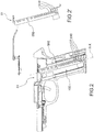
figure 2 is a side view of the firearm shown infigure 1 comprising the firearm device, comprised in the detection group; -
figure 2' is a side view of the firearm device comprised in the detection group, as infigure 1 ; -
figures 3a and 3b show a perspective and a side view of a carrier fitted with the magazine device comprised in the detection group; -
figure 4 shows a diagram of a gun fitted with the primary sensors comprised in the firearm device. - With reference to the appended drawings,
reference numeral 1 globally denotes a firearm in its entirety. - Preferably, said
firearm 1 comprises amagazine 10 housed in a specially shapedmagazine housing 100. - Preferably, the
magazine housing 100 extends along a magazine axis X-X. Similarly themagazine 10 also extends in height for example between a bullet input/output end suitable to be placed in a position proximal to the firing chamber of the weapon and a bottom end. - According to a preferred embodiment, the
magazine 10 is fitted with acarrier 11 suitable to keep at least one bullet housed in themagazine 10 near its input/output end; in other words, with themagazine 10 inserted in thefirearm 1, thecarrier 11 keeps a bullet in a position such as to be engaged by the firing mechanism to be promptly brought into the firing chamber. - In a preferred embodiment, the
carrier 11 is suitable to adopt a full magazine position, in which themagazine 10 contains all the bullets inside it and thecarrier 11 is thus lowered and proximal to the bottom end, and an empty magazine configuration, in which themagazine 10 is emptied of all the bullets inside it and thecarrier 11 is thus raised and proximal to the bullet input/output end. - Preferably, the
carrier 11 operates with a spring element in turn housed inside themagazine 10. - It is to be noted that in a preferred embodiment said
firearm 1 is a gun. Preferably, themagazine housing 100 is made in the grip of the gun. - In a further preferred embodiment said
firearm 1 is an assault rifle. - The
firearm 1 comprises a detection group suitable to detect the presence of themagazine 10 in themagazine housing 100 and suitable to detect the presence of a predefined number of bullets inside it. - As described in detail below, the detection group is suitable to be housed in the firearm without revolutionising its structure or influencing its kinematics.
- The detection group comprises a
firearm device 51 and amagazine device 52 suitable to be operatively connected to each other. - Specifically, the
firearm device 51 is suitable to be housed in thefirearm 1, in particular it is placed near the walls of themagazine housing 100. - In yet other words, the
firearm device 1 fits into firearm, for example in the grip of the gun. - Instead, the
magazine device 52 is housed in themagazine 10 of thefirearm 1, specifically, it is housed in thecarrier 11 of themagazine 10. In other words, themagazine device 52 is suitable to have an axial disposition in themagazine 10 induced by the position of thecarrier 11. - The
firearm device 51 comprises a plurality ofprimary sensors 510 positioned along the magazine device X-X. While themagazine device 52 comprises at least onesecondary sensor 520, suitable to be operatively connected with eachprimary sensor 510. - Each
primary sensor 510 comprises a mechanical switch. - In a preferred embodiment, the mechanical switch is a magnetic switch.
- In other words, the mechanical switch comprises an active portion adapted to be stressed to close the switch.
- Preferably, said active portion is in a ferromagnetic material.
- According to a preferred embodiment, the
secondary sensor 520 comprises a ferromagnetic element, preferably a permanent magnet, i.e. which has a magnetic field. - In other words, the mechanical switch, in particular the active portion, is suitable to close upon the action of the
secondary sensor 520. - The closure of the mechanical switch entails a change of resistance and the position of the closed mechanical switch position, which is a function of the position of the
carrier 11, and thus of the number of bullets housed in themagazine housing 100 loader, is thus establishable. - According to a preferred embodiment, the
secondary sensor 520 is embedded inside thecarrier 11. - According to the invention, the
carrier 11 is in a non-magnetic material. - According to a preferred embodiment, therefore, thanks to the position along the magazine axis X-X of a plurality of
primary sensors 510, as the height along the magazine axis X-X of thecarrier 11 varies, thesecondary sensor 520 performs an action on theprimary sensor 510 proximal to it. In other words, depending on the axial position of thecarrier 11 in themagazine 10, theprimary sensor 510 undergoes an action, for example such as to perform the closure of the respective switch. - According to a preferred embodiment, the
primary sensors 510 are in a number equal to the number of possible positions of thecarrier 11. - In a preferred embodiment, the
primary sensors 510 are in a number equal to the maximum number of bullets which are housable in themagazine 10. - In a preferred embodiment, the
primary sensors 510 are in a number equal to the maximum number of bullets which are housable in themagazine housing 100. - According to a preferred embodiment, the
firearm device 51 comprises asupport element 550 suitable to support and house the plurality ofprimary sensors 510 in such a way as to connect them electrically to each other. - Preferably, the
support element 550 extends in length and is suitable to be placed in the firearm facing the magazine, extending along the magazine axis X-X. - Preferably, the
support element 550 is in non-magnetic material. - In a preferred embodiment, the
magazine housing 100 comprises a detector seat which extends along the magazine axis X-X suitable for housing thefirearm device 51. Preferably, thesupport element 550 and the primary sensors (510) housed on it, are housed in said detector seat. - Preferably, the
support element 550 is suitable to be inserted in thefirearm 1 in the direction of the magazine axis X-X. - Preferably, the
support element 550 is an electronic terminal board on which theprimary sensor elements 510 and the electronic circuitry which puts them in mutual communication are housed. - According to a preferred embodiment, the detection group comprises a data processing unit suitable to manage the information derived from the
primary sensors 510. - Preferably, the detection group by means of the data processing unit is suitable to manage the information, for example transmitting it to another electronic device inside or outside the
firearm 1. In further embodiments the detection group by means of the data processing unit is suitable to store the information in a special memory. - Preferably, the detection group is suitable to transmit the information detected to a mobile phone or smartphone.
- Innovatively the firearm according to the present invention resolves the problems typical of the prior art, being suitable to detect the aforesaid information relative to the status of the magazine.
- Advantageously, in fact, the firearm according to the invention is suitable to detect in the first place the presence or absence of the magazine in the magazine housing and secondly the number of bullets housed in it. Advantageously, the firearm according to the present invention is suitable to detect the presence of bullets housed in said magazine.
- In addition, advantageously, the firearm according to the invention, achieves the purpose set forth comprising a detection group which does not affect the firearm itself. It is not in fact necessary to revolutionize the shape or design of the firearm. Advantageously the operations on the firearm to comprise and house the detection group are minimal and substantially non-invasive.
- An additional advantage is therefore that the firearm according to the invention, despite comprising a detection group shows no change in shooting kinematics, the detection group not being invasive of the firing mechanism of the firearm.
- Yet a further advantage lies in that the detection group comprises a plurality of components composed of magnetic elements which, however, are designed to be suitable to operate with each other without magnetizing the other components comprised in the weapon.
- Advantageously, the detection group is simple and reliable to make, guaranteeing over time a correct detection of the presence of the magazine and of the bullets stored therein. In other words, advantageously, the use of mechanical components ensures a reliable and effective detection even with high peak stresses suffered by the firearm, for example due to the firing event.
- In addition, advantageously, even the management of the detection group is simple to implement, not presenting details and complex systems or electronic circuitry, the management, implementation and reliability of which is always in discussion, all the more so in a hostile environment such as that of a firearm, which typically suffers critical and impulsive stresses. Advantageously, the firearm according to the present invention is suitable to allow over time the aforesaid detection even after sustaining impulsive stresses such as those of a gunshot. Advantageously, the switches are indeed suitable to withstand up to 5000g.
- According to yet a further advantageous aspect, the non-invasiveness of the detection group of the present invention makes it suitable to be comprised in firearms of small dimensions, such as a gun. Advantageously, the aforesaid advantages are thus also achievable on a gun comprising a detection group.
- Advantageously, the detection group is suitable to consume very little energy in its implementation, activating in fact only upon a change of resistance, i.e. only if the shot fired event occurs and the number of bullets housed in the magazine housing changes. If said event does not occur, the detection group has all the switches open and therefore does not consume energy.
- In a further embodiment, the carrier (11) is of the type comprising a dummy bullet, and the magazine device (52) is housed in said dummy bullet.
- It is clear that a person skilled in the art may make modifications to the firearm described above so as to satisfy contingent requirements while remaining within the sphere of protection of the following claims.
Claims (10)
- Firearm (1) comprising a magazine (10), fitted with a carrier (11) in a non-magnetic material, housed in a specially shaped magazine housing (100) which extends along a magazine axis (X-X), wherein the firearm (1) comprises a detection group suitable to detect the presence of the magazine (10) in the magazine housing (100) and the presence of a predefined number of bullets inside it, comprising:i) a firearm device (51), housed in the firearm (1), preferably near the walls of the magazine housing (100), comprising a plurality of primary sensors (510) arranged along the magazine axis (X-X), wherein each primary sensor (510) comprises a mechanical switch;ii) a magazine device (52), housed in the carrier (11) of the magazine (10), comprising at least a secondary sensor (520), comprising a ferromagnetic element yielding a magnetic field, wherein the carrier (11) is of the type comprising a dummy bullet and the secondary sensor (520) is housed in said dummy bullet or wherein the secondary sensor (520) is embedded inside the carrier (11);in which at the change in height along the magazine axis (X-X) of the carrier (11) the secondary sensor (520) by means of its magnetic field performs an action on the primary sensor (510) proximal to it to perform the closing of the respective mechanical switch.
- Firearm (1) according to claim 1, wherein the mechanical switch is a magnetic switch comprising an active portion, preferably of ferromagnetic material, suitable to close upon the action of the secondary sensor (520).
- Firearm (1) according to any of the previous claims, wherein the ferromagnetic element comprised in the secondary sensor (520) is a permanent magnet.
- Firearm (1) according to any one of the previous claims, wherein the primary sensors (510) are in a number equal to the number of positions that the carrier (11) is suitable to assume between a configuration of magazine full, in which the magazine (10) contains all the bullets inside it, and a configuration of magazine empty, in which the magazine (10) is emptied of all the bullets inside it.
- Firearm (1) according to any of the preceding claims, wherein the primary sensors (510) are in a number such as to count the number of bullets housed inside the magazine housing(100).
- Firearm (1) according to any of the preceding claims, wherein the firearm device (1) comprises a support element (550) suitable to support and house the plurality of primary sensors (510) in such a way as to connect them electrically to each other.
- Firearm (1) according to any of the previous claims, wherein the magazine housing (100) comprises a detector seat (115) which extends along the magazine axis (X-X) suitable for housing the firearm device(51).
- Firearm (1) according to any of the preceding claims, wherein the detection group comprises a data processing unit suitable to manage the information deriving from the primary sensors (510), for example, to transmit it to another electronic device inside or outside the firearm (1) .
- Firearm (1) according to any of the previous claims, wherein said firearm (1) is a handgun.
- Firearm (1) according to any of the previous claims from 1 to 8, wherein said firearm (1) is an assault rifle.
Applications Claiming Priority (2)
| Application Number | Priority Date | Filing Date | Title |
|---|---|---|---|
| ITBS20150082 | 2015-05-14 | ||
| PCT/IB2016/051786 WO2016181234A1 (en) | 2015-05-14 | 2016-03-30 | Firearm comprising a magazine detection group |
Publications (2)
| Publication Number | Publication Date |
|---|---|
| EP3295110A1 EP3295110A1 (en) | 2018-03-21 |
| EP3295110B1 true EP3295110B1 (en) | 2019-05-15 |
Family
ID=53900900
Family Applications (1)
| Application Number | Title | Priority Date | Filing Date |
|---|---|---|---|
| EP16723517.5A Active EP3295110B1 (en) | 2015-05-14 | 2016-03-30 | Firearm comprising a magazine detection group |
Country Status (3)
| Country | Link |
|---|---|
| US (1) | US20180128563A1 (en) |
| EP (1) | EP3295110B1 (en) |
| WO (1) | WO2016181234A1 (en) |
Families Citing this family (14)
| Publication number | Priority date | Publication date | Assignee | Title |
|---|---|---|---|---|
| US20190222771A1 (en) | 2016-10-14 | 2019-07-18 | Laser Aiming Systems Corporation | Gun-mounted recording device |
| GB2560744A (en) * | 2017-03-23 | 2018-09-26 | Winton Taylor Richard | Round-Counting Device |
| US10962314B2 (en) | 2017-04-12 | 2021-03-30 | Laser Aiming Systems Corporation | Firearm including electronic components to enhance user experience |
| EP3762674A4 (en) | 2018-03-08 | 2021-11-24 | Maztech Industries, LLC | SYSTEM FOR DETECTION OF THE AVAILABILITY OF ARMS AMMUNITION |
| WO2020086598A1 (en) | 2018-10-22 | 2020-04-30 | Magpul Industries Corp. | Determination of round count by hall switch encoding |
| US11719497B2 (en) | 2018-10-22 | 2023-08-08 | Magpul Industries Corp. | Determination of round count by hall switch encoding |
| US11971238B2 (en) * | 2018-10-22 | 2024-04-30 | Magpul Industries Corp. | Determination of round count by hall switch encoding |
| US11519692B2 (en) * | 2020-04-20 | 2022-12-06 | Sig Sauer, Inc. | Sight assembly and system with firearm status indicator |
| US12173992B1 (en) | 2020-07-21 | 2024-12-24 | Laser Aiming Systems Corporation | Gun mounted recording device with quick release battery |
| US12130121B1 (en) | 2020-07-21 | 2024-10-29 | Laser Aiming Systems Corporation | Data redundancy and hardware tracking system for gun-mounted recording device |
| WO2023086840A1 (en) | 2021-11-12 | 2023-05-19 | Maztech Industries, LLC | Firearm ammunition availability detection system |
| KR20240154530A (en) * | 2022-01-11 | 2024-10-25 | 맥펄 인더스트리즈 코프. | Firearm magazine with round counter |
| US11815332B2 (en) | 2022-03-16 | 2023-11-14 | Sig Sauer, Inc. | Weapon sight |
| US12416461B1 (en) * | 2024-05-17 | 2025-09-16 | Jonathan Elrod | Magazine capacity tracking system |
Family Cites Families (4)
| Publication number | Priority date | Publication date | Assignee | Title |
|---|---|---|---|---|
| US5052138A (en) * | 1989-12-01 | 1991-10-01 | Philip Crain | Ammunition supply indicating system |
| US5303495A (en) * | 1992-12-09 | 1994-04-19 | Harthcock Jerry D | Personal weapon system |
| US8191297B2 (en) * | 2009-08-04 | 2012-06-05 | Gwillim Jr Reese C | Device for indicating low ammunition in a firearm magazine |
| CA2788869A1 (en) * | 2010-02-04 | 2011-08-11 | Raul Delgado Acarreta | Ammunition supply indicator device |
-
2016
- 2016-03-30 WO PCT/IB2016/051786 patent/WO2016181234A1/en not_active Ceased
- 2016-03-30 US US15/573,170 patent/US20180128563A1/en not_active Abandoned
- 2016-03-30 EP EP16723517.5A patent/EP3295110B1/en active Active
Non-Patent Citations (1)
| Title |
|---|
| None * |
Also Published As
| Publication number | Publication date |
|---|---|
| WO2016181234A1 (en) | 2016-11-17 |
| EP3295110A1 (en) | 2018-03-21 |
| US20180128563A1 (en) | 2018-05-10 |
Similar Documents
| Publication | Publication Date | Title |
|---|---|---|
| US20180128563A1 (en) | Firearm comprising a magazine detection group | |
| JP4996963B2 (en) | Shooting detector, ammunition management device and fire bullet count counter | |
| EP3198216B1 (en) | Firearm with change configuration detection system | |
| US6643968B2 (en) | Pistol with a device for determining the number of shots | |
| US20170336160A1 (en) | Round counter for firearm | |
| US8826575B2 (en) | Self calibrating weapon shot counter | |
| US8046946B2 (en) | Shot-counting device for a firearm | |
| US20220373285A1 (en) | Smart Ammunition | |
| WO2011094177A3 (en) | Monitoring shots of firearms | |
| WO2005061983A1 (en) | A structure of detecting device used in miles system and gun simulator | |
| US20140182186A1 (en) | Video camera gun barrel mounting and programming system | |
| US8381426B2 (en) | System and method for weapon discharge inhibition | |
| WO2016019305A2 (en) | Trigger assembly of a precision guided firearm | |
| EP3295112B1 (en) | Gun comprising an electronic device | |
| KR20180055814A (en) | Systems to defend against threats | |
| CN101115967A (en) | bullet counter | |
| US11346626B2 (en) | Device, system and method for counting used munition | |
| WO2012027413A2 (en) | Laser aimed small arms ammunition | |
| US9568276B2 (en) | Tilt-activated laser aimed firearms ammunition | |
| GB2397128A (en) | Detecting and analysing the discharge from a firearm using a piezoelectric vibration sensor | |
| US12416461B1 (en) | Magazine capacity tracking system | |
| US10586645B2 (en) | Transformer systems and methods for operating a transformer system | |
| EP4081751B1 (en) | Lethal or non-lethal weapon assembly comprising a projectile launcher and an electronic control unit incorporated in the launcher, and electronic means, which is connected to the control unit for authorising or preventing firing | |
| EP3494354B1 (en) | Firearm comprising an electronic system | |
| US20250334369A1 (en) | Sear assembly for weapons |
Legal Events
| Date | Code | Title | Description |
|---|---|---|---|
| STAA | Information on the status of an ep patent application or granted ep patent |
Free format text: STATUS: THE INTERNATIONAL PUBLICATION HAS BEEN MADE |
|
| PUAI | Public reference made under article 153(3) epc to a published international application that has entered the european phase |
Free format text: ORIGINAL CODE: 0009012 |
|
| STAA | Information on the status of an ep patent application or granted ep patent |
Free format text: STATUS: REQUEST FOR EXAMINATION WAS MADE |
|
| 17P | Request for examination filed |
Effective date: 20170927 |
|
| AK | Designated contracting states |
Kind code of ref document: A1 Designated state(s): AL AT BE BG CH CY CZ DE DK EE ES FI FR GB GR HR HU IE IS IT LI LT LU LV MC MK MT NL NO PL PT RO RS SE SI SK SM TR |
|
| AX | Request for extension of the european patent |
Extension state: BA ME |
|
| DAV | Request for validation of the european patent (deleted) | ||
| DAX | Request for extension of the european patent (deleted) | ||
| GRAP | Despatch of communication of intention to grant a patent |
Free format text: ORIGINAL CODE: EPIDOSNIGR1 |
|
| STAA | Information on the status of an ep patent application or granted ep patent |
Free format text: STATUS: GRANT OF PATENT IS INTENDED |
|
| INTG | Intention to grant announced |
Effective date: 20181214 |
|
| GRAS | Grant fee paid |
Free format text: ORIGINAL CODE: EPIDOSNIGR3 |
|
| GRAA | (expected) grant |
Free format text: ORIGINAL CODE: 0009210 |
|
| STAA | Information on the status of an ep patent application or granted ep patent |
Free format text: STATUS: THE PATENT HAS BEEN GRANTED |
|
| AK | Designated contracting states |
Kind code of ref document: B1 Designated state(s): AL AT BE BG CH CY CZ DE DK EE ES FI FR GB GR HR HU IE IS IT LI LT LU LV MC MK MT NL NO PL PT RO RS SE SI SK SM TR |
|
| REG | Reference to a national code |
Ref country code: CH Ref legal event code: EP |
|
| REG | Reference to a national code |
Ref country code: DE Ref legal event code: R096 Ref document number: 602016014026 Country of ref document: DE |
|
| REG | Reference to a national code |
Ref country code: IE Ref legal event code: FG4D |
|
| REG | Reference to a national code |
Ref country code: NL Ref legal event code: MP Effective date: 20190515 |
|
| REG | Reference to a national code |
Ref country code: LT Ref legal event code: MG4D |
|
| PG25 | Lapsed in a contracting state [announced via postgrant information from national office to epo] |
Ref country code: FI Free format text: LAPSE BECAUSE OF FAILURE TO SUBMIT A TRANSLATION OF THE DESCRIPTION OR TO PAY THE FEE WITHIN THE PRESCRIBED TIME-LIMIT Effective date: 20190515 Ref country code: NO Free format text: LAPSE BECAUSE OF FAILURE TO SUBMIT A TRANSLATION OF THE DESCRIPTION OR TO PAY THE FEE WITHIN THE PRESCRIBED TIME-LIMIT Effective date: 20190815 Ref country code: LT Free format text: LAPSE BECAUSE OF FAILURE TO SUBMIT A TRANSLATION OF THE DESCRIPTION OR TO PAY THE FEE WITHIN THE PRESCRIBED TIME-LIMIT Effective date: 20190515 Ref country code: NL Free format text: LAPSE BECAUSE OF FAILURE TO SUBMIT A TRANSLATION OF THE DESCRIPTION OR TO PAY THE FEE WITHIN THE PRESCRIBED TIME-LIMIT Effective date: 20190515 Ref country code: PT Free format text: LAPSE BECAUSE OF FAILURE TO SUBMIT A TRANSLATION OF THE DESCRIPTION OR TO PAY THE FEE WITHIN THE PRESCRIBED TIME-LIMIT Effective date: 20190915 Ref country code: AL Free format text: LAPSE BECAUSE OF FAILURE TO SUBMIT A TRANSLATION OF THE DESCRIPTION OR TO PAY THE FEE WITHIN THE PRESCRIBED TIME-LIMIT Effective date: 20190515 Ref country code: ES Free format text: LAPSE BECAUSE OF FAILURE TO SUBMIT A TRANSLATION OF THE DESCRIPTION OR TO PAY THE FEE WITHIN THE PRESCRIBED TIME-LIMIT Effective date: 20190515 Ref country code: HR Free format text: LAPSE BECAUSE OF FAILURE TO SUBMIT A TRANSLATION OF THE DESCRIPTION OR TO PAY THE FEE WITHIN THE PRESCRIBED TIME-LIMIT Effective date: 20190515 Ref country code: SE Free format text: LAPSE BECAUSE OF FAILURE TO SUBMIT A TRANSLATION OF THE DESCRIPTION OR TO PAY THE FEE WITHIN THE PRESCRIBED TIME-LIMIT Effective date: 20190515 |
|
| PG25 | Lapsed in a contracting state [announced via postgrant information from national office to epo] |
Ref country code: GR Free format text: LAPSE BECAUSE OF FAILURE TO SUBMIT A TRANSLATION OF THE DESCRIPTION OR TO PAY THE FEE WITHIN THE PRESCRIBED TIME-LIMIT Effective date: 20190816 Ref country code: LV Free format text: LAPSE BECAUSE OF FAILURE TO SUBMIT A TRANSLATION OF THE DESCRIPTION OR TO PAY THE FEE WITHIN THE PRESCRIBED TIME-LIMIT Effective date: 20190515 Ref country code: BG Free format text: LAPSE BECAUSE OF FAILURE TO SUBMIT A TRANSLATION OF THE DESCRIPTION OR TO PAY THE FEE WITHIN THE PRESCRIBED TIME-LIMIT Effective date: 20190815 Ref country code: RS Free format text: LAPSE BECAUSE OF FAILURE TO SUBMIT A TRANSLATION OF THE DESCRIPTION OR TO PAY THE FEE WITHIN THE PRESCRIBED TIME-LIMIT Effective date: 20190515 |
|
| REG | Reference to a national code |
Ref country code: AT Ref legal event code: MK05 Ref document number: 1133958 Country of ref document: AT Kind code of ref document: T Effective date: 20190515 |
|
| PG25 | Lapsed in a contracting state [announced via postgrant information from national office to epo] |
Ref country code: SK Free format text: LAPSE BECAUSE OF FAILURE TO SUBMIT A TRANSLATION OF THE DESCRIPTION OR TO PAY THE FEE WITHIN THE PRESCRIBED TIME-LIMIT Effective date: 20190515 Ref country code: EE Free format text: LAPSE BECAUSE OF FAILURE TO SUBMIT A TRANSLATION OF THE DESCRIPTION OR TO PAY THE FEE WITHIN THE PRESCRIBED TIME-LIMIT Effective date: 20190515 Ref country code: CZ Free format text: LAPSE BECAUSE OF FAILURE TO SUBMIT A TRANSLATION OF THE DESCRIPTION OR TO PAY THE FEE WITHIN THE PRESCRIBED TIME-LIMIT Effective date: 20190515 Ref country code: AT Free format text: LAPSE BECAUSE OF FAILURE TO SUBMIT A TRANSLATION OF THE DESCRIPTION OR TO PAY THE FEE WITHIN THE PRESCRIBED TIME-LIMIT Effective date: 20190515 Ref country code: DK Free format text: LAPSE BECAUSE OF FAILURE TO SUBMIT A TRANSLATION OF THE DESCRIPTION OR TO PAY THE FEE WITHIN THE PRESCRIBED TIME-LIMIT Effective date: 20190515 |
|
| REG | Reference to a national code |
Ref country code: DE Ref legal event code: R097 Ref document number: 602016014026 Country of ref document: DE |
|
| PG25 | Lapsed in a contracting state [announced via postgrant information from national office to epo] |
Ref country code: SM Free format text: LAPSE BECAUSE OF FAILURE TO SUBMIT A TRANSLATION OF THE DESCRIPTION OR TO PAY THE FEE WITHIN THE PRESCRIBED TIME-LIMIT Effective date: 20190515 |
|
| PLBE | No opposition filed within time limit |
Free format text: ORIGINAL CODE: 0009261 |
|
| STAA | Information on the status of an ep patent application or granted ep patent |
Free format text: STATUS: NO OPPOSITION FILED WITHIN TIME LIMIT |
|
| PG25 | Lapsed in a contracting state [announced via postgrant information from national office to epo] |
Ref country code: TR Free format text: LAPSE BECAUSE OF FAILURE TO SUBMIT A TRANSLATION OF THE DESCRIPTION OR TO PAY THE FEE WITHIN THE PRESCRIBED TIME-LIMIT Effective date: 20190515 |
|
| 26N | No opposition filed |
Effective date: 20200218 |
|
| PG25 | Lapsed in a contracting state [announced via postgrant information from national office to epo] |
Ref country code: PL Free format text: LAPSE BECAUSE OF FAILURE TO SUBMIT A TRANSLATION OF THE DESCRIPTION OR TO PAY THE FEE WITHIN THE PRESCRIBED TIME-LIMIT Effective date: 20190515 |
|
| PG25 | Lapsed in a contracting state [announced via postgrant information from national office to epo] |
Ref country code: SI Free format text: LAPSE BECAUSE OF FAILURE TO SUBMIT A TRANSLATION OF THE DESCRIPTION OR TO PAY THE FEE WITHIN THE PRESCRIBED TIME-LIMIT Effective date: 20190515 |
|
| PG25 | Lapsed in a contracting state [announced via postgrant information from national office to epo] |
Ref country code: MC Free format text: LAPSE BECAUSE OF FAILURE TO SUBMIT A TRANSLATION OF THE DESCRIPTION OR TO PAY THE FEE WITHIN THE PRESCRIBED TIME-LIMIT Effective date: 20190515 |
|
| REG | Reference to a national code |
Ref country code: CH Ref legal event code: PL |
|
| PG25 | Lapsed in a contracting state [announced via postgrant information from national office to epo] |
Ref country code: LU Free format text: LAPSE BECAUSE OF NON-PAYMENT OF DUE FEES Effective date: 20200330 |
|
| PG25 | Lapsed in a contracting state [announced via postgrant information from national office to epo] |
Ref country code: CH Free format text: LAPSE BECAUSE OF NON-PAYMENT OF DUE FEES Effective date: 20200331 Ref country code: LI Free format text: LAPSE BECAUSE OF NON-PAYMENT OF DUE FEES Effective date: 20200331 Ref country code: FR Free format text: LAPSE BECAUSE OF NON-PAYMENT OF DUE FEES Effective date: 20200331 Ref country code: IE Free format text: LAPSE BECAUSE OF NON-PAYMENT OF DUE FEES Effective date: 20200330 |
|
| GBPC | Gb: european patent ceased through non-payment of renewal fee |
Effective date: 20200330 |
|
| PG25 | Lapsed in a contracting state [announced via postgrant information from national office to epo] |
Ref country code: GB Free format text: LAPSE BECAUSE OF NON-PAYMENT OF DUE FEES Effective date: 20200330 |
|
| PG25 | Lapsed in a contracting state [announced via postgrant information from national office to epo] |
Ref country code: MT Free format text: LAPSE BECAUSE OF FAILURE TO SUBMIT A TRANSLATION OF THE DESCRIPTION OR TO PAY THE FEE WITHIN THE PRESCRIBED TIME-LIMIT Effective date: 20190515 Ref country code: CY Free format text: LAPSE BECAUSE OF FAILURE TO SUBMIT A TRANSLATION OF THE DESCRIPTION OR TO PAY THE FEE WITHIN THE PRESCRIBED TIME-LIMIT Effective date: 20190515 |
|
| PG25 | Lapsed in a contracting state [announced via postgrant information from national office to epo] |
Ref country code: RO Free format text: LAPSE BECAUSE OF FAILURE TO SUBMIT A TRANSLATION OF THE DESCRIPTION OR TO PAY THE FEE WITHIN THE PRESCRIBED TIME-LIMIT Effective date: 20190515 Ref country code: MK Free format text: LAPSE BECAUSE OF FAILURE TO SUBMIT A TRANSLATION OF THE DESCRIPTION OR TO PAY THE FEE WITHIN THE PRESCRIBED TIME-LIMIT Effective date: 20190515 Ref country code: IS Free format text: LAPSE BECAUSE OF FAILURE TO SUBMIT A TRANSLATION OF THE DESCRIPTION OR TO PAY THE FEE WITHIN THE PRESCRIBED TIME-LIMIT Effective date: 20190915 |
|
| P01 | Opt-out of the competence of the unified patent court (upc) registered |
Effective date: 20230522 |
|
| PGFP | Annual fee paid to national office [announced via postgrant information from national office to epo] |
Ref country code: DE Payment date: 20260325 Year of fee payment: 11 |
|
| PGFP | Annual fee paid to national office [announced via postgrant information from national office to epo] |
Ref country code: BE Payment date: 20260319 Year of fee payment: 11 Ref country code: IT Payment date: 20260107 Year of fee payment: 11 |