EP3295064B1 - Combined butterfly/ball valve - Google Patents
Combined butterfly/ball valve Download PDFInfo
- Publication number
- EP3295064B1 EP3295064B1 EP16723900.3A EP16723900A EP3295064B1 EP 3295064 B1 EP3295064 B1 EP 3295064B1 EP 16723900 A EP16723900 A EP 16723900A EP 3295064 B1 EP3295064 B1 EP 3295064B1
- Authority
- EP
- European Patent Office
- Prior art keywords
- valve
- valve member
- hybrid
- inlet
- flow
- Prior art date
- Legal status (The legal status is an assumption and is not a legal conclusion. Google has not performed a legal analysis and makes no representation as to the accuracy of the status listed.)
- Active
Links
Images




Classifications
-
- F—MECHANICAL ENGINEERING; LIGHTING; HEATING; WEAPONS; BLASTING
- F16—ENGINEERING ELEMENTS AND UNITS; GENERAL MEASURES FOR PRODUCING AND MAINTAINING EFFECTIVE FUNCTIONING OF MACHINES OR INSTALLATIONS; THERMAL INSULATION IN GENERAL
- F16K—VALVES; TAPS; COCKS; ACTUATING-FLOATS; DEVICES FOR VENTING OR AERATING
- F16K11/00—Multiple-way valves, e.g. mixing valves; Pipe fittings incorporating such valves
- F16K11/02—Multiple-way valves, e.g. mixing valves; Pipe fittings incorporating such valves with all movable sealing faces moving as one unit
- F16K11/08—Multiple-way valves, e.g. mixing valves; Pipe fittings incorporating such valves with all movable sealing faces moving as one unit comprising only taps or cocks
- F16K11/087—Multiple-way valves, e.g. mixing valves; Pipe fittings incorporating such valves with all movable sealing faces moving as one unit comprising only taps or cocks with spherical plug
- F16K11/0873—Multiple-way valves, e.g. mixing valves; Pipe fittings incorporating such valves with all movable sealing faces moving as one unit comprising only taps or cocks with spherical plug the plug being only rotatable around one spindle
-
- F—MECHANICAL ENGINEERING; LIGHTING; HEATING; WEAPONS; BLASTING
- F02—COMBUSTION ENGINES; HOT-GAS OR COMBUSTION-PRODUCT ENGINE PLANTS
- F02C—GAS-TURBINE PLANTS; AIR INTAKES FOR JET-PROPULSION PLANTS; CONTROLLING FUEL SUPPLY IN AIR-BREATHING JET-PROPULSION PLANTS
- F02C9/00—Controlling gas-turbine plants; Controlling fuel supply in air- breathing jet-propulsion plants
- F02C9/16—Control of working fluid flow
- F02C9/18—Control of working fluid flow by bleeding, bypassing or acting on variable working fluid interconnections between turbines or compressors or their stages
-
- F—MECHANICAL ENGINEERING; LIGHTING; HEATING; WEAPONS; BLASTING
- F16—ENGINEERING ELEMENTS AND UNITS; GENERAL MEASURES FOR PRODUCING AND MAINTAINING EFFECTIVE FUNCTIONING OF MACHINES OR INSTALLATIONS; THERMAL INSULATION IN GENERAL
- F16K—VALVES; TAPS; COCKS; ACTUATING-FLOATS; DEVICES FOR VENTING OR AERATING
- F16K1/00—Lift valves or globe valves, i.e. cut-off apparatus with closure members having at least a component of their opening and closing motion perpendicular to the closing faces
- F16K1/16—Lift valves or globe valves, i.e. cut-off apparatus with closure members having at least a component of their opening and closing motion perpendicular to the closing faces with pivoted closure-members
- F16K1/18—Lift valves or globe valves, i.e. cut-off apparatus with closure members having at least a component of their opening and closing motion perpendicular to the closing faces with pivoted closure-members with pivoted discs or flaps
- F16K1/22—Lift valves or globe valves, i.e. cut-off apparatus with closure members having at least a component of their opening and closing motion perpendicular to the closing faces with pivoted closure-members with pivoted discs or flaps with axis of rotation crossing the valve member, e.g. butterfly valves
- F16K1/222—Shaping of the valve member
-
- F—MECHANICAL ENGINEERING; LIGHTING; HEATING; WEAPONS; BLASTING
- F16—ENGINEERING ELEMENTS AND UNITS; GENERAL MEASURES FOR PRODUCING AND MAINTAINING EFFECTIVE FUNCTIONING OF MACHINES OR INSTALLATIONS; THERMAL INSULATION IN GENERAL
- F16K—VALVES; TAPS; COCKS; ACTUATING-FLOATS; DEVICES FOR VENTING OR AERATING
- F16K1/00—Lift valves or globe valves, i.e. cut-off apparatus with closure members having at least a component of their opening and closing motion perpendicular to the closing faces
- F16K1/16—Lift valves or globe valves, i.e. cut-off apparatus with closure members having at least a component of their opening and closing motion perpendicular to the closing faces with pivoted closure-members
- F16K1/18—Lift valves or globe valves, i.e. cut-off apparatus with closure members having at least a component of their opening and closing motion perpendicular to the closing faces with pivoted closure-members with pivoted discs or flaps
- F16K1/22—Lift valves or globe valves, i.e. cut-off apparatus with closure members having at least a component of their opening and closing motion perpendicular to the closing faces with pivoted closure-members with pivoted discs or flaps with axis of rotation crossing the valve member, e.g. butterfly valves
- F16K1/226—Shaping or arrangements of the sealing
- F16K1/2261—Shaping or arrangements of the sealing the sealing being arranged on the valve member
-
- F—MECHANICAL ENGINEERING; LIGHTING; HEATING; WEAPONS; BLASTING
- F16—ENGINEERING ELEMENTS AND UNITS; GENERAL MEASURES FOR PRODUCING AND MAINTAINING EFFECTIVE FUNCTIONING OF MACHINES OR INSTALLATIONS; THERMAL INSULATION IN GENERAL
- F16K—VALVES; TAPS; COCKS; ACTUATING-FLOATS; DEVICES FOR VENTING OR AERATING
- F16K1/00—Lift valves or globe valves, i.e. cut-off apparatus with closure members having at least a component of their opening and closing motion perpendicular to the closing faces
- F16K1/16—Lift valves or globe valves, i.e. cut-off apparatus with closure members having at least a component of their opening and closing motion perpendicular to the closing faces with pivoted closure-members
- F16K1/18—Lift valves or globe valves, i.e. cut-off apparatus with closure members having at least a component of their opening and closing motion perpendicular to the closing faces with pivoted closure-members with pivoted discs or flaps
- F16K1/22—Lift valves or globe valves, i.e. cut-off apparatus with closure members having at least a component of their opening and closing motion perpendicular to the closing faces with pivoted closure-members with pivoted discs or flaps with axis of rotation crossing the valve member, e.g. butterfly valves
- F16K1/226—Shaping or arrangements of the sealing
- F16K1/2263—Shaping or arrangements of the sealing the sealing being arranged on the valve seat
-
- F—MECHANICAL ENGINEERING; LIGHTING; HEATING; WEAPONS; BLASTING
- F16—ENGINEERING ELEMENTS AND UNITS; GENERAL MEASURES FOR PRODUCING AND MAINTAINING EFFECTIVE FUNCTIONING OF MACHINES OR INSTALLATIONS; THERMAL INSULATION IN GENERAL
- F16K—VALVES; TAPS; COCKS; ACTUATING-FLOATS; DEVICES FOR VENTING OR AERATING
- F16K11/00—Multiple-way valves, e.g. mixing valves; Pipe fittings incorporating such valves
- F16K11/02—Multiple-way valves, e.g. mixing valves; Pipe fittings incorporating such valves with all movable sealing faces moving as one unit
- F16K11/04—Multiple-way valves, e.g. mixing valves; Pipe fittings incorporating such valves with all movable sealing faces moving as one unit comprising only lift valves
- F16K11/052—Multiple-way valves, e.g. mixing valves; Pipe fittings incorporating such valves with all movable sealing faces moving as one unit comprising only lift valves with pivoted closure members, e.g. butterfly valves
-
- F—MECHANICAL ENGINEERING; LIGHTING; HEATING; WEAPONS; BLASTING
- F16—ENGINEERING ELEMENTS AND UNITS; GENERAL MEASURES FOR PRODUCING AND MAINTAINING EFFECTIVE FUNCTIONING OF MACHINES OR INSTALLATIONS; THERMAL INSULATION IN GENERAL
- F16K—VALVES; TAPS; COCKS; ACTUATING-FLOATS; DEVICES FOR VENTING OR AERATING
- F16K11/00—Multiple-way valves, e.g. mixing valves; Pipe fittings incorporating such valves
- F16K11/02—Multiple-way valves, e.g. mixing valves; Pipe fittings incorporating such valves with all movable sealing faces moving as one unit
- F16K11/04—Multiple-way valves, e.g. mixing valves; Pipe fittings incorporating such valves with all movable sealing faces moving as one unit comprising only lift valves
- F16K11/052—Multiple-way valves, e.g. mixing valves; Pipe fittings incorporating such valves with all movable sealing faces moving as one unit comprising only lift valves with pivoted closure members, e.g. butterfly valves
- F16K11/0525—Multiple-way valves, e.g. mixing valves; Pipe fittings incorporating such valves with all movable sealing faces moving as one unit comprising only lift valves with pivoted closure members, e.g. butterfly valves the closure members being pivoted around an essentially central axis
-
- F—MECHANICAL ENGINEERING; LIGHTING; HEATING; WEAPONS; BLASTING
- F16—ENGINEERING ELEMENTS AND UNITS; GENERAL MEASURES FOR PRODUCING AND MAINTAINING EFFECTIVE FUNCTIONING OF MACHINES OR INSTALLATIONS; THERMAL INSULATION IN GENERAL
- F16K—VALVES; TAPS; COCKS; ACTUATING-FLOATS; DEVICES FOR VENTING OR AERATING
- F16K11/00—Multiple-way valves, e.g. mixing valves; Pipe fittings incorporating such valves
- F16K11/02—Multiple-way valves, e.g. mixing valves; Pipe fittings incorporating such valves with all movable sealing faces moving as one unit
- F16K11/04—Multiple-way valves, e.g. mixing valves; Pipe fittings incorporating such valves with all movable sealing faces moving as one unit comprising only lift valves
- F16K11/056—Multiple-way valves, e.g. mixing valves; Pipe fittings incorporating such valves with all movable sealing faces moving as one unit comprising only lift valves with ball-shaped valve members
-
- F—MECHANICAL ENGINEERING; LIGHTING; HEATING; WEAPONS; BLASTING
- F16—ENGINEERING ELEMENTS AND UNITS; GENERAL MEASURES FOR PRODUCING AND MAINTAINING EFFECTIVE FUNCTIONING OF MACHINES OR INSTALLATIONS; THERMAL INSULATION IN GENERAL
- F16K—VALVES; TAPS; COCKS; ACTUATING-FLOATS; DEVICES FOR VENTING OR AERATING
- F16K5/00—Plug valves; Taps or cocks comprising only cut-off apparatus having at least one of the sealing faces shaped as a more or less complete surface of a solid of revolution, the opening and closing movement being predominantly rotary
- F16K5/06—Plug valves; Taps or cocks comprising only cut-off apparatus having at least one of the sealing faces shaped as a more or less complete surface of a solid of revolution, the opening and closing movement being predominantly rotary with plugs having spherical surfaces; Packings therefor
- F16K5/0663—Packings
- F16K5/0684—Packings on the plug
-
- F—MECHANICAL ENGINEERING; LIGHTING; HEATING; WEAPONS; BLASTING
- F16—ENGINEERING ELEMENTS AND UNITS; GENERAL MEASURES FOR PRODUCING AND MAINTAINING EFFECTIVE FUNCTIONING OF MACHINES OR INSTALLATIONS; THERMAL INSULATION IN GENERAL
- F16K—VALVES; TAPS; COCKS; ACTUATING-FLOATS; DEVICES FOR VENTING OR AERATING
- F16K5/00—Plug valves; Taps or cocks comprising only cut-off apparatus having at least one of the sealing faces shaped as a more or less complete surface of a solid of revolution, the opening and closing movement being predominantly rotary
- F16K5/06—Plug valves; Taps or cocks comprising only cut-off apparatus having at least one of the sealing faces shaped as a more or less complete surface of a solid of revolution, the opening and closing movement being predominantly rotary with plugs having spherical surfaces; Packings therefor
- F16K5/0663—Packings
- F16K5/0689—Packings between housing and plug
-
- F—MECHANICAL ENGINEERING; LIGHTING; HEATING; WEAPONS; BLASTING
- F16—ENGINEERING ELEMENTS AND UNITS; GENERAL MEASURES FOR PRODUCING AND MAINTAINING EFFECTIVE FUNCTIONING OF MACHINES OR INSTALLATIONS; THERMAL INSULATION IN GENERAL
- F16K—VALVES; TAPS; COCKS; ACTUATING-FLOATS; DEVICES FOR VENTING OR AERATING
- F16K5/00—Plug valves; Taps or cocks comprising only cut-off apparatus having at least one of the sealing faces shaped as a more or less complete surface of a solid of revolution, the opening and closing movement being predominantly rotary
- F16K5/08—Details
- F16K5/12—Arrangements for modifying the way in which the rate of flow varies during the actuation of the valve
-
- F—MECHANICAL ENGINEERING; LIGHTING; HEATING; WEAPONS; BLASTING
- F05—INDEXING SCHEMES RELATING TO ENGINES OR PUMPS IN VARIOUS SUBCLASSES OF CLASSES F01-F04
- F05D—INDEXING SCHEME FOR ASPECTS RELATING TO NON-POSITIVE-DISPLACEMENT MACHINES OR ENGINES, GAS-TURBINES OR JET-PROPULSION PLANTS
- F05D2220/00—Application
- F05D2220/30—Application in turbines
-
- F—MECHANICAL ENGINEERING; LIGHTING; HEATING; WEAPONS; BLASTING
- F05—INDEXING SCHEMES RELATING TO ENGINES OR PUMPS IN VARIOUS SUBCLASSES OF CLASSES F01-F04
- F05D—INDEXING SCHEME FOR ASPECTS RELATING TO NON-POSITIVE-DISPLACEMENT MACHINES OR ENGINES, GAS-TURBINES OR JET-PROPULSION PLANTS
- F05D2240/00—Components
- F05D2240/20—Rotors
-
- F—MECHANICAL ENGINEERING; LIGHTING; HEATING; WEAPONS; BLASTING
- F05—INDEXING SCHEMES RELATING TO ENGINES OR PUMPS IN VARIOUS SUBCLASSES OF CLASSES F01-F04
- F05D—INDEXING SCHEME FOR ASPECTS RELATING TO NON-POSITIVE-DISPLACEMENT MACHINES OR ENGINES, GAS-TURBINES OR JET-PROPULSION PLANTS
- F05D2260/00—Function
- F05D2260/60—Fluid transfer
- F05D2260/606—Bypassing the fluid
Definitions
- This invention generally relates to turbine engines, and more specifically to apparatus and methods for modulating bleed air from the compressor stages of a turbine engine.
- bleed air from a compressor section of a turbine engine upstream from the combustion section.
- Such bleed air is used for a variety of functions including but not limited to cabin pressurization, engine operability, powering of pneumatic actuators, anti-icing, etc.
- Each air valve is in fluid communication with a certain portion of the compressor section. Controlling the restriction offered by the internal metering element of each air valve controls the amount of bleed air that is allowed to flow from the compressor section. This modulated bleed air flows from each air valve to its appropriate destination to achieve one or more of the exemplary functions identified above.
- Such contemporary systems are complex. Indeed, they typically involve multiple stand-alone air valves each having an independent actuator, or at least multiple separate metering elements controlled by a single actuator, each being connected to the single actuator by way of a relatively complex linkage.
- a stage of compressor section may utilize two stand-alone air valves each having an actuator, or a single valve having two metering elements therein which are connected by way of a linkage to a single actuator. While the above systems have proven to sufficiently modulate bleed air, they also have a large overall engine foot print, have a large part count, are generally complex in their linkages, and tend to be high cost.
- Recent designs have included a single metering element that allows for a primary bleed air function as well as a secondary function. While such systems present a significant improvement over existing designs, the applicant has found that for smaller bleed valve port sizes, on the order of about five centimeter (two inch) port diameter, (i.e. smaller bleed functions) such designs are not as efficient in terms of space and weight. That is, despite this smaller bleed function, such systems require a sufficiently large actuator to deal with internal resistive torque on the metering element. For smaller bleed functions, there is an expectation of smaller size and weight envelope as well, however. As such, there is a need in the art for an apparatus and method that modulates bleed air in smaller bleed applications that presents a reduced amount of internal frictional forces and resistive torque so as to reduce overall actuator size requirements.
- US 5,437,307 describes an intake bypass valve comprising a primary tubular member, the member having a cavity at its central extent for the receipt of a spherical ball; a secondary tubular member coupled to the primary member, the secondary member adapted to direct the fluid from the central extent of the primary member; and a spherical ball rotatably positioned within the recess of the primary member, the ball adapted to be rotated about an axis, the ball having a central aperture therethrough with a diameter, the ball also having a clapper plate pivotally located in the wall of the ball, the clapper plate including a spring adapted to resiliently urge the plate into a closed position wherein its exterior surface is co-extensive with the wall of the ball, the plate adapted to be moved into an open position wherein the clapper plate is located within the aperture of the ball.
- EP 1944535 describes a system that includes a radiating panel, a radiator, two distribution valves with rotary shutters, wherein one of the valves feeds the other one.
- FR 2919674 describes a device that has a tubular sectioned exhaust gas pipe for conveying exhaust gas along a direction parallel to a symmetrical axis, towards a hemispherical body at the interior of the pipe. The body is closed by a flat cylindrical surface and pivotingly mounted in a manner that the surface takes an obturation position that is perpendicular to the axis, and two positions that are co-linear to the axis. A partition is arranged in upstream of the body and separates the pipe into two tubular sectioned outlet pipes along the axis.
- a valve as defined in claim 1 which provides advantages of a butterfly valve as well as a ball valve in a single package.
- a valve includes a housing.
- the housing has an inlet, a primary outlet, and a secondary outlet.
- a hybrid valve member is rotatably positioned within the housing.
- the hybrid valve member has a fully closed position wherein the hybrid valve member prevents flow between the inlet and the primary outlet and prevents flow between the inlet and the secondary outlet.
- the hybrid valve member includes a planar portion and a hemispherical portion on a first side thereof. The planar portion faces the inlet in the fully closed position and the hemispherical portion faces the secondary outlet in the fully closed position.
- the hybrid valve member has a second side in an opposed relationship to the first side.
- the second side includes a planar portion.
- a seal groove is interposed between the first and second sides.
- a seal is positioned within the seal groove and provides a radial seal between the hybrid valve member and an interior surface of the housing.
- an aperture is formed through the hemispherical portion.
- the planar portion is exposed to a flow passing through the aperture.
- the aperture is selectively alignable with the secondary outlet such that a flow path extends between the inlet, the aperture, and the secondary outlet in at least a partially opened position of the hybrid valve member.
- the aperture may be an elongated slot having an open side.
- the hemispherical portion may also include an internal pocket.
- the internal pocket is offset from a center axis of the hybrid valve member.
- a flow feature may also be provided which extends from the planar portion of the second side of the hybrid valve member.
- the flow feature is positioned in an outer periphery of the hybrid valve member.
- the flow feature extends partially along the outer periphery of the hybrid valve member.
- the hemispherical portion may also face the inlet in the fully closed position.
- the valve may also include a valve shoe.
- the valve shoe is adjacent the secondary outlet and biased against the hemispherical portion to prevent a flow from the inlet to the secondary outlet in the fully closed position.
- a valve assembly can be provided.
- the valve assembly includes an actuator and a valve, the actuator being mounted to the valve.
- the valve includes a housing having an inlet, a primary outlet, and a secondary outlet.
- a hybrid valve member is rotatably positioned within the housing.
- a valve stem is connected to the hybrid valve member and extends through the housing such that a terminal end of the valve stem is connected to the actuator.
- the actuator is operable to rotate the valve stem about an actuation axis to thereby rotate the hybrid valve member within the housing.
- the hybrid valve member includes a first side with a planar portion and a hemispherical portion. The planar portion and at least part of the hemispherical portion face the inlet in a fully closed position of the valve member.
- the hemispherical portion of the hybrid valve member also faces the secondary outlet in the fully closed position of the hybrid valve member.
- the hybrid valve member includes a valve member seal which extends around an outer periphery of the hybrid valve member.
- the valve member seal is arranged to radially seal against an interior surface of the housing such that the valve member seal prevents a flow between the inlet and the primary outlet in the fully closed position of the hybrid valve member.
- the valve member seal is disposed within a plane which is transverse to the actuation axis.
- the valve may also include a valve shoe.
- the valve shoe is adjacent the secondary outlet and is biased against the hemispherical portion of the hybrid valve member to prevent a flow from the inlet to the secondary outlet in the fully closed position.
- a valve with a reduced weight and size envelope based in part upon a hybrid valve element and the sealing arrangement associated therewith.
- An embodiment according to this aspect includes a housing.
- the housing has an inlet, a primary outlet, and a secondary outlet.
- a hybrid valve member is rotatably positioned within the housing.
- the hybrid valve member includes a planar portion and a hemispherical portion on a first side thereof.
- a first seal arrangement and a second seal arrangement are also provided. The first seal arrangement sealingly engages an interior surface of the housing.
- a second seal arrangement sealingly engages the hemispherical portion of the hybrid valve member.
- An aperture is formed through the hemispherical portion, such that the planar portion is exposed to a flow passing through the aperture.
- the aperture is selectively alignable with the secondary outlet such that a flow path extends between the inlet, the aperture, and the secondary outlet in at least a partially opened position of the hybrid valve member.
- FIGS. 1-9 illustrate an exemplary embodiment of a valve and valve system according to the teachings of the present invention.
- the valve and valve system shown and described herein advantageously overcomes existing problems in the art by providing a single valve with a single valve member which is operable to govern multiple bleed flows from a compressor of a turbine engine.
- the valve and valve system described herein achieves the foregoing with a reduced weight and size footprint and lower actuation force requirements.
- Valve system 10 includes a valve 20.
- Valve 20 has an outer housing 22 with an inlet 24, a primary outlet 26 and a secondary outlet 28.
- inlet 24 may be connected to a section of a compressor of a turbine engine.
- a compressor bleed flow may be received through inlet 24 and selectively passed through primary outlet 26 for primary bleed flow functions such as pneumatic actuation of aircraft actuators.
- This bleed flow may also selectively pass through secondary outlet 28 for secondary bleed flow functions such as anti-icing.
- primary outlet 26 and secondary outlet 28 may be connected to other portions of an aircraft to provide various functionality.
- valve member 30 ( See e.g. FIG. 2 ) is disposed within an interior of housing 22.
- Valve member 30 is operably coupled to a valve stem 32 which extends along an actuation axis 34 of valve 20.
- An actuator 36 (shown schematically herein) is coupled to valve stem 32 to rotate the same about actuation axis 34 ultimately to govern a position of valve member 30 within housing 22.
- Actuator 36 may be any appropriate actuator designed for actuating a valve-type apparatus.
- actuator 36 may be a linear, rotary, hydraulic, fueldraulic, or an electromagnetic-type actuator.
- inlet 24 and primary outlet 26 are arranged along a primary flow axis 38.
- Secondary outlet 28 is arranged along a secondary flow axis 40.
- secondary flow axis 40 is transverse to primary flow axis 38 at an angle ⁇ which is less than 90°.
- Such an arrangement should be taken by way of example only, as it is entirely conceivable that secondary outlet 28 may be arranged along a secondary flow axis which is greater than or equal to 90° in other embodiments.
- valve 20 is shown in a cross-section to expose the internal componentry thereof.
- Valve member 30 and valve stem 32 are rotationally supported relative to housing 22 by first and second bearings 50, 52.
- a first housing cap 54 encloses first bearing 50 as shown, while a second housing cap 56 encloses second bearing 52 as shown.
- Appropriate seals 58 are positioned between first and second housing caps 54, 56 to prevent leakage at the interface between first and second housing caps 54, 56 and the remainder of housing 22.
- a valve stem seal 60 is provided around upper portion of valve stem 32 to prevent leakage at the area where valve stem 32 extends through housing 22 to engage actuator 36 ( See FIG. 1 ).
- valve member 30 also includes a valve member seal 72 which is disposed within a plane P that is transverse to actuation axis 34 as can be seen in FIG. 2 .
- This valve member seal 72 provides a first seal arrangement of valve 20.
- valve member 30 may be considered to be a hybrid valve member that includes portions thereof which are indicative of a butterfly valve-style valve member, but also portions which are indicative of a ball valve-style valve member. More specifically, valve member 30 includes a first side 62 and a second side 64. First side 62 includes a planar portion 66 and a hemispherical portion 68.
- planar portion 66 resembles a face of a butterfly valve element, while hemispherical portion 68 resembles a portion of a ball valve member.
- a seal groove 70 is interposed between first and second sides 62, 64 to receive valve member seal 72 introduced above relative to FIG. 2 .
- a slotted aperture 74 is formed in hemispherical portion 68. Slotted aperture 74 is selectively alignable with secondary outlet 28 as will be described in greater detail below relative to FIGS. 6-9 .
- Hemispherical portion 68 also includes a pocket 76 which is generally adjacent a center axis of valve member 30. Pocket 76 advantageously provides a contoured surface which aids in smoothing out the flow contour in this region, as well as prevents an undesirable pressure drop or recirculation zone.
- valve member 30 also includes a receiving feature 82 which extend partially through second side 64 as well as first side 62. Receiving feature 82 receives valve stem 32 ( See FIG. 2 ). An aperture 84 is also formed through receiving feature 82 for receipt of a fastener to fixedly retain valve member 30 relative to valve stem 32.
- second side 64 includes a planar surface 86 from which a flow feature 88 extends from.
- This flow feature 88 is positioned at a peripheral edge of valve member 30 and extends along a portion of the outer periphery thereof.
- Flow feature 88 acts as a dam or restriction to the flow when valve member 30 is an a partially or fully open position. This restriction acts to introduce or build up a higher pressure adjacent inlet 24 so that the flow is urged under this pressure build up towards secondary outlet 28 in addition to flowing through primary outlet 26.
- the particular shape of flow feature 88 illustrated is for exemplary purposes only, and other shapes may be utilized. Further, flow feature 88 may be entirely omitted in other embodiments.
- valve member 30 is shown in a fully closed position. As a result, flow from inlet 24 to primary outlet 26 as well as from inlet 24 to secondary outlet 28 is prevented. As can also be seen in this view, the first seal arrangement provided by valve member seal 72 is shown. Valve member seal 72 sealingly engages an interior surface 96 of housing 22 in the fully closed position. Also shown in FIG. 6 is a second seal arrangement formed between valve member 30 and secondary outlet 28. This seal arrangement includes a valve shoe 90.
- valve shoe 90 is biased by a biasing element 92 into engagement with hemispherical portion 68 as shown.
- a biasing element 92 As can be seen in FIG. 6 , an end edge of valve shoe 90 which engages hemispherical portion 68 is tapered so that it generally assumes the same outer peripheral shape of hemispherical portion 68.
- This close geometrical compliance combined with the biasing force provided by biasing element 92 provides a seal between hemispherical portion 68 and valve shoe 90 in the fully closed position.
- An additional seal 94 is provided adjacent biasing element 92 to prevent or minimize leakage at the interface between valve shoe 90 and housing 22.
- valve member 30 has been partially rotated in rotational direction 98 such that the seal formed between valve member seal 72 and interior surface 96 is broken. As a result, a flow F is permitted between inlet 24 and primary outlet 26. As can be seen from inspection of FIG. 7 , however, valve shoe 90 still fully engages hemispherical portion 68 such that flow from inlet 24 through aperture 74 is prevented.
- valve member 30 in rotational direction 98 will also open a flow path from inlet 24 through aperture 74 and secondary outlet 28. As a result, a flow F is permitted from inlet 20 to each of primary and secondary outlets 26, 28.
- valve member 30 In this fully opened position, valve member 30 presents a minimized flow restriction relative to the flow F from inlet 24 to primary outlet 26 as well as from inlet 24 to secondary outlet 28.
- valve member 30 presents a generally minimized construction in both size and width while also achieving structural features of both a butterfly valve member as well as a ball valve member.
- This construction allows for a first and second seal arrangement as described above which permits for a reduction in actuation forces.
- actuator requirements of valve assembly 10 See FIG. 1 ) are substantially reduced. This has the advantage of allowing for an overall reduced weight and size of the assembly.
Landscapes
- Engineering & Computer Science (AREA)
- General Engineering & Computer Science (AREA)
- Mechanical Engineering (AREA)
- Chemical & Material Sciences (AREA)
- Combustion & Propulsion (AREA)
- Physics & Mathematics (AREA)
- Fluid Mechanics (AREA)
- Lift Valve (AREA)
Description
- This invention generally relates to turbine engines, and more specifically to apparatus and methods for modulating bleed air from the compressor stages of a turbine engine.
- It is generally known in the art to syphon or "bleed" air from a compressor section of a turbine engine upstream from the combustion section. Such bleed air is used for a variety of functions including but not limited to cabin pressurization, engine operability, powering of pneumatic actuators, anti-icing, etc.
- Many contemporary systems modulate such bleed air through the use of multiple air valves. Each air valve is in fluid communication with a certain portion of the compressor section. Controlling the restriction offered by the internal metering element of each air valve controls the amount of bleed air that is allowed to flow from the compressor section. This modulated bleed air flows from each air valve to its appropriate destination to achieve one or more of the exemplary functions identified above.
- Unfortunately, such contemporary systems are complex. Indeed, they typically involve multiple stand-alone air valves each having an independent actuator, or at least multiple separate metering elements controlled by a single actuator, each being connected to the single actuator by way of a relatively complex linkage. As one example, a stage of compressor section may utilize two stand-alone air valves each having an actuator, or a single valve having two metering elements therein which are connected by way of a linkage to a single actuator. While the above systems have proven to sufficiently modulate bleed air, they also have a large overall engine foot print, have a large part count, are generally complex in their linkages, and tend to be high cost.
- Recent designs have included a single metering element that allows for a primary bleed air function as well as a secondary function. While such systems present a significant improvement over existing designs, the applicant has found that for smaller bleed valve port sizes, on the order of about five centimeter (two inch) port diameter, (i.e. smaller bleed functions) such designs are not as efficient in terms of space and weight. That is, despite this smaller bleed function, such systems require a sufficiently large actuator to deal with internal resistive torque on the metering element. For smaller bleed functions, there is an expectation of smaller size and weight envelope as well, however. As such, there is a need in the art for an apparatus and method that modulates bleed air in smaller bleed applications that presents a reduced amount of internal frictional forces and resistive torque so as to reduce overall actuator size requirements.
- The invention provides such an apparatus and method. These and other advantages of the invention, as well as additional inventive features, will be apparent from the description of the invention provided herein.
US 5,437,307 describes an intake bypass valve comprising a primary tubular member, the member having a cavity at its central extent for the receipt of a spherical ball; a secondary tubular member coupled to the primary member, the secondary member adapted to direct the fluid from the central extent of the primary member; and a spherical ball rotatably positioned within the recess of the primary member, the ball adapted to be rotated about an axis, the ball having a central aperture therethrough with a diameter, the ball also having a clapper plate pivotally located in the wall of the ball, the clapper plate including a spring adapted to resiliently urge the plate into a closed position wherein its exterior surface is co-extensive with the wall of the ball, the plate adapted to be moved into an open position wherein the clapper plate is located within the aperture of the ball.
EP 1944535 describes a system that includes a radiating panel, a radiator, two distribution valves with rotary shutters, wherein one of the valves feeds the other one.
FR 2919674 - In one aspect, a valve as defined in claim 1 is provided which provides advantages of a butterfly valve as well as a ball valve in a single package. Such a valve includes a housing. The housing has an inlet, a primary outlet, and a secondary outlet. A hybrid valve member is rotatably positioned within the housing. The hybrid valve member has a fully closed position wherein the hybrid valve member prevents flow between the inlet and the primary outlet and prevents flow between the inlet and the secondary outlet. The hybrid valve member includes a planar portion and a hemispherical portion on a first side thereof. The planar portion faces the inlet in the fully closed position and the hemispherical portion faces the secondary outlet in the fully closed position.
- Also, the hybrid valve member has a second side in an opposed relationship to the first side. The second side includes a planar portion. A seal groove is interposed between the first and second sides. A seal is positioned within the seal groove and provides a radial seal between the hybrid valve member and an interior surface of the housing.
- In certain embodiments, an aperture is formed through the hemispherical portion. The planar portion is exposed to a flow passing through the aperture. The aperture is selectively alignable with the secondary outlet such that a flow path extends between the inlet, the aperture, and the secondary outlet in at least a partially opened position of the hybrid valve member. The aperture may be an elongated slot having an open side.
- The hemispherical portion may also include an internal pocket. The internal pocket is offset from a center axis of the hybrid valve member.
- In certain embodiments, a flow feature may also be provided which extends from the planar portion of the second side of the hybrid valve member. The flow feature is positioned in an outer periphery of the hybrid valve member. The flow feature extends partially along the outer periphery of the hybrid valve member.
- In addition to facing the secondary outlet in the fully closed position, the hemispherical portion may also face the inlet in the fully closed position.
- In certain embodiments, the valve may also include a valve shoe. The valve shoe is adjacent the secondary outlet and biased against the hemispherical portion to prevent a flow from the inlet to the secondary outlet in the fully closed position.
- A valve assembly can be provided. The valve assembly includes an actuator and a valve, the actuator being mounted to the valve. The valve includes a housing having an inlet, a primary outlet, and a secondary outlet. A hybrid valve member is rotatably positioned within the housing. A valve stem is connected to the hybrid valve member and extends through the housing such that a terminal end of the valve stem is connected to the actuator. The actuator is operable to rotate the valve stem about an actuation axis to thereby rotate the hybrid valve member within the housing. The hybrid valve member includes a first side with a planar portion and a hemispherical portion. The planar portion and at least part of the hemispherical portion face the inlet in a fully closed position of the valve member. The hemispherical portion of the hybrid valve member also faces the secondary outlet in the fully closed position of the hybrid valve member. The hybrid valve member includes a valve member seal which extends around an outer periphery of the hybrid valve member. The valve member seal is arranged to radially seal against an interior surface of the housing such that the valve member seal prevents a flow between the inlet and the primary outlet in the fully closed position of the hybrid valve member. The valve member seal is disposed within a plane which is transverse to the actuation axis.
- The valve may also include a valve shoe. The valve shoe is adjacent the secondary outlet and is biased against the hemispherical portion of the hybrid valve member to prevent a flow from the inlet to the secondary outlet in the fully closed position.
- In a related example, a valve with a reduced weight and size envelope based in part upon a hybrid valve element and the sealing arrangement associated therewith. An embodiment according to this aspect includes a housing. The housing has an inlet, a primary outlet, and a secondary outlet. A hybrid valve member is rotatably positioned within the housing. The hybrid valve member includes a planar portion and a hemispherical portion on a first side thereof. A first seal arrangement and a second seal arrangement are also provided. The first seal arrangement sealingly engages an interior surface of the housing. A second seal arrangement sealingly engages the hemispherical portion of the hybrid valve member.
- An aperture is formed through the hemispherical portion, such that the planar portion is exposed to a flow passing through the aperture. The aperture is selectively alignable with the secondary outlet such that a flow path extends between the inlet, the aperture, and the secondary outlet in at least a partially opened position of the hybrid valve member.
- Other aspects, objectives and advantages of the invention will become more apparent from the following detailed description when taken in conjunction with the accompanying drawings.
- The accompanying drawings incorporated in and forming a part of the specification illustrate several aspects of the present invention and, together with the description, serve to explain the principles of the invention. In the drawings:
-
FIG. 1 is a perspective view of an exemplary embodiment of a combined butterfly/ball valve according to the teachings of the present invention; -
FIG. 2 is a perspective cross section of the valve ofFIG. 1 ; -
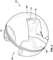
FIGS. 3-5 are a perspective views of a valve member of the valve ofFIG. 1 ; and -
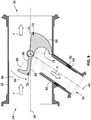
FIGS. 6-9 are cross sectional views of the valve ofFIG. 1 , showing several operational states thereof. - While the invention will be described in connection with certain preferred embodiments, there is no intent to limit it to those embodiments. On the contrary, the intent is to cover all alternatives, modifications and equivalents as included within the scope of the invention as defined by the appended claims.
- Turning now to the drawings,
FIGS. 1-9 illustrate an exemplary embodiment of a valve and valve system according to the teachings of the present invention. As will be explained in greater detail below, the valve and valve system shown and described herein advantageously overcomes existing problems in the art by providing a single valve with a single valve member which is operable to govern multiple bleed flows from a compressor of a turbine engine. The valve and valve system described herein achieves the foregoing with a reduced weight and size footprint and lower actuation force requirements. - Turning first to
FIG. 1 , the same illustrates an embodiment of avalve system 10 according to the teachings of the present invention.Valve system 10 includes avalve 20.Valve 20 has anouter housing 22 with aninlet 24, aprimary outlet 26 and asecondary outlet 28. Without restricting the applicability of the invention described herein from other applications,inlet 24 may be connected to a section of a compressor of a turbine engine. A compressor bleed flow may be received throughinlet 24 and selectively passed throughprimary outlet 26 for primary bleed flow functions such as pneumatic actuation of aircraft actuators. This bleed flow may also selectively pass throughsecondary outlet 28 for secondary bleed flow functions such as anti-icing. The foregoing functions are purely for example, and those of skill in the art will readily recognize thatprimary outlet 26 andsecondary outlet 28 may be connected to other portions of an aircraft to provide various functionality. - To achieve the foregoing, a valve member 30 (See e.g.
FIG. 2 ) is disposed within an interior ofhousing 22.Valve member 30 is operably coupled to avalve stem 32 which extends along anactuation axis 34 ofvalve 20. An actuator 36 (shown schematically herein) is coupled tovalve stem 32 to rotate the same aboutactuation axis 34 ultimately to govern a position ofvalve member 30 withinhousing 22. -
Actuator 36 may be any appropriate actuator designed for actuating a valve-type apparatus. As non-limiting examples,actuator 36 may be a linear, rotary, hydraulic, fueldraulic, or an electromagnetic-type actuator. - Still referring to
FIG. 1 ,inlet 24 andprimary outlet 26 are arranged along aprimary flow axis 38.Secondary outlet 28 is arranged along asecondary flow axis 40. As can be surmised from inspection ofFIG. 1 , as well as from reference toFIGS. 6-9 ,secondary flow axis 40 is transverse toprimary flow axis 38 at an angle θ which is less than 90°. Such an arrangement should be taken by way of example only, as it is entirely conceivable thatsecondary outlet 28 may be arranged along a secondary flow axis which is greater than or equal to 90° in other embodiments. - Turning now to
FIG. 2 ,valve 20 is shown in a cross-section to expose the internal componentry thereof.Valve member 30 and valve stem 32 are rotationally supported relative tohousing 22 by first andsecond bearings first housing cap 54 encloses first bearing 50 as shown, while asecond housing cap 56 enclosessecond bearing 52 as shown.Appropriate seals 58 are positioned between first andsecond housing caps second housing caps housing 22. Additionally, avalve stem seal 60 is provided around upper portion of valve stem 32 to prevent leakage at the area where valve stem 32 extends throughhousing 22 to engage actuator 36 (SeeFIG. 1 ). - As will be described in greater detail below,
valve member 30 also includes avalve member seal 72 which is disposed within a plane P that is transverse toactuation axis 34 as can be seen inFIG. 2 . Thisvalve member seal 72 provides a first seal arrangement ofvalve 20. - Turning now to
FIGS. 3-5 ,valve member 30 will be described in greater detail. With particular reference toFIG. 3 ,valve member 30 may be considered to be a hybrid valve member that includes portions thereof which are indicative of a butterfly valve-style valve member, but also portions which are indicative of a ball valve-style valve member. More specifically,valve member 30 includes afirst side 62 and asecond side 64.First side 62 includes aplanar portion 66 and ahemispherical portion 68. - As will be readily recognized by those of skill in the art,
planar portion 66 resembles a face of a butterfly valve element, whilehemispherical portion 68 resembles a portion of a ball valve member. Aseal groove 70 is interposed between first andsecond sides valve member seal 72 introduced above relative toFIG. 2 . - A slotted
aperture 74 is formed inhemispherical portion 68. Slottedaperture 74 is selectively alignable withsecondary outlet 28 as will be described in greater detail below relative toFIGS. 6-9 .Hemispherical portion 68 also includes apocket 76 which is generally adjacent a center axis ofvalve member 30.Pocket 76 advantageously provides a contoured surface which aids in smoothing out the flow contour in this region, as well as prevents an undesirable pressure drop or recirculation zone. - Turning now to
FIG. 4 ,hemispherical portion 68 also includes cut-outs valve member 30 as well as provide more flow area betweeninlet 24 andprimary outlet 26. With reference now toFIG. 5 ,valve member 30 also includes a receivingfeature 82 which extend partially throughsecond side 64 as well asfirst side 62. Receivingfeature 82 receives valve stem 32 (SeeFIG. 2 ). Anaperture 84 is also formed through receivingfeature 82 for receipt of a fastener to fixedly retainvalve member 30 relative tovalve stem 32. - As can also be seen in
FIG. 5 ,second side 64 includes aplanar surface 86 from which aflow feature 88 extends from. Thisflow feature 88 is positioned at a peripheral edge ofvalve member 30 and extends along a portion of the outer periphery thereof.Flow feature 88 acts as a dam or restriction to the flow whenvalve member 30 is an a partially or fully open position. This restriction acts to introduce or build up a higher pressureadjacent inlet 24 so that the flow is urged under this pressure build up towardssecondary outlet 28 in addition to flowing throughprimary outlet 26. It should be noted that the particular shape offlow feature 88 illustrated is for exemplary purposes only, and other shapes may be utilized. Further, flowfeature 88 may be entirely omitted in other embodiments. - Turning now to
FIGS. 6-9 , the various operational positions ofvalve member 30 will be described. Turning first toFIG. 6 ,valve member 30 is shown in a fully closed position. As a result, flow frominlet 24 toprimary outlet 26 as well as frominlet 24 tosecondary outlet 28 is prevented. As can also be seen in this view, the first seal arrangement provided byvalve member seal 72 is shown.Valve member seal 72 sealingly engages aninterior surface 96 ofhousing 22 in the fully closed position. Also shown inFIG. 6 is a second seal arrangement formed betweenvalve member 30 andsecondary outlet 28. This seal arrangement includes avalve shoe 90. - This
valve shoe 90 is biased by a biasingelement 92 into engagement withhemispherical portion 68 as shown. As can be seen inFIG. 6 , an end edge ofvalve shoe 90 which engageshemispherical portion 68 is tapered so that it generally assumes the same outer peripheral shape ofhemispherical portion 68. This close geometrical compliance combined with the biasing force provided by biasingelement 92 provides a seal betweenhemispherical portion 68 andvalve shoe 90 in the fully closed position. Anadditional seal 94 is providedadjacent biasing element 92 to prevent or minimize leakage at the interface betweenvalve shoe 90 andhousing 22. - Turning now to
FIG. 7 ,valve member 30 has been partially rotated inrotational direction 98 such that the seal formed betweenvalve member seal 72 andinterior surface 96 is broken. As a result, a flow F is permitted betweeninlet 24 andprimary outlet 26. As can be seen from inspection ofFIG. 7 , however,valve shoe 90 still fully engageshemispherical portion 68 such that flow frominlet 24 throughaperture 74 is prevented. - However, and referring now to
FIG. 8 , continued rotation ofvalve member 30 inrotational direction 98 will also open a flow path frominlet 24 throughaperture 74 andsecondary outlet 28. As a result, a flow F is permitted frominlet 20 to each of primary andsecondary outlets - Referring finally to
FIG. 9 , continued rotation ofvalve member 30 of in-rotational direction 98 will positionvalve member 30 such that the flow path betweeninlet 24 and primary andsecondary outlets valve member 30 presents a minimized flow restriction relative to the flow F frominlet 24 toprimary outlet 26 as well as frominlet 24 tosecondary outlet 28. - As can also be seen from inspection of
FIGS. 6-9 ,valve member 30 presents a generally minimized construction in both size and width while also achieving structural features of both a butterfly valve member as well as a ball valve member. This construction allows for a first and second seal arrangement as described above which permits for a reduction in actuation forces. As a result, actuator requirements of valve assembly 10 (SeeFIG. 1 ) are substantially reduced. This has the advantage of allowing for an overall reduced weight and size of the assembly. - The use of the terms "a" and "an" and "the" and similar referents in the context of describing the invention (especially in the context of the following claims) is to be construed to cover both the singular and the plural, unless otherwise indicated herein or clearly contradicted by context. The terms "comprising," "having," "including," and "containing" are to be construed as open-ended terms (i.e., meaning "including, but not limited to,") unless otherwise noted. Recitation of ranges of values herein are merely intended to serve as a shorthand method of referring individually to each separate value falling within the range, unless otherwise indicated herein, and each separate value is incorporated into the specification as if it were individually recited herein. All methods described herein can be performed in any suitable order unless otherwise indicated herein or otherwise clearly contradicted by context. The use of any and all examples, or exemplary language (e.g., "such as") provided herein, is intended merely to better illuminate the invention and does not pose a limitation on the scope of the invention unless otherwise claimed. No language in the specification should be construed as indicating any non-claimed element as essential to the practice of the invention.
- Preferred embodiments of this invention are described herein, including the best mode known to the inventors for carrying out the invention. Variations of those preferred embodiments may become apparent to those of ordinary skill in the art upon reading the foregoing description. The inventors expect skilled artisans to employ such variations as appropriate, and the inventors intend for the invention to be practiced otherwise than as specifically described herein.
Claims (14)
- A valve (20) comprising:a housing (22), the housing having an inlet (24), a primary outlet (26), and a secondary outlet (28); anda hybrid valve member (30) rotatably positioned within the housing, the hybrid valve member having a fully closed position wherein the hybrid valve member prevents flow between the inlet and the primary outlet and prevents flow between the inlet and the secondary outlet, the hybrid valve member including a planar portion (66) and a hemispherical portion (68) on a first side (62) thereof,wherein the planar portion faces the inlet in the fully closed position,wherein the hemispherical portion faces the secondary outlet in the fully closed position,wherein the hybrid valve member has a second side (64) in an opposed relationship to the first side,wherein the second side includes a planar portion (86), andwherein a seal groove (70) is interposed between the first and second sides.
- The valve of claim 1, wherein a seal (72) is positioned within the seal groove (70) and provides a radial seal between the hybrid valve member (30) and an interior surface (96) of the housing.
- The valve of claim 1, wherein an aperture (74) is formed through the hemispherical portion (68), such that the planar portion (66) of the first side (62) is exposed to a flow passing through the aperture.
- The valve of claim 3, wherein the aperture (74) is selectively alignable with the secondary outlet (28) such that a flow path extends between the inlet (24), the aperture, and the secondary outlet upon a rotation of the hybrid valve member (30) from the fully closed position.
- The valve of claim 4, wherein the aperture (74) is an elongated slot having an open side.
- The valve of claim 5, wherein the hemispherical portion (68) includes an internal pocket (76), the internal pocket offset from a center axis of the hybrid valve member.
- The valve of claim 2, further comprising a flow feature (88) extending away from the planar portion (86) of the second side (64).
- The valve of claim 7, wherein the flow feature (88) is positioned at an outer periphery of the hybrid valve member (30), the flow feature extending partially along the outer periphery of the hybrid valve member.
- The valve of claim 1, wherein the hemispherical portion (68) also faces the inlet (24) in the fully closed position.
- The valve of claim 1, further comprising a valve shoe (90), the valve shoe adjacent the secondary outlet (28) and biased against the hemispherical portion (68) to prevent a flow from the inlet (24) to the secondary outlet (28) in the fully closed position.
- A valve assembly, comprising:an actuator (36);the valve according to any one of claims 1 to 10, whereinthe actuator is mounted to the valve,the valve comprises a valve stem (32) connected to the hybrid valve member and extending through the housing such that a terminal end of the valve stem is connected to the actuator, the actuator operable to rotate the valve stem about an actuation axis (34) to thereby rotate the hybrid valve member within the housing, andat least a part of the hemispherical portion (68) faces the inlet (24) in the fully closed position of the valve member.
- The valve assembly of claim 11, wherein the hybrid valve member includes and the seal groove (70) receives a valve member seal (72) extending around an outer periphery of the hybrid valve member, the valve member seal arranged to radially seal against an internal surface (96) of the housing (22) such that the valve member seal prevents a flow between the inlet and the primary outlet in the fully closed position of the hybrid valve member.
- The valve assembly of claim 12, wherein the valve member seal (72) is disposed within a plane (P) which is transverse to the actuation axis.
- The valve assembly of claim 13, further comprising a valve shoe (90), the valve shoe (90) adjacent the secondary outlet (28) and biased against the hemispherical portion (68) to prevent a flow from the inlet to the secondary outlet in the fully closed position.
Applications Claiming Priority (2)
| Application Number | Priority Date | Filing Date | Title |
|---|---|---|---|
| US14/710,688 US9574499B2 (en) | 2015-05-13 | 2015-05-13 | Combined butterfly/ball valve |
| PCT/US2016/031208 WO2016182909A1 (en) | 2015-05-13 | 2016-05-06 | Combined butterfly/ball valve |
Publications (2)
| Publication Number | Publication Date |
|---|---|
| EP3295064A1 EP3295064A1 (en) | 2018-03-21 |
| EP3295064B1 true EP3295064B1 (en) | 2020-07-29 |
Family
ID=56024415
Family Applications (1)
| Application Number | Title | Priority Date | Filing Date |
|---|---|---|---|
| EP16723900.3A Active EP3295064B1 (en) | 2015-05-13 | 2016-05-06 | Combined butterfly/ball valve |
Country Status (4)
| Country | Link |
|---|---|
| US (1) | US9574499B2 (en) |
| EP (1) | EP3295064B1 (en) |
| CN (1) | CN107580653B (en) |
| WO (1) | WO2016182909A1 (en) |
Families Citing this family (11)
| Publication number | Priority date | Publication date | Assignee | Title |
|---|---|---|---|---|
| FR2998026B1 (en) * | 2012-11-12 | 2015-06-26 | Valeo Sys Controle Moteur Sas | VALVE, IN PARTICULAR FOR THERMAL MOTOR AIR CIRCUIT |
| US11313484B2 (en) * | 2016-01-29 | 2022-04-26 | Maxitrol Company | Multifunction valve |
| US10539038B2 (en) | 2017-01-04 | 2020-01-21 | Honeywell International Inc. | Aerodynamic torque reducing valve for use in a bleed air system |
| US9958071B1 (en) | 2017-02-15 | 2018-05-01 | Hamilton Sundstrand Corporation | High temperature shaft seal for bleed valve with roller bearings |
| JP6695816B2 (en) * | 2017-02-23 | 2020-05-20 | 株式会社豊田自動織機 | Flow path switching valve |
| CN108343515A (en) * | 2018-03-14 | 2018-07-31 | 李涛 | Temperature control throttle valve device |
| JP6737918B2 (en) * | 2018-03-14 | 2020-08-12 | タオ・リィTao LI | Temperature control throttle device |
| FR3080901B1 (en) * | 2018-05-04 | 2021-02-12 | Liebherr Aerospace Toulouse Sas | FLUID FLOW REGULATION VALVE AND AIR TAKING SYSTEM OF AN AIRCRAFT EQUIPPED WITH SUCH A VALVE |
| CN110469697B (en) * | 2019-08-27 | 2020-03-10 | 江苏恒弘阀门科技有限公司 | Gas-liquid dual-purpose multi-channel valve |
| WO2021080594A1 (en) * | 2019-10-25 | 2021-04-29 | Itt Manufacturing Enterprises Llc | Ridge seal segmented valve |
| CN111288181A (en) * | 2020-04-14 | 2020-06-16 | 九特阀门有限公司 | Two-way pressure hard sealing butterfly valve |
Family Cites Families (11)
| Publication number | Priority date | Publication date | Assignee | Title |
|---|---|---|---|---|
| DE2447173C2 (en) * | 1974-10-03 | 1986-03-20 | Hansen-BTR GmbH, 3320 Salzgitter | Filtrate drain cock |
| US4156439A (en) * | 1977-10-11 | 1979-05-29 | The Cessna Aircraft Company | Agriculture chemical spray valve |
| US4273157A (en) * | 1978-11-13 | 1981-06-16 | Tom Mcguane Industries, Inc. | Three way butterfly valve |
| US4465259A (en) * | 1981-03-16 | 1984-08-14 | Allen Richard J | Control valve |
| US5437307A (en) | 1994-06-27 | 1995-08-01 | Cianfrocca, Ii; Lawrence D. | Intake bypass valve |
| FR2741392B1 (en) * | 1995-11-22 | 1998-01-30 | Magneti Marelli France | CONDUCT THROTTLE BODY WITH EVOLUTIVE SHAPE ON ONE SIDE OF ITS AXIS AND EVOLUTIVE SHAPE THROTTLE BODY ON THE COMPLEMENTARY SIDE |
| US6135414A (en) | 1998-12-24 | 2000-10-24 | Whittaker Corporation | Ball valve apparatus |
| US6971632B2 (en) * | 2001-03-23 | 2005-12-06 | Borgwarner Inc. | Throttle plate wedge |
| ITTO20070013A1 (en) | 2007-01-09 | 2008-07-10 | Riccardo Ferrero | AIR-CONDITIONING PLANT, DISTRIBUTION UNIT AND DISTRIBUTION VALVE FOR THIS SYSTEM, AND METHOD FOR THERMAL CONDITIONING OF A BUILDING THROUGH THIS SYSTEM. |
| CN101074739A (en) * | 2007-06-19 | 2007-11-21 | 吴思思 | Draining three-way valve of washbasin |
| FR2919674B1 (en) | 2007-07-31 | 2009-10-02 | Renault Sas | DEVICE FOR ORIENTATION AND REGULATION OF EXHAUST GAS OF A HEAT ENGINE IN AN EXHAUST GAS RECIRCULATION CIRCUIT CALLED EGR TO AIR INTAKE |
-
2015
- 2015-05-13 US US14/710,688 patent/US9574499B2/en active Active
-
2016
- 2016-05-06 CN CN201680027435.2A patent/CN107580653B/en active Active
- 2016-05-06 WO PCT/US2016/031208 patent/WO2016182909A1/en not_active Ceased
- 2016-05-06 EP EP16723900.3A patent/EP3295064B1/en active Active
Non-Patent Citations (1)
| Title |
|---|
| None * |
Also Published As
| Publication number | Publication date |
|---|---|
| CN107580653A (en) | 2018-01-12 |
| US20160333795A1 (en) | 2016-11-17 |
| US9574499B2 (en) | 2017-02-21 |
| EP3295064A1 (en) | 2018-03-21 |
| CN107580653B (en) | 2020-03-06 |
| WO2016182909A1 (en) | 2016-11-17 |
Similar Documents
| Publication | Publication Date | Title |
|---|---|---|
| US9574499B2 (en) | Combined butterfly/ball valve | |
| US5465756A (en) | Butterfly valve plate for a pneumatic surge valve | |
| US11261799B2 (en) | Combined ball valve for compressor bleed air and methods | |
| CN101627188B (en) | Snap-action valve for exhaust system | |
| US7533659B2 (en) | Exhaust-gas recirculation valve | |
| CN103620190B (en) | For controlling the valving that the aerofluxus of internal combustion engine is flowed | |
| CN111720591A (en) | Distribution Valves and Refrigeration Systems | |
| JP5986564B2 (en) | Fluid valve | |
| CN104114922A (en) | Check valve with flexible membrane | |
| EP1473498A1 (en) | Valve | |
| US9097351B2 (en) | Flow control hemispherical wedge valve | |
| CN109373019B (en) | Check valve and compressor | |
| JP6239615B2 (en) | Engine control valve with improved seal | |
| EP3067597B1 (en) | Use of a fluid control valve | |
| US9915233B2 (en) | Internal combustion engine with supercharger | |
| CN108431394B (en) | Regulators for internal combustion engines | |
| CN217177481U (en) | Plug valve, refrigerant control device of motor vehicle air conditioner, motor vehicle air conditioner and motor vehicle | |
| JP4086495B2 (en) | Butterfly valve with constant flow rate filling function | |
| US9920845B2 (en) | Control valve | |
| CN105317538A (en) | Exhaust system with remote multi-valve exhaust valves | |
| US20110084226A1 (en) | Full straight-shaft sealing butterfly valve | |
| JP7391867B2 (en) | Improved regulating valve with integrated purge function | |
| CN110541938A (en) | butterfly valve | |
| KR20120017984A (en) | Valve unit | |
| CN117927686A (en) | Sealing valve of hydrogen fuel cell engine |
Legal Events
| Date | Code | Title | Description |
|---|---|---|---|
| STAA | Information on the status of an ep patent application or granted ep patent |
Free format text: STATUS: THE INTERNATIONAL PUBLICATION HAS BEEN MADE |
|
| PUAI | Public reference made under article 153(3) epc to a published international application that has entered the european phase |
Free format text: ORIGINAL CODE: 0009012 |
|
| STAA | Information on the status of an ep patent application or granted ep patent |
Free format text: STATUS: REQUEST FOR EXAMINATION WAS MADE |
|
| 17P | Request for examination filed |
Effective date: 20171102 |
|
| AK | Designated contracting states |
Kind code of ref document: A1 Designated state(s): AL AT BE BG CH CY CZ DE DK EE ES FI FR GB GR HR HU IE IS IT LI LT LU LV MC MK MT NL NO PL PT RO RS SE SI SK SM TR |
|
| AX | Request for extension of the european patent |
Extension state: BA ME |
|
| DAV | Request for validation of the european patent (deleted) | ||
| DAX | Request for extension of the european patent (deleted) | ||
| GRAP | Despatch of communication of intention to grant a patent |
Free format text: ORIGINAL CODE: EPIDOSNIGR1 |
|
| STAA | Information on the status of an ep patent application or granted ep patent |
Free format text: STATUS: GRANT OF PATENT IS INTENDED |
|
| INTG | Intention to grant announced |
Effective date: 20200403 |
|
| GRAS | Grant fee paid |
Free format text: ORIGINAL CODE: EPIDOSNIGR3 |
|
| GRAA | (expected) grant |
Free format text: ORIGINAL CODE: 0009210 |
|
| STAA | Information on the status of an ep patent application or granted ep patent |
Free format text: STATUS: THE PATENT HAS BEEN GRANTED |
|
| AK | Designated contracting states |
Kind code of ref document: B1 Designated state(s): AL AT BE BG CH CY CZ DE DK EE ES FI FR GB GR HR HU IE IS IT LI LT LU LV MC MK MT NL NO PL PT RO RS SE SI SK SM TR |
|
| REG | Reference to a national code |
Ref country code: CH Ref legal event code: EP |
|
| REG | Reference to a national code |
Ref country code: AT Ref legal event code: REF Ref document number: 1296198 Country of ref document: AT Kind code of ref document: T Effective date: 20200815 |
|
| REG | Reference to a national code |
Ref country code: IE Ref legal event code: FG4D |
|
| REG | Reference to a national code |
Ref country code: DE Ref legal event code: R096 Ref document number: 602016040800 Country of ref document: DE |
|
| REG | Reference to a national code |
Ref country code: LT Ref legal event code: MG4D |
|
| REG | Reference to a national code |
Ref country code: NL Ref legal event code: MP Effective date: 20200729 |
|
| REG | Reference to a national code |
Ref country code: AT Ref legal event code: MK05 Ref document number: 1296198 Country of ref document: AT Kind code of ref document: T Effective date: 20200729 |
|
| PG25 | Lapsed in a contracting state [announced via postgrant information from national office to epo] |
Ref country code: FI Free format text: LAPSE BECAUSE OF FAILURE TO SUBMIT A TRANSLATION OF THE DESCRIPTION OR TO PAY THE FEE WITHIN THE PRESCRIBED TIME-LIMIT Effective date: 20200729 Ref country code: SE Free format text: LAPSE BECAUSE OF FAILURE TO SUBMIT A TRANSLATION OF THE DESCRIPTION OR TO PAY THE FEE WITHIN THE PRESCRIBED TIME-LIMIT Effective date: 20200729 Ref country code: PT Free format text: LAPSE BECAUSE OF FAILURE TO SUBMIT A TRANSLATION OF THE DESCRIPTION OR TO PAY THE FEE WITHIN THE PRESCRIBED TIME-LIMIT Effective date: 20201130 Ref country code: AT Free format text: LAPSE BECAUSE OF FAILURE TO SUBMIT A TRANSLATION OF THE DESCRIPTION OR TO PAY THE FEE WITHIN THE PRESCRIBED TIME-LIMIT Effective date: 20200729 Ref country code: HR Free format text: LAPSE BECAUSE OF FAILURE TO SUBMIT A TRANSLATION OF THE DESCRIPTION OR TO PAY THE FEE WITHIN THE PRESCRIBED TIME-LIMIT Effective date: 20200729 Ref country code: LT Free format text: LAPSE BECAUSE OF FAILURE TO SUBMIT A TRANSLATION OF THE DESCRIPTION OR TO PAY THE FEE WITHIN THE PRESCRIBED TIME-LIMIT Effective date: 20200729 Ref country code: NO Free format text: LAPSE BECAUSE OF FAILURE TO SUBMIT A TRANSLATION OF THE DESCRIPTION OR TO PAY THE FEE WITHIN THE PRESCRIBED TIME-LIMIT Effective date: 20201029 Ref country code: ES Free format text: LAPSE BECAUSE OF FAILURE TO SUBMIT A TRANSLATION OF THE DESCRIPTION OR TO PAY THE FEE WITHIN THE PRESCRIBED TIME-LIMIT Effective date: 20200729 Ref country code: GR Free format text: LAPSE BECAUSE OF FAILURE TO SUBMIT A TRANSLATION OF THE DESCRIPTION OR TO PAY THE FEE WITHIN THE PRESCRIBED TIME-LIMIT Effective date: 20201030 Ref country code: BG Free format text: LAPSE BECAUSE OF FAILURE TO SUBMIT A TRANSLATION OF THE DESCRIPTION OR TO PAY THE FEE WITHIN THE PRESCRIBED TIME-LIMIT Effective date: 20201029 |
|
| PG25 | Lapsed in a contracting state [announced via postgrant information from national office to epo] |
Ref country code: PL Free format text: LAPSE BECAUSE OF FAILURE TO SUBMIT A TRANSLATION OF THE DESCRIPTION OR TO PAY THE FEE WITHIN THE PRESCRIBED TIME-LIMIT Effective date: 20200729 Ref country code: LV Free format text: LAPSE BECAUSE OF FAILURE TO SUBMIT A TRANSLATION OF THE DESCRIPTION OR TO PAY THE FEE WITHIN THE PRESCRIBED TIME-LIMIT Effective date: 20200729 Ref country code: RS Free format text: LAPSE BECAUSE OF FAILURE TO SUBMIT A TRANSLATION OF THE DESCRIPTION OR TO PAY THE FEE WITHIN THE PRESCRIBED TIME-LIMIT Effective date: 20200729 Ref country code: IS Free format text: LAPSE BECAUSE OF FAILURE TO SUBMIT A TRANSLATION OF THE DESCRIPTION OR TO PAY THE FEE WITHIN THE PRESCRIBED TIME-LIMIT Effective date: 20201129 |
|
| PG25 | Lapsed in a contracting state [announced via postgrant information from national office to epo] |
Ref country code: NL Free format text: LAPSE BECAUSE OF FAILURE TO SUBMIT A TRANSLATION OF THE DESCRIPTION OR TO PAY THE FEE WITHIN THE PRESCRIBED TIME-LIMIT Effective date: 20200729 |
|
| PG25 | Lapsed in a contracting state [announced via postgrant information from national office to epo] |
Ref country code: IT Free format text: LAPSE BECAUSE OF FAILURE TO SUBMIT A TRANSLATION OF THE DESCRIPTION OR TO PAY THE FEE WITHIN THE PRESCRIBED TIME-LIMIT Effective date: 20200729 Ref country code: EE Free format text: LAPSE BECAUSE OF FAILURE TO SUBMIT A TRANSLATION OF THE DESCRIPTION OR TO PAY THE FEE WITHIN THE PRESCRIBED TIME-LIMIT Effective date: 20200729 Ref country code: DK Free format text: LAPSE BECAUSE OF FAILURE TO SUBMIT A TRANSLATION OF THE DESCRIPTION OR TO PAY THE FEE WITHIN THE PRESCRIBED TIME-LIMIT Effective date: 20200729 Ref country code: CZ Free format text: LAPSE BECAUSE OF FAILURE TO SUBMIT A TRANSLATION OF THE DESCRIPTION OR TO PAY THE FEE WITHIN THE PRESCRIBED TIME-LIMIT Effective date: 20200729 Ref country code: RO Free format text: LAPSE BECAUSE OF FAILURE TO SUBMIT A TRANSLATION OF THE DESCRIPTION OR TO PAY THE FEE WITHIN THE PRESCRIBED TIME-LIMIT Effective date: 20200729 Ref country code: SM Free format text: LAPSE BECAUSE OF FAILURE TO SUBMIT A TRANSLATION OF THE DESCRIPTION OR TO PAY THE FEE WITHIN THE PRESCRIBED TIME-LIMIT Effective date: 20200729 |
|
| REG | Reference to a national code |
Ref country code: DE Ref legal event code: R097 Ref document number: 602016040800 Country of ref document: DE |
|
| PG25 | Lapsed in a contracting state [announced via postgrant information from national office to epo] |
Ref country code: AL Free format text: LAPSE BECAUSE OF FAILURE TO SUBMIT A TRANSLATION OF THE DESCRIPTION OR TO PAY THE FEE WITHIN THE PRESCRIBED TIME-LIMIT Effective date: 20200729 |
|
| PLBE | No opposition filed within time limit |
Free format text: ORIGINAL CODE: 0009261 |
|
| STAA | Information on the status of an ep patent application or granted ep patent |
Free format text: STATUS: NO OPPOSITION FILED WITHIN TIME LIMIT |
|
| PG25 | Lapsed in a contracting state [announced via postgrant information from national office to epo] |
Ref country code: SK Free format text: LAPSE BECAUSE OF FAILURE TO SUBMIT A TRANSLATION OF THE DESCRIPTION OR TO PAY THE FEE WITHIN THE PRESCRIBED TIME-LIMIT Effective date: 20200729 |
|
| 26N | No opposition filed |
Effective date: 20210430 |
|
| PG25 | Lapsed in a contracting state [announced via postgrant information from national office to epo] |
Ref country code: SI Free format text: LAPSE BECAUSE OF FAILURE TO SUBMIT A TRANSLATION OF THE DESCRIPTION OR TO PAY THE FEE WITHIN THE PRESCRIBED TIME-LIMIT Effective date: 20200729 |
|
| REG | Reference to a national code |
Ref country code: CH Ref legal event code: PL |
|
| GBPC | Gb: european patent ceased through non-payment of renewal fee |
Effective date: 20210506 |
|
| PG25 | Lapsed in a contracting state [announced via postgrant information from national office to epo] |
Ref country code: CH Free format text: LAPSE BECAUSE OF NON-PAYMENT OF DUE FEES Effective date: 20210531 Ref country code: MC Free format text: LAPSE BECAUSE OF FAILURE TO SUBMIT A TRANSLATION OF THE DESCRIPTION OR TO PAY THE FEE WITHIN THE PRESCRIBED TIME-LIMIT Effective date: 20200729 Ref country code: LI Free format text: LAPSE BECAUSE OF NON-PAYMENT OF DUE FEES Effective date: 20210531 Ref country code: LU Free format text: LAPSE BECAUSE OF NON-PAYMENT OF DUE FEES Effective date: 20210506 |
|
| REG | Reference to a national code |
Ref country code: BE Ref legal event code: MM Effective date: 20210531 |
|
| PG25 | Lapsed in a contracting state [announced via postgrant information from national office to epo] |
Ref country code: IE Free format text: LAPSE BECAUSE OF NON-PAYMENT OF DUE FEES Effective date: 20210506 Ref country code: GB Free format text: LAPSE BECAUSE OF NON-PAYMENT OF DUE FEES Effective date: 20210506 |
|
| PG25 | Lapsed in a contracting state [announced via postgrant information from national office to epo] |
Ref country code: FR Free format text: LAPSE BECAUSE OF NON-PAYMENT OF DUE FEES Effective date: 20210531 |
|
| PG25 | Lapsed in a contracting state [announced via postgrant information from national office to epo] |
Ref country code: BE Free format text: LAPSE BECAUSE OF NON-PAYMENT OF DUE FEES Effective date: 20210531 |
|
| PG25 | Lapsed in a contracting state [announced via postgrant information from national office to epo] |
Ref country code: HU Free format text: LAPSE BECAUSE OF FAILURE TO SUBMIT A TRANSLATION OF THE DESCRIPTION OR TO PAY THE FEE WITHIN THE PRESCRIBED TIME-LIMIT; INVALID AB INITIO Effective date: 20160506 |
|
| PG25 | Lapsed in a contracting state [announced via postgrant information from national office to epo] |
Ref country code: CY Free format text: LAPSE BECAUSE OF FAILURE TO SUBMIT A TRANSLATION OF THE DESCRIPTION OR TO PAY THE FEE WITHIN THE PRESCRIBED TIME-LIMIT Effective date: 20200729 |
|
| PG25 | Lapsed in a contracting state [announced via postgrant information from national office to epo] |
Ref country code: MK Free format text: LAPSE BECAUSE OF FAILURE TO SUBMIT A TRANSLATION OF THE DESCRIPTION OR TO PAY THE FEE WITHIN THE PRESCRIBED TIME-LIMIT Effective date: 20200729 |
|
| PG25 | Lapsed in a contracting state [announced via postgrant information from national office to epo] |
Ref country code: MT Free format text: LAPSE BECAUSE OF FAILURE TO SUBMIT A TRANSLATION OF THE DESCRIPTION OR TO PAY THE FEE WITHIN THE PRESCRIBED TIME-LIMIT Effective date: 20200729 |
|
| PGFP | Annual fee paid to national office [announced via postgrant information from national office to epo] |
Ref country code: DE Payment date: 20250529 Year of fee payment: 10 |
|
| PG25 | Lapsed in a contracting state [announced via postgrant information from national office to epo] |
Ref country code: TR Free format text: LAPSE BECAUSE OF FAILURE TO SUBMIT A TRANSLATION OF THE DESCRIPTION OR TO PAY THE FEE WITHIN THE PRESCRIBED TIME-LIMIT Effective date: 20200729 |