EP3294350B1 - Pressure-venting container for disinfection and storage of contact lenses - Google Patents
Pressure-venting container for disinfection and storage of contact lenses Download PDFInfo
- Publication number
- EP3294350B1 EP3294350B1 EP16724541.4A EP16724541A EP3294350B1 EP 3294350 B1 EP3294350 B1 EP 3294350B1 EP 16724541 A EP16724541 A EP 16724541A EP 3294350 B1 EP3294350 B1 EP 3294350B1
- Authority
- EP
- European Patent Office
- Prior art keywords
- cap
- lens
- container
- lens holder
- stem
- Prior art date
- Legal status (The legal status is an assumption and is not a legal conclusion. Google has not performed a legal analysis and makes no representation as to the accuracy of the status listed.)
- Active
Links
Images





Classifications
-
- A—HUMAN NECESSITIES
- A45—HAND OR TRAVELLING ARTICLES
- A45C—PURSES; LUGGAGE; HAND CARRIED BAGS
- A45C11/00—Receptacles for purposes not provided for in groups A45C1/00-A45C9/00
- A45C11/005—Contact lens cases
-
- A—HUMAN NECESSITIES
- A61—MEDICAL OR VETERINARY SCIENCE; HYGIENE
- A61L—METHODS OR APPARATUS FOR STERILISING MATERIALS OR OBJECTS IN GENERAL; DISINFECTION, STERILISATION OR DEODORISATION OF AIR; CHEMICAL ASPECTS OF BANDAGES, DRESSINGS, ABSORBENT PADS OR SURGICAL ARTICLES; MATERIALS FOR BANDAGES, DRESSINGS, ABSORBENT PADS OR SURGICAL ARTICLES
- A61L12/00—Methods or apparatus for disinfecting or sterilising contact lenses; Accessories therefor
- A61L12/08—Methods or apparatus for disinfecting or sterilising contact lenses; Accessories therefor using chemical substances
- A61L12/086—Container, accessories or devices therefor
-
- A—HUMAN NECESSITIES
- A45—HAND OR TRAVELLING ARTICLES
- A45C—PURSES; LUGGAGE; HAND CARRIED BAGS
- A45C13/00—Details; Accessories
- A45C13/02—Interior fittings; Means, e.g. inserts, for holding and packing articles
-
- B—PERFORMING OPERATIONS; TRANSPORTING
- B65—CONVEYING; PACKING; STORING; HANDLING THIN OR FILAMENTARY MATERIAL
- B65D—CONTAINERS FOR STORAGE OR TRANSPORT OF ARTICLES OR MATERIALS, e.g. BAGS, BARRELS, BOTTLES, BOXES, CANS, CARTONS, CRATES, DRUMS, JARS, TANKS, HOPPERS, FORWARDING CONTAINERS; ACCESSORIES, CLOSURES, OR FITTINGS THEREFOR; PACKAGING ELEMENTS; PACKAGES
- B65D25/00—Details of other kinds or types of rigid or semi-rigid containers
- B65D25/38—Devices for discharging contents
-
- B—PERFORMING OPERATIONS; TRANSPORTING
- B65—CONVEYING; PACKING; STORING; HANDLING THIN OR FILAMENTARY MATERIAL
- B65D—CONTAINERS FOR STORAGE OR TRANSPORT OF ARTICLES OR MATERIALS, e.g. BAGS, BARRELS, BOTTLES, BOXES, CANS, CARTONS, CRATES, DRUMS, JARS, TANKS, HOPPERS, FORWARDING CONTAINERS; ACCESSORIES, CLOSURES, OR FITTINGS THEREFOR; PACKAGING ELEMENTS; PACKAGES
- B65D47/00—Closures with filling and discharging, or with discharging, devices
- B65D47/04—Closures with discharging devices other than pumps
- B65D47/32—Closures with discharging devices other than pumps with means for venting
-
- B—PERFORMING OPERATIONS; TRANSPORTING
- B65—CONVEYING; PACKING; STORING; HANDLING THIN OR FILAMENTARY MATERIAL
- B65D—CONTAINERS FOR STORAGE OR TRANSPORT OF ARTICLES OR MATERIALS, e.g. BAGS, BARRELS, BOTTLES, BOXES, CANS, CARTONS, CRATES, DRUMS, JARS, TANKS, HOPPERS, FORWARDING CONTAINERS; ACCESSORIES, CLOSURES, OR FITTINGS THEREFOR; PACKAGING ELEMENTS; PACKAGES
- B65D51/00—Closures not otherwise provided for
- B65D51/24—Closures not otherwise provided for combined or co-operating with auxiliary devices for non-closing purposes
- B65D51/26—Closures not otherwise provided for combined or co-operating with auxiliary devices for non-closing purposes with means for keeping contents in position, e.g. resilient means
-
- B—PERFORMING OPERATIONS; TRANSPORTING
- B65—CONVEYING; PACKING; STORING; HANDLING THIN OR FILAMENTARY MATERIAL
- B65D—CONTAINERS FOR STORAGE OR TRANSPORT OF ARTICLES OR MATERIALS, e.g. BAGS, BARRELS, BOTTLES, BOXES, CANS, CARTONS, CRATES, DRUMS, JARS, TANKS, HOPPERS, FORWARDING CONTAINERS; ACCESSORIES, CLOSURES, OR FITTINGS THEREFOR; PACKAGING ELEMENTS; PACKAGES
- B65D81/00—Containers, packaging elements, or packages, for contents presenting particular transport or storage problems, or adapted to be used for non-packaging purposes after removal of contents
- B65D81/18—Containers, packaging elements, or packages, for contents presenting particular transport or storage problems, or adapted to be used for non-packaging purposes after removal of contents providing specific environment for contents, e.g. temperature above or below ambient
- B65D81/22—Containers, packaging elements, or packages, for contents presenting particular transport or storage problems, or adapted to be used for non-packaging purposes after removal of contents providing specific environment for contents, e.g. temperature above or below ambient in moist conditions or immersed in liquids
Definitions
- the present disclosure relates generally to the field of lens care, and more particularly to a container for disinfection and storage of contact lenses.
- Contact lens containers of various styles and functionality are utilized for storing, cleaning and/or disinfecting contact lenses.
- a hydrogen peroxide based lens care solution is used, wherein the contact lenses to be cleaned and/or disinfected are deposited in contact with the hydrogen peroxide solution for a certain period of time, in order that cleaning and/or disinfecting of the contact lenses can take place to a satisfactory extent.
- the contact lens containers utilized in such lens care systems typically comprise closable baskets, which open to receive the contact lenses to be cleaned and close to retain the lenses during treatment.
- the baskets are typically part of a contact lens holder component, which in turn can be connected to the cap of a contact lens container, for example via a stem or rib.
- the container cup Before the cap is placed onto the container cup, the container cup is dosed to a prescribed fill level with a hydrogen peroxide lens care solution.
- a catalyst tablet for example catalase which gives delayed release of catalase, can be added to the container cup before or after adding the hydrogen peroxide solution.
- the contact lens holder containing the lenses to be treated is immersed into the hydrogen peroxide solution in the container cup, and the container is closed by screwing the cap onto the container cup.
- the closure of the cap on the container cup may form a water-tight seal, to prevent leakage of the cleaning solution.
- the contact lenses are allowed to remain immersed in the solution for a period of time sufficient to complete the specified cleaning and/or disinfecting process.
- the oxygen produced from decomposition of hydrogen peroxide in the cleaning solution typically must be allowed to discharge from the container in some manner. Attempts to provide oxygen discharge exist, for example U.S. Patent No. 6,945,389 and U.S. Patent No. 8,757,367 , as well as U.S. Patent No. 6,000,534 , U.S. Patent No. 5,366,078 and publication US 2010/0233023 .
- the present disclosure relates to a lens care container for cleaning with cleaning solution.
- the lens care container includes a container cup defining an interior chamber accessible through an opening bounded by a rim having an outer diameter.
- the container cup is configured to hold the lens cleaning solution.
- the cap can be removably attachable to the container cup to cover the opening.
- the cap can further include a top panel, a coupling hub, and a collar having an inner diameter extending transversely from the top panel.
- the inner diameter can be configured to receive the container cup outer diameter.
- the top panel can include a pressure-release vent positioned within a deflection region.
- the coupling hub can define an interior gas vent path that extends from the top panel and bounded by an anti-rotation mechanism and at least one channel.
- the lens holder can include a stem having an anti-rotation mechanism that cooperates with the cap anti-rotation mechanism. The interaction between the stem anti-rotation mechanism and the cap anti-rotation mechanism can prevent rotation of the cap with respect to the lens holder.
- the lens holder can also include a seal which can sealably engage the cap pressure-release vent when the cap and lens holder are received within the container cup. During a disinfection process, a volume of gas generated from the cleaning solution passes through the at least one channel vent into the interior gas vent path to apply force against the deflection region and disengage the lens holder seal from the cap pressure-release vent to allow the gas to exit through the cap pressure-release vent.
- FIGS. 1-12 An example lens care container 10 for cleaning with cleaning solution is illustrated in FIGS. 1-12 .
- the container 10 includes a cup 100, a cap 20 and lens holder 30.
- the cap 20 can be a monolithic structure.
- the lens holder 30 can be a unitary structure.
- the lens holder 30 is illustrated to support a catalyst 40 disc.
- the illustrated container cup 100 defines an interior chamber accessible through a top opening bounded by a rim 105.
- the interior chamber holds a volume of cleaning and/or disinfection solution.
- the catalyst disc 40 interacts with the cleaning and/or disinfection solution when the cap 20 is inserted into the container cup 100.
- the container cup 100 rim 105 includes an outer diameter.
- a connection collar 101 extends from the rim 105 along the outer surface of the container cup 100.
- the connection collar 101 can have a securing surface, for example threading.
- the threaded connection collar surface 101 can have a channel 103 of unthreaded sections to provide a discharge channel for gas vented from the container during use, as will be described further below.
- the unthreaded channel 103 can extend generally linearly from the rim of the container cup 100 through the length of the threaded surface 101.
- the illustrated container 10 also includes a cap 20 that is removably attachable to the container cup 100 to cover the opening.
- the cap 20 includes a top panel 21, a coupling hub 26, and a collar 24.
- the illustrated collar 24 includes an inner diameter that extends transversely from the top panel 21. The inner diameter of the collar 24 is configured to receive the outer diameter of the collar 101 of the container cup 100.
- the top panel 21 includes a pressure-release vent 23 that is positioned within a deflection region 27.
- the deflection region 27 is defined by an annular geometry, for example a ring, of reduced thickness recessed away from the interior gas vent path 37.
- the coupling hub 26 defines an interior gas vent path 37 that extends from the top panel 21 and is bounded by an open distal end with an anti-rotation mechanism 42 and at least one channel vent 28.
- the cap pressure-release vent 23 includes an aperture extending through the top panel 21.
- the illustrated cap pressure-release vent 23 aperture can also include a funneled mouth 29 that leads from the inner surface of the cap 21.
- the illustrated lens holder 30 includes a stem 33 with an anti-rotation mechanism 38 that cooperates with the cap anti-rotation mechanism 42 to prevent rotation of the cap 20 with respect to the lens holder.
- the illustrated stem 33 also includes a seal 35 which can sealably engage the cap pressure-release vent 23 when the cap 20 and lens holder 30 are received within the container cup 100.
- the illustrated lens holder seal 35 can include a dome 39 extending from the stem 33, such that the dome sealably engages the inner circumference of the cap pressure-release vent 23 aperture.
- the illustrated lens holder seal 35 can also include a chamfered ring 41 surrounding the dome 39. The chamfered ring 41 sealably inserts into the funneled mouth 29 on the pressure-release valve 23.
- the illustrated lens holder stem 33 also includes at least two passageways 37.
- the at least two passageways 37 can be defined by at least two intersecting plates. As illustrated, the at least two intersecting plates support the lens holder seal 35.
- the at least two passageways in the stem 33 can be aligned with the interior gas vent path 37 in the hub 26 to allow free passage of the gas entering through the at least one channel vent 28.
- the cap anti-rotation mechanism 42 includes a male orientation key
- the lens holder anti-rotation mechanism 38 includes a female receiver to receive the cap anti-rotation mechanism orientation key.
- the cap coupling hub 26 can include a snap ring 31, for example a ridge, protruding within the interior gas vent path 37.
- the lens holder stem 33 can include a snap groove 43 to receive the snap ring 31.
- the lens holder 30 can also include a pair of repositionable lens baskets 32.
- the lens holder 30 can also include a neck 34 that extends between the pair of lens baskets 32 and the stem 33.
- the stem 33 also includes a radial flange 36 that extends between the neck 34 and the stem 33.
- the lens holder anti-rotation mechanism 38 can be defined within the radial flange 36.
- the cap top panel 21 can also include a rim wall 25 extending within the collar 24.
- the rim 105 of the container cup 100 is received between the cap collar 24 inner diameter and the rim wall 25.
Landscapes
- Mechanical Engineering (AREA)
- Engineering & Computer Science (AREA)
- Health & Medical Sciences (AREA)
- Animal Behavior & Ethology (AREA)
- Epidemiology (AREA)
- Life Sciences & Earth Sciences (AREA)
- Chemical & Material Sciences (AREA)
- General Health & Medical Sciences (AREA)
- Public Health (AREA)
- Veterinary Medicine (AREA)
- General Chemical & Material Sciences (AREA)
- Chemical Kinetics & Catalysis (AREA)
- Apparatus For Disinfection Or Sterilisation (AREA)
- Eyeglasses (AREA)
- Closures For Containers (AREA)
Description
- The present disclosure relates generally to the field of lens care, and more particularly to a container for disinfection and storage of contact lenses.
- Contact lens containers of various styles and functionality are utilized for storing, cleaning and/or disinfecting contact lenses. In some lens containment and care systems a hydrogen peroxide based lens care solution is used, wherein the contact lenses to be cleaned and/or disinfected are deposited in contact with the hydrogen peroxide solution for a certain period of time, in order that cleaning and/or disinfecting of the contact lenses can take place to a satisfactory extent. The contact lens containers utilized in such lens care systems typically comprise closable baskets, which open to receive the contact lenses to be cleaned and close to retain the lenses during treatment. The baskets are typically part of a contact lens holder component, which in turn can be connected to the cap of a contact lens container, for example via a stem or rib. Before the cap is placed onto the container cup, the container cup is dosed to a prescribed fill level with a hydrogen peroxide lens care solution. A catalyst tablet, for example catalase which gives delayed release of catalase, can be added to the container cup before or after adding the hydrogen peroxide solution. Finally, the contact lens holder containing the lenses to be treated is immersed into the hydrogen peroxide solution in the container cup, and the container is closed by screwing the cap onto the container cup.
- The closure of the cap on the container cup may form a water-tight seal, to prevent leakage of the cleaning solution. The contact lenses are allowed to remain immersed in the solution for a period of time sufficient to complete the specified cleaning and/or disinfecting process. The oxygen produced from decomposition of hydrogen peroxide in the cleaning solution typically must be allowed to discharge from the container in some manner. Attempts to provide oxygen discharge exist, for example
U.S. Patent No. 6,945,389 andU.S. Patent No. 8,757,367 , as well asU.S. Patent No. 6,000,534 ,U.S. Patent No. 5,366,078 and publicationUS 2010/0233023 . - Continued improvements to lens care systems for cleaning, disinfecting and storing contact lenses are desired. It is to the provision of improved lens care systems that the present invention is primarily directed.
- The present disclosure relates to a lens care container for cleaning with cleaning solution. The lens care container includes a container cup defining an interior chamber accessible through an opening bounded by a rim having an outer diameter. The container cup is configured to hold the lens cleaning solution. The cap can be removably attachable to the container cup to cover the opening. The cap can further include a top panel, a coupling hub, and a collar having an inner diameter extending transversely from the top panel. The inner diameter can be configured to receive the container cup outer diameter. The top panel can include a pressure-release vent positioned within a deflection region. The coupling hub can define an interior gas vent path that extends from the top panel and bounded by an anti-rotation mechanism and at least one channel. The lens holder can include a stem having an anti-rotation mechanism that cooperates with the cap anti-rotation mechanism. The interaction between the stem anti-rotation mechanism and the cap anti-rotation mechanism can prevent rotation of the cap with respect to the lens holder. The lens holder can also include a seal which can sealably engage the cap pressure-release vent when the cap and lens holder are received within the container cup. During a disinfection process, a volume of gas generated from the cleaning solution passes through the at least one channel vent into the interior gas vent path to apply force against the deflection region and disengage the lens holder seal from the cap pressure-release vent to allow the gas to exit through the cap pressure-release vent.
-
-
FIG. 1 is a perspective assembly view of a lens care system according to an example embodiment of the present disclosure. -
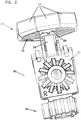
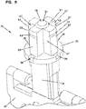
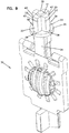
FIG. 2 is a perspective view of the contact lens holder component of the lens care system shown inFIG. 1 . -
FIG. 3 is a perspective view with partial cutaway of the cap component of the lens care system ofFIG 1 . -
FIG. 4 is a perspective cross sectional view of the cap component of the lens care system ofFIG 1 . -
FIG. 5A is a cross sectional view of the contact lens holder component ofFIG. 2 in a sealed state. -
FIG. 5B is a cross sectional view of the contact lens holder component ofFIG. 5A in an unsealed state. -
FIG. 6 . is an exploded view of the contact lens holder component ofFIG. 2 . -
FIG. 7 . is an underneath exploded view of the contact lens holder component ofFIG. 2 . -
FIG 8 . is a perspective cut away view of the stem and neck of the contact lens holder component ofFIG. 2 . -
FIG 9 . is a perspective view of the stem and neck of the contact lens holder component ofFIG. 2 . -
FIG. 10 is a perspective view of the cap removed from the stem and neck of the contact lens holder component ofFIG. 2 . -
FIG. 11 is a cross-sectional view of the cap ofFIG. 10 . -
FIG. 12 is a bottom view of the cap ofFIG. 10 . - The present disclosure may be understood more readily by reference to the following detailed description taken in connection with the accompanying drawing figures, which form a part of this disclosure. It is to be understood that this invention is not limited to the specific devices, methods, conditions or parameters described and/or shown herein, and that the terminology used herein is for the purpose of describing particular embodiments by way of example only and is not intended to be limiting of the claimed invention.
- An example
lens care container 10 for cleaning with cleaning solution is illustrated inFIGS. 1-12 . As illustrated, thecontainer 10 includes acup 100, acap 20 andlens holder 30. Thecap 20 can be a monolithic structure. Thelens holder 30 can be a unitary structure. Thelens holder 30 is illustrated to support acatalyst 40 disc. - The illustrated
container cup 100 defines an interior chamber accessible through a top opening bounded by arim 105. The interior chamber holds a volume of cleaning and/or disinfection solution. Thecatalyst disc 40 interacts with the cleaning and/or disinfection solution when thecap 20 is inserted into thecontainer cup 100. - The
container cup 100rim 105 includes an outer diameter. As illustrated, aconnection collar 101 extends from therim 105 along the outer surface of thecontainer cup 100. Theconnection collar 101 can have a securing surface, for example threading. As illustrated, the threadedconnection collar surface 101 can have achannel 103 of unthreaded sections to provide a discharge channel for gas vented from the container during use, as will be described further below. The unthreadedchannel 103 can extend generally linearly from the rim of thecontainer cup 100 through the length of the threadedsurface 101. - The illustrated
container 10 also includes acap 20 that is removably attachable to thecontainer cup 100 to cover the opening. Thecap 20 includes atop panel 21, acoupling hub 26, and acollar 24. The illustratedcollar 24 includes an inner diameter that extends transversely from thetop panel 21. The inner diameter of thecollar 24 is configured to receive the outer diameter of thecollar 101 of thecontainer cup 100. - The
top panel 21 includes a pressure-release vent 23 that is positioned within adeflection region 27. Thedeflection region 27 is defined by an annular geometry, for example a ring, of reduced thickness recessed away from the interiorgas vent path 37. - The
coupling hub 26 defines an interiorgas vent path 37 that extends from thetop panel 21 and is bounded by an open distal end with ananti-rotation mechanism 42 and at least onechannel vent 28. As illustrated, the cap pressure-release vent 23 includes an aperture extending through thetop panel 21. The illustrated cap pressure-release vent 23 aperture can also include a funneledmouth 29 that leads from the inner surface of thecap 21. - The illustrated
lens holder 30 includes astem 33 with ananti-rotation mechanism 38 that cooperates with thecap anti-rotation mechanism 42 to prevent rotation of thecap 20 with respect to the lens holder. The illustratedstem 33 also includes aseal 35 which can sealably engage the cap pressure-release vent 23 when thecap 20 andlens holder 30 are received within thecontainer cup 100. The illustratedlens holder seal 35 can include adome 39 extending from thestem 33, such that the dome sealably engages the inner circumference of the cap pressure-release vent 23 aperture. The illustratedlens holder seal 35 can also include a chamferedring 41 surrounding thedome 39. The chamferedring 41 sealably inserts into the funneledmouth 29 on the pressure-release valve 23. - As particularly depicted in
FIG. 5A , when thecatalyst disc 40 interacts with the cleaning and/or disinfection solution in thecontainer cup 100, a volume of gas passes through the channel vents 28 into the interiorgas vent path 37. This escaping gas applies an outwardly-directed force against thedeflection region 27 of thecap 21. As particularly depicted inFIG. 5B , this application of force flexes the captop surface 21 and disengages thelens holder seal 35 from the cap pressure-release vent 23 to allow the gas to exit through the cap pressure-release vent. - The illustrated lens holder stem 33 also includes at least two
passageways 37. The at least twopassageways 37 can be defined by at least two intersecting plates. As illustrated, the at least two intersecting plates support thelens holder seal 35. When thelens holder 30 is secured to thecap 20, the at least two passageways in thestem 33 can be aligned with the interiorgas vent path 37 in thehub 26 to allow free passage of the gas entering through the at least onechannel vent 28. - As illustrated, the
cap anti-rotation mechanism 42 includes a male orientation key, and the lensholder anti-rotation mechanism 38 includes a female receiver to receive the cap anti-rotation mechanism orientation key. - As illustrated, the
cap coupling hub 26 can include asnap ring 31, for example a ridge, protruding within the interiorgas vent path 37. The lens holder stem 33 can include asnap groove 43 to receive thesnap ring 31. - As illustrated, the
lens holder 30 can also include a pair ofrepositionable lens baskets 32. Thelens holder 30 can also include aneck 34 that extends between the pair oflens baskets 32 and thestem 33. Thestem 33 also includes aradial flange 36 that extends between theneck 34 and thestem 33. The lensholder anti-rotation mechanism 38 can be defined within theradial flange 36. - As illustrated, the cap
top panel 21 can also include arim wall 25 extending within thecollar 24. Therim 105 of thecontainer cup 100 is received between thecap collar 24 inner diameter and therim wall 25.
Claims (15)
- A lens care container for cleaning with disinfection solution, the lens care container comprising:a container cup (100) defining an interior chamber accessible through an opening bounded by a rim comprising an outer diameter, the container cup configured to hold the disinfection solution;a cap (20) removably attachable to the container cup (100) to cover the opening, the cap comprising a top panel (21), a coupling hub (26), and a collar (24) having an inner diameter extending transversely from the top panel, the inner diameter configured to receive the container cup outer diameter,; anda lens holder (30) comprising a stem (33);characterized in that:the top panel comprises a pressure-release vent (23) positioned within a deflection region (27), the coupling hub defining an interior gas vent path (37) extending from the top panel and bounded by an anti -rotation mechanism (42) and at least one channel vent (28) on the coupling hub;the stem (33) has an anti-rotation mechanism (38) that cooperates with the cap anti-rotation mechanism (42) to prevent rotation of the cap (20) with respect to the lens holder, and a seal (35) to sealably engage the cap pressure-release vent (23) when the cap and lens holder are received within the container cup (100);wherein said cap is configured to allow gas to exit through the cap pressure-release vent (23), when a volume of gas generated from the disinfection solution passes through the at least one channel vent (28) into the interior gas vent path (37) to apply force against the deflection region (27) and disengage the lens holder seal (35) from the cap pressure-release vent (23).
- The lens care container of claim 1, wherein the cap pressure-release vent (23) comprises an aperture extending through the top panel (21), and the lens holder seal (35) comprises a dome (39) extending from the stem (33), such that the dome sealably engages the inner circumference of the aperture.
- The lens care container of claim 2, wherein the lens holder seal (35) comprises a chamfered ring (41) surrounding the dome (39), and the cap aperture (23) comprises a funneled mouth facing the interior gas vent path (37), the funneled mouth receiving the dome and the chamfered ring.
- The lens care container of claim 1, wherein the lens holder stem (33) comprises at least two passageways aligned with the interior gas vent path (37) to allow free passage of gas entering through the at least one channel vent (28).
- The lens care container of claim 4, wherein the at least two passageways are defined by at least two intersecting plates.
- The lens care container of claim 5, wherein the at least two intersecting plates support the lens holder seal (35).
- The lens care container of claim 1, wherein the cap anti-rotation mechanism (42) comprises an orientation key, and the lens holder anti -rotation mechanism (38) comprises an orientation key receiver.
- The lens care container of claim 1, wherein the cap coupling hub (26) comprises a snap ring protruding within the interior gas vent path (37), and the lens holder stem (33) comprises a snap groove (43) to receive the snap ring.
- The lens care container of claim 8, wherein the snap ring comprises a ridge.
- The lens care container of claim 1, wherein the deflection region (27) is defined by an annular ring of reduced thickness recessed away from the interior gas vent path (37).
- The lens care container of claim 1, further comprising a catalyst carrier for carrying a catalyst (40).
- The lens care container of claim 1, wherein the lens holder (30) further comprises a pair of repositionable lens baskets (32).
- The lens care container of claim 12, wherein the lens holder (30) further comprises a neck (34) extending between the pair of lens baskets (32) and the stem (33).
- The lens care container of claim 12, wherein the stem (33) further comprises a radial flange (36) extending between the neck (34) and the stem (33), the lens holder anti-rotation mechanism (38) being defined within the radial flange.
- The lens care container of claim 1, wherein the cap top panel (21) further comprises a rim wall (25) extending within the collar (24), the rim of the container cup (100) being received between the cap collar and the cap rim wall.
Applications Claiming Priority (2)
| Application Number | Priority Date | Filing Date | Title |
|---|---|---|---|
| US14/707,097 US9532632B2 (en) | 2015-05-08 | 2015-05-08 | Pressure-venting container for disinfection and storage of contact lenses |
| PCT/US2016/031026 WO2016182854A1 (en) | 2015-05-08 | 2016-05-05 | Pressure-venting container for disinfection and storage of contact lenses |
Publications (2)
| Publication Number | Publication Date |
|---|---|
| EP3294350A1 EP3294350A1 (en) | 2018-03-21 |
| EP3294350B1 true EP3294350B1 (en) | 2019-12-04 |
Family
ID=56069242
Family Applications (1)
| Application Number | Title | Priority Date | Filing Date |
|---|---|---|---|
| EP16724541.4A Active EP3294350B1 (en) | 2015-05-08 | 2016-05-05 | Pressure-venting container for disinfection and storage of contact lenses |
Country Status (6)
| Country | Link |
|---|---|
| US (3) | US9532632B2 (en) |
| EP (1) | EP3294350B1 (en) |
| JP (1) | JP6385594B2 (en) |
| CN (1) | CN107995850B (en) |
| HU (1) | HUE048010T2 (en) |
| WO (1) | WO2016182854A1 (en) |
Families Citing this family (4)
| Publication number | Priority date | Publication date | Assignee | Title |
|---|---|---|---|---|
| US9532632B2 (en) | 2015-05-08 | 2017-01-03 | Better Vision Solutions LLC | Pressure-venting container for disinfection and storage of contact lenses |
| US11717591B2 (en) | 2018-11-29 | 2023-08-08 | Better Vision Solutions LLC | Methods for disinfecting contact lenses with a manganese-coated disc, and related contact lens treatment systems |
| US12029823B2 (en) * | 2019-08-26 | 2024-07-09 | Menicon Co., Ltd. | Ocular device case and refill container used for the ocular device case |
| TWI910927B (en) * | 2024-11-22 | 2026-01-01 | 均賀科技股份有限公司 | Overflow-proof contact lens container |
Family Cites Families (20)
| Publication number | Priority date | Publication date | Assignee | Title |
|---|---|---|---|---|
| US4750610A (en) * | 1986-12-29 | 1988-06-14 | Ryder International Corporation | Lens case with pressure sensitive venting system |
| US4956156A (en) * | 1988-11-07 | 1990-09-11 | Ryder International Corporation | Pressure venting system for lens cases |
| US4996027A (en) * | 1989-04-07 | 1991-02-26 | Ciba Vision Corporation | Contact lens case having pressure venting gasket |
| DE69121726T2 (en) * | 1990-11-30 | 1997-01-23 | Ciba Vision Corp | VENTILATION SYSTEM OF A CONTAINER FOR CONTACT LENSES |
| US5250266A (en) * | 1990-11-30 | 1993-10-05 | Ciba Vision Corporation | Contact lens case venting system |
| JPH05115536A (en) * | 1991-10-25 | 1993-05-14 | Tome Sangyo Kk | Contact lens treating device and contact lens treating vessel used therefor |
| US5366078A (en) * | 1993-09-28 | 1994-11-22 | Bausch & Lomb Incorporated | Vented carrying case for contact lenses |
| US5558846A (en) * | 1994-12-05 | 1996-09-24 | Ciba Geigy Corporation | Apparatus for disinfecting contact lenses having improved vent means |
| US6000534A (en) * | 1996-08-16 | 1999-12-14 | Allergan Sales, Inc. | Contact lens disinfecting device and disinfection system |
| TWI226227B (en) | 2001-07-10 | 2005-01-11 | Novartis Ag | Contact lens container |
| GB0603986D0 (en) | 2006-02-28 | 2006-04-05 | Montford University De | Fibrous catalyst |
| BRPI0807726B1 (en) * | 2007-02-07 | 2019-07-02 | Atrion Medical Products, Inc. | CONTACT LENS CASE |
| GB0716620D0 (en) | 2007-08-25 | 2007-10-03 | Efflotreat Ltd | Fibrous catalyst |
| EP2185271B1 (en) | 2007-08-25 | 2016-10-12 | De Montfort University | Antimicrobial agent and/or catalyst for chemical reactions |
| JP4624400B2 (en) | 2007-11-19 | 2011-02-02 | 株式会社オートネットワーク技術研究所 | Electric wire protection method and electric wire protection device for vehicle |
| US8141699B2 (en) | 2008-02-07 | 2012-03-27 | Atrion Medical Products, Inc. | Contact lens case |
| US8329098B2 (en) | 2009-03-16 | 2012-12-11 | Atrion Medical Products, Inc. | Additive effect enhanced hydrogen peroxide disinfection method and apparatus |
| WO2012049323A1 (en) * | 2010-10-15 | 2012-04-19 | Albert Sturm | Container for a contact lens storage solution and cleaning and/or sterilizing device for contact lenses in a contact lens storage solution |
| JP6055418B2 (en) * | 2010-12-17 | 2016-12-27 | ノバルティス アーゲー | Pressure relief container for sterilization and storage of contact lenses and method of treating contact lenses |
| US9532632B2 (en) | 2015-05-08 | 2017-01-03 | Better Vision Solutions LLC | Pressure-venting container for disinfection and storage of contact lenses |
-
2015
- 2015-05-08 US US14/707,097 patent/US9532632B2/en active Active
-
2016
- 2016-05-05 CN CN201680026540.4A patent/CN107995850B/en active Active
- 2016-05-05 WO PCT/US2016/031026 patent/WO2016182854A1/en not_active Ceased
- 2016-05-05 HU HUE16724541A patent/HUE048010T2/en unknown
- 2016-05-05 EP EP16724541.4A patent/EP3294350B1/en active Active
- 2016-05-05 JP JP2017559117A patent/JP6385594B2/en active Active
- 2016-11-18 US US15/355,479 patent/US9974370B2/en active Active
-
2018
- 2018-04-25 US US15/962,338 patent/US10271624B2/en active Active
Non-Patent Citations (1)
| Title |
|---|
| None * |
Also Published As
| Publication number | Publication date |
|---|---|
| US10271624B2 (en) | 2019-04-30 |
| US20160324287A1 (en) | 2016-11-10 |
| JP2018515238A (en) | 2018-06-14 |
| CN107995850B (en) | 2019-06-28 |
| US20180235336A1 (en) | 2018-08-23 |
| EP3294350A1 (en) | 2018-03-21 |
| WO2016182854A1 (en) | 2016-11-17 |
| US9532632B2 (en) | 2017-01-03 |
| JP6385594B2 (en) | 2018-09-05 |
| CN107995850A (en) | 2018-05-04 |
| US20170065046A1 (en) | 2017-03-09 |
| US9974370B2 (en) | 2018-05-22 |
| HUE048010T2 (en) | 2020-05-28 |
Similar Documents
| Publication | Publication Date | Title |
|---|---|---|
| US8757367B2 (en) | Pressure-venting container for disinfection and storage of contact lenses | |
| US10271624B2 (en) | Pressure-venting container | |
| US5250266A (en) | Contact lens case venting system | |
| US4750610A (en) | Lens case with pressure sensitive venting system | |
| JP3862786B2 (en) | Disinfection equipment | |
| EP2768739B1 (en) | Eyewash container | |
| JP3942665B2 (en) | Contact lens disinfection device with improved exhaust means | |
| JP2009201857A (en) | Container having lid | |
| EP0559775B1 (en) | Contact lens case venting system | |
| EP1712480B1 (en) | Cap element for a beverage can | |
| US6086823A (en) | Flat case for disinfecting contact lenses | |
| KR200473992Y1 (en) | Airtight Vacuum Lid | |
| KR200459530Y1 (en) | One bady type cap of connecte and separate | |
| JP2010001064A (en) | Container | |
| AU2020203812B2 (en) | Double packaging for object intended to remain sterile | |
| KR200487518Y1 (en) | Lid for cosmetic container having functional ball and cosmetic container comprising the same | |
| CA1098872A (en) | Contact lens capsule | |
| EP3462860B1 (en) | Container | |
| CN206624186U (en) | A kind of closure and silica gel ring | |
| KR20230171203A (en) | Baby silicone feeding container with support ring | |
| JPH0123974Y2 (en) | ||
| KR20160001469U (en) | Airtight lid for storage container for fermented food |
Legal Events
| Date | Code | Title | Description |
|---|---|---|---|
| STAA | Information on the status of an ep patent application or granted ep patent |
Free format text: STATUS: THE INTERNATIONAL PUBLICATION HAS BEEN MADE |
|
| PUAI | Public reference made under article 153(3) epc to a published international application that has entered the european phase |
Free format text: ORIGINAL CODE: 0009012 |
|
| STAA | Information on the status of an ep patent application or granted ep patent |
Free format text: STATUS: REQUEST FOR EXAMINATION WAS MADE |
|
| 17P | Request for examination filed |
Effective date: 20171122 |
|
| AK | Designated contracting states |
Kind code of ref document: A1 Designated state(s): AL AT BE BG CH CY CZ DE DK EE ES FI FR GB GR HR HU IE IS IT LI LT LU LV MC MK MT NL NO PL PT RO RS SE SI SK SM TR |
|
| AX | Request for extension of the european patent |
Extension state: BA ME |
|
| DAV | Request for validation of the european patent (deleted) | ||
| DAX | Request for extension of the european patent (deleted) | ||
| GRAP | Despatch of communication of intention to grant a patent |
Free format text: ORIGINAL CODE: EPIDOSNIGR1 |
|
| STAA | Information on the status of an ep patent application or granted ep patent |
Free format text: STATUS: GRANT OF PATENT IS INTENDED |
|
| INTG | Intention to grant announced |
Effective date: 20190627 |
|
| GRAS | Grant fee paid |
Free format text: ORIGINAL CODE: EPIDOSNIGR3 |
|
| GRAA | (expected) grant |
Free format text: ORIGINAL CODE: 0009210 |
|
| STAA | Information on the status of an ep patent application or granted ep patent |
Free format text: STATUS: THE PATENT HAS BEEN GRANTED |
|
| AK | Designated contracting states |
Kind code of ref document: B1 Designated state(s): AL AT BE BG CH CY CZ DE DK EE ES FI FR GB GR HR HU IE IS IT LI LT LU LV MC MK MT NL NO PL PT RO RS SE SI SK SM TR |
|
| REG | Reference to a national code |
Ref country code: GB Ref legal event code: FG4D |
|
| REG | Reference to a national code |
Ref country code: CH Ref legal event code: EP |
|
| REG | Reference to a national code |
Ref country code: AT Ref legal event code: REF Ref document number: 1208581 Country of ref document: AT Kind code of ref document: T Effective date: 20191215 |
|
| REG | Reference to a national code |
Ref country code: DE Ref legal event code: R096 Ref document number: 602016025530 Country of ref document: DE |
|
| REG | Reference to a national code |
Ref country code: IE Ref legal event code: FG4D |
|
| REG | Reference to a national code |
Ref country code: NL Ref legal event code: MP Effective date: 20191204 |
|
| REG | Reference to a national code |
Ref country code: LT Ref legal event code: MG4D |
|
| PG25 | Lapsed in a contracting state [announced via postgrant information from national office to epo] |
Ref country code: GR Free format text: LAPSE BECAUSE OF FAILURE TO SUBMIT A TRANSLATION OF THE DESCRIPTION OR TO PAY THE FEE WITHIN THE PRESCRIBED TIME-LIMIT Effective date: 20200305 Ref country code: NO Free format text: LAPSE BECAUSE OF FAILURE TO SUBMIT A TRANSLATION OF THE DESCRIPTION OR TO PAY THE FEE WITHIN THE PRESCRIBED TIME-LIMIT Effective date: 20200304 Ref country code: FI Free format text: LAPSE BECAUSE OF FAILURE TO SUBMIT A TRANSLATION OF THE DESCRIPTION OR TO PAY THE FEE WITHIN THE PRESCRIBED TIME-LIMIT Effective date: 20191204 Ref country code: BG Free format text: LAPSE BECAUSE OF FAILURE TO SUBMIT A TRANSLATION OF THE DESCRIPTION OR TO PAY THE FEE WITHIN THE PRESCRIBED TIME-LIMIT Effective date: 20200304 Ref country code: SE Free format text: LAPSE BECAUSE OF FAILURE TO SUBMIT A TRANSLATION OF THE DESCRIPTION OR TO PAY THE FEE WITHIN THE PRESCRIBED TIME-LIMIT Effective date: 20191204 Ref country code: LV Free format text: LAPSE BECAUSE OF FAILURE TO SUBMIT A TRANSLATION OF THE DESCRIPTION OR TO PAY THE FEE WITHIN THE PRESCRIBED TIME-LIMIT Effective date: 20191204 Ref country code: LT Free format text: LAPSE BECAUSE OF FAILURE TO SUBMIT A TRANSLATION OF THE DESCRIPTION OR TO PAY THE FEE WITHIN THE PRESCRIBED TIME-LIMIT Effective date: 20191204 |
|
| REG | Reference to a national code |
Ref country code: HU Ref legal event code: AG4A Ref document number: E048010 Country of ref document: HU |
|
| PG25 | Lapsed in a contracting state [announced via postgrant information from national office to epo] |
Ref country code: HR Free format text: LAPSE BECAUSE OF FAILURE TO SUBMIT A TRANSLATION OF THE DESCRIPTION OR TO PAY THE FEE WITHIN THE PRESCRIBED TIME-LIMIT Effective date: 20191204 Ref country code: RS Free format text: LAPSE BECAUSE OF FAILURE TO SUBMIT A TRANSLATION OF THE DESCRIPTION OR TO PAY THE FEE WITHIN THE PRESCRIBED TIME-LIMIT Effective date: 20191204 |
|
| PG25 | Lapsed in a contracting state [announced via postgrant information from national office to epo] |
Ref country code: AL Free format text: LAPSE BECAUSE OF FAILURE TO SUBMIT A TRANSLATION OF THE DESCRIPTION OR TO PAY THE FEE WITHIN THE PRESCRIBED TIME-LIMIT Effective date: 20191204 |
|
| PG25 | Lapsed in a contracting state [announced via postgrant information from national office to epo] |
Ref country code: NL Free format text: LAPSE BECAUSE OF FAILURE TO SUBMIT A TRANSLATION OF THE DESCRIPTION OR TO PAY THE FEE WITHIN THE PRESCRIBED TIME-LIMIT Effective date: 20191204 Ref country code: ES Free format text: LAPSE BECAUSE OF FAILURE TO SUBMIT A TRANSLATION OF THE DESCRIPTION OR TO PAY THE FEE WITHIN THE PRESCRIBED TIME-LIMIT Effective date: 20191204 Ref country code: PT Free format text: LAPSE BECAUSE OF FAILURE TO SUBMIT A TRANSLATION OF THE DESCRIPTION OR TO PAY THE FEE WITHIN THE PRESCRIBED TIME-LIMIT Effective date: 20200429 Ref country code: EE Free format text: LAPSE BECAUSE OF FAILURE TO SUBMIT A TRANSLATION OF THE DESCRIPTION OR TO PAY THE FEE WITHIN THE PRESCRIBED TIME-LIMIT Effective date: 20191204 Ref country code: CZ Free format text: LAPSE BECAUSE OF FAILURE TO SUBMIT A TRANSLATION OF THE DESCRIPTION OR TO PAY THE FEE WITHIN THE PRESCRIBED TIME-LIMIT Effective date: 20191204 Ref country code: RO Free format text: LAPSE BECAUSE OF FAILURE TO SUBMIT A TRANSLATION OF THE DESCRIPTION OR TO PAY THE FEE WITHIN THE PRESCRIBED TIME-LIMIT Effective date: 20191204 |
|
| PG25 | Lapsed in a contracting state [announced via postgrant information from national office to epo] |
Ref country code: SM Free format text: LAPSE BECAUSE OF FAILURE TO SUBMIT A TRANSLATION OF THE DESCRIPTION OR TO PAY THE FEE WITHIN THE PRESCRIBED TIME-LIMIT Effective date: 20191204 Ref country code: IS Free format text: LAPSE BECAUSE OF FAILURE TO SUBMIT A TRANSLATION OF THE DESCRIPTION OR TO PAY THE FEE WITHIN THE PRESCRIBED TIME-LIMIT Effective date: 20200404 Ref country code: SK Free format text: LAPSE BECAUSE OF FAILURE TO SUBMIT A TRANSLATION OF THE DESCRIPTION OR TO PAY THE FEE WITHIN THE PRESCRIBED TIME-LIMIT Effective date: 20191204 |
|
| REG | Reference to a national code |
Ref country code: DE Ref legal event code: R097 Ref document number: 602016025530 Country of ref document: DE |
|
| REG | Reference to a national code |
Ref country code: AT Ref legal event code: MK05 Ref document number: 1208581 Country of ref document: AT Kind code of ref document: T Effective date: 20191204 |
|
| PLBE | No opposition filed within time limit |
Free format text: ORIGINAL CODE: 0009261 |
|
| STAA | Information on the status of an ep patent application or granted ep patent |
Free format text: STATUS: NO OPPOSITION FILED WITHIN TIME LIMIT |
|
| PG25 | Lapsed in a contracting state [announced via postgrant information from national office to epo] |
Ref country code: DK Free format text: LAPSE BECAUSE OF FAILURE TO SUBMIT A TRANSLATION OF THE DESCRIPTION OR TO PAY THE FEE WITHIN THE PRESCRIBED TIME-LIMIT Effective date: 20191204 |
|
| 26N | No opposition filed |
Effective date: 20200907 |
|
| PG25 | Lapsed in a contracting state [announced via postgrant information from national office to epo] |
Ref country code: AT Free format text: LAPSE BECAUSE OF FAILURE TO SUBMIT A TRANSLATION OF THE DESCRIPTION OR TO PAY THE FEE WITHIN THE PRESCRIBED TIME-LIMIT Effective date: 20191204 Ref country code: PL Free format text: LAPSE BECAUSE OF FAILURE TO SUBMIT A TRANSLATION OF THE DESCRIPTION OR TO PAY THE FEE WITHIN THE PRESCRIBED TIME-LIMIT Effective date: 20191204 Ref country code: SI Free format text: LAPSE BECAUSE OF FAILURE TO SUBMIT A TRANSLATION OF THE DESCRIPTION OR TO PAY THE FEE WITHIN THE PRESCRIBED TIME-LIMIT Effective date: 20191204 |
|
| PG25 | Lapsed in a contracting state [announced via postgrant information from national office to epo] |
Ref country code: MC Free format text: LAPSE BECAUSE OF FAILURE TO SUBMIT A TRANSLATION OF THE DESCRIPTION OR TO PAY THE FEE WITHIN THE PRESCRIBED TIME-LIMIT Effective date: 20191204 Ref country code: CH Free format text: LAPSE BECAUSE OF NON-PAYMENT OF DUE FEES Effective date: 20200531 Ref country code: LI Free format text: LAPSE BECAUSE OF NON-PAYMENT OF DUE FEES Effective date: 20200531 Ref country code: IT Free format text: LAPSE BECAUSE OF FAILURE TO SUBMIT A TRANSLATION OF THE DESCRIPTION OR TO PAY THE FEE WITHIN THE PRESCRIBED TIME-LIMIT Effective date: 20191204 |
|
| REG | Reference to a national code |
Ref country code: BE Ref legal event code: MM Effective date: 20200531 |
|
| PG25 | Lapsed in a contracting state [announced via postgrant information from national office to epo] |
Ref country code: LU Free format text: LAPSE BECAUSE OF NON-PAYMENT OF DUE FEES Effective date: 20200505 |
|
| PG25 | Lapsed in a contracting state [announced via postgrant information from national office to epo] |
Ref country code: FR Free format text: LAPSE BECAUSE OF NON-PAYMENT OF DUE FEES Effective date: 20200531 |
|
| PG25 | Lapsed in a contracting state [announced via postgrant information from national office to epo] |
Ref country code: BE Free format text: LAPSE BECAUSE OF NON-PAYMENT OF DUE FEES Effective date: 20200531 |
|
| PG25 | Lapsed in a contracting state [announced via postgrant information from national office to epo] |
Ref country code: TR Free format text: LAPSE BECAUSE OF FAILURE TO SUBMIT A TRANSLATION OF THE DESCRIPTION OR TO PAY THE FEE WITHIN THE PRESCRIBED TIME-LIMIT Effective date: 20191204 Ref country code: MT Free format text: LAPSE BECAUSE OF FAILURE TO SUBMIT A TRANSLATION OF THE DESCRIPTION OR TO PAY THE FEE WITHIN THE PRESCRIBED TIME-LIMIT Effective date: 20191204 Ref country code: CY Free format text: LAPSE BECAUSE OF FAILURE TO SUBMIT A TRANSLATION OF THE DESCRIPTION OR TO PAY THE FEE WITHIN THE PRESCRIBED TIME-LIMIT Effective date: 20191204 |
|
| PG25 | Lapsed in a contracting state [announced via postgrant information from national office to epo] |
Ref country code: MK Free format text: LAPSE BECAUSE OF FAILURE TO SUBMIT A TRANSLATION OF THE DESCRIPTION OR TO PAY THE FEE WITHIN THE PRESCRIBED TIME-LIMIT Effective date: 20191204 |
|
| P01 | Opt-out of the competence of the unified patent court (upc) registered |
Effective date: 20230515 |
|
| REG | Reference to a national code |
Ref country code: DE Ref legal event code: R082 Ref document number: 602016025530 Country of ref document: DE Representative=s name: 4IP GLEIMPETRI PATENT- UND RECHTSANWALTSPARTNE, DE |
|
| PGFP | Annual fee paid to national office [announced via postgrant information from national office to epo] |
Ref country code: GB Payment date: 20260312 Year of fee payment: 11 |
|
| PGFP | Annual fee paid to national office [announced via postgrant information from national office to epo] |
Ref country code: IE Payment date: 20260310 Year of fee payment: 11 |
|
| PGFP | Annual fee paid to national office [announced via postgrant information from national office to epo] |
Ref country code: HU Payment date: 20260410 Year of fee payment: 11 |
|
| PGFP | Annual fee paid to national office [announced via postgrant information from national office to epo] |
Ref country code: DE Payment date: 20260310 Year of fee payment: 11 |