EP3294117B1 - Automatic brain probe guidance system - Google Patents
Automatic brain probe guidance system Download PDFInfo
- Publication number
- EP3294117B1 EP3294117B1 EP16793310.0A EP16793310A EP3294117B1 EP 3294117 B1 EP3294117 B1 EP 3294117B1 EP 16793310 A EP16793310 A EP 16793310A EP 3294117 B1 EP3294117 B1 EP 3294117B1
- Authority
- EP
- European Patent Office
- Prior art keywords
- brain
- stn
- probe
- region
- insertion trajectory
- Prior art date
- Legal status (The legal status is an assumption and is not a legal conclusion. Google has not performed a legal analysis and makes no representation as to the accuracy of the status listed.)
- Active
Links
Images



Classifications
-
- A—HUMAN NECESSITIES
- A61—MEDICAL OR VETERINARY SCIENCE; HYGIENE
- A61N—ELECTROTHERAPY; MAGNETOTHERAPY; RADIATION THERAPY; ULTRASOUND THERAPY
- A61N1/00—Electrotherapy; Circuits therefor
- A61N1/02—Details
- A61N1/04—Electrodes
- A61N1/05—Electrodes for implantation or insertion into the body, e.g. heart electrode
- A61N1/0526—Head electrodes
- A61N1/0529—Electrodes for brain stimulation
- A61N1/0534—Electrodes for deep brain stimulation
-
- A—HUMAN NECESSITIES
- A61—MEDICAL OR VETERINARY SCIENCE; HYGIENE
- A61B—DIAGNOSIS; SURGERY; IDENTIFICATION
- A61B34/00—Computer-aided surgery; Manipulators or robots specially adapted for use in surgery
- A61B34/20—Surgical navigation systems; Devices for tracking or guiding surgical instruments, e.g. for frameless stereotaxis
-
- A—HUMAN NECESSITIES
- A61—MEDICAL OR VETERINARY SCIENCE; HYGIENE
- A61B—DIAGNOSIS; SURGERY; IDENTIFICATION
- A61B5/00—Measuring for diagnostic purposes; Identification of persons
- A61B5/24—Detecting, measuring or recording bioelectric or biomagnetic signals of the body or parts thereof
- A61B5/25—Bioelectric electrodes therefor
- A61B5/279—Bioelectric electrodes therefor specially adapted for particular uses
- A61B5/291—Bioelectric electrodes therefor specially adapted for particular uses for electroencephalography [EEG]
- A61B5/293—Invasive
-
- A—HUMAN NECESSITIES
- A61—MEDICAL OR VETERINARY SCIENCE; HYGIENE
- A61B—DIAGNOSIS; SURGERY; IDENTIFICATION
- A61B5/00—Measuring for diagnostic purposes; Identification of persons
- A61B5/24—Detecting, measuring or recording bioelectric or biomagnetic signals of the body or parts thereof
- A61B5/316—Modalities, i.e. specific diagnostic methods
- A61B5/369—Electroencephalography [EEG]
- A61B5/375—Electroencephalography [EEG] using biofeedback
-
- A—HUMAN NECESSITIES
- A61—MEDICAL OR VETERINARY SCIENCE; HYGIENE
- A61B—DIAGNOSIS; SURGERY; IDENTIFICATION
- A61B90/00—Instruments, implements or accessories specially adapted for surgery or diagnosis and not covered by any of the groups A61B1/00 - A61B50/00, e.g. for luxation treatment or for protecting wound edges
- A61B90/10—Instruments, implements or accessories specially adapted for surgery or diagnosis and not covered by any of the groups A61B1/00 - A61B50/00, e.g. for luxation treatment or for protecting wound edges for stereotaxic surgery, e.g. frame-based stereotaxis
- A61B90/11—Instruments, implements or accessories specially adapted for surgery or diagnosis and not covered by any of the groups A61B1/00 - A61B50/00, e.g. for luxation treatment or for protecting wound edges for stereotaxic surgery, e.g. frame-based stereotaxis with guides for needles or instruments, e.g. arcuate slides or ball joints
-
- G—PHYSICS
- G06—COMPUTING OR CALCULATING; COUNTING
- G06F—ELECTRIC DIGITAL DATA PROCESSING
- G06F18/00—Pattern recognition
- G06F18/20—Analysing
- G06F18/29—Graphical models, e.g. Bayesian networks
- G06F18/295—Markov models or related models, e.g. semi-Markov models; Markov random fields; Networks embedding Markov models
-
- A—HUMAN NECESSITIES
- A61—MEDICAL OR VETERINARY SCIENCE; HYGIENE
- A61B—DIAGNOSIS; SURGERY; IDENTIFICATION
- A61B17/00—Surgical instruments, devices or methods
- A61B2017/00017—Electrical control of surgical instruments
- A61B2017/00022—Sensing or detecting at the treatment site
-
- A—HUMAN NECESSITIES
- A61—MEDICAL OR VETERINARY SCIENCE; HYGIENE
- A61B—DIAGNOSIS; SURGERY; IDENTIFICATION
- A61B17/00—Surgical instruments, devices or methods
- A61B17/34—Trocars; Puncturing needles
- A61B17/3403—Needle locating or guiding means
- A61B2017/3405—Needle locating or guiding means using mechanical guide means
- A61B2017/3409—Needle locating or guiding means using mechanical guide means including needle or instrument drives
Definitions
- the disclosure is directed to an automatic brain-probe guidance systems. Specifically, the disclosure is directed to a real-time method and system for guiding a probe to the dorsolateral oscillatory region of the subthalamic nucleus in the brain of a subject in need thereof using closed stochastic electrophysiological feed back.
- Deep brain stimulation is a surgical procedure involving the implantation of a medical device called a macroelectrode (also referred to as a "lead”, “brain pacemaker”, “electrode” or “chronic electrode”), which sends electrical impulses to specific parts of the brain.
- DBS in select brain regions has provided noticeable therapeutic benefits for otherwise treatment-resistant movement and affective disorders such as chronic pain, Parkinson's disease, tremor, dystonia and depression. At present, the procedure is used only for patients whose symptoms cannot be adequately controlled with medications.
- DBS directly changes brain activity in a controlled manner, and its effects are reversible (unlike those of lesioning techniques).
- DBS uses the surgically implanted, battery-operated medical neurostimulator to deliver electrical stimulation to targeted areas in the brain that control movement, blocking the abnormal nerve signals that cause tremor and PD symptoms.
- the methods describe can further comprise assigning to each location (or hidden state) along the insertion trajectory a probability value illustrating the probability of each observation element per HMM state.
- the maximum likelihood estimate of the HMM state-transition and emission (the observation value) probability matrices can be estimated based, for example, on known (in other words, human expert defined) state sequences.
- the inferred HMM state sequence can be calculated as the most probable sequence beginning with the HMM in state 1 (before the STN) before the first observation (using for example, Viterbi algorithm).
- an automatic brain-probe guidance system (or any collection of systems or sub-systems that individually or jointly execute a set, or multiple sets, of instructions to perform one or more steps of the methods described herein) comprising: a brain probe having a proximal end and a distal end, the proximal end configured to record a neurophysiological response, and the distal end operably coupled to a driver; the driver, operably coupled to the brain probe; a signal processing module in communication with the brain probe and the driver; optionally a controller operably coupled to the driver; and a display, in communication with the signal processing module.
- the processor-readable medium can include a solid-state memory such as a memory card or other package that houses one or more non-volatile read-only memories.
- the processor-readable medium can be a random access memory or other volatile rewritable memory.
- the processor-readable medium can include a magneto-optical or optical medium, such as a disk or tapes or other storage device to capture neurophysiological response such as, for example, mean beta power spectral density (PSD) and/or maximum beta PSD and/or root mean square (RMS) of the beta oscillatory activity values, neuronal firing rate, local field potential or a combination of neurophysiological responses comprising one or more of the foregoing.
- PSD mean beta power spectral density
- RMS root mean square
- a digital file attachment to an e-mail or other self-contained information archive or set of archives may be considered a distribution medium that is equivalent to a tangible storage medium. Accordingly, the disclosure is considered to include any one or more of a processor-readable medium or a distribution medium and other equivalents and successor media, in which data or instructions may be stored.
- the set of executable instructions in the neurophysiological response processor can be further configured to: analyze the neurophysiological response within the beta frequency band range (e.g., between about 15 Hz to about 30 Hz) to determine a value of beta oscillatory activity (in other words, an observed value), wherein the plurality of observation element based on the recorded neurophysiological response is a mean beta power spectral density (PSD) and/or maximum beta PSD and/or root mean square (RMS) of the beta oscillatory activity values.
- PSD mean beta power spectral density
- RMS root mean square
- the set of executable instructions in the step-determining-processor used in the guidance systems described, as a part of the signal processing module can further be configured to assign to each of a plurality of locations (or hidden/partially observable states) along the insertion trajectory - a probability value.
- the locations or in other words, inferred/hidden or partially observable states can be the DLOR of the STN and/or the region of the insertion trajectory immediately before the STN and/or the region inside the nonoscillatory STN and/or the region of the STN immediately following the STN.
- the memory in the step-determining-processor (which in an embodiment, can be the same as the step-determining- processor) can further have stored thereon known reference (or inferred) values (or observed nodes for representation of HMM as DBN) for each of the plurality of observation elements for the locations (or hidden states) along the insertion trajectory, as well as, in an embodiment, for each of the plurality of observation elements for the region inside the substantia nigra (SNR).
- known reference (or inferred) values or observed nodes for representation of HMM as DBN
- the brain probe used in the guidance systems described herein can be, for example, a stimulating and or recording electrode.
- the guidance system can further comprise a macroelectrode, configured to provide deep brain stimulation.
- Stimulating electrophysiological response and/or recording electrophysiological evoked response in the systems and methods described herein can comprise stimulating, recording or both stimulating and recording signals differentially, single ended or both differentially and single ended.
- a differential sensing configuration can include a tip electrode used as the sensing electrode and a ring electrode used as a reference electrode. Typical tip-to-ring spacing can be approximately 10 mm but may be greater or less than 10 mm. Other differential sensing configurations using any type of available electrodes can be used.
- both the sensing electrode and the reference electrode can be positioned along a mapped site, such as within a brain region or along a nerve branch, such that both electrodes are subjected to change in electrical potential caused by an electrophysiological event in the brain, for example, that resulting from transitioning between various states along the insertion trajectory.
- single ended sensing electrode configurations can comprise a sensing electrode in contact with a region of interest, paired with a reference electrode placed away from the region of interest and is sought to be advanced to the region of interest, such that the reference electrode is not initially subjected to changes in electrical potential caused by electrophysiological events occurring at the site.
Landscapes
- Health & Medical Sciences (AREA)
- Life Sciences & Earth Sciences (AREA)
- Engineering & Computer Science (AREA)
- Surgery (AREA)
- Heart & Thoracic Surgery (AREA)
- Public Health (AREA)
- Biomedical Technology (AREA)
- Veterinary Medicine (AREA)
- Animal Behavior & Ethology (AREA)
- General Health & Medical Sciences (AREA)
- Medical Informatics (AREA)
- Molecular Biology (AREA)
- Psychology (AREA)
- Nuclear Medicine, Radiotherapy & Molecular Imaging (AREA)
- Physics & Mathematics (AREA)
- Pathology (AREA)
- Neurosurgery (AREA)
- Neurology (AREA)
- Biophysics (AREA)
- Radiology & Medical Imaging (AREA)
- Cardiology (AREA)
- Data Mining & Analysis (AREA)
- Theoretical Computer Science (AREA)
- Robotics (AREA)
- Psychiatry (AREA)
- Evolutionary Biology (AREA)
- Evolutionary Computation (AREA)
- General Engineering & Computer Science (AREA)
- General Physics & Mathematics (AREA)
- Artificial Intelligence (AREA)
- Computer Vision & Pattern Recognition (AREA)
- Bioinformatics & Computational Biology (AREA)
- Bioinformatics & Cheminformatics (AREA)
- Oral & Maxillofacial Surgery (AREA)
- Measurement And Recording Of Electrical Phenomena And Electrical Characteristics Of The Living Body (AREA)
- Electrotherapy Devices (AREA)
Description
- The disclosure is directed to an automatic brain-probe guidance systems. Specifically, the disclosure is directed to a real-time method and system for guiding a probe to the dorsolateral oscillatory region of the subthalamic nucleus in the brain of a subject in need thereof using closed stochastic electrophysiological feed back.
- Deep brain stimulation (DBS) is a surgical procedure involving the implantation of a medical device called a macroelectrode (also referred to as a "lead", "brain pacemaker", "electrode" or "chronic electrode"), which sends electrical impulses to specific parts of the brain. DBS in select brain regions has provided noticeable therapeutic benefits for otherwise treatment-resistant movement and affective disorders such as chronic pain, Parkinson's disease, tremor, dystonia and depression. At present, the procedure is used only for patients whose symptoms cannot be adequately controlled with medications. DBS directly changes brain activity in a controlled manner, and its effects are reversible (unlike those of lesioning techniques). DBS uses the surgically implanted, battery-operated medical neurostimulator to deliver electrical stimulation to targeted areas in the brain that control movement, blocking the abnormal nerve signals that cause tremor and PD symptoms.
- Before the procedure, a neurosurgeon uses magnetic resonance imaging (MRI) or computed tomography (CT) scanning to identify and locate the exact target within the brain. For treating movement disorders, these targets are areas that control 5 movement, such as the thalamus, subthalamic nucleus, and globus pallidus where electrical nerve signals generate the undesired symptoms.
- DBS systems typically consist of three components: the macroelectrode, the extension, and the neurostimulator. The macroelectrode - a thin, insulated wire - is inserted through a small opening in the skull and implanted in the brain. The tip of the electrode is positioned within the targeted brain area.
- The extension is an insulated wire that can then be passed under the skin of the head, neck, and shoulder, connecting the lead to the neurostimulator. The neurostimulator (the "battery pack") is the third component and is usually implanted under the skin near the collarbone. In some cases it may be implanted lower in the chest or under the skin over the abdomen.
- Once the system is in place, electrical impulses are sent from the neurostimulator up along the extension wire and the lead and into the brain. These impulses interfere with and block the electrical signals that cause the undesired symptoms. The person has the possibility to turn the DBS off if required.
- Accordingly, accurate and fast guidance of the macroelectrode, which is critical in order to improve the effectiveness of the installed macroelectrode. Thus, there is a need in the field to accurately pilot the macroelectrode to the target region in the most precise manner available.
-
US2011301665A1 describes microelectrode array devices, and methods of fabrication and use of the same, to provide highly localized and efficient electrical stimulation of a neurological target. The device includes multiple microelectrode elements arranged along an elongated probe shaft. The microelectrode elements are dimensioned and shaped so as to target individual neurons, groups of neurons, and neural tissue as may be located in an animal nervous system, such as deep within a human brain. -
US8792972 relates to mapping regions in the brain using electrophysiology in general, and in particular to a real-time method and system for mapping the dorsolateral oscillatory region of the subthalamic nucleus in the brain during surgery using a dynamic Bayesian network. - The invention is defined in the independent claim. Optional features are set out in the dependent claims. The methods disclosed herein do not form part of the claimed invention as such. However, they illustrate the functions and the intended use of the claimed system.
- Provided herein are embodiments of automatic brain-probe guidance systems.
- In an example provided herein is a method of automatically guiding a driver coupled brain probe to a region of interest in the brain of a subject in need thereof, comprising: based on a predetermined insertion trajectory, positioning the brain probe toward the region of interest, the brain probe having a proximal end and a distal end coupled to a driver; using a predetermined step size, translating the brain probe toward the region of interest; recording a neurophysiological response by the brain probe along the predetermined insertion trajectory; based on the recorded neurophysiological response by the brain probe, calculating a plurality of predetermined observation elements; constructing a Bayesian Network for each observation element; combining the plurality of Bayesian Networks constructed for each observation element thereby creating a Dynamic Bayesian Network including the plurality of the predetermined observation elements; based on the Dynamic Bayesian Network, constructing a factored Partially Observable Markov Decision Process, wherein the Partially Observable Markov Decision Process (POMDP) further comprises relations between the predetermined observation elements; based on the POMDP, determining a distance step to advance the brain probe along the insertion trajectory; using the driver, automatically advancing the brain probe toward the region of interest along the insertion trajectory; and repeating the step of determining the distance step and advancing the brain probe to the location of interest.
- In an embodiment, provided herein is an automatic brain-probe guidance system comprising: a brain probe having a proximal end and a distal end, the proximal end configured to record a neurophysiological response, and the distal end operably coupled to a driver; the driver, operably coupled to the brain probe; a processing module in communication with the brain probe and the driver; optionally a controller operably coupled to the driver; and a display, in communication with the processing module.
- The features of the automatic brain-probe guidance systems and methods relating thereto described herein, will become apparent from the following detailed description when read in conjunction with the drawings, which are exemplary, not limiting, and wherein like elements are numbered alike in several figures and in which:
-
FIG. 1 , is a simplified block diagram illustrating the use of an embodiment of the automatic brain-probe guidance systems; -
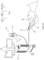
FIG. 2A , is a simplified pictorial illustration of an embodiment of the automatic brain-probe guidance system showing the probe outside of the STN and includes Table 1, while a simplified pictorial illustration of an embodiment of the automatic brain-probe guidance system showing the tool in the beginning of advancement within the STN including Table 2 is illustrated inFIG. 2B , and a simplified pictorial illustration of an embodiment of the automatic brain-probe guidance systems, showing the probe further advanced into the STN including Table 3 is illustrated inFIG. 2C ; and -
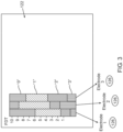
FIG. 3 illustrates a simplified pictorial of the graphic user interface shown on a display while using an embodiment of the automatic brain-probe guidance systems. - While the disclosure is amenable to various modifications and alternative forms, specifics thereof have been shown by way of example in the drawings and will be further described in detail hereinbelow. It should be understood, however, that the intention is not to limit the disclosure to the particular embodiments described. On the contrary, the intention is to cover all modifications, equivalents, and alternatives.
- The disclosure relates in one embodiment to automatic brain-probe guidance systems.
- The disclosure provides for an automatic guidance system for piloting a probe (e.g. MER) to a target region in the brain in order to treat a Parkinson Disease. Surgical treatment for advanced Parkinson's disease (PD) includes deep brain stimulation (DBS) of the subthalamic nucleus (STN), which has proven to be safe and beneficial over time. During surgery for implanting an STN DBS macroelectrode, microelectrode recording (MER) is often utilized to verify localization of the STN physiologically. To implant the macroelectrode successfully within the optimal location (probably the sensoridriver portion of the STN), accurate demarcation of the patient's STN (based on the MERs) is required. This includes derivation of the entry and exit points of the STN across the MER trajectory, as well as localization of the sensoridriver area within the STN.
- The STN can be divided into three (sensoridriver, limbic, and cognitive/associative) functional territories, each broadly involved in its respective basal ganglia-thalamocortical loop. The sensoridriver region of the STN is primarily located dorsolaterally, the same location that seems to provide optimal therapeutic benefit to patients undergoing STN DBS. Furthermore, it has been shown that local field potential and single unit (when averaged across patients) beta oscillatory activity is generated largely within the dorsolateral portion of the STN. This was also established according to the description of Applicant's prior patent
US 8,792,972 demonstrating there is correspondence between the dorsolateral oscillatory region (DLOR) and the sensoridriver region of the STN, and that beta-oscillatory activity could possibly predict the most effective contact for STN DBS. - In an embodiment, provided herein is an automated guidance system for piloting a brain probe (e.g., MER) to a region of interest in the brain by identifying subterritories within the STN and thus aiding the neurosurgeon in implanting the DBS macroelectrode in the optimal location or simply be used to estimate the transitions of a MER trajectory. Additionally provided is a real-time method for guiding a probe, such as MER within the brain and delimit the outer boundaries of the STN as well as an intra-STN (DLOR-ventral) boundary during surgery based on the beta range root mean square (RMS) and power spectral density (PSD) of the oscillatory neuronal activity recorded by the MERs, using a Hidden Markov Model (HMM) and Markov decision making models.
- The HMM or factorial HMM can be used, for example, offline to automatically detect the trajectory state transitions, or semi-online at the end of a trajectory during STN DBS surgery to help refine demarcation of the sensoridriver STN for macroelectrode implantation. Localization of the DLOR-ventral transition can aid the neurosurgeon in deciding which MER track to implant, when multiple electrodes are used for MER, and in implanting the macroelectrode at the optimal depth.
- Accordingly and in an example of using the systems described herein, provided herein is an example method of automatically guiding a driver coupled brain probe to a region of interest in the brain of a subject in need thereof, comprising: based on a predetermined insertion trajectory, positioning the brain probe toward the region of interest, the brain probe having a proximal end and a distal end coupled to a driver; using a predetermined step size, translating the brain probe toward the region of interest; recording a neurophysiological response by the brain probe along the predetermined insertion trajectory; based on the recorded neurophysiological response by the brain probe, calculating a plurality of predetermined observation elements; constructing a Bayesian Network for each observation element; combining the plurality of Bayesian Networks constructed for each observation element thereby creating a Dynamic Bayesian Network including the plurality of the predetermined observation elements; based on the Dynamic Bayesian Network, constructing a factored Partially Observable Markov Decision Process, wherein the Partially Observable Markov Decision Process (POMDP) further comprises relations between the predetermined observation elements; based on the POMDP, determining a distance step to advance the brain probe along the insertion trajectory; using the driver, automatically advancing the brain probe toward the region of interest along the insertion trajectory; and repeating the step of determining the distance step and advancing the brain probe to the location of interest.
- The number of steps to be taken and the size of each step can be determined by the signal processing module. In certain embodiments, the size of each step becomes smaller as the electrode approaches the estimated target region.
- The disclosure provides a real-time example method and system for guiding a probe to, for example, the dorsolateral oscillatory region of the subthalamic nucleus in the brain of a subject in need thereof using closed stochastic electrophysiological feedback loop optimization.
- As used herein the term "stochastic electrophysiological feed back loop" refer to operation with an adequately formulated objective function (for example, the expert determined reference for the location of the estimated location of a dorsolateral oscillatory region (DLOR) of the STN along the selected insertion trajectory), which compares a current observation element value, with a predetermined and/or desired target value and then calculates the difference or the "fit" between the two. The return-value of this objective function drives the evolutionary optimization process that generates the list of steps (responsible for insertion depth along the trajectory) of translational and/or rotational movements of the brain probe coupled to the driver and display.
- It is also appreciated that many kinds of probes may be used in connection with the systems and methods described herein. For example, EEG electrodes can be used, however it will be appreciated that any kind of medical electrodes comprising conducting and recording contacts, for obtaining various physiological (neurological and others) characteristics of a subject's brain may be used. These can be, for example, EMG, EKG, ERP, EP, VEP, SSEP medical electrodes or a combination comprising one or more of the foregoing electrodes. Other sensors may be similarly inserted, and used in conjunction with the systems and methods described herein, and can be for example; temperature sensors, (NIR e.g.,) oxygen sensors, current sensors, and the like. Accordingly, the systems for automatic brain-probe guidance described herein can further comprise a sensor array configured to provide additional information useful for surgical operation. The number and/or types of electrodes to be inserted remains to the discretion of the medical team in charge of the procedure. Adding more electrodes increases the chances a trajectory to go through the optimal target location, while at the same time also increases the chances causing damage along the trajectory, for example, going through a small blood vessel. Typically, the medical team chooses one to five electrodes to be inserted
- The region of interest for which the brain probe guidance systems and methods described herein are guided to, can be a sub-territory of the subthalamic nucleus (STN), for example, dorsolateral oscillatory region (DLOR) of the STN.
- STN target coordinates can be determined as a composite of indirect anterior commissure-posterior commissure atlas based location and/or using direct T2 magnetic resonance imaging (MRI), with the final STN position being verified using, for example, postoperative computerized tomography (CT) fused with the preoperative MRI and displayed using the display systems described and claimed.
- The neurophysiological response elements, or activity described herein, can be acquired via, for example, polyimide coated tungsten microelectrodes. For both the left and right hemispheres, a single trajectory can be selected, starting, for example, at 10 mm above the calculated target (e.g., center of the lateral STN, or the dorsolateral oscillatory region (DLOR) of the STN). Using a driver coupled to the MER, the electrodes (or brain probe) can be configured to be advanced in small discrete steps, toward the estimated region of interest (ROI). Step size can range, for example, from between about 50 µm and about 500 µm and be controlled to achieve optimal unit recording and identification of upper and lower borders of the STN. For example, shorter steps (e.g., ~ 100 µm) can be used when the electrode was advanced closer to the goal location of the STN. The systems and methods described, can be configured to provide, for example, a 2-second signal stabilization period after electrode movement cessation, with responses recorded for a minimum of, for example 5 seconds.
- In an embodiment, the neurophysiological response recorded by the brain probe used in the methods and systems for automatically guiding a brain probe to a region of interest described herein, can be neuronal firing rate, local field potential or a combination of neurophysiological responses comprising one or more of the foregoing, for example, by recording discharges from the advancing probe (or electrode) and analyzing the recording of the discharges within the beta frequency band range to determine an area of beta oscillatory activity. Beta (about 15-30 Hz) oscillatory activity in the subthalamic nucleus (STN) has been reported to greatly increase in Parkinson's Disease (PD) patients and may interfere with movement execution (Cassidy et al., 2002; Levy et al., 2002; Kuhn et al., 2004; 2005; Williams et al., 2003; 2005). Dopaminergic medications decrease beta activity (Levy et al., 2002) and deep brain stimulation (DBS) in the STN may alleviate PD symptoms by disrupting this oscillatory activity. Depth recordings in PD patients have demonstrated beta oscillatory local field potential (LFP) activity in STN (Levy et al., 2002; Kuhn et al., 2005). Beta oscillatory LFP activity in the STN has been shown to be coherent with cortical EEG and contralateral EMG (Williams et al., 2002; Marsden et al., 2001).
- Accordingly, the plurality of observation elements based on the recorded neurophysiological response used in the methods and systems for automatically guiding a brain probe to a region of interest described herein, can be power spectral density (PSD) and/or root mean square (RMS) of the beta oscillatory activity values.
- For the power spectral density (PSD) calculations, the raw signal can be rectified by the "absolute" operator and the mean subtracted, to expose the frequency band of interest (e.g, below about 70 Hz, for example, between about 15 Hz and about 30 Hz). The average PSD can be calculated in each location along the trajectory using, for example, Welch's method with about a 1 second Hamming window (with predetermined percentage overlap, e.g., 10%) and zero padding, resulting in a spectral resolution of ⅓ Hz. For each recording (or observation), the PSD can be normalized by the total power of the signal between 2-200 Hz. A plot of the PSD as a function of estimated distance to target (EDT) for the predetermined trajectory can constructed and displayed using the display means provided. In addition, PSD can be used as a marker for the DLOR of the STN based on the increased beta oscillatory activity.
- Likewise, entry and exit from the STN can be marked primarily by a dramatic increase and decrease in normalized RMS (NRMS). The NRMS and PSD of an example trajectory, as a function of estimated distance to target (EDT), can therefore be used to guide the advance of the brain probe along the selected trajectory.
- The number of the minimal Root Mean Square (RMS) values may be selected and normalized, for example five minimal RMS values may be utilized. Alternatively, a particular number of the first measured RMS values maybe utilized for normalization purposes. Normalization based on minimal RMS values can substantially facilitate noise reduction. At a minimum, the synthesized Dynamic Bayesian Network or HMM can be configured to distinguish between two regions (inferred states) inside the target region or outside the target region. In many cases, the Dynamic Bayesian Network can be trained to distinguish between more than two inferred regions (states).
- Training the Dynamic Bayesian Network or HMM can involve entering a statistically significant number of trajectory data reference cases comprising for each point along the insertion trajectory power spectral analysis values, where a human expert assigns to each point in the insertion trajectory, the correct region it is in. The Dynamic Bayesian Network can then study the statistical relations in the data of the reference cases, so that given a new case (trajectory) with only power spectral analysis values (e.g., mean and max Beta PSD) for points along the insertion trajectory, the Dynamic Bayesian Network can build a trajectory model assigning to each point (observation value) along the insertion trajectory the (hidden) state with the highest probability. Assigning the (hidden) state can take into account not only the power spectral analysis values recorded at the incremental stochastic step, but also the power spectral analysis values of part or all the points along the insertion trajectory.
- Moreover, the Dynamic Bayesian Network trajectory model serves in an embodiment, as a statistical reference based for analyzing new insertion trajectories and assigning the highest probability state to each location along the insertion trajectory.
- In order to estimate the state (e.g., the DLOR of the STN, the region of the insertion trajectory immediately before the STN, the region inside the nonoscillatory STN, or the region of the STN immediately following the STN), and whether the electrode is in one of the of the electrode at each step (depth) across the trajectory based, for example, on the recorded and analyzed observation elements (e.g., NRMS and PSD), a Hidden Markov Model (HMM), or, in another embodiment, factorial HMM can be used.
- A typical trajectory state sequence could go through all four states consecutively. However, since not all trajectories produce recordable oscillatory observations in the presumed DLOR of the STN, a trajectory could skip that state. In addition, a trajectory could terminate end in in the nonoscillatory STN (a MER trajectory that was terminated before exiting the STN).
- The step of positioning the brain probe toward the region of interest used in the methods and systems for automatically guiding a brain probe to a region of interest described herein, can be preceded by providing reference values for each of the plurality of observation elements for a statistically-significant number of locations along the insertion trajectories. In other words, the methods provided can further comprise an initial step of training the (e.g., factorial) HMM by providing reference data of a statistically-significant number of insertion trajectories, whereby states along each insertion trajectory are assigned observation elements' values (e.g., mean beta PSD, max beta PSD and NRMS of the beta oscillatory activity) by an expert to one of the states disclosed herein, as well as the observation elements associated with at least another region, for example, the region in the insertion trajectory within the substantia nigra (SNR).
- Identification of the transition to SNR area can be advantageous, because this area in the brain also exhibits significant neurophysiological signals (or emissions) that may be used as target for neurostimulation in the treatment of, for example, Parkinson's disease (PD).
- The methods describe, which can be implemented in the systems provided, can further comprise assigning to each location (or hidden state) along the insertion trajectory a probability value illustrating the probability of each observation element per HMM state. The maximum likelihood estimate of the HMM state-transition and emission (the observation value) probability matrices can be estimated based, for example, on known (in other words, human expert defined) state sequences. The inferred HMM state sequence can be calculated as the most probable sequence beginning with the HMM in state 1 (before the STN) before the first observation (using for example, Viterbi algorithm).
- The methods and systems for automatically guiding a brain probe to a region of interest described herein, can further comprise removing the inserted probe and inserting a macroelectrode into the region of interest, e.g., the DLOR of the STN, and proceeding to produce deep brain simulation (DBS) for treatment of a neurodegenerative disease and/or disorder, for example, a brain injury, a neurodegenerative disorder, stroke, epilepsy, or Parkinson's disease.
- The example methods for automatically guiding a brain probe to a region of interest described herein, can be implemented in the systems described herein. Accordingly, provided herein is an automatic brain-probe guidance system (or any collection of systems or sub-systems that individually or jointly execute a set, or multiple sets, of instructions to perform one or more steps of the methods described herein) comprising: a brain probe having a proximal end and a distal end, the proximal end configured to record a neurophysiological response, and the distal end operably coupled to a driver; the driver, operably coupled to the brain probe; a signal processing module in communication with the brain probe and the driver; optionally a controller operably coupled to the driver; and a display, in communication with the signal processing module.
- The term "coupled", including its various forms such as "operably coupled", "coupling" or "coupleable", refers to and comprises any direct or indirect, structural coupling, connection or attachment, or adaptation or capability for such a direct or indirect structural or operational coupling, connection or attachment, including integrally formed components and components which are coupled via or through another component or by the forming process (e.g., an electromagnetic field). Indirect coupling may involve coupling through an intermediary member or adhesive, or abutting and otherwise resting against, whether frictionally (e.g., against a housing) or by separate means without any physical connection.
- The term "signal processor" as used herein refers in an embodiment, to a power source, a pre-amplifier, an amplifier, an A/D and/or D/A converter, or a module or system comprising one or more of the foregoing.
- Likewise, the term "module" is understood to encompass a tangible entity, be that an entity that is physically constructed, specifically configured (e.g., hardwired), or temporarily (e.g., transitorily) configured (e.g., programmed) to operate in a specified manner or to perform part or all of any operation described herein. Considering examples in which modules are temporarily configured, each of the modules need not be instantiated at any one moment in time. For example, where the modules comprise a general-purpose hardware processor configured using software, the general-purpose hardware processor may be configured as respective different modules at different times. Software may accordingly configure a hardware processor, for example, to constitute a particular module at one instance of time and to constitute a different module at a different instance of time.
- Further, term "communicate" (and its derivatives e.g., a first component "communicates with" or "is in communication with" a second component) and grammatical variations thereof are used to indicate a structural, functional, mechanical, electrical, or optical relationship, or any combination thereof, between two or more components or elements. As such, the fact that one component is said to communicate with a second component is not intended to exclude the possibility that additional components can be present between, and/or operatively associated or engaged with, the first and second components. Furthermore, the term "electronic communication" means that one or more components of the multi-mode optoelectronic observation and sighting system with cross-platform integration capability described herein are in wired or wireless communication or internet communication so that electronic signals and information can be exchanged between the components.
- The signal processing module used in the guidance systems described herein comprises a neurophysiological response processor in communication with the brain probe, the processor comprising a memory having a processor-readable media thereon with a set of executable instructions thereon configured to: record a plurality of neurophysiological responses; and based on the recorded neurophysiological response by the brain probe, calculate a plurality of predetermined observation elements.
- The signal processing module comprises a step determining processor, in communication with the driver and neurophysiological response processor, the step determining processor comprising a memory having a processor-readable media thereon with a set of executable instructions configured to: construct a Bayesian Network for each observation element; combine the plurality of Bayesian Networks constructed for each observation element thereby creating a Dynamic Bayesian Network including the plurality of the predetermined observation elements; based on the Dynamic Bayesian Network, construct a factored Partially Observable Markov Decision Process, wherein the Partially Observable Markov Decision Process (POMDP) further comprises relations between the predetermined observation elements; and based on the POMDP, determine a distance step to advance the brain probe along the insertion trajectory.
- While the processor-readable medium can be a single medium, the term "processor-readable media" includes a single medium or multiple media, such as a centralized or distributed database, and/or associated caches and servers that store one or more sets of executable and other instructions. The term "processor-readable medium" may also include any medium that is capable of storing, encoding or carrying a set of instructions for execution by a processor or that cause a computer system or processor to perform any one or more of the methods or operations disclosed herein.
- For example, the processor-readable medium can include a solid-state memory such as a memory card or other package that houses one or more non-volatile read-only memories. Further, the processor-readable medium can be a random access memory or other volatile rewritable memory. Additionally, the processor-readable medium can include a magneto-optical or optical medium, such as a disk or tapes or other storage device to capture neurophysiological response such as, for example, mean beta power spectral density (PSD) and/or maximum beta PSD and/or root mean square (RMS) of the beta oscillatory activity values, neuronal firing rate, local field potential or a combination of neurophysiological responses comprising one or more of the foregoing.
- A digital file attachment to an e-mail or other self-contained information archive or set of archives may be considered a distribution medium that is equivalent to a tangible storage medium. Accordingly, the disclosure is considered to include any one or more of a processor-readable medium or a distribution medium and other equivalents and successor media, in which data or instructions may be stored.
- In an embodiment, the set of executable instructions in the neurophysiological response processor can be further configured to: analyze the neurophysiological response within the beta frequency band range (e.g., between about 15 Hz to about 30 Hz) to determine a value of beta oscillatory activity (in other words, an observed value), wherein the plurality of observation element based on the recorded neurophysiological response is a mean beta power spectral density (PSD) and/or maximum beta PSD and/or root mean square (RMS) of the beta oscillatory activity values. Each of which or a combination thereof, which can be used with the Dynamic Bayesian Network synthesized, to infer the hidden state at which the electrode is positioned and determine estimated distance to the target region of interest (ETD).
- Moreover, the set of executable instructions in the step-determining-processor used in the guidance systems described, as a part of the signal processing module, can further be configured to assign to each of a plurality of locations (or hidden/partially observable states) along the insertion trajectory - a probability value. The locations or in other words, inferred/hidden or partially observable states can be the DLOR of the STN and/or the region of the insertion trajectory immediately before the STN and/or the region inside the nonoscillatory STN and/or the region of the STN immediately following the STN.
- The memory in the step-determining-processor (which in an embodiment, can be the same as the step-determining- processor) can further have stored thereon known reference (or inferred) values (or observed nodes for representation of HMM as DBN) for each of the plurality of observation elements for the locations (or hidden states) along the insertion trajectory, as well as, in an embodiment, for each of the plurality of observation elements for the region inside the substantia nigra (SNR).
- The brain probe used in the guidance systems described herein can be, for example, a stimulating and or recording electrode. Moreover, the guidance system can further comprise a macroelectrode, configured to provide deep brain stimulation. Stimulating electrophysiological response and/or recording electrophysiological evoked response in the systems and methods described herein can comprise stimulating, recording or both stimulating and recording signals differentially, single ended or both differentially and single ended. For example, a differential sensing configuration can include a tip electrode used as the sensing electrode and a ring electrode used as a reference electrode. Typical tip-to-ring spacing can be approximately 10 mm but may be greater or less than 10 mm. Other differential sensing configurations using any type of available electrodes can be used. During differential sensing, both the sensing electrode and the reference electrode can be positioned along a mapped site, such as within a brain region or along a nerve branch, such that both electrodes are subjected to change in electrical potential caused by an electrophysiological event in the brain, for example, that resulting from transitioning between various states along the insertion trajectory.
- Likewise, single ended sensing electrode configurations can comprise a sensing electrode in contact with a region of interest, paired with a reference electrode placed away from the region of interest and is sought to be advanced to the region of interest, such that the reference electrode is not initially subjected to changes in electrical potential caused by electrophysiological events occurring at the site.
- Recording the observation elements described herein can be configured to be performed between two adjacent macro-contacts, for example a tip contact and a ring macro contact spaced between about 20 µm and about 500 µm from the tip contact (or electrode) by, for example, recording differential local field potential (LFP) between the two contacts, wherein one contact is a reference to the other.
- A more complete understanding of the components, processes, assemblies, and devices disclosed herein can be obtained by reference to the accompanying drawings. These figures (also referred to herein as "FIG.") are merely schematic representations (e.g., illustrations) based on convenience and the ease of demonstrating the present disclosure, and are, therefore, not intended to indicate relative size and dimensions of the devices or components thereof and/or to define or limit the scope of the exemplary embodiments. Although specific terms are used in the following description for the sake of clarity, these terms are intended to refer only to the particular structure of the embodiments selected for illustration in the drawings, and are not intended to define or limit the scope of the disclosure. In the drawings and the following description below, it is to be understood that like numeric designations refer to components of like function.
- Turning now to
FIG.s 1 , illustrating a simplified block diagram depicting the use of an automatic guidance system for guiding a brain probe to region of interest in the brain of a subject in need thereof. It is appreciated that the brain-probe can be, for example an electrode, such as a macroelectrode or a microelectrode. A plurality of electrode can be used simultaneously to record values of a plurality of insertion trajectories. As illustrated inFIG. 1 remote control 100 is provided, which can includetrigger button 102 that can be configured to be pressed in order to automatically guide the electrode. The trigger button enables adriver initiation 104 and thus provides for electrode translation along a predetermined insertion trajectory. For example, so long astrigger button 102 is pressed by the user, the driver automatically moves the electrode through the various states (or locations) within the brain of a subject in need thereof, located along thepredetermined insertion trajectory 106. The automatic movement (in other words, without human intervention of the distance or timing of insertion) of the electrode by the driver is achieved due to closed loop feedback provided in the signal processing module, using Partially Observable Markov Decision Process (POMDP). - Once the trigger button is released, the driver is stopped to provide time for the physician to verify accurate advancement of the electrode, and otherwise collect readings, thus utilizing the
trigger button 102 as a safety mechanism. - Previously, electrode advancement was not automatic and thus included the following steps: the electrode was advanced by discrete steps, the physician pressed on a button, thus initiated a single step movement of the electrode, waiting period for verifying the position of the electrode, re-definition of step size and further pressing on the button to advance the electrode by another single step. Therefore, using the methods described herein, implemented using the systems provided, surgery time can be reduced by at least 50%, since the electrode is automatically advanced using closed loop feedback and advancement step-size can automatically be re-defined and implemented. The different locations within the STN can be identified in real time, while advancing the electrode, obviating the need for performing a full scan of the area beforehand.
- Each time that an electrode is automatically advanced to a different site within the predetermined insertion trajectory, RMS and PSD are calculated 108 and the observed values for HMM output as DBN can be received by the signal processing module. The signal processing module is configured to calculate the subsequent step size using the closed loop feedback. Typically an inverse proportion is exhibited between the resulting NRMS values and determined step size, meaning the higher is the NRMS value, the lower is the step size, since higher resolution is required closer to the electrode's installation in the region of interest.
- The result of the closed loop feedback is demonstrated in blocks 110 - 116. In case the step size as determined is to be updated, as illustrated in
block 110, the signal processing module, being in electronic communication with the driver coupled to the electrode automatically updates following step size, as illustrated inblock 112. When step size does not have to be updated, as illustrated inblock 114, plots, results and recommendations to the user are shown on a display as illustrated inblock 116 and will be further described in detail (sere e.g.,FIG. 3 ). - 2A - 2C, which are respectively a simplified pictorial illustration of the automatic guidance system for guiding a brain-probe to a region of interest (ROI) in the brain showing the brain-probe outside of the STN and including Table 1 (2A), a simplified pictorial illustration of the automatic guidance system for guiding a brain-probe to a region of interest (ROI) in the brain showing the brain-probe in the beginning of advancement within the STN and including Table 2 (2B) and a simplified pictorial illustration of the automatic guidance system for guiding a brain-probe to a region of interest (ROI) in the brain showing the brain-probe further advanced into the STN and including Table 3 (2C).
- As illustrated in
FIG. 2A , the automatic guidance system for guiding a brain-probe to a target region in the brain can be utilized with NeuroOmega (AlphaOmega) or NeuroNav (Alphamega) system in the surgery room. The NeuroOmega or NeuroNav system is depicted byreference numeral 120,display 122 andremote control 100 are operably coupled thereto. Anelectrode 128 or plurality ofelectrodes 128 i can be operably coupled to aframe 124, which can be configured to engageelectrodes 126 relative to the skull of the patient and allow only longitudinal displacement ofelectrodes 126.Electrodes 126 can be operably coupled todriver 128, which automatically driveselectrode 126 upon pressing oftrigger button 102 onremote control 100. - Further, the tip of
electrode 126 is illustrated as positioned outside of the STN in this first operative orientation. As seen in Table 1, the Estimate distance to target (EDT) at this first operative orientation of insertion trajectory is, for example 10mm, with the HMM hidden or inferred state for the POMDM output being "0", indicating thatelectrode 126 is not positioned within any of the sub-territories of the STN and the step-size is determined to be 0.4mm for example. It is appreciated that any EDT value and step-size can be utilized and are within the scope of the disclosure provided. - As seen in
FIG. 2B , the automatic guidance system for guiding a brain-probe to a region of interest (ROI) in the brain is shown in a second orientation, whereelectrode 126 is positioned within the first region of the STN. As seen in Table 2, the Estimate distance to target (EDT) at this second operative orientation is 8.4 mm for example, with the HMM output being "1", indicating that theelectrode 126 is positioned within the first sub-territory of the STN and the step-size can now be automatically reduced to, for example, 0.2 mm. - As illustrated in
FIG. 2C , the automatic guidance system for guiding a brain-probe to a region of interest (ROI) in the brain is shown in a third operative orientation, whereelectrode 126 is positioned within the second region of the STN. As seen in Table 3, the Estimate distance to target (EDT) at this third operative orientation is, for example, 7 mm and the HMM hidden or inferred state output is "2", indicating thatelectrode 126 is positioned within the second sub-territory of the STN causing the step-size to now be automatically reduced to 0.1mm for example.Electrode 126 can be displaced along the insertion trajectory passing regions of interest such as 1. the DLOR of the STN; 2. the region in the insertion trajectory before the STN; 3. the region inside the nonoscillatory STN; or 4. the region in the insertion trajectory after the STN. Or, in addition, 5- the region in the insertion trajectory within the substantia nigra (SNR).Electrodes 126 can be displaced through the above mentioned regions automatically following single pressing ontrigger button 102 and the step size is automatically updated utilizing a closed loop feedback - a factored Partially Observable Markov Decision Process (POMDP). - Reference is made to
FIG. 3 , illustrating the graphic user interface shown on a display while using the automatic guidance system for guiding a brain-probe to a region of interest (ROI) in the brain. An exemplary user interface shown ondisplay 122 as a result of displacement of a plurality ofelectrodes 126 through the insertion trajectory. As seen inFIG. 3 , different regions in different EDT for each electrode can be depicted by different pattern. The user can then select the optimal location for macroelectrode implantation based on the results presented ondisplay 122. For example, as illustrated inFIG. 3 electrode 1 entered region "1" at 6 mm EDT, region "2" at 0mm EDT and region "3" at about -4mm EDT (indicating the probe need to be retracted.Electrode 2 entered region "1" at 9mm EDT, region "2" at 3mm EDT and region "3" at about - 1mm EDT.Electrode 3 entered region "1" at 8mm EDT, region "2" at 4mm EDT and region "3" at about -3mm EDT. The optimal trajectory can then be selected by the user and the macroelectrode can be implanted accordingly. - Detailed embodiments of the present technology are disclosed herein; however, it is to be understood that the disclosed embodiments are merely exemplary, which can be embodied in various forms. Therefore, specific structural and functional details disclosed herein are not to be interpreted as limiting but merely as a basis for the claims and as a representative basis for teaching one skilled in the art to variously employ the present technology in virtually any appropriately detailed structure. Further, the terms and phrases used herein are not intended to be limiting but rather to provide an understandable and enabling description.
- The terms "first," "second," and the like, herein do not denote any order, quantity, or importance, but rather are used to denote one element from another. The terms "a", "an" and "the" herein do not denote a limitation of quantity, and are to be construed to cover both the singular and the plural, unless otherwise indicated herein or clearly contradicted by context. The suffix "(s)" as used herein is intended to include both the singular and the plural of the term that it modifies, thereby including one or more of that term (e.g., the probe(s) includes one or more probe). Reference throughout the specification to "one embodiment", "another embodiment", "an embodiment", and so forth, means that a particular element (e.g., feature, structure, and/or characteristic) described in connection with the embodiment is included in at least one embodiment described herein, and may or may not be present in other embodiments. In addition, it is to be understood that the described elements may be combined in any suitable manner in the various embodiments.
- In addition, for the purposes of the present disclosure, directional or positional terms such as "top", "bottom", "upper," "lower," "side," "front," "frontal," "forward," "rear," "rearward," "back," "trailing," "above," "below," "left," "right," "horizontal," "vertical," "upward," "downward," "outer," "inner," "exterior," "interior," "intermediate," etc., are merely used for convenience in describing the various embodiments of the present disclosure.
- One or more components may be referred to herein as "configured to," "configured by," "configurable to," "operable/operative to," "adapted/adaptable," "able to," "conformable/conformed to," etc. The terms (e.g. "configured to") can generally encompass active-state components and/or inactive-state components and/or standby-state components, unless context requires otherwise.
- While in the foregoing specification the guidance systems for guiding a brain probe to a region of interest have been described in relation to certain preferred embodiments, and many details are set forth for purpose of illustration, it will be apparent to those skilled in the art that the disclosure can be susceptible to additional embodiments and that certain of the details described in this specification can be varied considerably without departing from the scope of the present invention as defined by the appended claims.
Claims (12)
- An automatic brain-probe guidance system comprising:a. a brain probe having a proximal end and a distal end, the proximal end configured to record a neurophysiological response, and the distal end operably coupled to a driver;b. the driver, operably coupled to the brain probe, wherein said driver is configured to automatically advance said brain probe using a step size;c. a processing module in communication with the brain probe and the driver, wherein said processing module is configured to calculate the step size using a factored Partially Observable Markov Decision Process (POMDP)-based closed loop feedback, comprising:(A) a neurophysiological response processor in communication with the brain probe, comprising a memory having a processor-readable medium thereon with a set of executable instructions thereon configured to (i) record a plurality of neurophysiological responses along an insertion trajectory of said brain probe; and (ii) based on the recorded neurophysiological responses by the brain probe, calculate a plurality of predetermined observation elements; and(B) a step determining processor, in communication with the driver and the neurophysiological response processor, the step determining processor comprising a memory having a processor-readable medium thereon with a set of executable instructions configured to:wherein said processing module is configured to update the step size according to result of said closed loop feedback; andi. construct a Bayesian Network for each observation element of said plurality of predetermined observation elements;ii. combine the plurality of Bayesian Networks constructed for each observation element thereby creating a Dynamic Bayesian Network including the plurality of the predetermined observation elements;iii. based on the Dynamic Bayesian Network, construct said factored POMDP, wherein the factored POMDP further comprises relations between the plurality of predetermined observation elements;iv. based on the factored POMDP, determine the step size to advance the brain probe along the insertion trajectory;d. a display, in communication with the processing module.
- The system of claim 1, wherein the neurophysiological response recorded by the brain probe is neuronal firing rate, local field potential or a combination of neurophysiological responses comprising one or more of the foregoing.
- The system of claim 2, wherein the set of executable instructions in the neurophysiological response processor is further configured to: analyze the neurophysiological response within the beta frequency band range to determine a value of beta oscillatory activity, wherein the plurality of predetermined observation elements based on the recorded neurophysiological response is a mean beta power spectral density (PSD) and/or maximum beta PSD and/or root mean square (RMS) and/or normalized RMS of the beta oscillatory activity values.
- The system of claim 3, wherein said plurality of predetermined observation elements comprise normalized root mean square (NRMS) or power spectral density (PSD) of the beta oscillatory activity values.
- The system of claim 3, wherein the set of executable instructions in the step determining processor is further configured to assign to each of a plurality of locations along the insertion trajectory a probability value, wherein the locations are the dorsolateral oscillatory region (DLOR) of the subthalamic nucleus (STN) and/or the region of the insertion trajectory immediately before the subthalamic nucleus (STN) and/or the region inside the nonoscillatory subthalamic nucleus (STN) and/or the region of the insertion trajectory immediately following the subthalamic nucleus (STN).
- The system of claim 5, wherein the memory in the step determining processor further has reference values for each of the plurality of predetermined observation elements for the locations along the insertion trajectory stored thereon.
- The system of claim 6, wherein the memory in the step determining processor further has reference values for each of the plurality of predetermined observation elements for the region inside the substantia nigra (SNR) stored thereon.
- The system of claim 1, wherein the brain probe is an electrode and wherein the system further comprises a macroelectrode, configured to provide deep brain stimulation.
- The system of claim 1, wherein said brain probe is configured to record the neurophysiological response by recording discharges by the brain probe along the predetermined insertion trajectory and analyzing the recording of the discharges within the beta frequency band range to determine an area of beta oscillatory activity.
- The system of claim 1, wherein said step determining processor stores reference values for each of the plurality of predetermined observation elements for a plurality of locations along the insertion trajectory.
- The system of claim 10, wherein the set of executable instructions in the step determining processor is further configured to assign to each of the plurality of locations along the insertion trajectory a probability value, wherein said locations comprise the dorsolateral oscillatory region (DLOR) of the subthalamic nucleus (STN) and/or the region of the insertion trajectory immediately before the subthalamic nucleus (STN) and/or the region inside the nonoscillatory subthalamic nucleus (STN) and/or the region of the insertion trajectory immediately following the subthalamic nucleus (STN).
- The system of claim 1, wherein said brain probe comprises a macroelectrode configured to provide deep brain stimulation.
Applications Claiming Priority (2)
| Application Number | Priority Date | Filing Date | Title |
|---|---|---|---|
| US201562159336P | 2015-05-10 | 2015-05-10 | |
| PCT/US2016/031448 WO2016182997A2 (en) | 2015-05-10 | 2016-05-09 | Automatic brain probe guidance system |
Publications (3)
| Publication Number | Publication Date |
|---|---|
| EP3294117A2 EP3294117A2 (en) | 2018-03-21 |
| EP3294117A4 EP3294117A4 (en) | 2019-01-09 |
| EP3294117B1 true EP3294117B1 (en) | 2025-07-02 |
Family
ID=57249083
Family Applications (1)
| Application Number | Title | Priority Date | Filing Date |
|---|---|---|---|
| EP16793310.0A Active EP3294117B1 (en) | 2015-05-10 | 2016-05-09 | Automatic brain probe guidance system |
Country Status (5)
| Country | Link |
|---|---|
| US (1) | US10932862B2 (en) |
| EP (1) | EP3294117B1 (en) |
| JP (1) | JP6908328B2 (en) |
| CN (1) | CN107847138B (en) |
| WO (1) | WO2016182997A2 (en) |
Families Citing this family (12)
| Publication number | Priority date | Publication date | Assignee | Title |
|---|---|---|---|---|
| WO2017158604A1 (en) | 2016-03-14 | 2017-09-21 | Alpha Omega Neuro Technologies Ltd. | Brain navigation lead |
| US10932862B2 (en) | 2015-05-10 | 2021-03-02 | Alpha Omega Neuro Technologies Ltd. | Automatic brain probe guidance system |
| US11051889B2 (en) | 2015-05-10 | 2021-07-06 | Alpha Omega Engineering Ltd. | Brain navigation methods and device |
| US11234632B2 (en) | 2015-05-10 | 2022-02-01 | Alpha Omega Engineering Ltd. | Brain navigation lead |
| CN109788903B (en) | 2016-07-07 | 2022-11-08 | 阿尔法奥米茄工程有限公司 | Brain navigation method and apparatus |
| CN109106384B (en) * | 2018-07-24 | 2021-12-24 | 安庆师范大学 | Psychological stress condition prediction method and system |
| CN110338786B (en) * | 2019-06-28 | 2020-10-02 | 北京师范大学 | Epileptic discharge identification and classification method, system, device and medium |
| CN111569251B (en) * | 2020-04-29 | 2023-07-28 | 武汉联影智融医疗科技有限公司 | DBS surgical needle tract adjusting method, system and device |
| US11759629B2 (en) * | 2021-02-26 | 2023-09-19 | Sensoria Therapeutics, Inc. | Unidirectional electrode and method for stimulation of the subthalamic nucleus of the brain |
| CN113797440B (en) * | 2021-09-27 | 2022-05-10 | 首都医科大学附属北京天坛医院 | Automatic implantation system of deep brain electrodes based on imaging and electrophysiological real-time positioning |
| CN116269828B (en) * | 2022-09-09 | 2026-01-23 | 杭州三坛医疗科技有限公司 | Automatic registration method, device, electronic equipment and medium |
| CN117389441B (en) * | 2023-11-23 | 2024-03-15 | 首都医科大学附属北京天坛医院 | Method and system for determining trajectory of imagined Chinese characters based on visual following assistance |
Family Cites Families (75)
| Publication number | Priority date | Publication date | Assignee | Title |
|---|---|---|---|---|
| US4603696A (en) | 1985-02-14 | 1986-08-05 | Medtronic, Inc. | Lead connector |
| US5097835A (en) | 1990-04-09 | 1992-03-24 | Ad-Tech Medical Instrument Corporation | Subdural electrode with improved lead connection |
| US5458629A (en) | 1994-02-18 | 1995-10-17 | Medtronic, Inc. | Implantable lead ring electrode and method of making |
| US5584873A (en) | 1995-05-08 | 1996-12-17 | Medtronic, Inc. | Medical lead with compression lumens |
| US5713922A (en) | 1996-04-25 | 1998-02-03 | Medtronic, Inc. | Techniques for adjusting the locus of excitation of neural tissue in the spinal cord or brain |
| US5716377A (en) | 1996-04-25 | 1998-02-10 | Medtronic, Inc. | Method of treating movement disorders by brain stimulation |
| US5843148A (en) | 1996-09-27 | 1998-12-01 | Medtronic, Inc. | High resolution brain stimulation lead and method of use |
| US6011996A (en) | 1998-01-20 | 2000-01-04 | Medtronic, Inc | Dual electrode lead and method for brain target localization in functional stereotactic brain surgery |
| US20010027336A1 (en) | 1998-01-20 | 2001-10-04 | Medtronic, Inc. | Combined micro-macro brain stimulation system |
| US6253109B1 (en) * | 1998-11-05 | 2001-06-26 | Medtronic Inc. | System for optimized brain stimulation |
| US6301492B1 (en) | 2000-01-20 | 2001-10-09 | Electrocore Technologies, Llc | Device for performing microelectrode recordings through the central channel of a deep-brain stimulation electrode |
| US7033326B1 (en) | 2000-12-29 | 2006-04-25 | Advanced Bionics Corporation | Systems and methods of implanting a lead for brain stimulation |
| US7177701B1 (en) | 2000-12-29 | 2007-02-13 | Advanced Bionics Corporation | System for permanent electrode placement utilizing microelectrode recording methods |
| US7219099B2 (en) | 2002-05-10 | 2007-05-15 | Oracle International Corporation | Data mining model building using attribute importance |
| US20040049121A1 (en) | 2002-09-06 | 2004-03-11 | Uri Yaron | Positioning system for neurological procedures in the brain |
| US7047084B2 (en) | 2002-11-20 | 2006-05-16 | Advanced Neuromodulation Systems, Inc. | Apparatus for directionally stimulating nerve tissue |
| US7582062B2 (en) | 2003-09-12 | 2009-09-01 | Medical Research Council | Methods of neural centre location and electrode placement in the central nervous system |
| US7877150B2 (en) | 2004-03-30 | 2011-01-25 | Medtronic, Inc. | Lead electrode for use in an MRI-safe implantable medical device |
| US20050246004A1 (en) | 2004-04-28 | 2005-11-03 | Advanced Neuromodulation Systems, Inc. | Combination lead for electrical stimulation and sensing |
| EP1776040A4 (en) | 2004-08-09 | 2012-02-15 | Univ Johns Hopkins | MRI-COMPATIBLE IMPLANTABLE STIMULATION DRIVERS AND STIMULATION ANTENNAS AND SYSTEMS AND METHODS RELATING THERETO |
| US7783359B2 (en) | 2005-01-05 | 2010-08-24 | Boston Scientific Neuromodulation Corporation | Devices and methods using an implantable pulse generator for brain stimulation |
| US7809446B2 (en) | 2005-01-05 | 2010-10-05 | Boston Scientific Neuromodulation Corporation | Devices and methods for brain stimulation |
| ATE448830T1 (en) | 2005-01-31 | 2009-12-15 | Medtronic Inc | METHOD FOR PRODUCING A MEDICAL LINE |
| US7369899B2 (en) * | 2005-02-22 | 2008-05-06 | Boston Scientific Neuromodulation Corporation | Minimally invasive systems for locating an optimal location for deep brain stimulation |
| EP1723983B1 (en) | 2005-05-20 | 2013-07-10 | Imec | Probe device for electrical stimulation and recording of the activity of excitable cells |
| US8271094B1 (en) | 2005-09-30 | 2012-09-18 | Boston Scientific Neuromodulation Corporation | Devices with cannula and electrode lead for brain stimulation and methods of use and manufacture |
| EP1931419B1 (en) | 2005-10-07 | 2016-08-10 | NeuroNexus Technologies, Inc. | Modular multichannel microelectrode array |
| US8380321B2 (en) | 2006-02-24 | 2013-02-19 | Medtronic, Inc. | Programming interface with a cross-sectional view of a stimulation lead with complex electrode array geometry |
| US8452415B2 (en) | 2006-02-24 | 2013-05-28 | Medtronic, Inc. | Electrical and activation field models for programming a stimulation lead with complex electrode array geometry |
| CN101516436A (en) * | 2006-07-31 | 2009-08-26 | 脑科医学设备股份有限公司 | Lead and method for brain monitoring and modulation |
| WO2008018067A2 (en) | 2006-08-07 | 2008-02-14 | Alpha Omega Engineering Ltd. | Cerebral electrodes and methods of operating same |
| WO2008031077A2 (en) * | 2006-09-08 | 2008-03-13 | Hansen Medical, Inc. | Robotic surgical system with forward-oriented field of view guide instrument navigation |
| KR101490374B1 (en) | 2007-03-26 | 2015-02-05 | 보스톤 싸이엔티픽 리미티드 | High resolution electrophysiology catheter |
| US9289270B2 (en) | 2007-04-24 | 2016-03-22 | Medtronic, Inc. | Method and apparatus for performing a navigated procedure |
| EP2139418A1 (en) | 2007-04-25 | 2010-01-06 | Medtronic, Inc. | Method and apparatus for controlled insertion and withdrawal of electrodes |
| EP2144665B2 (en) | 2007-04-26 | 2024-07-10 | Medtronic, Inc. | Implantable medical lead with multiple electrode configurations |
| US7668601B2 (en) | 2007-04-26 | 2010-02-23 | Medtronic, Inc. | Implantable medical lead with multiple electrode configurations |
| US20100292602A1 (en) | 2007-07-11 | 2010-11-18 | Mayo Foundation For Medical Education And Research | Seizure forecasting, microseizure precursor events, and related therapeutic methods and devices |
| WO2009025828A1 (en) | 2007-08-20 | 2009-02-26 | Medtronic, Inc. | Stimulation field management |
| JP5653918B2 (en) | 2008-07-30 | 2015-01-14 | エコーレ ポリテクニーク フェデラーレ デ ローザンヌ (イーピーエフエル) | Apparatus and method for optimized stimulation of neural targets |
| EP2604313B1 (en) * | 2008-11-12 | 2014-09-17 | Ecole Polytechnique Federale de Lausanne | Microfabricated neurostimulation device |
| DE102008043973B4 (en) * | 2008-11-21 | 2011-12-01 | Burkhard Brocke | Device for transcranial neurostimulation |
| US8792972B2 (en) * | 2009-02-05 | 2014-07-29 | Alpha Omega Engineering Ltd. | Real-time methods and systems for mapping a target region in the brain during surgery |
| AU2010236196B2 (en) | 2009-04-16 | 2015-11-12 | Boston Scientific Neuromodulation Corporation | Deep brain stimulation current steering with split electrodes |
| WO2010132274A2 (en) | 2009-05-11 | 2010-11-18 | Timothy Taylor Davis | Neurologic monitoring system and method |
| BRPI1010151B8 (en) | 2009-06-29 | 2021-06-22 | Koninl Philips Electronics Nv | method and system of visualization of a surgical trajectory |
| US8295944B2 (en) | 2009-11-30 | 2012-10-23 | Boston Scientific Neuromodulation Corporation | Electrode array with electrodes having cutout portions and methods of making the same |
| US8874232B2 (en) | 2009-11-30 | 2014-10-28 | Boston Scientific Neuromodulation Corporation | Electrode array having concentric split ring electrodes and methods of making the same |
| US8538513B2 (en) | 2009-12-16 | 2013-09-17 | Medtronic, Inc. | Stimulation electrode selection |
| US8532757B2 (en) | 2009-12-16 | 2013-09-10 | Medtronic, Inc. | Stimulation electrode selection |
| US20110160797A1 (en) * | 2009-12-28 | 2011-06-30 | Boston Scientific Neuromodulation Corporation | Methods to concurrently stimulate different brain targets |
| US8364272B2 (en) | 2010-04-30 | 2013-01-29 | Medtronic, Inc. | Brain stimulation programming |
| JP6270477B2 (en) | 2010-08-18 | 2018-01-31 | ボストン サイエンティフィック ニューロモデュレイション コーポレイション | User interface for segmented neurostimulation leads |
| US20120046710A1 (en) | 2010-08-18 | 2012-02-23 | Boston Scientific Neuromodulation Corporation | Methods, systems, and devices for deep brain stimulation using helical movement of the centroid of stimulation |
| US9789302B2 (en) | 2010-09-01 | 2017-10-17 | Medtronic, Inc. | Symmetrical physiological signal sensing with a medical device |
| AU2011305914B2 (en) | 2010-09-21 | 2016-05-12 | Boston Scientific Neuromodulation Corporation | Systems and methods for making and using radially-aligned segmented electrodes for leads of electrical stimulation systems |
| US9420960B2 (en) | 2010-10-21 | 2016-08-23 | Medtronic, Inc. | Stereo data representation of biomedical signals along a lead |
| AU2011318500B2 (en) | 2010-10-21 | 2016-03-24 | Boston Scientific Neuromodulation Corporation | System and method for introducing tissue stimulation lead into patient using real-time coupling efficiency measurements |
| WO2012095529A1 (en) | 2011-01-14 | 2012-07-19 | Sapiens Steering Brain Stimulation B.V. | Brain mapping probe |
| US20130066331A1 (en) | 2011-09-14 | 2013-03-14 | Nevro Corporation | Tapered, curved stylets for inserting spinal cord modulation leads and associated systems and methods |
| EP2763743A4 (en) | 2011-10-04 | 2015-08-05 | Nevro Corp | MODELING POSITIONS OF DEVICES IMPLEMENTED IN A PATIENT |
| US10123717B2 (en) | 2011-11-10 | 2018-11-13 | Neuropace, Inc. | Multimodal brain sensing lead |
| US9498290B2 (en) * | 2012-07-19 | 2016-11-22 | MRI Interventions, Inc. | Surgical navigation devices and methods |
| EP2742968A1 (en) | 2012-12-13 | 2014-06-18 | Sapiens Steering Brain Stimulation B.V. | A probe, especially a probe for neural applications |
| WO2014161789A1 (en) | 2013-04-05 | 2014-10-09 | Sapiens Steering Brain Stimulation B.V. | A system for planning and/or providing a therapy for neural applications |
| US9326816B2 (en) | 2013-08-30 | 2016-05-03 | Medtronic Ardian Luxembourg S.A.R.L. | Neuromodulation systems having nerve monitoring assemblies and associated devices, systems, and methods |
| US10327663B2 (en) | 2013-08-31 | 2019-06-25 | Alpha Omega Neuro Technologies Ltd. | Evoked response probe and method of use |
| CN104622468B (en) | 2013-11-14 | 2020-04-07 | 先健科技(深圳)有限公司 | Deep brain stimulation system with external prediction function |
| US9247895B2 (en) * | 2014-03-21 | 2016-02-02 | Pacesetter, Inc. | Systems and methods for performing deep brain stimulation |
| US10966620B2 (en) | 2014-05-16 | 2021-04-06 | Aleva Neurotherapeutics Sa | Device for interacting with neurological tissue and methods of making and using the same |
| US10932862B2 (en) | 2015-05-10 | 2021-03-02 | Alpha Omega Neuro Technologies Ltd. | Automatic brain probe guidance system |
| US11234632B2 (en) | 2015-05-10 | 2022-02-01 | Alpha Omega Engineering Ltd. | Brain navigation lead |
| WO2017158604A1 (en) | 2016-03-14 | 2017-09-21 | Alpha Omega Neuro Technologies Ltd. | Brain navigation lead |
| US11051889B2 (en) | 2015-05-10 | 2021-07-06 | Alpha Omega Engineering Ltd. | Brain navigation methods and device |
| US20190158592A1 (en) | 2016-06-30 | 2019-05-23 | Fio Corporation | Cloud communication network system, device, method, and computer-readable medium |
-
2016
- 2016-05-09 US US15/572,799 patent/US10932862B2/en active Active
- 2016-05-09 JP JP2017557984A patent/JP6908328B2/en active Active
- 2016-05-09 EP EP16793310.0A patent/EP3294117B1/en active Active
- 2016-05-09 CN CN201680039601.0A patent/CN107847138B/en active Active
- 2016-05-09 WO PCT/US2016/031448 patent/WO2016182997A2/en not_active Ceased
Also Published As
| Publication number | Publication date |
|---|---|
| CN107847138A (en) | 2018-03-27 |
| EP3294117A2 (en) | 2018-03-21 |
| US20180125585A1 (en) | 2018-05-10 |
| US10932862B2 (en) | 2021-03-02 |
| WO2016182997A2 (en) | 2016-11-17 |
| CN107847138B (en) | 2021-08-24 |
| WO2016182997A3 (en) | 2017-01-05 |
| JP6908328B2 (en) | 2021-07-21 |
| EP3294117A4 (en) | 2019-01-09 |
| JP2018519009A (en) | 2018-07-19 |
Similar Documents
| Publication | Publication Date | Title |
|---|---|---|
| US10932862B2 (en) | Automatic brain probe guidance system | |
| US11980427B2 (en) | Brain navigation methods and device | |
| CN109788903B (en) | Brain navigation method and apparatus | |
| EP3651849B1 (en) | Estimating clinical effects of electrical stimulation | |
| US20210361947A1 (en) | Systems and methods for selecting stimulation parameters based on stimulation target region, effects, or side effects | |
| US20220240833A1 (en) | Neuromonitoring diagnostic systems | |
| US12471831B2 (en) | Systems and methods for generating and using response maps for electrical stimulation | |
| CN107921260B (en) | Methods and systems for improving stimulation of excitable tissue | |
| US20100241020A1 (en) | Real-time methods and systems for mapping a target region in the brain during surgery | |
| US20250050107A1 (en) | Methods and systems for control and modification of stimulation | |
| US20190015660A1 (en) | Systems and methods for planning and programming electrical stimulation | |
| CN118925058A (en) | System and method for positioning brain navigation leads | |
| CN116510175A (en) | Electrode lead, implantable medical system and surgical system | |
| US20240359014A1 (en) | Systems and methods for sensed signal guidance | |
| US20260077198A1 (en) | Systems, devices, and methods for determining treatment for a neurological disorder | |
| US20250050109A1 (en) | Systems and methods for coordinating therapies |
Legal Events
| Date | Code | Title | Description |
|---|---|---|---|
| STAA | Information on the status of an ep patent application or granted ep patent |
Free format text: STATUS: THE INTERNATIONAL PUBLICATION HAS BEEN MADE |
|
| 17P | Request for examination filed |
Effective date: 20171208 |
|
| AK | Designated contracting states |
Kind code of ref document: A2 Designated state(s): AL AT BE BG CH CY CZ DE DK EE ES FI FR GB GR HR HU IE IS IT LI LT LU LV MC MK MT NL NO PL PT RO RS SE SI SK SM TR |
|
| AX | Request for extension of the european patent |
Extension state: BA ME |
|
| PUAI | Public reference made under article 153(3) epc to a published international application that has entered the european phase |
Free format text: ORIGINAL CODE: 0009012 |
|
| STAA | Information on the status of an ep patent application or granted ep patent |
Free format text: STATUS: REQUEST FOR EXAMINATION WAS MADE |
|
| RIN1 | Information on inventor provided before grant (corrected) |
Inventor name: MECHAEL, MAJID Inventor name: ISRAEL, ZVI Inventor name: BERGMAN, HAGAI Inventor name: VALSKY, DAN |
|
| DAV | Request for validation of the european patent (deleted) | ||
| DAX | Request for extension of the european patent (deleted) | ||
| A4 | Supplementary search report drawn up and despatched |
Effective date: 20181206 |
|
| RIC1 | Information provided on ipc code assigned before grant |
Ipc: A61B 5/04 20060101ALI20181130BHEP Ipc: A61N 1/05 20060101ALI20181130BHEP Ipc: A61N 1/36 20060101ALI20181130BHEP Ipc: A61B 5/0476 20060101ALI20181130BHEP Ipc: A61N 1/00 20060101ALI20181130BHEP Ipc: A61B 5/00 20060101AFI20181130BHEP Ipc: G06F 3/01 20060101ALI20181130BHEP |
|
| STAA | Information on the status of an ep patent application or granted ep patent |
Free format text: STATUS: EXAMINATION IS IN PROGRESS |
|
| RAP1 | Party data changed (applicant data changed or rights of an application transferred) |
Owner name: ALPHA OMEGA ENGINEERING LTD. |
|
| 17Q | First examination report despatched |
Effective date: 20220511 |
|
| P01 | Opt-out of the competence of the unified patent court (upc) registered |
Effective date: 20230626 |
|
| REG | Reference to a national code |
Ref country code: DE Ref legal event code: R079 Free format text: PREVIOUS MAIN CLASS: A61B0005000000 Ipc: A61N0001050000 Ref country code: DE Ref legal event code: R079 Ref document number: 602016092771 Country of ref document: DE Free format text: PREVIOUS MAIN CLASS: A61B0005000000 Ipc: A61N0001050000 |
|
| GRAP | Despatch of communication of intention to grant a patent |
Free format text: ORIGINAL CODE: EPIDOSNIGR1 |
|
| STAA | Information on the status of an ep patent application or granted ep patent |
Free format text: STATUS: GRANT OF PATENT IS INTENDED |
|
| RIC1 | Information provided on ipc code assigned before grant |
Ipc: A61B 17/34 20060101ALN20231005BHEP Ipc: A61B 17/00 20060101ALN20231005BHEP Ipc: A61B 5/291 20210101ALI20231005BHEP Ipc: A61B 90/11 20160101ALI20231005BHEP Ipc: A61N 1/05 20060101AFI20231005BHEP |
|
| INTG | Intention to grant announced |
Effective date: 20231026 |
|
| GRAJ | Information related to disapproval of communication of intention to grant by the applicant or resumption of examination proceedings by the epo deleted |
Free format text: ORIGINAL CODE: EPIDOSDIGR1 |
|
| STAA | Information on the status of an ep patent application or granted ep patent |
Free format text: STATUS: EXAMINATION IS IN PROGRESS |
|
| INTC | Intention to grant announced (deleted) | ||
| GRAP | Despatch of communication of intention to grant a patent |
Free format text: ORIGINAL CODE: EPIDOSNIGR1 |
|
| STAA | Information on the status of an ep patent application or granted ep patent |
Free format text: STATUS: GRANT OF PATENT IS INTENDED |
|
| INTG | Intention to grant announced |
Effective date: 20250117 |
|
| RIC1 | Information provided on ipc code assigned before grant |
Ipc: A61B 17/34 20060101ALN20250110BHEP Ipc: A61B 17/00 20060101ALN20250110BHEP Ipc: A61B 5/291 20210101ALI20250110BHEP Ipc: A61B 90/11 20160101ALI20250110BHEP Ipc: A61N 1/05 20060101AFI20250110BHEP |
|
| GRAS | Grant fee paid |
Free format text: ORIGINAL CODE: EPIDOSNIGR3 |
|
| GRAA | (expected) grant |
Free format text: ORIGINAL CODE: 0009210 |
|
| STAA | Information on the status of an ep patent application or granted ep patent |
Free format text: STATUS: THE PATENT HAS BEEN GRANTED |
|
| AK | Designated contracting states |
Kind code of ref document: B1 Designated state(s): AL AT BE BG CH CY CZ DE DK EE ES FI FR GB GR HR HU IE IS IT LI LT LU LV MC MK MT NL NO PL PT RO RS SE SI SK SM TR |
|
| REG | Reference to a national code |
Ref country code: GB Ref legal event code: FG4D |
|
| REG | Reference to a national code |
Ref country code: CH Ref legal event code: EP |
|
| REG | Reference to a national code |
Ref country code: DE Ref legal event code: R096 Ref document number: 602016092771 Country of ref document: DE |
|
| REG | Reference to a national code |
Ref country code: IE Ref legal event code: FG4D |
|
| REG | Reference to a national code |
Ref country code: NL Ref legal event code: MP Effective date: 20250702 |
|
| PG25 | Lapsed in a contracting state [announced via postgrant information from national office to epo] |
Ref country code: PT Free format text: LAPSE BECAUSE OF FAILURE TO SUBMIT A TRANSLATION OF THE DESCRIPTION OR TO PAY THE FEE WITHIN THE PRESCRIBED TIME-LIMIT Effective date: 20251103 |
|
| PG25 | Lapsed in a contracting state [announced via postgrant information from national office to epo] |
Ref country code: NL Free format text: LAPSE BECAUSE OF FAILURE TO SUBMIT A TRANSLATION OF THE DESCRIPTION OR TO PAY THE FEE WITHIN THE PRESCRIBED TIME-LIMIT Effective date: 20250702 |
|
| REG | Reference to a national code |
Ref country code: AT Ref legal event code: MK05 Ref document number: 1808587 Country of ref document: AT Kind code of ref document: T Effective date: 20250702 |
|
| PG25 | Lapsed in a contracting state [announced via postgrant information from national office to epo] |
Ref country code: IS Free format text: LAPSE BECAUSE OF FAILURE TO SUBMIT A TRANSLATION OF THE DESCRIPTION OR TO PAY THE FEE WITHIN THE PRESCRIBED TIME-LIMIT Effective date: 20251102 |
|
| PG25 | Lapsed in a contracting state [announced via postgrant information from national office to epo] |
Ref country code: NO Free format text: LAPSE BECAUSE OF FAILURE TO SUBMIT A TRANSLATION OF THE DESCRIPTION OR TO PAY THE FEE WITHIN THE PRESCRIBED TIME-LIMIT Effective date: 20251002 |
|
| REG | Reference to a national code |
Ref country code: LT Ref legal event code: MG9D |
|
| PG25 | Lapsed in a contracting state [announced via postgrant information from national office to epo] |
Ref country code: AT Free format text: LAPSE BECAUSE OF FAILURE TO SUBMIT A TRANSLATION OF THE DESCRIPTION OR TO PAY THE FEE WITHIN THE PRESCRIBED TIME-LIMIT Effective date: 20250702 |
|
| PG25 | Lapsed in a contracting state [announced via postgrant information from national office to epo] |
Ref country code: FI Free format text: LAPSE BECAUSE OF FAILURE TO SUBMIT A TRANSLATION OF THE DESCRIPTION OR TO PAY THE FEE WITHIN THE PRESCRIBED TIME-LIMIT Effective date: 20250702 |
|
| PG25 | Lapsed in a contracting state [announced via postgrant information from national office to epo] |
Ref country code: HR Free format text: LAPSE BECAUSE OF FAILURE TO SUBMIT A TRANSLATION OF THE DESCRIPTION OR TO PAY THE FEE WITHIN THE PRESCRIBED TIME-LIMIT Effective date: 20250702 |
|
| PG25 | Lapsed in a contracting state [announced via postgrant information from national office to epo] |
Ref country code: GR Free format text: LAPSE BECAUSE OF FAILURE TO SUBMIT A TRANSLATION OF THE DESCRIPTION OR TO PAY THE FEE WITHIN THE PRESCRIBED TIME-LIMIT Effective date: 20251003 |
|
| PG25 | Lapsed in a contracting state [announced via postgrant information from national office to epo] |
Ref country code: SE Free format text: LAPSE BECAUSE OF FAILURE TO SUBMIT A TRANSLATION OF THE DESCRIPTION OR TO PAY THE FEE WITHIN THE PRESCRIBED TIME-LIMIT Effective date: 20250702 Ref country code: CZ Free format text: LAPSE BECAUSE OF FAILURE TO SUBMIT A TRANSLATION OF THE DESCRIPTION OR TO PAY THE FEE WITHIN THE PRESCRIBED TIME-LIMIT Effective date: 20250702 |
|
| PG25 | Lapsed in a contracting state [announced via postgrant information from national office to epo] |
Ref country code: LV Free format text: LAPSE BECAUSE OF FAILURE TO SUBMIT A TRANSLATION OF THE DESCRIPTION OR TO PAY THE FEE WITHIN THE PRESCRIBED TIME-LIMIT Effective date: 20250702 |
|
| PG25 | Lapsed in a contracting state [announced via postgrant information from national office to epo] |
Ref country code: BG Free format text: LAPSE BECAUSE OF FAILURE TO SUBMIT A TRANSLATION OF THE DESCRIPTION OR TO PAY THE FEE WITHIN THE PRESCRIBED TIME-LIMIT Effective date: 20250702 Ref country code: PL Free format text: LAPSE BECAUSE OF FAILURE TO SUBMIT A TRANSLATION OF THE DESCRIPTION OR TO PAY THE FEE WITHIN THE PRESCRIBED TIME-LIMIT Effective date: 20250702 |
|
| PG25 | Lapsed in a contracting state [announced via postgrant information from national office to epo] |
Ref country code: RS Free format text: LAPSE BECAUSE OF FAILURE TO SUBMIT A TRANSLATION OF THE DESCRIPTION OR TO PAY THE FEE WITHIN THE PRESCRIBED TIME-LIMIT Effective date: 20251002 |
|
| PG25 | Lapsed in a contracting state [announced via postgrant information from national office to epo] |
Ref country code: ES Free format text: LAPSE BECAUSE OF FAILURE TO SUBMIT A TRANSLATION OF THE DESCRIPTION OR TO PAY THE FEE WITHIN THE PRESCRIBED TIME-LIMIT Effective date: 20250702 |
|
| PG25 | Lapsed in a contracting state [announced via postgrant information from national office to epo] |
Ref country code: SM Free format text: LAPSE BECAUSE OF FAILURE TO SUBMIT A TRANSLATION OF THE DESCRIPTION OR TO PAY THE FEE WITHIN THE PRESCRIBED TIME-LIMIT Effective date: 20250702 |
|
| REG | Reference to a national code |
Ref country code: DE Ref legal event code: R097 Ref document number: 602016092771 Country of ref document: DE |
|
| PG25 | Lapsed in a contracting state [announced via postgrant information from national office to epo] |
Ref country code: DK Free format text: LAPSE BECAUSE OF FAILURE TO SUBMIT A TRANSLATION OF THE DESCRIPTION OR TO PAY THE FEE WITHIN THE PRESCRIBED TIME-LIMIT Effective date: 20250702 |
|
| PG25 | Lapsed in a contracting state [announced via postgrant information from national office to epo] |
Ref country code: IT Free format text: LAPSE BECAUSE OF FAILURE TO SUBMIT A TRANSLATION OF THE DESCRIPTION OR TO PAY THE FEE WITHIN THE PRESCRIBED TIME-LIMIT Effective date: 20250702 |
|
| PG25 | Lapsed in a contracting state [announced via postgrant information from national office to epo] |
Ref country code: SK Free format text: LAPSE BECAUSE OF FAILURE TO SUBMIT A TRANSLATION OF THE DESCRIPTION OR TO PAY THE FEE WITHIN THE PRESCRIBED TIME-LIMIT Effective date: 20250702 Ref country code: EE Free format text: LAPSE BECAUSE OF FAILURE TO SUBMIT A TRANSLATION OF THE DESCRIPTION OR TO PAY THE FEE WITHIN THE PRESCRIBED TIME-LIMIT Effective date: 20250702 |
|
| PLBE | No opposition filed within time limit |
Free format text: ORIGINAL CODE: 0009261 |
|
| STAA | Information on the status of an ep patent application or granted ep patent |
Free format text: STATUS: NO OPPOSITION FILED WITHIN TIME LIMIT |
|
| REG | Reference to a national code |
Ref country code: CH Ref legal event code: L10 Free format text: ST27 STATUS EVENT CODE: U-0-0-L10-L00 (AS PROVIDED BY THE NATIONAL OFFICE) Effective date: 20260518 |
|
| 26N | No opposition filed |
Effective date: 20260407 |
|
| PG25 | Lapsed in a contracting state [announced via postgrant information from national office to epo] |
Ref country code: LT Free format text: LAPSE BECAUSE OF FAILURE TO SUBMIT A TRANSLATION OF THE DESCRIPTION OR TO PAY THE FEE WITHIN THE PRESCRIBED TIME-LIMIT Effective date: 20250702 |
|
| PGFP | Annual fee paid to national office [announced via postgrant information from national office to epo] |
Ref country code: GB Payment date: 20260522 Year of fee payment: 11 |
|
| PGFP | Annual fee paid to national office [announced via postgrant information from national office to epo] |
Ref country code: DE Payment date: 20260522 Year of fee payment: 11 |
|
| PGFP | Annual fee paid to national office [announced via postgrant information from national office to epo] |
Ref country code: FR Payment date: 20260526 Year of fee payment: 11 |