EP3293930A1 - Adjustment method and device for equalizer coefficient, and computer storage medium - Google Patents
Adjustment method and device for equalizer coefficient, and computer storage medium Download PDFInfo
- Publication number
- EP3293930A1 EP3293930A1 EP15896952.7A EP15896952A EP3293930A1 EP 3293930 A1 EP3293930 A1 EP 3293930A1 EP 15896952 A EP15896952 A EP 15896952A EP 3293930 A1 EP3293930 A1 EP 3293930A1
- Authority
- EP
- European Patent Office
- Prior art keywords
- axis
- parameter
- coefficients
- equalizer
- polarization
- Prior art date
- Legal status (The legal status is an assumption and is not a legal conclusion. Google has not performed a legal analysis and makes no representation as to the accuracy of the status listed.)
- Granted
Links
Images





Classifications
-
- H—ELECTRICITY
- H04—ELECTRIC COMMUNICATION TECHNIQUE
- H04L—TRANSMISSION OF DIGITAL INFORMATION, e.g. TELEGRAPHIC COMMUNICATION
- H04L25/00—Baseband systems
- H04L25/02—Details ; arrangements for supplying electrical power along data transmission lines
- H04L25/03—Shaping networks in transmitter or receiver, e.g. adaptive shaping networks
- H04L25/03006—Arrangements for removing intersymbol interference
-
- H—ELECTRICITY
- H04—ELECTRIC COMMUNICATION TECHNIQUE
- H04L—TRANSMISSION OF DIGITAL INFORMATION, e.g. TELEGRAPHIC COMMUNICATION
- H04L25/00—Baseband systems
- H04L25/02—Details ; arrangements for supplying electrical power along data transmission lines
- H04L25/03—Shaping networks in transmitter or receiver, e.g. adaptive shaping networks
- H04L25/03006—Arrangements for removing intersymbol interference
- H04L25/03178—Arrangements involving sequence estimation techniques
- H04L25/03248—Arrangements for operating in conjunction with other apparatus
- H04L25/03254—Operation with other circuitry for removing intersymbol interference
- H04L25/03261—Operation with other circuitry for removing intersymbol interference with impulse-response shortening filters
-
- H—ELECTRICITY
- H04—ELECTRIC COMMUNICATION TECHNIQUE
- H04B—TRANSMISSION
- H04B10/00—Transmission systems employing electromagnetic waves other than radio-waves, e.g. infrared, visible or ultraviolet light, or employing corpuscular radiation, e.g. quantum communication
- H04B10/60—Receivers
- H04B10/61—Coherent receivers
- H04B10/616—Details of the electronic signal processing in coherent optical receivers
- H04B10/6166—Polarisation demultiplexing, tracking or alignment of orthogonal polarisation components
-
- H—ELECTRICITY
- H04—ELECTRIC COMMUNICATION TECHNIQUE
- H04L—TRANSMISSION OF DIGITAL INFORMATION, e.g. TELEGRAPHIC COMMUNICATION
- H04L25/00—Baseband systems
- H04L25/02—Details ; arrangements for supplying electrical power along data transmission lines
- H04L25/03—Shaping networks in transmitter or receiver, e.g. adaptive shaping networks
-
- H—ELECTRICITY
- H04—ELECTRIC COMMUNICATION TECHNIQUE
- H04L—TRANSMISSION OF DIGITAL INFORMATION, e.g. TELEGRAPHIC COMMUNICATION
- H04L25/00—Baseband systems
- H04L25/02—Details ; arrangements for supplying electrical power along data transmission lines
- H04L25/03—Shaping networks in transmitter or receiver, e.g. adaptive shaping networks
- H04L25/03006—Arrangements for removing intersymbol interference
- H04L25/03012—Arrangements for removing intersymbol interference operating in the time domain
- H04L25/03019—Arrangements for removing intersymbol interference operating in the time domain adaptive, i.e. capable of adjustment during data reception
- H04L25/03038—Arrangements for removing intersymbol interference operating in the time domain adaptive, i.e. capable of adjustment during data reception with a non-recursive structure
- H04L25/03044—Arrangements for removing intersymbol interference operating in the time domain adaptive, i.e. capable of adjustment during data reception with a non-recursive structure using fractionally spaced delay lines or combinations of fractionally integrally spaced taps
-
- H—ELECTRICITY
- H04—ELECTRIC COMMUNICATION TECHNIQUE
- H04L—TRANSMISSION OF DIGITAL INFORMATION, e.g. TELEGRAPHIC COMMUNICATION
- H04L25/00—Baseband systems
- H04L25/02—Details ; arrangements for supplying electrical power along data transmission lines
- H04L25/03—Shaping networks in transmitter or receiver, e.g. adaptive shaping networks
- H04L25/03006—Arrangements for removing intersymbol interference
- H04L25/03178—Arrangements involving sequence estimation techniques
- H04L25/03248—Arrangements for operating in conjunction with other apparatus
- H04L25/0328—Arrangements for operating in conjunction with other apparatus with interference cancellation circuitry
-
- H—ELECTRICITY
- H04—ELECTRIC COMMUNICATION TECHNIQUE
- H04L—TRANSMISSION OF DIGITAL INFORMATION, e.g. TELEGRAPHIC COMMUNICATION
- H04L25/00—Baseband systems
- H04L25/02—Details ; arrangements for supplying electrical power along data transmission lines
- H04L25/03—Shaping networks in transmitter or receiver, e.g. adaptive shaping networks
- H04L25/03891—Spatial equalizers
- H04L25/03949—Spatial equalizers equalizer selection or adaptation based on feedback
-
- H—ELECTRICITY
- H04—ELECTRIC COMMUNICATION TECHNIQUE
- H04L—TRANSMISSION OF DIGITAL INFORMATION, e.g. TELEGRAPHIC COMMUNICATION
- H04L25/00—Baseband systems
- H04L25/02—Details ; arrangements for supplying electrical power along data transmission lines
- H04L25/03—Shaping networks in transmitter or receiver, e.g. adaptive shaping networks
- H04L25/03006—Arrangements for removing intersymbol interference
- H04L2025/03592—Adaptation methods
- H04L2025/03598—Algorithms
- H04L2025/03611—Iterative algorithms
- H04L2025/03617—Time recursive algorithms
- H04L2025/0363—Feature restoration, e.g. constant modulus
-
- H—ELECTRICITY
- H04—ELECTRIC COMMUNICATION TECHNIQUE
- H04L—TRANSMISSION OF DIGITAL INFORMATION, e.g. TELEGRAPHIC COMMUNICATION
- H04L25/00—Baseband systems
- H04L25/02—Details ; arrangements for supplying electrical power along data transmission lines
- H04L25/03—Shaping networks in transmitter or receiver, e.g. adaptive shaping networks
- H04L25/03006—Arrangements for removing intersymbol interference
- H04L2025/03777—Arrangements for removing intersymbol interference characterised by the signalling
- H04L2025/03802—Signalling on the reverse channel
- H04L2025/03808—Transmission of equaliser coefficients
Definitions
- the present disclosure relates to communication via optical transmission, and in particular to a method and device for adjusting a coefficent of an equalizer, and a computer-readable storage medium.
- An equalizer in a communication system is a device for correcting amplitude-frequency characteristics and phase-frequency characteristics of a transmission channel.
- a coefficent of an equalizer is a crucial factor in system stability.
- both coefficients of X-axis and Y-axis polarizations may be shifted in a same direction, such that a center of the coefficients of X-axis and Y-axis polarizations may not be adjusted to a central position of taps of coefficients, impacting system stability.
- Embodiments herein provide a method and device for adjusting a coefficent of an equalizer, and a computer-readable storage medium.
- a method for adjusting a coefficent of an equalizer includes:
- the acquiring a parameter of the jones matrix may include:
- the determining, using the parameter of the jones matrix, that the coefficients are of singularity characteristics may include:
- the method may further include: in response to determining that the coefficients are of singularity characteristics, before the adjusting a coefficient of X-axis or Y-axis polarization among the coefficients, generating a warning of singularity.
- the adjusting a coefficient of X-axis or Y-axis polarization among the coefficients may include:
- the conj may represent conjugation.
- the n may represent an order of a filter in the equalizer.
- the col may take on a value of 1, 2, ..., or n.
- the conj may represent conjugation.
- the n may represent an order of a filter in the equalizer.
- the col may take on a value of 1, 2, ..., or n.
- the method may further include:
- adjusting the central position of taps of coefficients of X axis or Y-axis polarization of the equalizer may include:
- moving the central position of taps of coefficients of X axis or Y-axis polarization of the equalizer to the left or to the right by M taps may include:
- a method for adjusting a coefficent of an equalizer includes:
- adjusting the central position of taps of coefficients of X axis or Y-axis polarization of the equalizer may include:
- moving the central position of taps of coefficients of X axis or Y-axis polarization of the equalizer to the left or to the right by M taps may include:
- a device for adjusting a coefficent of an equalizer includes a first jones matrix acquiring module, a first parameter acquiring module, and a first adjusting module.
- the first jones matrix acquiring module is arranged for: acquiring a jones matrix with coefficients of an equalizer.
- the first parameter acquiring module is arranged for: acquiring a parameter of the jones matrix.
- the first adjusting module is arranged for: in response to determining, using the parameter of the jones matrix, that the coefficients are of singularity characteristics, adjusting a coefficient of X-axis or Y-axis polarization among the coefficients.
- the device may further include a first warning module arranged for: in response to determining that the coefficients are of singularity characteristics, before the coefficient of X-axis or Y-axis polarization among the coefficients is adjusted, generating a warning of singularity.
- a first warning module arranged for: in response to determining that the coefficients are of singularity characteristics, before the coefficient of X-axis or Y-axis polarization among the coefficients is adjusted, generating a warning of singularity.
- the device may further include a first strength determining module and a second adjusting module.
- the first strength determining module may be arranged for: determining, using two coefficients of X-axis or Y-axis polarization among the coefficients of the equalizer, strength corresponding to a coefficient of X axis or Y-axis polarization of an order of a filter in the equalizer.
- the second adjusting module may be arranged for: in response to determining, using the strength corresponding to a coefficient of X axis or Y-axis polarization of an order of the filter, that a central position of taps of coefficients of X axis or Y-axis polarization of the equalizer has deviated, adjusting the central position of taps of coefficients of X axis or Y-axis polarization of the equalizer.
- a device for adjusting a coefficent of an equalizer includes a second strength determining module and a third adjusting module.
- the second strength determining module is arranged for: determining, using two coefficients of X-axis or Y-axis polarization among coefficients of the equalizer, strength corresponding to a coefficient of X axis or Y-axis polarization of an order of a filter in the equalizer.
- the third adjusting module is arranged for: in response to determining, using the strength corresponding to a coefficient of X axis or Y-axis polarization of an order of the filter, that a central position of taps of coefficients of X axis or Y-axis polarization of the equalizer has deviated, adjusting the central position of taps of coefficients of X axis or Y-axis polarization of the equalizer.
- the third adjusting module may further include a second parameter acquiring module, a third parameter acquiring module, and a center adjusting module.
- the second parameter acquiring module may be arranged for: setting a third parameter as a maximal strength found by searching strength corresponding to a first coefficient of X axis or Y-axis polarization of an order of the filter, and setting a fourth parameter as a first position index corresponding to the third parameter.
- the third parameter acquiring module may be arranged for: setting a fifth parameter as a maximal strength found by searching strength corresponding to a second coefficient of X axis or Y-axis polarization of an order of the filter, and setting a sixth parameter as a second position index corresponding to the fifth parameter.
- the center adjusting module may be arranged for: in response to determining, using the third parameter, the fourth parameter, the fifth parameter, the sixth parameter, and a preset condition, that the central position of taps of coefficients of X axis or Y-axis polarization of the equalizer has deviated, moving the central position of taps of coefficients of X axis or Y-axis polarization of the equalizer to the left or to the right by M taps, the M being an integer no less than 1.
- a computer-readable storage medium stores therein instructions which when being executed, cause at least one processor to execute the method for adjusting a coefficent of an equalizer.
- a jones matrix is acquired with coefficients of an equalizer; a parameter of the jones matrix is acquired using the jones matrix; when it is determined, using the parameter of the jones matrix, that the coefficients are of singularity characteristics, a coefficient of X-axis or Y-axis polarization among the coefficients is adjusted; and /or, strength corresponding to a coefficient of X axis or Y-axis polarization of an order of a filter in the equalizer is determined using two coefficients of X-axis or Y-axis polarization among coefficients of the equalizer; and when it is determined, using the strength corresponding to a coefficient of X axis or Y-axis polarization of an order of the filter, that a central position of taps of coefficients of X axis or Y-axis polarization of the equalizer has deviated
- a jones matrix is acquired with coefficients of an equalizer; a parameter of the jones matrix is acquired using the jones matrix; when it is determined, using the parameter of the jones matrix, that the coefficients are of singularity characteristics, a coefficient of X-axis or Y-axis polarization among the coefficients is adjusted; and /or, strength corresponding to a coefficient of X axis or Y-axis polarization of an order of a filter in the equalizer is determined using two coefficients of X-axis or Y-axis polarization among coefficients of the equalizer; and when it is determined, using the strength corresponding to a coefficient of X axis or Y-axis polarization of an order of the filter, that a central position of taps of coefficients of X axis or Y-axis polarization of the equalizer has deviated, the central position of taps of coefficients of X axis or Y-axis polarization of the
- a method for adjusting a coefficent of an equalizer includes steps as follows.
- step 101 a jones matrix is acquired with coefficients of an equalizer.
- X and Y may be two polarized signals, respectively.
- Modulation by polarization multiplexing may be used in a communication system.
- a polarized signal may deviate during transmission, causing interference to another polarized signal.
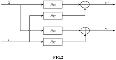
- a filter of a butterfly-shaped structure is to be used to implement polarization demultiplexing.
- the butterfly filter may be implemented by four Finite Impulse Response (FIR) filters.
- the coefficients of the equalizer may include Hxx (f), Hxy (f), Hyy (f), and Hyx (f).
- the jones matrix may be h xx f h xy f h yx f h yy f .
- step 102 a parameter of the jones matrix is acquired using the jones matrix.
- a first parameter, a second parameter, and a third parameter may be acquired by performing a mathematical operation on the jones matrix.
- the first parameter may represent strength of a signal of X-axis polarization.
- the second parameter may represent strength of a signal of Y-axis polarization.
- the third parameter may represent an angle between the signal of X-axis polarization and the signal of Y-axis polarization.
- the third parameter may be expressed by a formula as follows.
- jones _ val
- the n may represent an order of a filter in the equalizer.
- the col may take on a value of 1, 2, ..., or n.
- step 103 when it is determined, using the parameter of the jones matrix, that the coefficients are of singularity characteristics, a coefficient of X-axis or Y-axis polarization among the coefficients is adjusted.
- a signal of X-axis polarization and a signal of Y-axis polarization may converge to each other in terms of polarization.
- the third parameter is less than a first threshold.
- the third parameter is less than the first threshold, it may be determined that the coefficients are of singularity characteristics.
- the first threshold may be set using a result of simulation.
- a first value may be acquired by summing over N acquired instances of the third parameter.
- the N may be an integer greater than 1. It may be determined whether the first value is less than a second threshold. When the first value is less than the second threshold, it may be determined that the coefficients are of singularity characteristics.
- the second threshold may be set using a result of simulation.
- a coefficient of X-axis or Y-axis polarization among the coefficients may be adjusted as follows.
- singularity alteration may be performed on the coefficient of X-axis polarization.
- the coefficient of X-axis polarization having gone through the singularity alteration may be set as the coefficient of Y-axis polarization.
- singularity alteration may be performed on the coefficient of Y-axis polarization.
- the coefficient of Y-axis polarization having gone through the singularity alteration may be set as the coefficient of X-axis polarization.
- Singularity alteration may be performed on the coefficient of X-axis polarization, and the coefficient of X-axis polarization having gone through the singularity alteration may be set as the coefficient of Y-axis polarization as follows.
- Hyy 1, col conj Hxx 1, n + 1 ⁇ col .
- Hyx 1, col ⁇ conj Hxy 1, n + 1 ⁇ col .
- the conj may represent conjugation.
- the n may represent an order of a filter in the equalizer.
- the col may take on a value of 1, 2, ..., or n.
- Singularity alteration may be performed on the coefficient of Y-axis polarization, and the coefficient of Y-axis polarization having gone through the singularity alteration may be set as the coefficient of X-axis polarization as follows.
- Hxx 1, col conj Hyy 1, n + 1 ⁇ col .
- Hxy 1, col ⁇ conj Hyx 1, n + 1 ⁇ col .
- the conj may represent conjugation.
- the n may represent an order of a filter in the equalizer.
- the col may take on a value of 1, 2, ..., or n.
- a pulse signal warning a singularity may be generated.
- the method may further include steps as follows.
- Strength corresponding to a coefficient of X axis or Y-axis polarization of an order of a filter in the equalizer may be determined using two coefficients of X-axis or Y-axis polarization among the coefficients of the equalizer.
- the central position of taps of coefficients of X axis or Y-axis polarization of the equalizer may then be adjusted.
- the central position of taps of coefficients of X axis polarization of the equalizer and the central position of taps of coefficients of Y-axis polarization of the equalizer may be adjusted respectively.
- Strength corresponding to a coefficient of X axis polarization of an order of a filter in the equalizer may be determined using two coefficients of X axis polarization among the coefficients of the equalizer. It may be determined, using the strength corresponding to a coefficient of X axis polarization of an order of the filter, that a central position of taps of coefficients of the equalizer has deviated. The central position of taps of coefficients of the equalizer may then be adjusted.
- Strength corresponding to a coefficient of Y axis polarization of an order of a filter in the equalizer may be determined using two coefficients of Y axis polarization among the coefficients of the equalizer. It may be determined, using the strength corresponding to a coefficient of Y axis polarization of an order of the filter, that a central position of taps of coefficients of the equalizer has deviated. The central position of taps of coefficients of the equalizer may then be adjusted.
- a third parameter may be set as a maximal strength found by searching strength corresponding to a first coefficient of X axis or Y-axis polarization of an order of the filter.
- a fourth parameter may be set as a first position index corresponding to the third parameter.
- a fifth parameter may be set as a maximal strength found by searching strength corresponding to a second coefficient of X axis or Y-axis polarization of an order of the filter.
- a sixth parameter may be set as a second position index corresponding to the fifth parameter.
- the central position of taps of coefficients of X axis or Y-axis polarization of the equalizer may then be moved to the left or to the right by M taps.
- the M may be an integer no less than 1.
- first and second coefficients herein, it indicates but that the coefficients are different coefficients. There is no limitation to a form of a coefficient. Similarly, by first parameter, second parameter,..., it indicates but that the parameters are different parameters. There is no limitation to a form of a parameter.
- a coefficient used in adjusting the central position of taps of coefficients of X axis as well as a parameter and a set threshold thereof may or may not be identical to that used in adjusting the central position of taps of coefficients of Y axis, depending on an actual condition.
- the central position of taps of coefficients of X axis or Y-axis polarization of the equalizer may then be moved to the left or to the right by M taps, as follows.
- both the fourth and sixth parameters are no greater than a third threshold and both the third and fifth parameters are greater than a fifth threshold, the central position of taps of coefficients of X axis or Y-axis polarization of the equalizer may be moved to the right by M taps.
- the central position of taps of coefficients of X axis or Y-axis polarization of the equalizer may be moved to the left by M taps.
- the third threshold, the fourth threshold, the fifth threshold, and the sixth threshold may be set using a result of simulation.
- the central position of taps of coefficients of X axis polarization may be adjusted with formulas as follows.
- the third threshold may be denoted by A1.
- the fourth threshold may be denoted by A2.
- the fifth threshold may be denoted by G1.
- the sixth threshold may be denoted by G2. It may be determined whether the central position has deviated, and the central position may then be adjusted as follows.
- the central position may not be adjusted.
- step 101 to 103 there is no fixed order between adjusting the central position of taps of coefficients of the equalizer and the singularity alteration/adjustment on the coefficients of the equalizer (steps 101 to 103).
- Singularity adjustment may be performed on the coefficients of the equalizer, followed by the process of adjusting the central position of taps of coefficients of the equalizer.
- the flow/process of adjusting the central position of taps of coefficients of the equalizer may be executed after the flow/process of singularity adjustment has completed for some time.
- the flow/process of adjusting the central position of taps of coefficients of the equalizer may be followed by the flow/process of singularity adjustment.
- singularity adjustment may be performed after the flow/process of adjusting the central position of taps of coefficients of the equalizer has completed for some time.
- a jones matrix is acquired with coefficients of an equalizer; a parameter of the jones matrix is acquired using the jones matrix; when it is determined, using the parameter of the jones matrix, that the coefficients are of singularity characteristics, a coefficient of X-axis or Y-axis polarization among the coefficients is adjusted. Only a coefficient of X-axis or Y-axis polarization is adjusted, such that both centers of the coefficients of X-axis and Y-axis polarizations may be adjusted to a central position of taps of coefficients. Thus, the coefficients of the equalizer may be adjusted accurately, thereby improving filter performance and system stability.
- a first value may be acquired by summing over N acquired instances of the third parameter.
- the N may be an integer greater than 1. It may be determined whether the first value is less than a second threshold. When the first value is less than the second threshold, it may be determined that the coefficients are of singularity characteristics. There may be major fluctuation among individual instances of the third parameter. By summing over instances of the third parameter, it may be determined, with increased accuracy, whether the coefficients are of singularity characteristics.
- Strength corresponding to a coefficient of X axis or Y-axis polarization of an order of a filter in the equalizer may be determined using two coefficients of X-axis or Y-axis polarization among the coefficients of the equalizer. It may be determined, using the strength corresponding to a coefficient of X axis or Y-axis polarization of an order of the filter, that a central position of taps of coefficients of X axis or Y-axis polarization of the equalizer has deviated. The central position of taps of coefficients of X axis or Y-axis polarization of the equalizer may then be adjusted. Singularity adjustment and center adjustment on the coefficients of the equalizer may further improve filter performance and system stability.
- a method for adjusting a coefficent of an equalizer includes steps as follows.
- step 301 strength corresponding to a coefficient of X axis or Y-axis polarization of an order of a filter in the equalizer is determined using two coefficients of X-axis or Y-axis polarization among coefficients of the equalizer.
- step 302 when it is determined, using the strength corresponding to a coefficient of X axis or Y-axis polarization of an order of the filter, that a central position of taps of coefficients of X axis or Y-axis polarization of the equalizer has deviated, the central position of taps of coefficients of X axis or Y-axis polarization of the equalizer is adjusted.
- a third parameter may be set as a maximal strength found by searching strength corresponding to a first coefficient of X axis or Y-axis polarization of an order of the filter.
- a fourth parameter may be set as a first position index corresponding to the third parameter.
- a fifth parameter may be set as a maximal strength found by searching strength corresponding to a second coefficient of X axis or Y-axis polarization of an order of the filter.
- a sixth parameter may be set as a second position index corresponding to the fifth parameter.
- the central position of taps of coefficients of X axis or Y-axis polarization of the equalizer may then be moved to the left or to the right by M taps.
- the M may be an integer no less than 1.
- first and second coefficients herein, it indicates but that the coefficients are different coefficients. There is no limitation to a form of a coefficient. Similarly, by first parameter, second parameter,..., it indicates but that the parameters are different parameters. There is no limitation to a form of a parameter.
- a coefficient used in adjusting the central position of taps of coefficients of X axis as well as a parameter and a set threshold thereof may or may not be identical to that used in adjusting the central position of taps of coefficients of Y axis, depending on an actual condition.
- the central position of taps of coefficients of X axis or Y-axis polarization of the equalizer may then be moved to the left or to the right by M taps, as follows.
- both the fourth and sixth parameters are no greater than a third threshold and both the third and fifth parameters are greater than a fifth threshold, the central position of taps of coefficients of X axis or Y-axis polarization of the equalizer may be moved to the right by M taps.
- the central position of taps of coefficients of X axis or Y-axis polarization of the equalizer may be moved to the left by M taps.
- the third threshold, the fourth threshold, the fifth threshold, and the sixth threshold may be set using a result of simulation.
- the central position of taps of coefficients of X axis polarization of the equalizer and the central position of taps of coefficients of Y-axis polarization of the equalizer may be adjusted respectively.
- Strength corresponding to a coefficient of X axis polarization of an order of a filter in the equalizer may be determined using two coefficients of X axis polarization among the coefficients of the equalizer. It may be determined, using the strength corresponding to a coefficient of X axis polarization of an order of the filter, that a central position of taps of coefficients of the equalizer has deviated. The central position of taps of coefficients of the equalizer may then be adjusted.
- Strength corresponding to a coefficient of Y axis polarization of an order of a filter in the equalizer may be determined using two coefficients of Y axis polarization among the coefficients of the equalizer. It may be determined, using the strength corresponding to a coefficient of Y axis polarization of an order of the filter, that a central position of taps of coefficients of the equalizer has deviated. The central position of taps of coefficients of the equalizer may then be adjusted.
- the central position of taps of coefficients of X axis polarization may be adjusted with formulas as follows.
- the third threshold may be denoted by A1.
- the fourth threshold may be denoted by A2.
- the fifth threshold may be denoted by G1.
- the sixth threshold may be denoted by G2. It may be determined whether the central position has deviated, and the central position may then be adjusted as follows.
- the central position may not be adjusted.
- the flow/process of adjusting the central position of taps of coefficients of the equalizer may be performed periodically, without impacting system performance. Power consumption by equipment may be reduced as well.
- strength corresponding to a coefficient of X axis or Y-axis polarization of an order of a filter in the equalizer is determined using two coefficients of X-axis or Y-axis polarization among coefficients of the equalizer; and when it is determined, using the strength corresponding to a coefficient of X axis or Y-axis polarization of an order of the filter, that a central position of taps of coefficients of X axis or Y-axis polarization of the equalizer has deviated, the central position of taps of coefficients of X axis or Y-axis polarization of the equalizer is adjusted.
- the process of adjusting coefficients of an equalizer may be explained with a 100G DSP chip in a communication system in 100G optical transmission in a bearer network as an example.
- a DSP chip and a multiplexer (MUX) chip in a 100G optical module are key to 100G long-distance transmission. Limited by a technical threshold and a high capital input, not many manufacturers are cable of developing a DSP chip. One may have to develop a DSP chip by oneself. A competitor who has developed a DSP chip successfully may put major stress on products of a 100G system by other manufacturers in terms of cost. The solution used by the competitor to develop the DSP chip may take away a substantial market share from an independent design company. Impact on market expectation may immediately lead to increasingly cautious investment on a DSP chip project by other manufacturers.
- a 100G DSP chip may apply in a 100G optical module in a 100G line card, mainly for processing a data signal, forming a vital part of the 100G optical module.
- Adaptive equalization may include Polarization Mode Dispersion (PMD), Chromatic Dispersion (CD), polarization mode demultiplexing, etc.
- PMD Polarization Mode Dispersion
- CD Chromatic Dispersion
- Adaptive equalization may be a vital link in processing a data signal by a 100G DSP chip.
- adaptive equalization may be implemented using blind equalization by a Constant Modulus Algorithm (CMA).
- CMA Constant Modulus Algorithm
- the blind equalization by the CMA makes up for damage to a signal caused by an imperfect channel.
- Interaction between light components of different polarizations may be compensated using a filter of a butterfly-shaped structure.
- a filter of a butterfly-shaped structure may consist of four FIR filters.
- X and Y may be two polarized signals, respectively.
- Modulation by polarization multiplexing may be used in a communication system. A polarized signal may deviate during transmission, causing interference to another polarized signal.
- a filter of a butterfly-shaped structure is to be used to implement polarization demultiplexing.
- the H (n-1) may be a coefficient for a last beat.
- the X out may be output filtered data.
- the X* in may be an input vector of a filter involved in computing the X out .
- the k may depend on a hardware delay.
- the R may be a configurable CMA output power factor.
- the ⁇ may be a factor for stepwise time variation.
- Adjustment of a coefficent of an equalizer may include singularity adjustment and center adjustment.
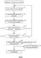
- singularity adjustment singularity in coefficents of an equalizer may be detected using a jones matrix of the coefficents of the equalizer. As shown in FIG.5 , singularity adjustment may include steps as follows.
- a jones matrix may be computed with coefficients of an equalizer.
- the jones matrix may be h xx f h xy f h yx f h yy f .
- step 502 three parameters of the jones matrix may be computed.
- jones _ x
- 2 jones _ y
- the n may represent an order of a filter in the equalizer.
- the col may take on a value of 1, 2, ..., or n.
- the parameters of the jones matrix may be referred to as real-time parameters.
- step 503 it may be determined whether jones_val is less than a first threshold. When jones_val is less than the first threshold, step 504 may be executed. Otherwise, step 501 may be executed.
- the first threshold may be set using a result of simulation.
- jones_val When jones_val is greater than the first threshold, it means that the coefficients of the equalizer show no singularity characteristics and do not need to be adjusted. In this case, no signal warning a singularity may be generated.
- step 504 a signal warning a singularity may be generated, and then steps 505 and 506 may be executed.
- the generated signal warning a singularity may be a pulse signal.
- step 505 singularity adjustment may be performed on the coefficients of the equalizer.
- jones_x may be compared to jones_y. Singularity alteration may be performed on the coefficient of a polarization with a larger jones value. The coefficient having gone through the singularity alteration may then be set as the coefficient of a polarization with a smaller jones value. For example, when jones_x is less/smaller than jones_y, singularity alteration may have to be performed on the coefficient of X-axis polarization.
- the coefficient of Y-axis polarization having gone through the singularity alteration may have to be set as the coefficient of X-axis polarization.
- singularity alteration may have to be performed on the coefficient of Y-axis polarization. That is, the coefficient of X-axis polarization having gone through the singularity alteration may have to be set as the coefficient of Y-axis polarization.
- Singularity adjustment may be performed on the coefficient of X-axis polarization as follows.
- Hxx 1, col conj Hyy 1, n + 1 ⁇ col .
- Hxy 1, col ⁇ conj Hyx 1, n + 1 ⁇ col .
- Singularity adjustment may be performed on the coefficient of Y-axis polarization as follows.
- Hyy 1, col conj Hxx 1, n + 1 ⁇ col .
- Hyx 1, col ⁇ conj Hxy 1, n + 1 ⁇ col .
- the conj may represent conjugation.
- the n may represent an order of a filter in the equalizer.
- the col may take on a value of 1, 2, ..., or n.
- step 506 a timer 2 for masking the warning may be started.
- the timer 2 for masking the warning may serve to generate a signal to mask the warning to allow periodical singularity adjustment on the coefficients of the equalizer.
- singularity adjustment may include steps as follows.
- a jones matrix may be computed with coefficients of an equalizer.
- the jones matrix may be h xx f h xy f h yx f h yy f .
- step 602 three parameters of the jones matrix may be computed.
- jones _ x
- 2 jones _ y
- 2 jones _ val
- the n may represent an order of a filter in the equalizer.
- the col may take on a value of 1, 2, ..., or n.
- the parameters of the jones matrix may be referred to as real-time parameters.
- step 603 a sum over jones_val in time may be computed.
- the N may be 32.
- step 604 it may be determined whether a count by a timer 1 starting from 1 has reached 31. When it has, step 605 may be executed. Otherwise, step 601 may be executed.
- step 605 it may be determined whether the sum over jones_val in time is less than a second threshold. When it is, step 606 may be executed. Otherwise, step 601 may be executed.
- the second threshold may be set using a result of simulation.
- step 606 a signal warning a singularity may be generated. Then steps 607 and 608 may be executed.
- the generated signal warning a singularity may be a pulse signal.
- step 607 singularity adjustment may be performed on the coefficients of the equalizer.
- jones_x may be compared to jones_y. Singularity alteration may be performed on the coefficient of a polarization with a larger jones value. The coefficient having gone through the singularity alteration may then be set as the coefficient of a polarization with a smaller jones value. For example, when jones_x is less/smaller than jones_y, singularity alteration may have to be performed on the coefficient of X-axis polarization.
- the coefficient of Y-axis polarization having gone through the singularity alteration may have to be set as the coefficient of X-axis polarization.
- singularity alteration may have to be performed on the coefficient of Y-axis polarization. That is, the coefficient of X-axis polarization having gone through the singularity alteration may have to be set as the coefficient of Y-axis polarization.
- Singularity adjustment may be performed on the coefficient of X-axis polarization as follows.
- Hxx 1, col conj Hyy 1, n + 1 ⁇ col .
- Hxy 1, col ⁇ conj Hyx 1, n + 1 ⁇ col .
- Singularity adjustment may be performed on the coefficient of Y-axis polarization as follows.
- Hyy 1, col conj Hxx 1, n + 1 ⁇ col .
- Hyx 1, col ⁇ conj Hxy 1, n + 1 ⁇ col .
- the conj may represent conjugation.
- the n may represent an order of a filter in the equalizer.
- the col may take on a value of 1, 2, ..., or n.
- step 608 a timer 2 for masking the warning may be started.
- the timer 2 for masking the warning may serve to generate a signal to mask the warning to allow periodical singularity adjustment on the coefficients of the equalizer.
- center adjustment on coefficients of an equalizer may include steps as follow.
- a third parameter, a fourth parameter, a fifth parameter, and a sixth parameter may be computed.
- the m1 may be a maximal value among h1(1, col).
- the w1 may be a position index corresponding to the maximal value among h1(1, col).
- the m2 may be a maximal value among h2(1, col).
- the w2 may be a position index corresponding to the maximal value among h2(1, col).
- steps 702 to 708 may be executed.
- step 704 the central position may be moved to the right by one tap, and then step 708 may be executed.
- step 706 the central position may be moved to the left by one tap, and then step 708 may be executed.
- step 708 may be executed, skipping adjustment to the central position.
- step 708 the flow may end.
- both singularity adjustment and center adjustment may be performed periodically. No adjustment may be performed at any other time. As change in a channel is in general slow, periodical adjustment will have no impact on system performance. Neither center adjustment nor further singularity adjustment may be conducted within a period of time after singularity adjustment has been done. In an actual application, timing and mask of singularity adjustment and center adjustment may be selected with reference to FIG.8 . By monitoring, and performing singularity adjustment and center adjustment on, coefficients of an equalizer, filter performance and system stability may be improved.
- coefficients of an equalizer may be updated adaptively with a dynamic step size.
- the coefficients of the equalizer may be monitored in real time. When singularity characteristics of the coefficients are found, singularity adjustment may be performed. When a center of the coefficients is at a boundary of taps, center adjustment may be performed.
- a central position of coefficents of an equalizer is adjustable, of good real-time performance, and converges fast. Hardware implementation thereof is simple. Thus, performance of a 100G DSP chip in terms of equalization is improved, thereby improving overall performance of a 100G DSP processing chip, reducing an overall cost.
- blind equalization by the CMA may include filter, coefficient adjustment, and center adjustment.
- Input data may be filtered using adjusted and updated coefficients.
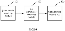
- a device for adjusting a coefficent of an equalizer includes a jones matrix acquiring module 101, a first parameter acquiring module 102, and a first adjusting module 103.
- the jones matrix acquiring module 101 is arranged for: acquiring a jones matrix with coefficients of an equalizer.
- the first parameter acquiring module 102 is arranged for: acquiring a parameter of the jones matrix.
- the first adjusting module 103 is arranged for: in response to determining, using the parameter of the jones matrix, that the coefficients are of singularity characteristics, adjusting a coefficient of X-axis or Y-axis polarization among the coefficients.
- X and Y may be two polarized signals, respectively.
- Modulation by polarization multiplexing may be used in a communication system.
- a polarized signal may deviate during transmission, causing interference to another polarized signal.
- a filter of a butterfly-shaped structure is to be used to implement polarization demultiplexing.
- the butterfly filter may be implemented by four Finite Impulse Response (FIR) filters.
- the coefficients of the equalizer may include Hxx (f), Hxy (f), Hyy (f), and Hyx (f).
- the jones matrix may be h xx f h xy f h yx f h yy f .
- the first parameter acquiring module 102 may be arranged for: acquiring, by performing a mathematical operation on the jones matrix, a first parameter, a second parameter, and a third parameter.
- the first parameter may represent strength of a signal of X-axis polarization.
- the second parameter may represent strength of a signal of Y-axis polarization.
- the third parameter may represent an angle between the signal of X-axis polarization and the signal of Y-axis polarization.
- the third parameter may be expressed by a formula as follows.
- jones _ val
- the n may represent an order of a filter in the equalizer.
- the col may take on a value of 1, 2, ..., or n.
- a signal of X-axis polarization and a signal of Y-axis polarization may converge to each other in terms of polarization.
- the first adjusting module 103 may be arranged for determining whether the third parameter is less than a first threshold; in response to determining that the third parameter is less than the first threshold, determining that the coefficients are of singularity characteristics.
- the first threshold may be set using a result of simulation.
- the first adjusting module 103 may be arranged for: acquiring a first value by summing over N instances of the third parameter, the N being an integer greater than 1; determining whether the first value is less than a second threshold; in response to determining that the first value is less than the second threshold, determining that the coefficients are of singularity characteristics.
- the second threshold may be set using a result of simulation.
- a coefficient of X-axis or Y-axis polarization among the coefficients may be adjusted as follows.
- the first adjusting module 103 may be arranged for: in response to determining that the first parameter is greater than the second parameter, performing singularity alteration on the coefficient of X-axis polarization; setting the coefficient of X-axis polarization having gone through the singularity alteration as the coefficient of Y-axis polarization.
- the first adjusting module 103 may be arranged for: in response to determining that the first parameter is less than the second parameter, performing singularity alteration on the coefficient of Y-axis polarization; setting the coefficient of Y-axis polarization having gone through the singularity alteration as the coefficient of X-axis polarization.
- Singularity alteration may be performed on the coefficient of X-axis polarization, and the coefficient of X-axis polarization having gone through the singularity alteration may be set as the coefficient of Y-axis polarization as follows.
- Hyy 1, col conj Hxx 1, n + 1 ⁇ col .
- Hyx 1, col ⁇ conj Hxy 1, n + 1 ⁇ col .
- the conj may represent conjugation.
- the n may represent an order of a filter in the equalizer.
- the col may take on a value of 1, 2, ..., or n.
- Singularity alteration may be performed on the coefficient of Y-axis polarization, and the coefficient of Y-axis polarization having gone through the singularity alteration may be set as the coefficient of X-axis polarization as follows.
- Hxx 1, col conj Hyy 1, n + 1 ⁇ col .
- Hxy 1, col ⁇ conj Hyx 1, n + 1 ⁇ col .
- the conj may represent conjugation.
- the n may represent an order of a filter in the equalizer.
- the col may take on a value of 1, 2, ..., or n.
- the device may further include a first warning module.
- the first warning module may be arranged for: in response to determining that the coefficients are of singularity characteristics, before the coefficient of X-axis or Y-axis polarization among the coefficients is adjusted, generating a warning of singularity.
- the first warning module may generate a pulse signal warning a singularity.
- the device may further include a first strength determining module and a second adjusting module.
- the first strength determining module may be arranged for: determining, using two coefficients of X-axis or Y-axis polarization among the coefficients of the equalizer, strength corresponding to a coefficient of X axis or Y-axis polarization of an order of a filter in the equalizer.
- the second adjusting module may be arranged for: in response to determining, using the strength corresponding to a coefficient of X axis or Y-axis polarization of an order of the filter, that a central position of taps of coefficients of X axis or Y-axis polarization of the equalizer has deviated, adjusting the central position of taps of coefficients of X axis or Y-axis polarization of the equalizer.
- the central position of taps of coefficients of X axis polarization of the equalizer and the central position of taps of coefficients of Y-axis polarization of the equalizer may be adjusted respectively.
- the first strength determining module may be arranged for: determining, using two coefficients of X axis polarization among the coefficients of the equalizer, strength corresponding to a coefficient of X axis polarization of an order of a filter in the equalizer.
- the second adjusting module may be arranged for: in response to determining, using the strength corresponding to a coefficient of X axis polarization of an order of the filter, that a central position of taps of coefficients of the equalizer has deviated, adjusting the central position of taps of coefficients of the equalizer.
- the first strength determining module may be arranged for: determining, using two coefficients of Y axis polarization among the coefficients of the equalizer, strength corresponding to a coefficient of Y axis polarization of an order of a filter in the equalizer.
- the second adjusting module may be arranged for: in response to determining, using the strength corresponding to a coefficient of Y axis polarization of an order of the filter, that a central position of taps of coefficients of the equalizer has deviated, adjusting the central position of taps of coefficients of the equalizer.
- the second adjusting module may be arranged for: setting a third parameter as a maximal strength found by searching strength corresponding to a first coefficient of X axis or Y-axis polarization of an order of the filter, and setting a fourth parameter as a first position index corresponding to the third parameter.
- the second adjusting module may be arranged for: setting a fifth parameter as a maximal strength found by searching strength corresponding to a second coefficient of X axis or Y-axis polarization of an order of the filter, and setting a sixth parameter as a second position index corresponding to the fifth parameter.
- the second adjusting module may be arranged for: in response to determining, using the third parameter, the fourth parameter, the fifth parameter, the sixth parameter, and a preset condition, that the central position of taps of coefficients of X axis or Y-axis polarization of the equalizer has deviated, moving the central position of taps of coefficients of X axis or Y-axis polarization of the equalizer to the left or to the right by M taps.
- the M may be an integer no less than 1.
- first and second coefficients herein, it indicates but that the coefficients are different coefficients. There is no limitation to a form of a coefficient. Similarly, by first parameter, second parameter,..., it indicates but that the parameters are different parameters. There is no limitation to a form of a parameter.
- a coefficient used in adjusting the central position of taps of coefficients of X axis as well as a parameter and a set threshold thereof may or may not be identical to that used in adjusting the central position of taps of coefficients of Y axis, depending on an actual condition.
- the central position of taps of coefficients of X axis or Y-axis polarization of the equalizer may then be moved to the left or to the right by M taps, as follows.
- the second adjusting module may be arranged for: in response to determining that both the fourth and sixth parameters are no greater than a third threshold and both the third and fifth parameters are greater than a fifth threshold, moving the central position of taps of coefficients of X axis or Y-axis polarization of the equalizer to the right by M taps.
- the second adjusting module may be arranged for: in response to determining that both the fourth and sixth parameters are no less than a fourth threshold and both the third and fifth parameters are greater than the fifth threshold, moving the central position of taps of coefficients of X axis or Y-axis polarization of the equalizer to the left by M taps.
- the third threshold, the fourth threshold, the fifth threshold, and the sixth threshold may be set using a result of simulation.
- the central position of taps of coefficients of X axis polarization may be adjusted with formulas as follows.
- the third threshold may be denoted by A1.
- the fourth threshold may be denoted by A2.
- the fifth threshold may be denoted by G1.
- the sixth threshold may be denoted by G2. It may be determined whether the central position has deviated, and the central position may then be adjusted as follows.
- the central position may not be adjusted by the second adjusting module.
- Singularity adjustment may be performed on the coefficients of the equalizer, followed by the process of adjusting the central position of taps of coefficients of the equalizer.
- the flow/process of adjusting the central position of taps of coefficients of the equalizer may be executed after the flow/process of singularity adjustment has completed for some time.
- the flow/process of adjusting the central position of taps of coefficients of the equalizer may be followed by the flow/process of singularity adjustment.
- singularity adjustment may be performed after the flow/process of adjusting the central position of taps of coefficients of the equalizer has completed for some time.
- the jones matrix acquiring module 101, the first parameter acquiring module 102, the first adjusting module 103, the first strength determining module, and the second adjusting module may be implemented by a Central Processing Unit (CPU), a Micro Control Unit (MCU), a DSP, or a Field - Programmable Gate Array (FPGA) in the device for adjusting a coefficent of an equalizer.
- the first warning module may be implemented by an alarm in the device for adjusting a coefficent of an equalizer.
- a jones matrix acquiring module 101 acquires a jones matrix with coefficients of an equalizer; a first parameter acquiring module 102 acquires a parameter of the jones matrix using the jones matrix; a first adjusting module 103 determines, using the parameter of the jones matrix, that the coefficients are of singularity characteristics, and then adjusts a coefficient of X-axis or Y-axis polarization among the coefficients.
- the first adjusting module 103 may be arranged for: acquiring a first value by summing over N instances of the third parameter, the N being an integer greater than 1; determining whether the first value is less than a second threshold; in response to determining that the first value is less than the second threshold, determining that the coefficients are of singularity characteristics. There may be major fluctuation among individual instances of the third parameter. By summing over instances of the third parameter, it may be determined, with increased accuracy, whether the coefficients are of singularity characteristics.
- the first strength determining module may be arranged for: determining, using two coefficients of X-axis or Y-axis polarization among the coefficients of the equalizer, strength corresponding to a coefficient of X axis or Y-axis polarization of an order of a filter in the equalizer.
- the second adjusting module may be arranged for: in response to determining, using the strength corresponding to a coefficient of X axis or Y-axis polarization of an order of the filter, that a central position of taps of coefficients of X axis or Y-axis polarization of the equalizer has deviated, adjusting the central position of taps of coefficients of X axis or Y-axis polarization of the equalizer. Singularity adjustment and center adjustment on the coefficients of the equalizer may further improve filter performance and system stability.
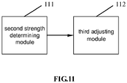
- a device for adjusting a coefficent of an equalizer includes a second strength determining module 111 and a third adjusting module 112.
- the second strength determining module 111 is arranged for: determining, using two coefficients of X-axis or Y-axis polarization among coefficients of the equalizer, strength corresponding to a coefficient of X axis or Y-axis polarization of an order of a filter in the equalizer.
- the third adjusting module 112 is arranged for: in response to determining, using the strength corresponding to a coefficient of X axis or Y-axis polarization of an order of the filter, that a central position of taps of coefficients of X axis or Y-axis polarization of the equalizer has deviated, adjusting the central position of taps of coefficients of X axis or Y-axis polarization of the equalizer.
- the third adjusting module 112 may further include a second parameter acquiring module, a third parameter acquiring module, and a center adjusting module.
- the second parameter acquiring module may be arranged for: setting a third parameter as a maximal strength found by searching strength corresponding to a first coefficient of X axis or Y-axis polarization of an order of the filter, and setting a fourth parameter as a first position index corresponding to the third parameter.
- the third parameter acquiring module may be arranged for: setting a fifth parameter as a maximal strength found by searching strength corresponding to a second coefficient of X axis or Y-axis polarization of an order of the filter, and setting a sixth parameter as a second position index corresponding to the fifth parameter.
- the center adjusting module may be arranged for: in response to determining, using the third parameter, the fourth parameter, the fifth parameter, the sixth parameter, and a preset condition, that the central position of taps of coefficients of X axis or Y-axis polarization of the equalizer has deviated, moving the central position of taps of coefficients of X axis or Y-axis polarization of the equalizer to the left or to the right by M taps.
- the M may be an integer no less than 1.
- first and second coefficients herein, it indicates but that the coefficients are different coefficients. There is no limitation to a form of a coefficient. Similarly, by first parameter, second parameter,..., it indicates but that the parameters are different parameters. There is no limitation to a form of a parameter.
- a coefficient used in adjusting the central position of taps of coefficients of X axis as well as a parameter and a set threshold thereof may or may not be identical to that used in adjusting the central position of taps of coefficients of Y axis, depending on an actual condition.
- the center adjusting module may be arranged for:
- the third threshold, the fourth threshold, the fifth threshold, and the sixth threshold may be set using a result of simulation.
- the central position of taps of coefficients of X axis polarization of the equalizer and the central position of taps of coefficients of Y-axis polarization of the equalizer may be adjusted respectively.
- the second strength determining module 111 may be arranged for: determining, using two coefficients of X axis polarization among the coefficients of the equalizer, strength corresponding to a coefficient of X axis polarization of an order of a filter in the equalizer.
- the third adjusting module 112 may be arranged for: in response to determining, using the strength corresponding to a coefficient of X axis polarization of an order of the filter, that a central position of taps of coefficients of the equalizer has deviated, adjusting the central position of taps of coefficients of the equalizer.
- the second strength determining module 111 may be arranged for: determining, using two coefficients of Y axis polarization among the coefficients of the equalizer, strength corresponding to a coefficient of Y axis polarization of an order of a filter in the equalizer.
- the third adjusting module 112 may be arranged for: in response to determining, using the strength corresponding to a coefficient of Y axis polarization of an order of the filter, that a central position of taps of coefficients of the equalizer has deviated, adjusting the central position of taps of coefficients of the equalizer.
- the central position of taps of coefficients of X axis polarization may be adjusted with formulas as follows.
- the third threshold may be denoted by A1.
- the fourth threshold may be denoted by A2.
- the fifth threshold may be denoted by G1.
- the sixth threshold may be denoted by G2. It may be determined whether the central position has deviated, and the central position may then be adjusted as follows.
- the central position may not be adjusted.
- the flow/process of adjusting the central position of taps of coefficients of the equalizer may be performed periodically, without impacting system performance. Power consumption by equipment may be reduced as well.
- the second strength determining module 111, the third adjusting module 112, the second parameter acquiring module, the third parameter acquiring module, and the center adjusting module may be implemented by a CPU, an MCU, a DSP, or an FPGA in the device for adjusting a coefficent of an equalizer.
- the second warning module may be implemented by an alarm in the device for adjusting a coefficent of an equalizer.
- the second strength determining module 111 determines, using two coefficients of X-axis or Y-axis polarization among coefficients of the equalizer, strength corresponding to a coefficient of X axis or Y-axis polarization of an order of a filter in the equalizer.
- the third adjusting module 112 determines, using the strength corresponding to a coefficient of X axis or Y-axis polarization of an order of the filter, that a central position of taps of coefficients of X axis or Y-axis polarization of the equalizer has deviated, and then adjusts the central position of taps of coefficients of X axis or Y-axis polarization of the equalizer.
- the coefficients of the equalizer may be adjusted accurately, thereby improving filter performance and system stability.
- an embodiment herein may provide a method, system, or computer program product. Therefore, an embodiment herein may take on a form of hardware, software, or a combination thereof. In addition, an embodiment herein may take on a form of a computer program product implemented on one or more computer available storage media (including but not limited to, magnetic disk memory, optic memory, and the like) containing computer available program codes.
- a computer available storage media including but not limited to, magnetic disk memory, optic memory, and the like
- each flow in the flowcharts and/or each block in the block diagrams as well as combination of flows in the flowcharts and/or blocks in the block diagrams may be implemented by instructions of a computer program.
- Such instructions may be offered in a processor of a general-purpose computer, a dedicated computer, an embedded processor or other programmable data processing devices to generate a machine, such that a device with a function specified in one or more flows of the flowcharts and/or one or more blocks in the block diagrams is produced by instructions executed by a processor of a computer or other programmable data processing devices.
- These computer-program instructions may also be stored in a non-transitory computer-readable memory capable of guiding a computer or another programmable data processing device to work in a given way, such that the instructions stored in the computer-readable memory generate a manufactured good including an instruction device for implementing a function specified in one or more flows of the flowcharts and/or one or more blocks in the block diagrams.
- These computer-program instructions may also be loaded in a computer or other programmable data processing devices, which thus executes a series of operations thereon to generate computer-implemented processing, such that the instructions executed on the computer or other programmable data processing devices provide the steps for implementing the function specified in one or more flows of the flowcharts or one or more blocks in the block diagrams.
- a transitory or non-transitory computer-readable storage medium has stored therein instructions that, when executed by at least one processor, causes the at least one processor to perform the method for adjusting a coefficent of an equalizer according to embodiments herein.
Landscapes
- Engineering & Computer Science (AREA)
- Computer Networks & Wireless Communication (AREA)
- Signal Processing (AREA)
- Power Engineering (AREA)
- Physics & Mathematics (AREA)
- Electromagnetism (AREA)
- Mathematical Physics (AREA)
- Optical Communication System (AREA)
- Filters That Use Time-Delay Elements (AREA)
Abstract
Description
- The present disclosure relates to communication via optical transmission, and in particular to a method and device for adjusting a coefficent of an equalizer, and a computer-readable storage medium.
- No ideal transmission characteristics may be achieved in an actual communication system due to a change in channel characteristics and an error in filter design. There may be inter-symbol crosstalk at a sampling point, leading to degraded system performance. To reduce impact of inter-symbol crosstalk, system characteristics are to be corrected or compensated, generally by including, in a communication system, a tunable filter. Such a compensating filter may be referred to as an equalizer. An equalizer in a communication system is a device for correcting amplitude-frequency characteristics and phase-frequency characteristics of a transmission channel.
- Little or no control over a coefficent of an equalizer is involved in existing equalization for a high-speed optical transmission system. A coefficent of an equalizer is a crucial factor in system stability.
- With an existing solution for adjusting a coefficent of an equalizer, both coefficients of X-axis and Y-axis polarizations may be shifted in a same direction, such that a center of the coefficients of X-axis and Y-axis polarizations may not be adjusted to a central position of taps of coefficients, impacting system stability.
- Embodiments herein provide a method and device for adjusting a coefficent of an equalizer, and a computer-readable storage medium.
- According to an embodiment herein, a method for adjusting a coefficent of an equalizer includes:
- acquiring a jones matrix with coefficients of an equalizer;
- acquiring a parameter of the jones matrix; and
- in response to determining, using the parameter of the jones matrix, that the coefficients are of singularity characteristics, adjusting a coefficient of X-axis or Y-axis polarization among the coefficients.
- The acquiring a parameter of the jones matrix may include:
- acquiring, by performing a mathematical operation on the jones matrix, a first parameter, a second parameter, and a third parameter. The first parameter may represent strength of a signal of X-axis polarization. The second parameter may represent strength of a signal of Y-axis polarization. The third parameter may represent an angle between the signal of X-axis polarization and the signal of Y-axis polarization.
- The determining, using the parameter of the jones matrix, that the coefficients are of singularity characteristics may include:
- determining whether the third parameter is less than a first threshold; in response to determining that the third parameter is less than the first threshold, determining that the coefficients are of singularity characteristics;
- alternatively,
- acquiring a first value by summing over N instances of the third parameter, the N being an integer greater than 1; determining whether the first value is less than a second threshold; in response to determining that the first value is less than the second threshold, determining that the coefficients are of singularity characteristics.
- The method may further include: in response to determining that the coefficients are of singularity characteristics, before the adjusting a coefficient of X-axis or Y-axis polarization among the coefficients,
generating a warning of singularity. - The adjusting a coefficient of X-axis or Y-axis polarization among the coefficients may include:
- in response to determining that the first parameter is greater than the second parameter, performing singularity alteration on the coefficient of X-axis polarization, and setting the coefficient of X-axis polarization having gone through the singularity alteration as the coefficient of Y-axis polarization; alternatively,
- in response to determining that the first parameter is less than the second parameter, performing singularity alteration on the coefficient of Y-axis polarization, and setting the coefficient of Y-axis polarization having gone through the singularity alteration as the coefficient of X-axis polarization.
- The performing singularity alteration on the coefficient of X-axis polarization, and setting the coefficient of X-axis polarization having gone through the singularity alteration as the coefficient of Y-axis polarization may include:


- The conj may represent conjugation. The n may represent an order of a filter in the equalizer. The col may take on a value of 1, 2, ..., or n.
- The performing singularity alteration on the coefficient of Y-axis polarization, and setting the coefficient of Y-axis polarization having gone through the singularity alteration as the coefficient of X-axis polarization may include:


- The conj may represent conjugation. The n may represent an order of a filter in the equalizer. The col may take on a value of 1, 2, ..., or n.
- The method may further include:
- determining, using two coefficients of X-axis or Y-axis polarization among the coefficients of the equalizer, strength corresponding to a coefficient of X axis or Y-axis polarization of an order of a filter in the equalizer; and
- in response to determining, using the strength corresponding to a coefficient of X axis or Y-axis polarization of an order of the filter, that a central position of taps of coefficients of X axis or Y-axis polarization of the equalizer has deviated, adjusting the central position of taps of coefficients of X axis or Y-axis polarization of the equalizer.
- The in response to determining, using the strength corresponding to a coefficient of X axis or Y-axis polarization of an order of the filter, that a central position of taps of coefficients of X axis or Y-axis polarization of the equalizer has deviated, adjusting the central position of taps of coefficients of X axis or Y-axis polarization of the equalizer may include:
- setting a third parameter as a maximal strength found by searching strength corresponding to a first coefficient of X axis or Y-axis polarization of an order of the filter, and setting a fourth parameter as a first position index corresponding to the third parameter;
- setting a fifth parameter as a maximal strength found by searching strength corresponding to a second coefficient of X axis or Y-axis polarization of an order of the filter, and setting a sixth parameter as a second position index corresponding to the fifth parameter; and
- in response to determining, using the third parameter, the fourth parameter, the fifth parameter, the sixth parameter, and a preset condition, that the central position of taps of coefficients of X axis or Y-axis polarization of the equalizer has deviated, moving the central position of taps of coefficients of X axis or Y-axis polarization of the equalizer to the left or to the right by M taps, the M being an integer no less than 1.
- The in response to determining, using the third parameter, the fourth parameter, the fifth parameter, the sixth parameter, and a preset condition, that the central position of taps of coefficients of X axis or Y-axis polarization of the equalizer has deviated, moving the central position of taps of coefficients of X axis or Y-axis polarization of the equalizer to the left or to the right by M taps may include:
- in response to determining that both the fourth and sixth parameters are no greater than a third threshold and both the third and fifth parameters are greater than a fifth threshold, moving the central position of taps of coefficients of X axis or Y-axis polarization of the equalizer to the right by M taps; alternatively,
- in response to determining that both the fourth and sixth parameters are no less than a fourth threshold and both the third and fifth parameters are greater than the fifth threshold, moving the central position of taps of coefficients of X axis or Y-axis polarization of the equalizer to the left by M taps.
- According to an embodiment herein, a method for adjusting a coefficent of an equalizer includes:
- determining, using two coefficients of X-axis or Y-axis polarization among coefficients of the equalizer, strength corresponding to a coefficient of X axis or Y-axis polarization of an order of a filter in the equalizer; and
- in response to determining, using the strength corresponding to a coefficient of X axis or Y-axis polarization of an order of the filter, that a central position of taps of coefficients of X axis or Y-axis polarization of the equalizer has deviated, adjusting the central position of taps of coefficients of X axis or Y-axis polarization of the equalizer.
- The in response to determining, using the strength corresponding to a coefficient of X axis or Y-axis polarization of an order of the filter, that a central position of taps of coefficients of X axis or Y-axis polarization of the equalizer has deviated, adjusting the central position of taps of coefficients of X axis or Y-axis polarization of the equalizer may include:
- setting a third parameter as a maximal strength found by searching strength corresponding to a first coefficient of X axis or Y-axis polarization of an order of the filter, and setting a fourth parameter as a first position index corresponding to the third parameter;
- setting a fifth parameter as a maximal strength found by searching strength corresponding to a second coefficient of X axis or Y-axis polarization of an order of the filter, and setting a sixth parameter as a second position index corresponding to the fifth parameter; and
- in response to determining, using the third parameter, the fourth parameter, the fifth parameter, the sixth parameter, and a preset condition, that the central position of taps of coefficients of X axis or Y-axis polarization of the equalizer has deviated, moving the central position of taps of coefficients of X axis or Y-axis polarization of the equalizer to the left or to the right by M taps, the M being an integer no less than 1.
- The in response to determining, using the third parameter, the fourth parameter, the fifth parameter, the sixth parameter, and a preset condition, that the central position of taps of coefficients of X axis or Y-axis polarization of the equalizer has deviated, moving the central position of taps of coefficients of X axis or Y-axis polarization of the equalizer to the left or to the right by M taps may include:
- in response to determining that both the fourth and sixth parameters are no greater than a third threshold and both the third and fifth parameters are greater than a fifth threshold, moving the central position of taps of coefficients of X axis or Y-axis polarization of the equalizer to the right by M taps; alternatively,
- in response to determining that both the fourth and sixth parameters are no less than a fourth threshold and both the third and fifth parameters are greater than the fifth threshold, moving the central position of taps of coefficients of X axis or Y-axis polarization of the equalizer to the left by M taps.
- According to an embodiment herein, a device for adjusting a coefficent of an equalizer includes a first jones matrix acquiring module, a first parameter acquiring module, and a first adjusting module.
- The first jones matrix acquiring module is arranged for: acquiring a jones matrix with coefficients of an equalizer.
- The first parameter acquiring module is arranged for: acquiring a parameter of the jones matrix.
- The first adjusting module is arranged for: in response to determining, using the parameter of the jones matrix, that the coefficients are of singularity characteristics, adjusting a coefficient of X-axis or Y-axis polarization among the coefficients.
- The device may further include a first warning module arranged for: in response to determining that the coefficients are of singularity characteristics, before the coefficient of X-axis or Y-axis polarization among the coefficients is adjusted, generating a warning of singularity.
- The device may further include a first strength determining module and a second adjusting module.
- The first strength determining module may be arranged for: determining, using two coefficients of X-axis or Y-axis polarization among the coefficients of the equalizer, strength corresponding to a coefficient of X axis or Y-axis polarization of an order of a filter in the equalizer.
- The second adjusting module may be arranged for: in response to determining, using the strength corresponding to a coefficient of X axis or Y-axis polarization of an order of the filter, that a central position of taps of coefficients of X axis or Y-axis polarization of the equalizer has deviated, adjusting the central position of taps of coefficients of X axis or Y-axis polarization of the equalizer.
- According to an embodiment herein, a device for adjusting a coefficent of an equalizer includes a second strength determining module and a third adjusting module.
- The second strength determining module is arranged for: determining, using two coefficients of X-axis or Y-axis polarization among coefficients of the equalizer, strength corresponding to a coefficient of X axis or Y-axis polarization of an order of a filter in the equalizer.
- The third adjusting module is arranged for: in response to determining, using the strength corresponding to a coefficient of X axis or Y-axis polarization of an order of the filter, that a central position of taps of coefficients of X axis or Y-axis polarization of the equalizer has deviated, adjusting the central position of taps of coefficients of X axis or Y-axis polarization of the equalizer.
- The third adjusting module may further include a second parameter acquiring module, a third parameter acquiring module, and a center adjusting module.
- The second parameter acquiring module may be arranged for: setting a third parameter as a maximal strength found by searching strength corresponding to a first coefficient of X axis or Y-axis polarization of an order of the filter, and setting a fourth parameter as a first position index corresponding to the third parameter.
- The third parameter acquiring module may be arranged for: setting a fifth parameter as a maximal strength found by searching strength corresponding to a second coefficient of X axis or Y-axis polarization of an order of the filter, and setting a sixth parameter as a second position index corresponding to the fifth parameter.
- The center adjusting module may be arranged for: in response to determining, using the third parameter, the fourth parameter, the fifth parameter, the sixth parameter, and a preset condition, that the central position of taps of coefficients of X axis or Y-axis polarization of the equalizer has deviated, moving the central position of taps of coefficients of X axis or Y-axis polarization of the equalizer to the left or to the right by M taps, the M being an integer no less than 1.
- According to an embodiment herein, a computer-readable storage medium stores therein instructions which when being executed, cause at least one processor to execute the method for adjusting a coefficent of an equalizer.
- With the method and device for adjusting a coefficent of an equalizer as well as the computer-readable storage medium according to embodiments herein, a jones matrix is acquired with coefficients of an equalizer; a parameter of the jones matrix is acquired using the jones matrix; when it is determined, using the parameter of the jones matrix, that the coefficients are of singularity characteristics, a coefficient of X-axis or Y-axis polarization among the coefficients is adjusted; and /or, strength corresponding to a coefficient of X axis or Y-axis polarization of an order of a filter in the equalizer is determined using two coefficients of X-axis or Y-axis polarization among coefficients of the equalizer; and when it is determined, using the strength corresponding to a coefficient of X axis or Y-axis polarization of an order of the filter, that a central position of taps of coefficients of X axis or Y-axis polarization of the equalizer has deviated, the central position of taps of coefficients of X axis or Y-axis polarization of the equalizer is adjusted. Only a coefficient of X-axis or Y-axis polarization is adjusted, such that both centers of the coefficients of X-axis and Y-axis polarizations may be adjusted to a central position of taps of coefficients. Thus, the coefficients of the equalizer may be adjusted accurately, thereby improving filter performance and system stability.
- In the drawings (not necessarily to scale), like reference signs may represent like parts in different views. Like reference signs with different letter suffixes may represent different examples of like parts. The drawings generally show various embodiments discussed herein in an exemplary non-limiting way.
-
FIG.1 is a flowchart of a method for adjusting a coefficent of an equalizer according to an embodiment herein. -
FIG.2 is a diagram of a filter of a butterfly-shaped structure according to an embodiment herein. -
FIG.3 is a flowchart of a method for adjusting a coefficent of an equalizer according to an embodiment herein. -
FIG.4 is a diagram of a scene of applying a 100G Digital Signal Processor (DSP) chip according to an embodiment herein. -
FIG.5 is a flowchart of a method for adjusting a coefficent of an equalizer including singularity adjustment according to an embodiment herein. -
FIG.6 is a flowchart of a method for adjusting a coefficent of an equalizer including singularity adjustment according to an embodiment herein. -
FIG.7 is a flowchart of a method for adjusting a center of coefficents of an equalizer according to an embodiment herein. -
FIG.8 is a diagram of timing of center adjustment and singularity adjustment according to an embodiment herein. -
FIG.9 is a diagram of blind equalization by a Constant Modulus Algorithm (CMA) according to an embodiment herein. -
FIG.10 is a diagram of a structure of a device for adjusting a coefficent of an equalizer according to an embodiment herein. -
FIG.11 is a diagram of a structure of a device for adjusting a coefficent of an equalizer according to an embodiment herein. - The present disclosure is further elaborated below with reference to drawings and embodiments.
- In embodiments herein, a jones matrix is acquired with coefficients of an equalizer; a parameter of the jones matrix is acquired using the jones matrix; when it is determined, using the parameter of the jones matrix, that the coefficients are of singularity characteristics, a coefficient of X-axis or Y-axis polarization among the coefficients is adjusted; and /or, strength corresponding to a coefficient of X axis or Y-axis polarization of an order of a filter in the equalizer is determined using two coefficients of X-axis or Y-axis polarization among coefficients of the equalizer; and when it is determined, using the strength corresponding to a coefficient of X axis or Y-axis polarization of an order of the filter, that a central position of taps of coefficients of X axis or Y-axis polarization of the equalizer has deviated, the central position of taps of coefficients of X axis or Y-axis polarization of the equalizer is adjusted.
- As shown in
FIG.1 , a method for adjusting a coefficent of an equalizer according to an embodiment herein includes steps as follows. - In
step 101, a jones matrix is acquired with coefficients of an equalizer. - In an actual application, as shown in
FIG.2 , X and Y may be two polarized signals, respectively. Modulation by polarization multiplexing may be used in a communication system. A polarized signal may deviate during transmission, causing interference to another polarized signal. To cancel such interference, a filter of a butterfly-shaped structure is to be used to implement polarization demultiplexing. The butterfly filter may be implemented by four Finite Impulse Response (FIR) filters. The coefficients of the equalizer may include Hxx (f), Hxy (f), Hyy (f), and Hyx (f). The jones matrix may be
- In
step 102, a parameter of the jones matrix is acquired using the jones matrix. - A first parameter, a second parameter, and a third parameter may be acquired by performing a mathematical operation on the jones matrix. The first parameter may represent strength of a signal of X-axis polarization. The second parameter may represent strength of a signal of Y-axis polarization. The third parameter may represent an angle between the signal of X-axis polarization and the signal of Y-axis polarization.
- With the jones matrix, the first parameter may be expressed by a formula as follows.

- The second parameter may be expressed by a formula as follows.

- The third parameter may be expressed by a formula as follows.


- The n may represent an order of a filter in the equalizer. The col may take on a value of 1, 2, ..., or n.
- In
step 103, when it is determined, using the parameter of the jones matrix, that the coefficients are of singularity characteristics, a coefficient of X-axis or Y-axis polarization among the coefficients is adjusted. - When the coefficients are of singularity characteristics, a signal of X-axis polarization and a signal of Y-axis polarization may converge to each other in terms of polarization.
- It may be determined as follows using the parameter of the jones matrix, that the coefficients are of singularity characteristics.
- It may be determined whether the third parameter is less than a first threshold. When the third parameter is less than the first threshold, it may be determined that the coefficients are of singularity characteristics.
- The first threshold may be set using a result of simulation.
- It may be determined as follows using the parameter of the jones matrix, that the coefficients are of singularity characteristics.
- A first value may be acquired by summing over N acquired instances of the third parameter. The N may be an integer greater than 1. It may be determined whether the first value is less than a second threshold. When the first value is less than the second threshold, it may be determined that the coefficients are of singularity characteristics.
- There may be major fluctuation among individual instances of the third parameter. By summing over instances of the third parameter, it may be determined, with increased accuracy, whether the coefficients are of singularity characteristics.
- The second threshold may be set using a result of simulation.
- With the jones matrix, the first value may be expressed by a formula as follows.

- A coefficient of X-axis or Y-axis polarization among the coefficients may be adjusted as follows.
- When the first parameter is greater than the second parameter, singularity alteration may be performed on the coefficient of X-axis polarization. The coefficient of X-axis polarization having gone through the singularity alteration may be set as the coefficient of Y-axis polarization.
- Alternatively, when the first parameter is less than the second parameter, singularity alteration may be performed on the coefficient of Y-axis polarization. The coefficient of Y-axis polarization having gone through the singularity alteration may be set as the coefficient of X-axis polarization.
- Singularity alteration may be performed on the coefficient of X-axis polarization, and the coefficient of X-axis polarization having gone through the singularity alteration may be set as the coefficient of Y-axis polarization as follows.


- The conj may represent conjugation. The n may represent an order of a filter in the equalizer. The col may take on a value of 1, 2, ..., or n.
- Singularity alteration may be performed on the coefficient of Y-axis polarization, and the coefficient of Y-axis polarization having gone through the singularity alteration may be set as the coefficient of X-axis polarization as follows.


- The conj may represent conjugation. The n may represent an order of a filter in the equalizer. The col may take on a value of 1, 2, ..., or n.
- When the coefficients are of singularity characteristics, before a coefficient of X-axis or Y-axis polarization among the coefficients is adjusted, a warning of singularity may be generated.
- A pulse signal warning a singularity may be generated.
- The method may further include steps as follows.
- Strength corresponding to a coefficient of X axis or Y-axis polarization of an order of a filter in the equalizer may be determined using two coefficients of X-axis or Y-axis polarization among the coefficients of the equalizer.
- It may be determined, using the strength corresponding to a coefficient of X axis or Y-axis polarization of an order of the filter, that a central position of taps of coefficients of X axis or Y-axis polarization of the equalizer has deviated. The central position of taps of coefficients of X axis or Y-axis polarization of the equalizer may then be adjusted.
- The central position of taps of coefficients of X axis polarization of the equalizer and the central position of taps of coefficients of Y-axis polarization of the equalizer may be adjusted respectively.
- Strength corresponding to a coefficient of X axis polarization of an order of a filter in the equalizer may be determined using two coefficients of X axis polarization among the coefficients of the equalizer. It may be determined, using the strength corresponding to a coefficient of X axis polarization of an order of the filter, that a central position of taps of coefficients of the equalizer has deviated. The central position of taps of coefficients of the equalizer may then be adjusted.
- Strength corresponding to a coefficient of Y axis polarization of an order of a filter in the equalizer may be determined using two coefficients of Y axis polarization among the coefficients of the equalizer. It may be determined, using the strength corresponding to a coefficient of Y axis polarization of an order of the filter, that a central position of taps of coefficients of the equalizer has deviated. The central position of taps of coefficients of the equalizer may then be adjusted.
- It may be determined, using the strength corresponding to a coefficient of X axis or Y-axis polarization of an order of the filter, that the central position of taps of coefficients of X axis or Y-axis polarization of the equalizer has deviated, and the central position of taps of coefficients of X axis or Y-axis polarization of the equalizer may then be adjusted, as follows.
- A third parameter may be set as a maximal strength found by searching strength corresponding to a first coefficient of X axis or Y-axis polarization of an order of the filter. A fourth parameter may be set as a first position index corresponding to the third parameter.
- A fifth parameter may be set as a maximal strength found by searching strength corresponding to a second coefficient of X axis or Y-axis polarization of an order of the filter. A sixth parameter may be set as a second position index corresponding to the fifth parameter.
- It may be determined, using the third parameter, the fourth parameter, the fifth parameter, the sixth parameter, and a preset condition, that the central position of taps of coefficients of X axis or Y-axis polarization of the equalizer has deviated. The central position of taps of coefficients of X axis or Y-axis polarization of the equalizer may then be moved to the left or to the right by M taps. The M may be an integer no less than 1.
- Note that by first and second coefficients herein, it indicates but that the coefficients are different coefficients. There is no limitation to a form of a coefficient. Similarly, by first parameter, second parameter,..., it indicates but that the parameters are different parameters. There is no limitation to a form of a parameter.
- In an actual application, a coefficient used in adjusting the central position of taps of coefficients of X axis as well as a parameter and a set threshold thereof may or may not be identical to that used in adjusting the central position of taps of coefficients of Y axis, depending on an actual condition.
- It may be determined, using the third parameter, the fourth parameter, the fifth parameter, the sixth parameter, and the preset condition, that the central position of taps of coefficients of X axis or Y-axis polarization of the equalizer has deviated, and the central position of taps of coefficients of X axis or Y-axis polarization of the equalizer may then be moved to the left or to the right by M taps, as follows.
- When both the fourth and sixth parameters are no greater than a third threshold and both the third and fifth parameters are greater than a fifth threshold, the central position of taps of coefficients of X axis or Y-axis polarization of the equalizer may be moved to the right by M taps.
- Alternatively, when both the fourth and sixth parameters are no less than a fourth threshold and both the third and fifth parameters are greater than the fifth threshold, the central position of taps of coefficients of X axis or Y-axis polarization of the equalizer may be moved to the left by M taps.
- The third threshold, the fourth threshold, the fifth threshold, and the sixth threshold may be set using a result of simulation.
- The central position of taps of coefficients of X axis polarization may be adjusted with formulas as follows.
- Strength corresponding to a first coefficient of X axis polarization of an order of a filter in the equalizer may be determined with a formula as follows.

- Strength corresponding to a second coefficient of X axis polarization of an order of a filter in the equalizer may be determined with a formula as follows.

- The third parameter may be expressed by a formula as follows.

- The fourth parameter may be expressed by a formula as follows.

- The fifth parameter may be expressed by a formula as follows.

- The sixth parameter may be expressed by a formula as follows.

- The third threshold may be denoted by A1. The fourth threshold may be denoted by A2. The fifth threshold may be denoted by G1. The sixth threshold may be denoted by G2. It may be determined whether the central position has deviated, and the central position may then be adjusted as follows.
- When (w1>=A1&&w1<=A2)&& (w2>=A1&&w2<=A2), it means that the central position has not deviated and no adjustment is needed.
- When (m1>G1&&w1<=A1)&&(m2>G1&&w2<=A1), it means that the central position has deviated and is to be moved to the right by M taps.
- When (m1>G1&&w1>=A2)&&(m2>G1&&w2>=A2), it means that the central position has deviated and is to be moved to the left by M taps.
- When none of the conditions is met, the central position may not be adjusted.
- In an actual application, there is no fixed order between adjusting the central position of taps of coefficients of the equalizer and the singularity alteration/adjustment on the coefficients of the equalizer (
steps 101 to 103). Singularity adjustment may be performed on the coefficients of the equalizer, followed by the process of adjusting the central position of taps of coefficients of the equalizer. In this case, as change in a channel is in general slow, the flow/process of adjusting the central position of taps of coefficients of the equalizer may be executed after the flow/process of singularity adjustment has completed for some time. Alternatively, the flow/process of adjusting the central position of taps of coefficients of the equalizer may be followed by the flow/process of singularity adjustment. In this case, as change in a channel is in general slow, singularity adjustment may be performed after the flow/process of adjusting the central position of taps of coefficients of the equalizer has completed for some time. - Note that in an actual application, as change in a channel is in general slow, the flow/process of adjusting the central position of taps of coefficients of the equalizer and that of singularity adjustment may be performed periodically, without impacting system performance. Power consumption by equipment may be reduced as well.
- With the method according to an embodiment herein, a jones matrix is acquired with coefficients of an equalizer; a parameter of the jones matrix is acquired using the jones matrix; when it is determined, using the parameter of the jones matrix, that the coefficients are of singularity characteristics, a coefficient of X-axis or Y-axis polarization among the coefficients is adjusted. Only a coefficient of X-axis or Y-axis polarization is adjusted, such that both centers of the coefficients of X-axis and Y-axis polarizations may be adjusted to a central position of taps of coefficients. Thus, the coefficients of the equalizer may be adjusted accurately, thereby improving filter performance and system stability.
- A first value may be acquired by summing over N acquired instances of the third parameter. The N may be an integer greater than 1. It may be determined whether the first value is less than a second threshold. When the first value is less than the second threshold, it may be determined that the coefficients are of singularity characteristics. There may be major fluctuation among individual instances of the third parameter. By summing over instances of the third parameter, it may be determined, with increased accuracy, whether the coefficients are of singularity characteristics.
- Strength corresponding to a coefficient of X axis or Y-axis polarization of an order of a filter in the equalizer may be determined using two coefficients of X-axis or Y-axis polarization among the coefficients of the equalizer. It may be determined, using the strength corresponding to a coefficient of X axis or Y-axis polarization of an order of the filter, that a central position of taps of coefficients of X axis or Y-axis polarization of the equalizer has deviated. The central position of taps of coefficients of X axis or Y-axis polarization of the equalizer may then be adjusted. Singularity adjustment and center adjustment on the coefficients of the equalizer may further improve filter performance and system stability.
- As shown in
FIG.3 , a method for adjusting a coefficent of an equalizer according to an embodiment herein includes steps as follows. - In
step 301, strength corresponding to a coefficient of X axis or Y-axis polarization of an order of a filter in the equalizer is determined using two coefficients of X-axis or Y-axis polarization among coefficients of the equalizer. - In
step 302, when it is determined, using the strength corresponding to a coefficient of X axis or Y-axis polarization of an order of the filter, that a central position of taps of coefficients of X axis or Y-axis polarization of the equalizer has deviated, the central position of taps of coefficients of X axis or Y-axis polarization of the equalizer is adjusted. - A third parameter may be set as a maximal strength found by searching strength corresponding to a first coefficient of X axis or Y-axis polarization of an order of the filter. A fourth parameter may be set as a first position index corresponding to the third parameter.
- A fifth parameter may be set as a maximal strength found by searching strength corresponding to a second coefficient of X axis or Y-axis polarization of an order of the filter. A sixth parameter may be set as a second position index corresponding to the fifth parameter.
- It may be determined, using the third parameter, the fourth parameter, the fifth parameter, the sixth parameter, and a preset condition, that the central position of taps of coefficients of X axis or Y-axis polarization of the equalizer has deviated. The central position of taps of coefficients of X axis or Y-axis polarization of the equalizer may then be moved to the left or to the right by M taps. The M may be an integer no less than 1.
- Note that by first and second coefficients herein, it indicates but that the coefficients are different coefficients. There is no limitation to a form of a coefficient. Similarly, by first parameter, second parameter,..., it indicates but that the parameters are different parameters. There is no limitation to a form of a parameter.
- In an actual application, a coefficient used in adjusting the central position of taps of coefficients of X axis as well as a parameter and a set threshold thereof may or may not be identical to that used in adjusting the central position of taps of coefficients of Y axis, depending on an actual condition.
- It may be determined, using the third parameter, the fourth parameter, the fifth parameter, the sixth parameter, and the preset condition, that the central position of taps of coefficients of X axis or Y-axis polarization of the equalizer has deviated, and the central position of taps of coefficients of X axis or Y-axis polarization of the equalizer may then be moved to the left or to the right by M taps, as follows.
- When both the fourth and sixth parameters are no greater than a third threshold and both the third and fifth parameters are greater than a fifth threshold, the central position of taps of coefficients of X axis or Y-axis polarization of the equalizer may be moved to the right by M taps.
- Alternatively, when both the fourth and sixth parameters are no less than a fourth threshold and both the third and fifth parameters are greater than the fifth threshold, the central position of taps of coefficients of X axis or Y-axis polarization of the equalizer may be moved to the left by M taps.
- The third threshold, the fourth threshold, the fifth threshold, and the sixth threshold may be set using a result of simulation.
- The central position of taps of coefficients of X axis polarization of the equalizer and the central position of taps of coefficients of Y-axis polarization of the equalizer may be adjusted respectively.
- Strength corresponding to a coefficient of X axis polarization of an order of a filter in the equalizer may be determined using two coefficients of X axis polarization among the coefficients of the equalizer. It may be determined, using the strength corresponding to a coefficient of X axis polarization of an order of the filter, that a central position of taps of coefficients of the equalizer has deviated. The central position of taps of coefficients of the equalizer may then be adjusted.
- Strength corresponding to a coefficient of Y axis polarization of an order of a filter in the equalizer may be determined using two coefficients of Y axis polarization among the coefficients of the equalizer. It may be determined, using the strength corresponding to a coefficient of Y axis polarization of an order of the filter, that a central position of taps of coefficients of the equalizer has deviated. The central position of taps of coefficients of the equalizer may then be adjusted.
- The central position of taps of coefficients of X axis polarization may be adjusted with formulas as follows.
- Strength corresponding to a first coefficient of X axis polarization of an order of a filter in the equalizer may be determined with a formula as follows.

- Strength corresponding to a second coefficient of X axis polarization of an order of a filter in the equalizer may be determined with a formula as follows.

- The third parameter may be expressed by a formula as follows.

- The fourth parameter may be expressed by a formula as follows.

- The fifth parameter may be expressed by a formula as follows.

- The sixth parameter may be expressed by a formula as follows.

- The third threshold may be denoted by A1. The fourth threshold may be denoted by A2. The fifth threshold may be denoted by G1. The sixth threshold may be denoted by G2. It may be determined whether the central position has deviated, and the central position may then be adjusted as follows.
- When (w1>=A1&&w1<=A2)&& (w2>=A1&&w2<=A2), it means that the central position has not deviated and no adjustment is needed.
- When (m1>G1&&w1<=A1)&&(m2>G1&&w2<=A1), it means that the central position has deviated and is to be moved to the right by M taps.
- When (m1>G1&&w1>=A2)&&(m2>G1&&w2>=A2), it means that the central position has deviated and is to be moved to the left by M taps.
- When none of the conditions is met, the central position may not be adjusted.
- Note that in an actual application, as change in a channel is in general slow, the flow/process of adjusting the central position of taps of coefficients of the equalizer may be performed periodically, without impacting system performance. Power consumption by equipment may be reduced as well.
- With the method according to an embodiment herein, strength corresponding to a coefficient of X axis or Y-axis polarization of an order of a filter in the equalizer is determined using two coefficients of X-axis or Y-axis polarization among coefficients of the equalizer; and when it is determined, using the strength corresponding to a coefficient of X axis or Y-axis polarization of an order of the filter, that a central position of taps of coefficients of X axis or Y-axis polarization of the equalizer has deviated, the central position of taps of coefficients of X axis or Y-axis polarization of the equalizer is adjusted. Only a coefficient of X-axis or Y-axis polarization is adjusted, such that both centers of the coefficients of X-axis and Y-axis polarizations may be adjusted to a central position of taps of coefficients. Thus, the coefficients of the equalizer may be adjusted accurately, thereby improving filter performance and system stability.
- In an embodiment herein based on the above embodiments, the process of adjusting coefficients of an equalizer may be explained with a 100G DSP chip in a communication system in 100G optical transmission in a bearer network as an example.
- A DSP chip and a multiplexer (MUX) chip in a 100G optical module are key to 100G long-distance transmission. Limited by a technical threshold and a high capital input, not many manufacturers are cable of developing a DSP chip. One may have to develop a DSP chip by oneself. A competitor who has developed a DSP chip successfully may put major stress on products of a 100G system by other manufacturers in terms of cost. The solution used by the competitor to develop the DSP chip may take away a substantial market share from an independent design company. Impact on market expectation may immediately lead to increasingly cautious investment on a DSP chip project by other manufacturers.
- Therefore, there is a pressing need for autonomous development of a 100G DSP chip in order to support a plan of products for 100G long-distance transmission of a company to improve competitiveness of a brand of 100G products per se to avoid a lag-behind in market competition.
- As shown in
FIG.4 , a 100G DSP chip may apply in a 100G optical module in a 100G line card, mainly for processing a data signal, forming a vital part of the 100G optical module. Adaptive equalization may include Polarization Mode Dispersion (PMD), Chromatic Dispersion (CD), polarization mode demultiplexing, etc. Adaptive equalization may be a vital link in processing a data signal by a 100G DSP chip. - With a 100G DSP chip, adaptive equalization may be implemented using blind equalization by a Constant Modulus Algorithm (CMA). The blind equalization by the CMA makes up for damage to a signal caused by an imperfect channel. Interaction between light components of different polarizations may be compensated using a filter of a butterfly-shaped structure. As shown in
FIG.2 , a filter of a butterfly-shaped structure may consist of four FIR filters. X and Y may be two polarized signals, respectively. Modulation by polarization multiplexing may be used in a communication system. A polarized signal may deviate during transmission, causing interference to another polarized signal. To cancel such interference, a filter of a butterfly-shaped structure is to be used to implement polarization demultiplexing. A coefficient used by an equalizer is as follows.
- The H (n-1) may be a coefficient for a last beat. The Xout may be output filtered data. The X*in may be an input vector of a filter involved in computing the Xout. The k may depend on a hardware delay. The R may be a configurable CMA output power factor. The µ may be a factor for stepwise time variation.
- Adjustment of a coefficent of an equalizer according to an embodiment herein may include singularity adjustment and center adjustment. In singularity adjustment, singularity in coefficents of an equalizer may be detected using a jones matrix of the coefficents of the equalizer. As shown in
FIG.5 , singularity adjustment may include steps as follows. - In
step 501, a jones matrix may be computed with coefficients of an equalizer. - The jones matrix may be

- In
step 502, three parameters of the jones matrix may be computed.


- The n may represent an order of a filter in the equalizer. The col may take on a value of 1, 2, ..., or n.
- The parameters of the jones matrix may be referred to as real-time parameters.
- In
step 503, it may be determined whether jones_val is less than a first threshold. When jones_val is less than the first threshold,step 504 may be executed. Otherwise, step 501 may be executed. - The first threshold may be set using a result of simulation.
- When jones_val is less than the first threshold, it means that the coefficients of the equalizer are of singularity characteristics and need to be adjusted.
- When jones_val is greater than the first threshold, it means that the coefficients of the equalizer show no singularity characteristics and do not need to be adjusted. In this case, no signal warning a singularity may be generated.
- In
step 504, a signal warning a singularity may be generated, and then steps 505 and 506 may be executed. - The generated signal warning a singularity may be a pulse signal.
- In
step 505, singularity adjustment may be performed on the coefficients of the equalizer. - When both the signal of X-axis polarization and the signal of Y-axis polarization converge or neither of the signal of X-axis polarization and the signal of Y-axis polarization converges, jones_x may be compared to jones_y. Singularity alteration may be performed on the coefficient of a polarization with a larger jones value. The coefficient having gone through the singularity alteration may then be set as the coefficient of a polarization with a smaller jones value. For example, when jones_x is less/smaller than jones_y, singularity alteration may have to be performed on the coefficient of X-axis polarization. That is, the coefficient of Y-axis polarization having gone through the singularity alteration may have to be set as the coefficient of X-axis polarization. Likewise, when jones_x is greater than jones_y, singularity alteration may have to be performed on the coefficient of Y-axis polarization. That is, the coefficient of X-axis polarization having gone through the singularity alteration may have to be set as the coefficient of Y-axis polarization.
- Singularity adjustment may be performed on the coefficient of X-axis polarization as follows.


- Singularity adjustment may be performed on the coefficient of Y-axis polarization as follows.


- The conj may represent conjugation. The n may represent an order of a filter in the equalizer. The col may take on a value of 1, 2, ..., or n.
- There may be no limitation in how to determine whether the signal of X-axis or Y-axis polarization converges.
- In
step 506, atimer 2 for masking the warning may be started. - The
timer 2 for masking the warning may serve to generate a signal to mask the warning to allow periodical singularity adjustment on the coefficients of the equalizer. - In an actual application, it may be determined whether the coefficients of the equalizer are of singularity characteristics using a sum over Jones_val as accumulated in time.
- In this case, as shown in
FIG.6 , singularity adjustment may include steps as follows. - In
step 601, a jones matrix may be computed with coefficients of an equalizer. - The jones matrix may be

- In
step 602, three parameters of the jones matrix may be computed.



- The n may represent an order of a filter in the equalizer. The col may take on a value of 1, 2, ..., or n.
- The parameters of the jones matrix may be referred to as real-time parameters.
- In
step 603, a sum over jones_val in time may be computed. - The N may be 32.
- In
step 604, it may be determined whether a count by atimer 1 starting from 1 has reached 31. When it has,step 605 may be executed. Otherwise, step 601 may be executed. - In
step 605, it may be determined whether the sum over jones_val in time is less than a second threshold. When it is,step 606 may be executed. Otherwise, step 601 may be executed. - The second threshold may be set using a result of simulation.
- When the sum over jones_val in time is less than the second threshold, it means that the coefficients of the equalizer are of singularity characteristics and are to be adjusted.
- When the sum over jones_val in time is greater than the second threshold, it means that the coefficients of the equalizer show no singularity characteristics and do not need to be adjusted. In this case, no signal warning a singularity may be generated.
- In
step 606, a signal warning a singularity may be generated. Then steps 607 and 608 may be executed. - The generated signal warning a singularity may be a pulse signal.
- In
step 607, singularity adjustment may be performed on the coefficients of the equalizer. - When both the signal of X-axis polarization and the signal of Y-axis polarization converge or neither of the signal of X-axis polarization and the signal of Y-axis polarization converges, jones_x may be compared to jones_y. Singularity alteration may be performed on the coefficient of a polarization with a larger jones value. The coefficient having gone through the singularity alteration may then be set as the coefficient of a polarization with a smaller jones value. For example, when jones_x is less/smaller than jones_y, singularity alteration may have to be performed on the coefficient of X-axis polarization. That is, the coefficient of Y-axis polarization having gone through the singularity alteration may have to be set as the coefficient of X-axis polarization. Likewise, when jones_x is greater than jones_y, singularity alteration may have to be performed on the coefficient of Y-axis polarization. That is, the coefficient of X-axis polarization having gone through the singularity alteration may have to be set as the coefficient of Y-axis polarization.
- Singularity adjustment may be performed on the coefficient of X-axis polarization as follows.


- Singularity adjustment may be performed on the coefficient of Y-axis polarization as follows.


- The conj may represent conjugation. The n may represent an order of a filter in the equalizer. The col may take on a value of 1, 2, ..., or n.
- There may be no limitation in how to determine whether the signal of X-axis or Y-axis polarization converges.
- In
step 608, atimer 2 for masking the warning may be started. - The
timer 2 for masking the warning may serve to generate a signal to mask the warning to allow periodical singularity adjustment on the coefficients of the equalizer. - There may be major fluctuation among individual instances of jones_val. By summing over instances of jones_val, it may be determined, with increased accuracy, whether the coefficients are of singularity characteristics.
- As shown in
FIG.7 , taking center adjustment on coefficients of X axis polarization as an example, center adjustment on coefficients of an equalizer according to an embodiment herein may include steps as follow. - In
step 701, a third parameter, a fourth parameter, a fifth parameter, and a sixth parameter may be computed. - Strength corresponding to a first coefficient of X axis polarization of an order of a filter in the equalizer may be determined with a formula as follows.

- Strength corresponding to a second coefficient of X axis polarization of an order of a filter in the equalizer may be determined with a formula as follows.

- The third parameter may be expressed by a formula as follows.

- The fourth parameter may be expressed by a formula as follows.

- The fifth parameter may be expressed by a formula as follows.

- The sixth parameter may be expressed by a formula as follows.

- The m1 may be a maximal value among h1(1, col). The w1 may be a position index corresponding to the maximal value among h1(1, col). The m2 may be a maximal value among h2(1, col). The w2 may be a position index corresponding to the maximal value among h2(1, col).
- After the parameters have been acquired, it may be determined, according to the parameters and a condition, that a central position is to be moved to the left /right by one tap, or is to be kept unmoved. That is, steps 702 to 708 may be executed.
- In
step 702, it may be determined whether (w1>=A1&&w1<=A2)&& (w2>=A1&&w2<=A2) is true. If it is true, step 707 may be executed. Otherwise, step 703 may be executed. - When (w1>=A1&&w1<=A2)&& (w2>=A1&&w2<=A2) is met, it means that the central position has not deviated and thus does not need to be moved.
- In
step 703, it may be determined whether (m1>G1&&w1<=A1)&&(m2>G1&&w2<=A1) is true. When it is,step 704 may be executed. Otherwise, step 705 may be executed. - When (m1>G1&&w1<=A1)&&(m2>G1&&w2<=A1), it means that the central position has deviated and thereby is to be moved.
- In
step 704, the central position may be moved to the right by one tap, and then step 708 may be executed. - In
step 705, it may be determined whether (m1>G1&&w1>=A2)&&(m2>G1&&w2>=A2) is met. When it is,step 706 may be executed. Otherwise, step 707 may be executed. - When (m1>G1&&w1>=A2)&&(m2>G1&&w2>=A2) is met, it means that the central position has deviated and thereby is to be moved.
- In
step 706, the central position may be moved to the left by one tap, and then step 708 may be executed. - In
step 707,step 708 may be executed, skipping adjustment to the central position. - In
step 708, the flow may end. - In an actual application, to reduce power consumption, both singularity adjustment and center adjustment may be performed periodically. No adjustment may be performed at any other time. As change in a channel is in general slow, periodical adjustment will have no impact on system performance. Neither center adjustment nor further singularity adjustment may be conducted within a period of time after singularity adjustment has been done. In an actual application, timing and mask of singularity adjustment and center adjustment may be selected with reference to
FIG.8 . By monitoring, and performing singularity adjustment and center adjustment on, coefficients of an equalizer, filter performance and system stability may be improved. - It may be seen that with blind equalization by the CMA, coefficients of an equalizer may be updated adaptively with a dynamic step size. The coefficients of the equalizer may be monitored in real time. When singularity characteristics of the coefficients are found, singularity adjustment may be performed. When a center of the coefficients is at a boundary of taps, center adjustment may be performed. Compared with existing mainstream equalization in the industry, with a solution according to an embodiment herein, a central position of coefficents of an equalizer is adjustable, of good real-time performance, and converges fast. Hardware implementation thereof is simple. Thus, performance of a 100G DSP chip in terms of equalization is improved, thereby improving overall performance of a 100G DSP processing chip, reducing an overall cost.
- As shown in
FIG.9 , blind equalization by the CMA may include filter, coefficient adjustment, and center adjustment. Input data may be filtered using adjusted and updated coefficients. - As shown in
FIG.10 , to implement the method according to an embodiment herein, a device for adjusting a coefficent of an equalizer according to an embodiment herein includes a jonesmatrix acquiring module 101, a firstparameter acquiring module 102, and afirst adjusting module 103. - The jones
matrix acquiring module 101 is arranged for: acquiring a jones matrix with coefficients of an equalizer. - The first
parameter acquiring module 102 is arranged for: acquiring a parameter of the jones matrix. - The
first adjusting module 103 is arranged for: in response to determining, using the parameter of the jones matrix, that the coefficients are of singularity characteristics, adjusting a coefficient of X-axis or Y-axis polarization among the coefficients. - In an actual application, as shown in
FIG.2 , X and Y may be two polarized signals, respectively. Modulation by polarization multiplexing may be used in a communication system. A polarized signal may deviate during transmission, causing interference to another polarized signal. To cancel such interference, a filter of a butterfly-shaped structure is to be used to implement polarization demultiplexing. The butterfly filter may be implemented by four Finite Impulse Response (FIR) filters. The coefficients of the equalizer may include Hxx (f), Hxy (f), Hyy (f), and Hyx (f). The jones matrix may be
- The first
parameter acquiring module 102 may be arranged for: acquiring, by performing a mathematical operation on the jones matrix, a first parameter, a second parameter, and a third parameter. The first parameter may represent strength of a signal of X-axis polarization. The second parameter may represent strength of a signal of Y-axis polarization. The third parameter may represent an angle between the signal of X-axis polarization and the signal of Y-axis polarization. - With the jones matrix, the first parameter may be expressed by a formula as follows.

- The second parameter may be expressed by a formula as follows.

- The third parameter may be expressed by a formula as follows.


- The n may represent an order of a filter in the equalizer. The col may take on a value of 1, 2, ..., or n.
- When the coefficients are of singularity characteristics, a signal of X-axis polarization and a signal of Y-axis polarization may converge to each other in terms of polarization.
- It may be determined as follows using the parameter of the jones matrix, that the coefficients are of singularity characteristics.
- The
first adjusting module 103 may be arranged for determining whether the third parameter is less than a first threshold; in response to determining that the third parameter is less than the first threshold, determining that the coefficients are of singularity characteristics. - The first threshold may be set using a result of simulation.
- It may be determined as follows using the parameter of the jones matrix, that the coefficients are of singularity characteristics.
- The
first adjusting module 103 may be arranged for: acquiring a first value by summing over N instances of the third parameter, the N being an integer greater than 1; determining whether the first value is less than a second threshold; in response to determining that the first value is less than the second threshold, determining that the coefficients are of singularity characteristics. - There may be major fluctuation among individual instances of the third parameter. By summing over instances of the third parameter, it may be determined, with increased accuracy, whether the coefficients are of singularity characteristics.
- The second threshold may be set using a result of simulation.
- With the jones matrix, the first value may be expressed by a formula as follows.

- A coefficient of X-axis or Y-axis polarization among the coefficients may be adjusted as follows.
- The
first adjusting module 103 may be arranged for: in response to determining that the first parameter is greater than the second parameter, performing singularity alteration on the coefficient of X-axis polarization; setting the coefficient of X-axis polarization having gone through the singularity alteration as the coefficient of Y-axis polarization. - Alternatively, the
first adjusting module 103 may be arranged for: in response to determining that the first parameter is less than the second parameter, performing singularity alteration on the coefficient of Y-axis polarization; setting the coefficient of Y-axis polarization having gone through the singularity alteration as the coefficient of X-axis polarization. - Singularity alteration may be performed on the coefficient of X-axis polarization, and the coefficient of X-axis polarization having gone through the singularity alteration may be set as the coefficient of Y-axis polarization as follows.


- The conj may represent conjugation. The n may represent an order of a filter in the equalizer. The col may take on a value of 1, 2, ..., or n.
- Singularity alteration may be performed on the coefficient of Y-axis polarization, and the coefficient of Y-axis polarization having gone through the singularity alteration may be set as the coefficient of X-axis polarization as follows.


- The conj may represent conjugation. The n may represent an order of a filter in the equalizer. The col may take on a value of 1, 2, ..., or n.
- The device may further include a first warning module. The first warning module may be arranged for: in response to determining that the coefficients are of singularity characteristics, before the coefficient of X-axis or Y-axis polarization among the coefficients is adjusted, generating a warning of singularity.
- The first warning module may generate a pulse signal warning a singularity.
- The device may further include a first strength determining module and a second adjusting module.
- The first strength determining module may be arranged for: determining, using two coefficients of X-axis or Y-axis polarization among the coefficients of the equalizer, strength corresponding to a coefficient of X axis or Y-axis polarization of an order of a filter in the equalizer.
- The second adjusting module may be arranged for: in response to determining, using the strength corresponding to a coefficient of X axis or Y-axis polarization of an order of the filter, that a central position of taps of coefficients of X axis or Y-axis polarization of the equalizer has deviated, adjusting the central position of taps of coefficients of X axis or Y-axis polarization of the equalizer.
- The central position of taps of coefficients of X axis polarization of the equalizer and the central position of taps of coefficients of Y-axis polarization of the equalizer may be adjusted respectively.
- The first strength determining module may be arranged for: determining, using two coefficients of X axis polarization among the coefficients of the equalizer, strength corresponding to a coefficient of X axis polarization of an order of a filter in the equalizer. The second adjusting module may be arranged for: in response to determining, using the strength corresponding to a coefficient of X axis polarization of an order of the filter, that a central position of taps of coefficients of the equalizer has deviated, adjusting the central position of taps of coefficients of the equalizer.
- The first strength determining module may be arranged for: determining, using two coefficients of Y axis polarization among the coefficients of the equalizer, strength corresponding to a coefficient of Y axis polarization of an order of a filter in the equalizer. The second adjusting module may be arranged for: in response to determining, using the strength corresponding to a coefficient of Y axis polarization of an order of the filter, that a central position of taps of coefficients of the equalizer has deviated, adjusting the central position of taps of coefficients of the equalizer.
- It may be determined, using the strength corresponding to a coefficient of X axis or Y-axis polarization of an order of the filter, that the central position of taps of coefficients of X axis or Y-axis polarization of the equalizer has deviated, and the central position of taps of coefficients of X axis or Y-axis polarization of the equalizer may then be adjusted, as follows.
- The second adjusting module may be arranged for: setting a third parameter as a maximal strength found by searching strength corresponding to a first coefficient of X axis or Y-axis polarization of an order of the filter, and setting a fourth parameter as a first position index corresponding to the third parameter.
- The second adjusting module may be arranged for: setting a fifth parameter as a maximal strength found by searching strength corresponding to a second coefficient of X axis or Y-axis polarization of an order of the filter, and setting a sixth parameter as a second position index corresponding to the fifth parameter.
- The second adjusting module may be arranged for: in response to determining, using the third parameter, the fourth parameter, the fifth parameter, the sixth parameter, and a preset condition, that the central position of taps of coefficients of X axis or Y-axis polarization of the equalizer has deviated, moving the central position of taps of coefficients of X axis or Y-axis polarization of the equalizer to the left or to the right by M taps. The M may be an integer no less than 1.
- Note that by first and second coefficients herein, it indicates but that the coefficients are different coefficients. There is no limitation to a form of a coefficient. Similarly, by first parameter, second parameter,..., it indicates but that the parameters are different parameters. There is no limitation to a form of a parameter.
- In an actual application, a coefficient used in adjusting the central position of taps of coefficients of X axis as well as a parameter and a set threshold thereof may or may not be identical to that used in adjusting the central position of taps of coefficients of Y axis, depending on an actual condition.
- It may be determined, using the third parameter, the fourth parameter, the fifth parameter, the sixth parameter, and the preset condition, that the central position of taps of coefficients of X axis or Y-axis polarization of the equalizer has deviated, and the central position of taps of coefficients of X axis or Y-axis polarization of the equalizer may then be moved to the left or to the right by M taps, as follows.
- The second adjusting module may be arranged for: in response to determining that both the fourth and sixth parameters are no greater than a third threshold and both the third and fifth parameters are greater than a fifth threshold, moving the central position of taps of coefficients of X axis or Y-axis polarization of the equalizer to the right by M taps.
- Alternatively, the second adjusting module may be arranged for: in response to determining that both the fourth and sixth parameters are no less than a fourth threshold and both the third and fifth parameters are greater than the fifth threshold, moving the central position of taps of coefficients of X axis or Y-axis polarization of the equalizer to the left by M taps.
- The third threshold, the fourth threshold, the fifth threshold, and the sixth threshold may be set using a result of simulation.
- The central position of taps of coefficients of X axis polarization may be adjusted with formulas as follows.
- Strength corresponding to a first coefficient of X axis polarization of an order of a filter in the equalizer may be determined with a formula as follows.

- Strength corresponding to a second coefficient of X axis polarization of an order of a filter in the equalizer may be determined with a formula as follows.

- The third parameter may be expressed by a formula as follows.

- The fourth parameter may be expressed by a formula as follows.

- The fifth parameter may be expressed by a formula as follows.

- The sixth parameter may be expressed by a formula as follows.

- The third threshold may be denoted by A1. The fourth threshold may be denoted by A2. The fifth threshold may be denoted by G1. The sixth threshold may be denoted by G2. It may be determined whether the central position has deviated, and the central position may then be adjusted as follows.
- When (w1>=A1&&w1<=A2)&& (w2>=A1&&w2<=A2), it means that the central position has not deviated and no adjustment is needed.
- When (m1>G1&&w1<=A1)&&(m2>G1&&w2<=A1), it means that the central position has deviated and is to be moved to the right by M taps by the second adjusting module.
- When (m1>G1&&w1>=A2)&&(m2>G1&&w2>=A2), it means that the central position has deviated and is to be moved to the left by M taps by the second adjusting module.
- When none of the conditions is met, the central position may not be adjusted by the second adjusting module.
- In an actual application, there is no fixed order between adjusting the central position of taps of coefficients of the equalizer and the singularity alteration/adjustment on the coefficients of the equalizer. Singularity adjustment may be performed on the coefficients of the equalizer, followed by the process of adjusting the central position of taps of coefficients of the equalizer. In this case, as change in a channel is in general slow, the flow/process of adjusting the central position of taps of coefficients of the equalizer may be executed after the flow/process of singularity adjustment has completed for some time. Alternatively, the flow/process of adjusting the central position of taps of coefficients of the equalizer may be followed by the flow/process of singularity adjustment. In this case, as change in a channel is in general slow, singularity adjustment may be performed after the flow/process of adjusting the central position of taps of coefficients of the equalizer has completed for some time.
- Note that in an actual application, as change in a channel is in general slow, the flow/process of adjusting the central position of taps of coefficients of the equalizer and that of singularity adjustment may be performed periodically, without impacting system performance. Power consumption by equipment may be reduced as well.
- In an actual application, the jones
matrix acquiring module 101, the firstparameter acquiring module 102, thefirst adjusting module 103, the first strength determining module, and the second adjusting module may be implemented by a Central Processing Unit (CPU), a Micro Control Unit (MCU), a DSP, or a Field - Programmable Gate Array (FPGA) in the device for adjusting a coefficent of an equalizer. The first warning module may be implemented by an alarm in the device for adjusting a coefficent of an equalizer. - With the device for adjusting a coefficent of an equalizer according to an embodiment herein, a jones
matrix acquiring module 101 acquires a jones matrix with coefficients of an equalizer; a firstparameter acquiring module 102 acquires a parameter of the jones matrix using the jones matrix; afirst adjusting module 103 determines, using the parameter of the jones matrix, that the coefficients are of singularity characteristics, and then adjusts a coefficient of X-axis or Y-axis polarization among the coefficients. Only a coefficient of X-axis or Y-axis polarization is adjusted, such that both centers of the coefficients of X-axis and Y-axis polarizations may be adjusted to a central position of taps of coefficients. Thus, the coefficients of the equalizer may be adjusted accurately, thereby improving filter performance and system stability. - The
first adjusting module 103 may be arranged for: acquiring a first value by summing over N instances of the third parameter, the N being an integer greater than 1; determining whether the first value is less than a second threshold; in response to determining that the first value is less than the second threshold, determining that the coefficients are of singularity characteristics. There may be major fluctuation among individual instances of the third parameter. By summing over instances of the third parameter, it may be determined, with increased accuracy, whether the coefficients are of singularity characteristics. - The first strength determining module may be arranged for: determining, using two coefficients of X-axis or Y-axis polarization among the coefficients of the equalizer, strength corresponding to a coefficient of X axis or Y-axis polarization of an order of a filter in the equalizer. The second adjusting module may be arranged for: in response to determining, using the strength corresponding to a coefficient of X axis or Y-axis polarization of an order of the filter, that a central position of taps of coefficients of X axis or Y-axis polarization of the equalizer has deviated, adjusting the central position of taps of coefficients of X axis or Y-axis polarization of the equalizer. Singularity adjustment and center adjustment on the coefficients of the equalizer may further improve filter performance and system stability.
- As shown in
FIG.11 , to implement the method according to an embodiment herein, a device for adjusting a coefficent of an equalizer according to an embodiment herein includes a secondstrength determining module 111 and athird adjusting module 112. - The second
strength determining module 111 is arranged for: determining, using two coefficients of X-axis or Y-axis polarization among coefficients of the equalizer, strength corresponding to a coefficient of X axis or Y-axis polarization of an order of a filter in the equalizer. - The
third adjusting module 112 is arranged for: in response to determining, using the strength corresponding to a coefficient of X axis or Y-axis polarization of an order of the filter, that a central position of taps of coefficients of X axis or Y-axis polarization of the equalizer has deviated, adjusting the central position of taps of coefficients of X axis or Y-axis polarization of the equalizer. - The
third adjusting module 112 may further include a second parameter acquiring module, a third parameter acquiring module, and a center adjusting module. - The second parameter acquiring module may be arranged for: setting a third parameter as a maximal strength found by searching strength corresponding to a first coefficient of X axis or Y-axis polarization of an order of the filter, and setting a fourth parameter as a first position index corresponding to the third parameter.
- The third parameter acquiring module may be arranged for: setting a fifth parameter as a maximal strength found by searching strength corresponding to a second coefficient of X axis or Y-axis polarization of an order of the filter, and setting a sixth parameter as a second position index corresponding to the fifth parameter.
- The center adjusting module may be arranged for: in response to determining, using the third parameter, the fourth parameter, the fifth parameter, the sixth parameter, and a preset condition, that the central position of taps of coefficients of X axis or Y-axis polarization of the equalizer has deviated, moving the central position of taps of coefficients of X axis or Y-axis polarization of the equalizer to the left or to the right by M taps. The M may be an integer no less than 1.
- Note that by first and second coefficients herein, it indicates but that the coefficients are different coefficients. There is no limitation to a form of a coefficient. Similarly, by first parameter, second parameter,..., it indicates but that the parameters are different parameters. There is no limitation to a form of a parameter.
- In an actual application, a coefficient used in adjusting the central position of taps of coefficients of X axis as well as a parameter and a set threshold thereof may or may not be identical to that used in adjusting the central position of taps of coefficients of Y axis, depending on an actual condition.
- The center adjusting module may be arranged for:
- in response to determining that both the fourth and sixth parameters are no greater than a third threshold and both the third and fifth parameters are greater than a fifth threshold, moving the central position of taps of coefficients of X axis or Y-axis polarization of the equalizer to the right by M taps; alternatively,
- in response to determining that both the fourth and sixth parameters are no less than a fourth threshold and both the third and fifth parameters are greater than the fifth threshold, moving the central position of taps of coefficients of X axis or Y-axis polarization of the equalizer to the left by M taps.
- The third threshold, the fourth threshold, the fifth threshold, and the sixth threshold may be set using a result of simulation.
- The central position of taps of coefficients of X axis polarization of the equalizer and the central position of taps of coefficients of Y-axis polarization of the equalizer may be adjusted respectively.
- The second
strength determining module 111 may be arranged for: determining, using two coefficients of X axis polarization among the coefficients of the equalizer, strength corresponding to a coefficient of X axis polarization of an order of a filter in the equalizer. Thethird adjusting module 112 may be arranged for: in response to determining, using the strength corresponding to a coefficient of X axis polarization of an order of the filter, that a central position of taps of coefficients of the equalizer has deviated, adjusting the central position of taps of coefficients of the equalizer. - The second
strength determining module 111 may be arranged for: determining, using two coefficients of Y axis polarization among the coefficients of the equalizer, strength corresponding to a coefficient of Y axis polarization of an order of a filter in the equalizer. Thethird adjusting module 112 may be arranged for: in response to determining, using the strength corresponding to a coefficient of Y axis polarization of an order of the filter, that a central position of taps of coefficients of the equalizer has deviated, adjusting the central position of taps of coefficients of the equalizer. - The central position of taps of coefficients of X axis polarization may be adjusted with formulas as follows.
- Strength corresponding to a first coefficient of X axis polarization of an order of a filter in the equalizer may be determined with a formula as follows.

- Strength corresponding to a second coefficient of X axis polarization of an order of a filter in the equalizer may be determined with a formula as follows.

- The third parameter may be expressed by a formula as follows.

- The fourth parameter may be expressed by a formula as follows.

- The fifth parameter may be expressed by a formula as follows.

- The sixth parameter may be expressed by a formula as follows.

- The third threshold may be denoted by A1. The fourth threshold may be denoted by A2. The fifth threshold may be denoted by G1. The sixth threshold may be denoted by G2. It may be determined whether the central position has deviated, and the central position may then be adjusted as follows.
- When (w1>=A1&&w1<=A2)&& (w2>=A1&&w2<=A2), it means that the central position has not deviated and no adjustment is needed.
- When (m1>G1&&w1<=A1)&&(m2>G1&&w2<=A1), it means that the central position has deviated and is to be moved to the right by M taps.
- When (m1>G1&&w1>=A2)&&(m2>G1&&w2>=A2), it means that the central position has deviated and is to be moved to the left by M taps.
- When none of the conditions is met, the central position may not be adjusted.
- Note that in an actual application, as change in a channel is in general slow, the flow/process of adjusting the central position of taps of coefficients of the equalizer may be performed periodically, without impacting system performance. Power consumption by equipment may be reduced as well.
- In an actual application, the second
strength determining module 111, thethird adjusting module 112, the second parameter acquiring module, the third parameter acquiring module, and the center adjusting module may be implemented by a CPU, an MCU, a DSP, or an FPGA in the device for adjusting a coefficent of an equalizer. The second warning module may be implemented by an alarm in the device for adjusting a coefficent of an equalizer. - With the device for adjusting a coefficent of an equalizer according to an embodiment herein, the second
strength determining module 111 determines, using two coefficients of X-axis or Y-axis polarization among coefficients of the equalizer, strength corresponding to a coefficient of X axis or Y-axis polarization of an order of a filter in the equalizer. Thethird adjusting module 112 determines, using the strength corresponding to a coefficient of X axis or Y-axis polarization of an order of the filter, that a central position of taps of coefficients of X axis or Y-axis polarization of the equalizer has deviated, and then adjusts the central position of taps of coefficients of X axis or Y-axis polarization of the equalizer. Thus, the coefficients of the equalizer may be adjusted accurately, thereby improving filter performance and system stability. - Those skilled in the art will know that an embodiment herein may provide a method, system, or computer program product. Therefore, an embodiment herein may take on a form of hardware, software, or a combination thereof. In addition, an embodiment herein may take on a form of a computer program product implemented on one or more computer available storage media (including but not limited to, magnetic disk memory, optic memory, and the like) containing computer available program codes.
- The disclosure is illustrated with reference to flowcharts and/or block diagrams of the method, device (system) and computer-program product according to embodiments described herein. Note that each flow in the flowcharts and/or each block in the block diagrams as well as combination of flows in the flowcharts and/or blocks in the block diagrams may be implemented by instructions of a computer program. Such instructions may be offered in a processor of a general-purpose computer, a dedicated computer, an embedded processor or other programmable data processing devices to generate a machine, such that a device with a function specified in one or more flows of the flowcharts and/or one or more blocks in the block diagrams is produced by instructions executed by a processor of a computer or other programmable data processing devices.
- These computer-program instructions may also be stored in a non-transitory computer-readable memory capable of guiding a computer or another programmable data processing device to work in a given way, such that the instructions stored in the computer-readable memory generate a manufactured good including an instruction device for implementing a function specified in one or more flows of the flowcharts and/or one or more blocks in the block diagrams.
- These computer-program instructions may also be loaded in a computer or other programmable data processing devices, which thus executes a series of operations thereon to generate computer-implemented processing, such that the instructions executed on the computer or other programmable data processing devices provide the steps for implementing the function specified in one or more flows of the flowcharts or one or more blocks in the block diagrams.
- Accordingly, a transitory or non-transitory computer-readable storage medium according to an embodiment herein has stored therein instructions that, when executed by at least one processor, causes the at least one processor to perform the method for adjusting a coefficent of an equalizer according to embodiments herein.
- What described are merely embodiments of the present disclosure, and are not intended to limit the scope of the present disclosure.
Claims (19)
- A method for adjusting a coefficent of an equalizer, comprising:acquiring a jones matrix with coefficients of an equalizer;acquiring a parameter of the jones matrix; andin response to determining, using the parameter of the jones matrix, that the coefficients are of singularity characteristics, adjusting a coefficient of X-axis or Y-axis polarization among the coefficients.
- The method according to claim 1, wherein the acquiring a parameter of the jones matrix comprises:acquiring, by performing a mathematical operation on the jones matrix, a first parameter, a second parameter, and a third parameter, the first parameter representing strength of a signal of X-axis polarization, the second parameter representing strength of a signal of Y-axis polarization, the third parameter representing an angle between the signal of X-axis polarization and the signal of Y-axis polarization.
- The method according to claim 2, wherein the determining, using the parameter of the jones matrix, that the coefficients are of singularity characteristics comprises:determining whether the third parameter is less than a first threshold; in response to determining that the third parameter is less than the first threshold, determining that the coefficients are of singularity characteristics;alternatively,acquiring a first value by summing over N instances of the third parameter, the N being an integer greater than 1; determining whether the first value is less than a second threshold; in response to determining that the first value is less than the second threshold, determining that the coefficients are of singularity characteristics.
- The method according to claim 1, further comprising: in response to determining that the coefficients are of singularity characteristics, before the adjusting a coefficient of X-axis or Y-axis polarization among the coefficients,
generating a warning of singularity. - The method according to claim 3, wherein the adjusting a coefficient of X-axis or Y-axis polarization among the coefficients comprises:in response to determining that the first parameter is greater than the second parameter, performing singularity alteration on the coefficient of X-axis polarization, and setting the coefficient of X-axis polarization having gone through the singularity alteration as the coefficient of Y-axis polarization; alternatively,in response to determining that the first parameter is less than the second parameter, performing singularity alteration on the coefficient of Y-axis polarization, and setting the coefficient of Y-axis polarization having gone through the singularity alteration as the coefficient of X-axis polarization.
- The method according to claim 5, wherein the performing singularity alteration on the coefficient of X-axis polarization, and setting the coefficient of X-axis polarization having gone through the singularity alteration as the coefficient of Y-axis polarization comprises:


- The method according to claim 5, wherein the performing singularity alteration on the coefficient of Y-axis polarization, and setting the coefficient of Y-axis polarization having gone through the singularity alteration as the coefficient of X-axis polarization comprises:


- The method according to any one of claims 1 to 7, further comprising:determining, using two coefficients of X-axis or Y-axis polarization among the coefficients of the equalizer, strength corresponding to a coefficient of X axis or Y-axis polarization of an order of a filter in the equalizer; andin response to determining, using the strength corresponding to a coefficient of X axis or Y-axis polarization of an order of the filter, that a central position of taps of coefficients of X axis or Y-axis polarization of the equalizer has deviated, adjusting the central position of taps of coefficients of X axis or Y-axis polarization of the equalizer.
- The method according to claim 8, wherein the in response to determining, using the strength corresponding to a coefficient of X axis or Y-axis polarization of an order of the filter, that a central position of taps of coefficients of X axis or Y-axis polarization of the equalizer has deviated, adjusting the central position of taps of coefficients of X axis or Y-axis polarization of the equalizer comprises:setting a third parameter as a maximal strength found by searching strength corresponding to a first coefficient of X axis or Y-axis polarization of an order of the filter, and setting a fourth parameter as a first position index corresponding to the third parameter;setting a fifth parameter as a maximal strength found by searching strength corresponding to a second coefficient of X axis or Y-axis polarization of an order of the filter, and setting a sixth parameter as a second position index corresponding to the fifth parameter; andin response to determining, using the third parameter, the fourth parameter, the fifth parameter, the sixth parameter, and a preset condition, that the central position of taps of coefficients of X axis or Y-axis polarization of the equalizer has deviated, moving the central position of taps of coefficients of X axis or Y-axis polarization of the equalizer to the left or to the right by M taps, the M being an integer no less than 1.
- The method according to claim 9, wherein the in response to determining, using the third parameter, the fourth parameter, the fifth parameter, the sixth parameter, and a preset condition, that the central position of taps of coefficients of X axis or Y-axis polarization of the equalizer has deviated, moving the central position of taps of coefficients of X axis or Y-axis polarization of the equalizer to the left or to the right by M taps comprises:in response to determining that both the fourth and sixth parameters are no greater than a third threshold and both the third and fifth parameters are greater than a fifth threshold, moving the central position of taps of coefficients of X axis or Y-axis polarization of the equalizer to the right by M taps; alternatively,in response to determining that both the fourth and sixth parameters are no less than a fourth threshold and both the third and fifth parameters are greater than the fifth threshold, moving the central position of taps of coefficients of X axis or Y-axis polarization of the equalizer to the left by M taps.
- A method for adjusting a coefficent of an equalizer, comprising:determining, using two coefficients of X-axis or Y-axis polarization among coefficients of the equalizer, strength corresponding to a coefficient of X axis or Y-axis polarization of an order of a filter in the equalizer; andin response to determining, using the strength corresponding to a coefficient of X axis or Y-axis polarization of an order of the filter, that a central position of taps of coefficients of X axis or Y-axis polarization of the equalizer has deviated, adjusting the central position of taps of coefficients of X axis or Y-axis polarization of the equalizer.
- The method according to claim 11, wherein the in response to determining, using the strength corresponding to a coefficient of X axis or Y-axis polarization of an order of the filter, that a central position of taps of coefficients of X axis or Y-axis polarization of the equalizer has deviated, adjusting the central position of taps of coefficients of X axis or Y-axis polarization of the equalizer comprises:setting a third parameter as a maximal strength found by searching strength corresponding to a first coefficient of X axis or Y-axis polarization of an order of the filter, and setting a fourth parameter as a first position index corresponding to the third parameter;setting a fifth parameter as a maximal strength found by searching strength corresponding to a second coefficient of X axis or Y-axis polarization of an order of the filter, and setting a sixth parameter as a second position index corresponding to the fifth parameter; andin response to determining, using the third parameter, the fourth parameter, the fifth parameter, the sixth parameter, and a preset condition, that the central position of taps of coefficients of X axis or Y-axis polarization of the equalizer has deviated, moving the central position of taps of coefficients of X axis or Y-axis polarization of the equalizer to the left or to the right by M taps, the M being an integer no less than 1.
- The method according to claim 12, wherein the in response to determining, using the third parameter, the fourth parameter, the fifth parameter, the sixth parameter, and a preset condition, that the central position of taps of coefficients of X axis or Y-axis polarization of the equalizer has deviated, moving the central position of taps of coefficients of X axis or Y-axis polarization of the equalizer to the left or to the right by M taps comprises:in response to determining that both the fourth and sixth parameters are no greater than a third threshold and both the third and fifth parameters are greater than a fifth threshold, moving the central position of taps of coefficients of X axis or Y-axis polarization of the equalizer to the right by M taps; alternatively,in response to determining that both the fourth and sixth parameters are no less than a fourth threshold and both the third and fifth parameters are greater than the fifth threshold, moving the central position of taps of coefficients of X axis or Y-axis polarization of the equalizer to the left by M taps.
- A device for adjusting a coefficent of an equalizer, comprising a first jones matrix acquiring module, a first parameter acquiring module, and a first adjusting module,
wherein the first jones matrix acquiring module is arranged for: acquiring a jones matrix with coefficients of an equalizer,
wherein the first parameter acquiring module is arranged for: acquiring a parameter of the jones matrix,
wherein the first adjusting module is arranged for: in response to determining, using the parameter of the jones matrix, that the coefficients are of singularity characteristics, adjusting a coefficient of X-axis or Y-axis polarization among the coefficients. - The device according to claim 14, further comprising a first warning module arranged for: in response to determining that the coefficients are of singularity characteristics, before the coefficient of X-axis or Y-axis polarization among the coefficients is adjusted, generating a warning of singularity.
- The device according to claim 14 or 15, further comprising a first strength determining module and a second adjusting module,
wherein the first strength determining module is arranged for: determining, using two coefficients of X-axis or Y-axis polarization among the coefficients of the equalizer, strength corresponding to a coefficient of X axis or Y-axis polarization of an order of a filter in the equalizer,
wherein the second adjusting module is arranged for: in response to determining, using the strength corresponding to a coefficient of X axis or Y-axis polarization of an order of the filter, that a central position of taps of coefficients of X axis or Y-axis polarization of the equalizer has deviated, adjusting the central position of taps of coefficients of X axis or Y-axis polarization of the equalizer. - A device for adjusting a coefficent of an equalizer, comprising a second strength determining module, and a third adjusting module,
wherein the second strength determining module is arranged for: determining, using two coefficients of X-axis or Y-axis polarization among coefficients of the equalizer, strength corresponding to a coefficient of X axis or Y-axis polarization of an order of a filter in the equalizer,
wherein the third adjusting module is arranged for: in response to determining, using the strength corresponding to a coefficient of X axis or Y-axis polarization of an order of the filter, that a central position of taps of coefficients of X axis or Y-axis polarization of the equalizer has deviated, adjusting the central position of taps of coefficients of X axis or Y-axis polarization of the equalizer. - The device according to claim 17, wherein the third adjusting module further comprises a second parameter acquiring module, a third parameter acquiring module, and a center adjusting module,
wherein the second parameter acquiring module is arranged for: setting a third parameter as a maximal strength found by searching strength corresponding to a first coefficient of X axis or Y-axis polarization of an order of the filter, and setting a fourth parameter as a first position index corresponding to the third parameter,
wherein the third parameter acquiring module is arranged for: setting a fifth parameter as a maximal strength found by searching strength corresponding to a second coefficient of X axis or Y-axis polarization of an order of the filter, and setting a sixth parameter as a second position index corresponding to the fifth parameter,
wherein the center adjusting module is arranged for: in response to determining, using the third parameter, the fourth parameter, the fifth parameter, the sixth parameter, and a preset condition, that the central position of taps of coefficients of X axis or Y-axis polarization of the equalizer has deviated, moving the central position of taps of coefficients of X axis or Y-axis polarization of the equalizer to the left or to the right by M taps, the M being an integer no less than 1. - A computer-readable storage medium, storing therein instructions which when being executed, cause at least one processor to execute at least one of the method according to any one of claims 1 to 10 and the method according to any one of claims 11 to 13.
Applications Claiming Priority (2)
| Application Number | Priority Date | Filing Date | Title |
|---|---|---|---|
| CN201510371532.0A CN106330794B (en) | 2015-06-29 | 2015-06-29 | Method and device for adjusting equalizer coefficients |
| PCT/CN2015/091788 WO2017000422A1 (en) | 2015-06-29 | 2015-10-12 | Adjustment method and device for equalizer coefficient, and computer storage medium |
Publications (3)
| Publication Number | Publication Date |
|---|---|
| EP3293930A1 true EP3293930A1 (en) | 2018-03-14 |
| EP3293930A4 EP3293930A4 (en) | 2018-06-06 |
| EP3293930B1 EP3293930B1 (en) | 2019-12-04 |
Family
ID=57607606
Family Applications (1)
| Application Number | Title | Priority Date | Filing Date |
|---|---|---|---|
| EP15896952.7A Active EP3293930B1 (en) | 2015-06-29 | 2015-10-12 | Adjustment method and device for equalizer coefficient, and computer storage medium |
Country Status (4)
| Country | Link |
|---|---|
| US (1) | US10461968B2 (en) |
| EP (1) | EP3293930B1 (en) |
| CN (1) | CN106330794B (en) |
| WO (1) | WO2017000422A1 (en) |
Family Cites Families (16)
| Publication number | Priority date | Publication date | Assignee | Title |
|---|---|---|---|---|
| US6625239B1 (en) | 1997-12-29 | 2003-09-23 | Kabushiki Kaisha Kenwood | Circuit for capturing frame sync signal in receiver |
| US6784745B2 (en) * | 2003-01-31 | 2004-08-31 | Lsi Logic Corporation | Adjustable current-mode equalizer |
| US7039330B2 (en) | 2003-10-10 | 2006-05-02 | Finisar Corporation | Optical signal equalizer with adjustable linear filter |
| CN101425851B (en) * | 2008-12-06 | 2011-11-30 | 华中科技大学 | Electronic chromatic dispersion compensation equalizer for optical communication and tap regulation method |
| JP5598290B2 (en) | 2010-11-30 | 2014-10-01 | 富士通株式会社 | Adaptive equalizer, optical receiver, and tap coefficient correction method for adaptive equalizer, |
| JP5633352B2 (en) * | 2010-12-09 | 2014-12-03 | 富士通株式会社 | Digital coherent optical receiver, adaptive equalization equalizer, and digital coherent optical communication method |
| US20120230676A1 (en) | 2011-03-07 | 2012-09-13 | Fan Mo | Turn-up and long term operation of adaptive equalizer in optical transmission systems |
| WO2013084367A1 (en) * | 2011-12-07 | 2013-06-13 | 日本電気株式会社 | Equalization signal processing device, and optical receiver device and equalization signal processing method employing same |
| US8861960B2 (en) * | 2012-08-20 | 2014-10-14 | Ciena Corporation | Systems and methods for the compensation of nonlinear cross polarization and cross phase modulation in dual polarization coherent channels |
| JP6065618B2 (en) | 2013-01-31 | 2017-01-25 | 富士通株式会社 | Adaptive equalizer tap coefficient correction method and optical receiver |
| CN103840883A (en) * | 2013-08-16 | 2014-06-04 | 北京邮电大学 | Method for restraining stimulated Raman scattering crosstalk in two-way optical fiber transmission |
| CN103441972A (en) | 2013-08-30 | 2013-12-11 | 四川大学 | Blind equalization method and system |
| CN103516648B (en) | 2013-10-18 | 2016-09-28 | 南京信息工程大学 | A kind of mould judgement multi-mode blind equalization method of correction |
| CN103825851B (en) * | 2014-01-21 | 2017-02-01 | 南京信息工程大学 | Wavelet constant modulus blind equalization method in MIMO (Multiple Input Multiple Output) system |
| CN104079379B (en) * | 2014-07-01 | 2017-04-12 | 南京邮电大学 | Signal blind detection method based on phase-adaptive rotation angle quantum ant colony |
| CN104280737B (en) * | 2014-08-29 | 2017-01-11 | 浙江工业大学 | Weighted broadband time reversal operator resolution acoustic imaging method |
-
2015
- 2015-06-29 CN CN201510371532.0A patent/CN106330794B/en active Active
- 2015-10-12 WO PCT/CN2015/091788 patent/WO2017000422A1/en not_active Ceased
- 2015-10-12 EP EP15896952.7A patent/EP3293930B1/en active Active
- 2015-10-12 US US15/577,263 patent/US10461968B2/en active Active
Also Published As
| Publication number | Publication date |
|---|---|
| WO2017000422A1 (en) | 2017-01-05 |
| CN106330794B (en) | 2019-10-22 |
| US10461968B2 (en) | 2019-10-29 |
| CN106330794A (en) | 2017-01-11 |
| EP3293930B1 (en) | 2019-12-04 |
| US20180152328A1 (en) | 2018-05-31 |
| EP3293930A4 (en) | 2018-06-06 |
Similar Documents
| Publication | Publication Date | Title |
|---|---|---|
| JP7057506B2 (en) | Digital coherent receiver and digital coherent receiving method | |
| EP1199821B1 (en) | Receiver with feedback filter and eye-monitor for the feedback filter | |
| EP3358767B1 (en) | Device and method for processing light signal | |
| US20050175339A1 (en) | Dynamic broadband optical equalizer | |
| US20160191275A1 (en) | Blind equalization tap coefficient adaptation in optical systems | |
| US8611762B2 (en) | System and method for frequency-domain chromatic dispersion and polarization mode dispersion compensation with time-domain channel estimation | |
| EP3094037A1 (en) | Clock recovery method, device and system and computer storage medium | |
| TW201415817A (en) | Method and controller for equalizing a received serial data stream | |
| CN107248965B (en) | A kind of data processing method and communication equipment | |
| EP3046300A1 (en) | Clock recovery method and device | |
| US20150104189A1 (en) | Compensation apparatus and method for inter-channel nonlinear damage | |
| Hager et al. | Revisiting multi-step nonlinearity compensation with machine learning | |
| US8923460B1 (en) | Methods and apparatus for signal equalization in dual polarization multiplexed optical communication systems | |
| CN109510668B (en) | Adaptive equalizer based on quasi feedforward control in coherent optical communication and method | |
| US10461968B2 (en) | Adjustment method and device for equalizer coefficient, and computer storage medium | |
| EP1456979B1 (en) | Polarisation mode dispersion compensator | |
| EP3506577B1 (en) | Method and apparatus for calculating blind equalization error and storage medium | |
| CN105262707A (en) | Self-adaptive equalization method and device of high-speed optical transmission system | |
| US7848401B2 (en) | Method and system for static data-pattern compensated adaptive equalizer control | |
| CN103825851B (en) | Wavelet constant modulus blind equalization method in MIMO (Multiple Input Multiple Output) system | |
| CN1312867C (en) | Polarization Mode Dispersion Compensator and Its Adaptive Adjustment Method | |
| Glentis et al. | Electronic dispersion compensation of fiber links using sparsity induced volterra equalizers | |
| US20170286250A1 (en) | Signal Compensation Method and Device | |
| CN114244439B (en) | Signal compensation method and device of optical fiber communication system | |
| CN108667521B (en) | Method and device for adaptive equalization of optical transmission system |
Legal Events
| Date | Code | Title | Description |
|---|---|---|---|
| STAA | Information on the status of an ep patent application or granted ep patent |
Free format text: STATUS: THE INTERNATIONAL PUBLICATION HAS BEEN MADE |
|
| PUAI | Public reference made under article 153(3) epc to a published international application that has entered the european phase |
Free format text: ORIGINAL CODE: 0009012 |
|
| STAA | Information on the status of an ep patent application or granted ep patent |
Free format text: STATUS: REQUEST FOR EXAMINATION WAS MADE |
|
| 17P | Request for examination filed |
Effective date: 20171205 |
|
| AK | Designated contracting states |
Kind code of ref document: A1 Designated state(s): AL AT BE BG CH CY CZ DE DK EE ES FI FR GB GR HR HU IE IS IT LI LT LU LV MC MK MT NL NO PL PT RO RS SE SI SK SM TR |
|
| AX | Request for extension of the european patent |
Extension state: BA ME |
|
| A4 | Supplementary search report drawn up and despatched |
Effective date: 20180509 |
|
| RIC1 | Information provided on ipc code assigned before grant |
Ipc: H04L 25/03 20060101AFI20180503BHEP Ipc: H04B 10/61 20130101ALI20180503BHEP |
|
| DAV | Request for validation of the european patent (deleted) | ||
| DAX | Request for extension of the european patent (deleted) | ||
| GRAP | Despatch of communication of intention to grant a patent |
Free format text: ORIGINAL CODE: EPIDOSNIGR1 |
|
| STAA | Information on the status of an ep patent application or granted ep patent |
Free format text: STATUS: GRANT OF PATENT IS INTENDED |
|
| INTG | Intention to grant announced |
Effective date: 20190621 |
|
| GRAS | Grant fee paid |
Free format text: ORIGINAL CODE: EPIDOSNIGR3 |
|
| GRAA | (expected) grant |
Free format text: ORIGINAL CODE: 0009210 |
|
| STAA | Information on the status of an ep patent application or granted ep patent |
Free format text: STATUS: THE PATENT HAS BEEN GRANTED |
|
| AK | Designated contracting states |
Kind code of ref document: B1 Designated state(s): AL AT BE BG CH CY CZ DE DK EE ES FI FR GB GR HR HU IE IS IT LI LT LU LV MC MK MT NL NO PL PT RO RS SE SI SK SM TR |
|
| REG | Reference to a national code |
Ref country code: GB Ref legal event code: FG4D |
|
| REG | Reference to a national code |
Ref country code: CH Ref legal event code: EP |
|
| REG | Reference to a national code |
Ref country code: AT Ref legal event code: REF Ref document number: 1210877 Country of ref document: AT Kind code of ref document: T Effective date: 20191215 |
|
| REG | Reference to a national code |
Ref country code: DE Ref legal event code: R096 Ref document number: 602015043271 Country of ref document: DE |
|
| REG | Reference to a national code |
Ref country code: IE Ref legal event code: FG4D |
|
| REG | Reference to a national code |
Ref country code: NL Ref legal event code: MP Effective date: 20191204 |
|
| REG | Reference to a national code |
Ref country code: LT Ref legal event code: MG4D |
|
| PG25 | Lapsed in a contracting state [announced via postgrant information from national office to epo] |
Ref country code: GR Free format text: LAPSE BECAUSE OF FAILURE TO SUBMIT A TRANSLATION OF THE DESCRIPTION OR TO PAY THE FEE WITHIN THE PRESCRIBED TIME-LIMIT Effective date: 20200305 Ref country code: NO Free format text: LAPSE BECAUSE OF FAILURE TO SUBMIT A TRANSLATION OF THE DESCRIPTION OR TO PAY THE FEE WITHIN THE PRESCRIBED TIME-LIMIT Effective date: 20200304 Ref country code: LT Free format text: LAPSE BECAUSE OF FAILURE TO SUBMIT A TRANSLATION OF THE DESCRIPTION OR TO PAY THE FEE WITHIN THE PRESCRIBED TIME-LIMIT Effective date: 20191204 Ref country code: SE Free format text: LAPSE BECAUSE OF FAILURE TO SUBMIT A TRANSLATION OF THE DESCRIPTION OR TO PAY THE FEE WITHIN THE PRESCRIBED TIME-LIMIT Effective date: 20191204 Ref country code: LV Free format text: LAPSE BECAUSE OF FAILURE TO SUBMIT A TRANSLATION OF THE DESCRIPTION OR TO PAY THE FEE WITHIN THE PRESCRIBED TIME-LIMIT Effective date: 20191204 Ref country code: BG Free format text: LAPSE BECAUSE OF FAILURE TO SUBMIT A TRANSLATION OF THE DESCRIPTION OR TO PAY THE FEE WITHIN THE PRESCRIBED TIME-LIMIT Effective date: 20200304 Ref country code: FI Free format text: LAPSE BECAUSE OF FAILURE TO SUBMIT A TRANSLATION OF THE DESCRIPTION OR TO PAY THE FEE WITHIN THE PRESCRIBED TIME-LIMIT Effective date: 20191204 |
|
| PG25 | Lapsed in a contracting state [announced via postgrant information from national office to epo] |
Ref country code: RS Free format text: LAPSE BECAUSE OF FAILURE TO SUBMIT A TRANSLATION OF THE DESCRIPTION OR TO PAY THE FEE WITHIN THE PRESCRIBED TIME-LIMIT Effective date: 20191204 Ref country code: HR Free format text: LAPSE BECAUSE OF FAILURE TO SUBMIT A TRANSLATION OF THE DESCRIPTION OR TO PAY THE FEE WITHIN THE PRESCRIBED TIME-LIMIT Effective date: 20191204 |
|
| PG25 | Lapsed in a contracting state [announced via postgrant information from national office to epo] |
Ref country code: AL Free format text: LAPSE BECAUSE OF FAILURE TO SUBMIT A TRANSLATION OF THE DESCRIPTION OR TO PAY THE FEE WITHIN THE PRESCRIBED TIME-LIMIT Effective date: 20191204 |
|
| PG25 | Lapsed in a contracting state [announced via postgrant information from national office to epo] |
Ref country code: EE Free format text: LAPSE BECAUSE OF FAILURE TO SUBMIT A TRANSLATION OF THE DESCRIPTION OR TO PAY THE FEE WITHIN THE PRESCRIBED TIME-LIMIT Effective date: 20191204 Ref country code: NL Free format text: LAPSE BECAUSE OF FAILURE TO SUBMIT A TRANSLATION OF THE DESCRIPTION OR TO PAY THE FEE WITHIN THE PRESCRIBED TIME-LIMIT Effective date: 20191204 Ref country code: PT Free format text: LAPSE BECAUSE OF FAILURE TO SUBMIT A TRANSLATION OF THE DESCRIPTION OR TO PAY THE FEE WITHIN THE PRESCRIBED TIME-LIMIT Effective date: 20200429 Ref country code: CZ Free format text: LAPSE BECAUSE OF FAILURE TO SUBMIT A TRANSLATION OF THE DESCRIPTION OR TO PAY THE FEE WITHIN THE PRESCRIBED TIME-LIMIT Effective date: 20191204 Ref country code: RO Free format text: LAPSE BECAUSE OF FAILURE TO SUBMIT A TRANSLATION OF THE DESCRIPTION OR TO PAY THE FEE WITHIN THE PRESCRIBED TIME-LIMIT Effective date: 20191204 Ref country code: ES Free format text: LAPSE BECAUSE OF FAILURE TO SUBMIT A TRANSLATION OF THE DESCRIPTION OR TO PAY THE FEE WITHIN THE PRESCRIBED TIME-LIMIT Effective date: 20191204 |
|
| PG25 | Lapsed in a contracting state [announced via postgrant information from national office to epo] |
Ref country code: SM Free format text: LAPSE BECAUSE OF FAILURE TO SUBMIT A TRANSLATION OF THE DESCRIPTION OR TO PAY THE FEE WITHIN THE PRESCRIBED TIME-LIMIT Effective date: 20191204 Ref country code: IS Free format text: LAPSE BECAUSE OF FAILURE TO SUBMIT A TRANSLATION OF THE DESCRIPTION OR TO PAY THE FEE WITHIN THE PRESCRIBED TIME-LIMIT Effective date: 20200404 Ref country code: SK Free format text: LAPSE BECAUSE OF FAILURE TO SUBMIT A TRANSLATION OF THE DESCRIPTION OR TO PAY THE FEE WITHIN THE PRESCRIBED TIME-LIMIT Effective date: 20191204 |
|
| REG | Reference to a national code |
Ref country code: DE Ref legal event code: R097 Ref document number: 602015043271 Country of ref document: DE |
|
| REG | Reference to a national code |
Ref country code: AT Ref legal event code: MK05 Ref document number: 1210877 Country of ref document: AT Kind code of ref document: T Effective date: 20191204 |
|
| PLBE | No opposition filed within time limit |
Free format text: ORIGINAL CODE: 0009261 |
|
| STAA | Information on the status of an ep patent application or granted ep patent |
Free format text: STATUS: NO OPPOSITION FILED WITHIN TIME LIMIT |
|
| PG25 | Lapsed in a contracting state [announced via postgrant information from national office to epo] |
Ref country code: DK Free format text: LAPSE BECAUSE OF FAILURE TO SUBMIT A TRANSLATION OF THE DESCRIPTION OR TO PAY THE FEE WITHIN THE PRESCRIBED TIME-LIMIT Effective date: 20191204 |
|
| 26N | No opposition filed |
Effective date: 20200907 |
|
| PG25 | Lapsed in a contracting state [announced via postgrant information from national office to epo] |
Ref country code: PL Free format text: LAPSE BECAUSE OF FAILURE TO SUBMIT A TRANSLATION OF THE DESCRIPTION OR TO PAY THE FEE WITHIN THE PRESCRIBED TIME-LIMIT Effective date: 20191204 Ref country code: AT Free format text: LAPSE BECAUSE OF FAILURE TO SUBMIT A TRANSLATION OF THE DESCRIPTION OR TO PAY THE FEE WITHIN THE PRESCRIBED TIME-LIMIT Effective date: 20191204 Ref country code: SI Free format text: LAPSE BECAUSE OF FAILURE TO SUBMIT A TRANSLATION OF THE DESCRIPTION OR TO PAY THE FEE WITHIN THE PRESCRIBED TIME-LIMIT Effective date: 20191204 |
|
| PG25 | Lapsed in a contracting state [announced via postgrant information from national office to epo] |
Ref country code: IT Free format text: LAPSE BECAUSE OF FAILURE TO SUBMIT A TRANSLATION OF THE DESCRIPTION OR TO PAY THE FEE WITHIN THE PRESCRIBED TIME-LIMIT Effective date: 20191204 |
|
| REG | Reference to a national code |
Ref country code: CH Ref legal event code: PL |
|
| PG25 | Lapsed in a contracting state [announced via postgrant information from national office to epo] |
Ref country code: MC Free format text: LAPSE BECAUSE OF FAILURE TO SUBMIT A TRANSLATION OF THE DESCRIPTION OR TO PAY THE FEE WITHIN THE PRESCRIBED TIME-LIMIT Effective date: 20191204 Ref country code: LU Free format text: LAPSE BECAUSE OF NON-PAYMENT OF DUE FEES Effective date: 20201012 |
|
| REG | Reference to a national code |
Ref country code: BE Ref legal event code: MM Effective date: 20201031 |
|
| PG25 | Lapsed in a contracting state [announced via postgrant information from national office to epo] |
Ref country code: LI Free format text: LAPSE BECAUSE OF NON-PAYMENT OF DUE FEES Effective date: 20201031 Ref country code: BE Free format text: LAPSE BECAUSE OF NON-PAYMENT OF DUE FEES Effective date: 20201031 Ref country code: CH Free format text: LAPSE BECAUSE OF NON-PAYMENT OF DUE FEES Effective date: 20201031 |
|
| PG25 | Lapsed in a contracting state [announced via postgrant information from national office to epo] |
Ref country code: IE Free format text: LAPSE BECAUSE OF NON-PAYMENT OF DUE FEES Effective date: 20201012 |
|
| PG25 | Lapsed in a contracting state [announced via postgrant information from national office to epo] |
Ref country code: TR Free format text: LAPSE BECAUSE OF FAILURE TO SUBMIT A TRANSLATION OF THE DESCRIPTION OR TO PAY THE FEE WITHIN THE PRESCRIBED TIME-LIMIT Effective date: 20191204 Ref country code: MT Free format text: LAPSE BECAUSE OF FAILURE TO SUBMIT A TRANSLATION OF THE DESCRIPTION OR TO PAY THE FEE WITHIN THE PRESCRIBED TIME-LIMIT Effective date: 20191204 Ref country code: CY Free format text: LAPSE BECAUSE OF FAILURE TO SUBMIT A TRANSLATION OF THE DESCRIPTION OR TO PAY THE FEE WITHIN THE PRESCRIBED TIME-LIMIT Effective date: 20191204 |
|
| PG25 | Lapsed in a contracting state [announced via postgrant information from national office to epo] |
Ref country code: MK Free format text: LAPSE BECAUSE OF FAILURE TO SUBMIT A TRANSLATION OF THE DESCRIPTION OR TO PAY THE FEE WITHIN THE PRESCRIBED TIME-LIMIT Effective date: 20191204 |
|
| PGFP | Annual fee paid to national office [announced via postgrant information from national office to epo] |
Ref country code: GB Payment date: 20250904 Year of fee payment: 11 |
|
| PGFP | Annual fee paid to national office [announced via postgrant information from national office to epo] |
Ref country code: FR Payment date: 20250908 Year of fee payment: 11 |
|
| PGFP | Annual fee paid to national office [announced via postgrant information from national office to epo] |
Ref country code: DE Payment date: 20250902 Year of fee payment: 11 |