EP3293706A1 - Smart key searching apparatus and method - Google Patents
Smart key searching apparatus and method Download PDFInfo
- Publication number
- EP3293706A1 EP3293706A1 EP16201687.7A EP16201687A EP3293706A1 EP 3293706 A1 EP3293706 A1 EP 3293706A1 EP 16201687 A EP16201687 A EP 16201687A EP 3293706 A1 EP3293706 A1 EP 3293706A1
- Authority
- EP
- European Patent Office
- Prior art keywords
- smart key
- wireless charger
- authentication request
- request signal
- response signal
- Prior art date
- Legal status (The legal status is an assumption and is not a legal conclusion. Google has not performed a legal analysis and makes no representation as to the accuracy of the status listed.)
- Withdrawn
Links
Images


Classifications
-
- B—PERFORMING OPERATIONS; TRANSPORTING
- B60—VEHICLES IN GENERAL
- B60R—VEHICLES, VEHICLE FITTINGS, OR VEHICLE PARTS, NOT OTHERWISE PROVIDED FOR
- B60R25/00—Fittings or systems for preventing or indicating unauthorised use or theft of vehicles
- B60R25/20—Means to switch the anti-theft system on or off
- B60R25/24—Means to switch the anti-theft system on or off using electronic identifiers containing a code not memorised by the user
- B60R25/245—Means to switch the anti-theft system on or off using electronic identifiers containing a code not memorised by the user where the antenna reception area plays a role
-
- B—PERFORMING OPERATIONS; TRANSPORTING
- B60—VEHICLES IN GENERAL
- B60R—VEHICLES, VEHICLE FITTINGS, OR VEHICLE PARTS, NOT OTHERWISE PROVIDED FOR
- B60R25/00—Fittings or systems for preventing or indicating unauthorised use or theft of vehicles
- B60R25/10—Fittings or systems for preventing or indicating unauthorised use or theft of vehicles actuating a signalling device
-
- B—PERFORMING OPERATIONS; TRANSPORTING
- B60—VEHICLES IN GENERAL
- B60L—PROPULSION OF ELECTRICALLY-PROPELLED VEHICLES; SUPPLYING ELECTRIC POWER FOR AUXILIARY EQUIPMENT OF ELECTRICALLY-PROPELLED VEHICLES; ELECTRODYNAMIC BRAKE SYSTEMS FOR VEHICLES IN GENERAL; MAGNETIC SUSPENSION OR LEVITATION FOR VEHICLES; MONITORING OPERATING VARIABLES OF ELECTRICALLY-PROPELLED VEHICLES; ELECTRIC SAFETY DEVICES FOR ELECTRICALLY-PROPELLED VEHICLES
- B60L53/00—Methods of charging batteries, specially adapted for electric vehicles; Charging stations or on-board charging equipment therefor; Exchange of energy storage elements in electric vehicles
- B60L53/10—Methods of charging batteries, specially adapted for electric vehicles; Charging stations or on-board charging equipment therefor; Exchange of energy storage elements in electric vehicles characterised by the energy transfer between the charging station and the vehicle
- B60L53/12—Inductive energy transfer
- B60L53/126—Methods for pairing a vehicle and a charging station, e.g. establishing a one-to-one relation between a wireless power transmitter and a wireless power receiver
-
- B—PERFORMING OPERATIONS; TRANSPORTING
- B60—VEHICLES IN GENERAL
- B60L—PROPULSION OF ELECTRICALLY-PROPELLED VEHICLES; SUPPLYING ELECTRIC POWER FOR AUXILIARY EQUIPMENT OF ELECTRICALLY-PROPELLED VEHICLES; ELECTRODYNAMIC BRAKE SYSTEMS FOR VEHICLES IN GENERAL; MAGNETIC SUSPENSION OR LEVITATION FOR VEHICLES; MONITORING OPERATING VARIABLES OF ELECTRICALLY-PROPELLED VEHICLES; ELECTRIC SAFETY DEVICES FOR ELECTRICALLY-PROPELLED VEHICLES
- B60L53/00—Methods of charging batteries, specially adapted for electric vehicles; Charging stations or on-board charging equipment therefor; Exchange of energy storage elements in electric vehicles
- B60L53/60—Monitoring or controlling charging stations
- B60L53/66—Data transfer between charging stations and vehicles
-
- B—PERFORMING OPERATIONS; TRANSPORTING
- B60—VEHICLES IN GENERAL
- B60R—VEHICLES, VEHICLE FITTINGS, OR VEHICLE PARTS, NOT OTHERWISE PROVIDED FOR
- B60R25/00—Fittings or systems for preventing or indicating unauthorised use or theft of vehicles
- B60R25/20—Means to switch the anti-theft system on or off
- B60R25/209—Remote starting of engine
-
- B—PERFORMING OPERATIONS; TRANSPORTING
- B60—VEHICLES IN GENERAL
- B60R—VEHICLES, VEHICLE FITTINGS, OR VEHICLE PARTS, NOT OTHERWISE PROVIDED FOR
- B60R25/00—Fittings or systems for preventing or indicating unauthorised use or theft of vehicles
- B60R25/20—Means to switch the anti-theft system on or off
- B60R25/24—Means to switch the anti-theft system on or off using electronic identifiers containing a code not memorised by the user
- B60R25/241—Means to switch the anti-theft system on or off using electronic identifiers containing a code not memorised by the user whereby access privileges are related to the identifiers
-
- B—PERFORMING OPERATIONS; TRANSPORTING
- B60—VEHICLES IN GENERAL
- B60R—VEHICLES, VEHICLE FITTINGS, OR VEHICLE PARTS, NOT OTHERWISE PROVIDED FOR
- B60R25/00—Fittings or systems for preventing or indicating unauthorised use or theft of vehicles
- B60R25/20—Means to switch the anti-theft system on or off
- B60R25/24—Means to switch the anti-theft system on or off using electronic identifiers containing a code not memorised by the user
- B60R25/248—Electronic key extraction prevention
-
- G—PHYSICS
- G07—CHECKING-DEVICES
- G07C—TIME OR ATTENDANCE REGISTERS; REGISTERING OR INDICATING THE WORKING OF MACHINES; GENERATING RANDOM NUMBERS; VOTING OR LOTTERY APPARATUS; ARRANGEMENTS, SYSTEMS OR APPARATUS FOR CHECKING NOT PROVIDED FOR ELSEWHERE
- G07C9/00—Individual registration on entry or exit
- G07C9/00174—Electronically operated locks; Circuits therefor; Nonmechanical keys therefor, e.g. passive or active electrical keys or other data carriers without mechanical keys
-
- G—PHYSICS
- G07—CHECKING-DEVICES
- G07C—TIME OR ATTENDANCE REGISTERS; REGISTERING OR INDICATING THE WORKING OF MACHINES; GENERATING RANDOM NUMBERS; VOTING OR LOTTERY APPARATUS; ARRANGEMENTS, SYSTEMS OR APPARATUS FOR CHECKING NOT PROVIDED FOR ELSEWHERE
- G07C9/00—Individual registration on entry or exit
- G07C9/00174—Electronically operated locks; Circuits therefor; Nonmechanical keys therefor, e.g. passive or active electrical keys or other data carriers without mechanical keys
- G07C9/00309—Electronically operated locks; Circuits therefor; Nonmechanical keys therefor, e.g. passive or active electrical keys or other data carriers without mechanical keys operated with bidirectional data transmission between data carrier and locks
-
- H—ELECTRICITY
- H01—ELECTRIC ELEMENTS
- H01Q—ANTENNAS, i.e. RADIO AERIALS
- H01Q1/00—Details of, or arrangements associated with, antennas
- H01Q1/12—Supports; Mounting means
- H01Q1/22—Supports; Mounting means by structural association with other equipment or articles
- H01Q1/2208—Supports; Mounting means by structural association with other equipment or articles associated with components used in interrogation type services, i.e. in systems for information exchange between an interrogator/reader and a tag/transponder, e.g. in Radio Frequency Identification [RFID] systems
-
- H—ELECTRICITY
- H01—ELECTRIC ELEMENTS
- H01Q—ANTENNAS, i.e. RADIO AERIALS
- H01Q1/00—Details of, or arrangements associated with, antennas
- H01Q1/27—Adaptation for use in or on movable bodies
- H01Q1/32—Adaptation for use in or on road or rail vehicles
- H01Q1/3208—Adaptation for use in or on road or rail vehicles characterised by the application wherein the antenna is used
- H01Q1/3233—Adaptation for use in or on road or rail vehicles characterised by the application wherein the antenna is used particular used as part of a sensor or in a security system, e.g. for automotive radar, navigation systems
- H01Q1/3241—Adaptation for use in or on road or rail vehicles characterised by the application wherein the antenna is used particular used as part of a sensor or in a security system, e.g. for automotive radar, navigation systems particular used in keyless entry systems
-
- H—ELECTRICITY
- H02—GENERATION; CONVERSION OR DISTRIBUTION OF ELECTRIC POWER
- H02J—ELECTRIC POWER NETWORKS; CIRCUIT ARRANGEMENTS OR SYSTEMS FOR SUPPLYING OR DISTRIBUTING ELECTRIC POWER; SYSTEMS FOR STORING ELECTRIC ENERGY
- H02J50/00—Circuit arrangements or systems for wireless supply or distribution of electric power
- H02J50/10—Circuit arrangements or systems for wireless supply or distribution of electric power using inductive coupling
- H02J50/12—Circuit arrangements or systems for wireless supply or distribution of electric power using inductive coupling of the resonant type
-
- H—ELECTRICITY
- H02—GENERATION; CONVERSION OR DISTRIBUTION OF ELECTRIC POWER
- H02J—ELECTRIC POWER NETWORKS; CIRCUIT ARRANGEMENTS OR SYSTEMS FOR SUPPLYING OR DISTRIBUTING ELECTRIC POWER; SYSTEMS FOR STORING ELECTRIC ENERGY
- H02J7/00—Circuit arrangements for charging or discharging batteries or for supplying loads from batteries
- H02J7/40—Circuit arrangements for charging or discharging batteries or for supplying loads from batteries characterised by the exchange of charge or discharge related data
- H02J7/47—Arrangements for checking compatibility or authentication between one component, e.g. a battery or a battery charger, and another component, e.g. a power source
-
- B—PERFORMING OPERATIONS; TRANSPORTING
- B60—VEHICLES IN GENERAL
- B60L—PROPULSION OF ELECTRICALLY-PROPELLED VEHICLES; SUPPLYING ELECTRIC POWER FOR AUXILIARY EQUIPMENT OF ELECTRICALLY-PROPELLED VEHICLES; ELECTRODYNAMIC BRAKE SYSTEMS FOR VEHICLES IN GENERAL; MAGNETIC SUSPENSION OR LEVITATION FOR VEHICLES; MONITORING OPERATING VARIABLES OF ELECTRICALLY-PROPELLED VEHICLES; ELECTRIC SAFETY DEVICES FOR ELECTRICALLY-PROPELLED VEHICLES
- B60L2270/00—Problem solutions or means not otherwise provided for
- B60L2270/30—Preventing theft during charging
-
- G—PHYSICS
- G07—CHECKING-DEVICES
- G07C—TIME OR ATTENDANCE REGISTERS; REGISTERING OR INDICATING THE WORKING OF MACHINES; GENERATING RANDOM NUMBERS; VOTING OR LOTTERY APPARATUS; ARRANGEMENTS, SYSTEMS OR APPARATUS FOR CHECKING NOT PROVIDED FOR ELSEWHERE
- G07C9/00—Individual registration on entry or exit
- G07C9/00174—Electronically operated locks; Circuits therefor; Nonmechanical keys therefor, e.g. passive or active electrical keys or other data carriers without mechanical keys
- G07C9/00309—Electronically operated locks; Circuits therefor; Nonmechanical keys therefor, e.g. passive or active electrical keys or other data carriers without mechanical keys operated with bidirectional data transmission between data carrier and locks
- G07C2009/00507—Electronically operated locks; Circuits therefor; Nonmechanical keys therefor, e.g. passive or active electrical keys or other data carriers without mechanical keys operated with bidirectional data transmission between data carrier and locks keyless data carrier having more than one function
- G07C2009/00547—Electronically operated locks; Circuits therefor; Nonmechanical keys therefor, e.g. passive or active electrical keys or other data carriers without mechanical keys operated with bidirectional data transmission between data carrier and locks keyless data carrier having more than one function starting ignition
-
- G—PHYSICS
- G07—CHECKING-DEVICES
- G07C—TIME OR ATTENDANCE REGISTERS; REGISTERING OR INDICATING THE WORKING OF MACHINES; GENERATING RANDOM NUMBERS; VOTING OR LOTTERY APPARATUS; ARRANGEMENTS, SYSTEMS OR APPARATUS FOR CHECKING NOT PROVIDED FOR ELSEWHERE
- G07C9/00—Individual registration on entry or exit
- G07C9/00174—Electronically operated locks; Circuits therefor; Nonmechanical keys therefor, e.g. passive or active electrical keys or other data carriers without mechanical keys
- G07C2009/00579—Power supply for the keyless data carrier
-
- G—PHYSICS
- G07—CHECKING-DEVICES
- G07C—TIME OR ATTENDANCE REGISTERS; REGISTERING OR INDICATING THE WORKING OF MACHINES; GENERATING RANDOM NUMBERS; VOTING OR LOTTERY APPARATUS; ARRANGEMENTS, SYSTEMS OR APPARATUS FOR CHECKING NOT PROVIDED FOR ELSEWHERE
- G07C9/00—Individual registration on entry or exit
- G07C9/00174—Electronically operated locks; Circuits therefor; Nonmechanical keys therefor, e.g. passive or active electrical keys or other data carriers without mechanical keys
- G07C2009/00579—Power supply for the keyless data carrier
- G07C2009/00603—Power supply for the keyless data carrier by power transmission from lock
- G07C2009/00611—Power supply for the keyless data carrier by power transmission from lock by using inductive transmission
-
- G—PHYSICS
- G07—CHECKING-DEVICES
- G07C—TIME OR ATTENDANCE REGISTERS; REGISTERING OR INDICATING THE WORKING OF MACHINES; GENERATING RANDOM NUMBERS; VOTING OR LOTTERY APPARATUS; ARRANGEMENTS, SYSTEMS OR APPARATUS FOR CHECKING NOT PROVIDED FOR ELSEWHERE
- G07C9/00—Individual registration on entry or exit
- G07C9/00174—Electronically operated locks; Circuits therefor; Nonmechanical keys therefor, e.g. passive or active electrical keys or other data carriers without mechanical keys
- G07C2009/00579—Power supply for the keyless data carrier
- G07C2009/00603—Power supply for the keyless data carrier by power transmission from lock
- G07C2009/00619—Power supply for the keyless data carrier by power transmission from lock by using capacitive transmission
-
- G—PHYSICS
- G07—CHECKING-DEVICES
- G07C—TIME OR ATTENDANCE REGISTERS; REGISTERING OR INDICATING THE WORKING OF MACHINES; GENERATING RANDOM NUMBERS; VOTING OR LOTTERY APPARATUS; ARRANGEMENTS, SYSTEMS OR APPARATUS FOR CHECKING NOT PROVIDED FOR ELSEWHERE
- G07C9/00—Individual registration on entry or exit
- G07C9/00174—Electronically operated locks; Circuits therefor; Nonmechanical keys therefor, e.g. passive or active electrical keys or other data carriers without mechanical keys
- G07C2009/00753—Electronically operated locks; Circuits therefor; Nonmechanical keys therefor, e.g. passive or active electrical keys or other data carriers without mechanical keys operated by active electrical keys
- G07C2009/00769—Electronically operated locks; Circuits therefor; Nonmechanical keys therefor, e.g. passive or active electrical keys or other data carriers without mechanical keys operated by active electrical keys with data transmission performed by wireless means
- G07C2009/00777—Electronically operated locks; Circuits therefor; Nonmechanical keys therefor, e.g. passive or active electrical keys or other data carriers without mechanical keys operated by active electrical keys with data transmission performed by wireless means by induction
-
- G—PHYSICS
- G07—CHECKING-DEVICES
- G07C—TIME OR ATTENDANCE REGISTERS; REGISTERING OR INDICATING THE WORKING OF MACHINES; GENERATING RANDOM NUMBERS; VOTING OR LOTTERY APPARATUS; ARRANGEMENTS, SYSTEMS OR APPARATUS FOR CHECKING NOT PROVIDED FOR ELSEWHERE
- G07C9/00—Individual registration on entry or exit
- G07C9/00174—Electronically operated locks; Circuits therefor; Nonmechanical keys therefor, e.g. passive or active electrical keys or other data carriers without mechanical keys
- G07C2009/00753—Electronically operated locks; Circuits therefor; Nonmechanical keys therefor, e.g. passive or active electrical keys or other data carriers without mechanical keys operated by active electrical keys
- G07C2009/00769—Electronically operated locks; Circuits therefor; Nonmechanical keys therefor, e.g. passive or active electrical keys or other data carriers without mechanical keys operated by active electrical keys with data transmission performed by wireless means
- G07C2009/00793—Electronically operated locks; Circuits therefor; Nonmechanical keys therefor, e.g. passive or active electrical keys or other data carriers without mechanical keys operated by active electrical keys with data transmission performed by wireless means by Hertzian waves
-
- G—PHYSICS
- G07—CHECKING-DEVICES
- G07C—TIME OR ATTENDANCE REGISTERS; REGISTERING OR INDICATING THE WORKING OF MACHINES; GENERATING RANDOM NUMBERS; VOTING OR LOTTERY APPARATUS; ARRANGEMENTS, SYSTEMS OR APPARATUS FOR CHECKING NOT PROVIDED FOR ELSEWHERE
- G07C2209/00—Indexing scheme relating to groups G07C9/00 - G07C9/38
- G07C2209/60—Indexing scheme relating to groups G07C9/00174 - G07C9/00944
- G07C2209/63—Comprising locating means for detecting the position of the data carrier, i.e. within the vehicle or within a certain distance from the vehicle
-
- G—PHYSICS
- G07—CHECKING-DEVICES
- G07C—TIME OR ATTENDANCE REGISTERS; REGISTERING OR INDICATING THE WORKING OF MACHINES; GENERATING RANDOM NUMBERS; VOTING OR LOTTERY APPARATUS; ARRANGEMENTS, SYSTEMS OR APPARATUS FOR CHECKING NOT PROVIDED FOR ELSEWHERE
- G07C9/00—Individual registration on entry or exit
- G07C9/00174—Electronically operated locks; Circuits therefor; Nonmechanical keys therefor, e.g. passive or active electrical keys or other data carriers without mechanical keys
- G07C9/00896—Electronically operated locks; Circuits therefor; Nonmechanical keys therefor, e.g. passive or active electrical keys or other data carriers without mechanical keys specially adapted for particular uses
-
- Y—GENERAL TAGGING OF NEW TECHNOLOGICAL DEVELOPMENTS; GENERAL TAGGING OF CROSS-SECTIONAL TECHNOLOGIES SPANNING OVER SEVERAL SECTIONS OF THE IPC; TECHNICAL SUBJECTS COVERED BY FORMER USPC CROSS-REFERENCE ART COLLECTIONS [XRACs] AND DIGESTS
- Y02—TECHNOLOGIES OR APPLICATIONS FOR MITIGATION OR ADAPTATION AGAINST CLIMATE CHANGE
- Y02T—CLIMATE CHANGE MITIGATION TECHNOLOGIES RELATED TO TRANSPORTATION
- Y02T10/00—Road transport of goods or passengers
- Y02T10/60—Other road transportation technologies with climate change mitigation effect
- Y02T10/70—Energy storage systems for electromobility, e.g. batteries
-
- Y—GENERAL TAGGING OF NEW TECHNOLOGICAL DEVELOPMENTS; GENERAL TAGGING OF CROSS-SECTIONAL TECHNOLOGIES SPANNING OVER SEVERAL SECTIONS OF THE IPC; TECHNICAL SUBJECTS COVERED BY FORMER USPC CROSS-REFERENCE ART COLLECTIONS [XRACs] AND DIGESTS
- Y02—TECHNOLOGIES OR APPLICATIONS FOR MITIGATION OR ADAPTATION AGAINST CLIMATE CHANGE
- Y02T—CLIMATE CHANGE MITIGATION TECHNOLOGIES RELATED TO TRANSPORTATION
- Y02T10/00—Road transport of goods or passengers
- Y02T10/60—Other road transportation technologies with climate change mitigation effect
- Y02T10/7072—Electromobility specific charging systems or methods for batteries, ultracapacitors, supercapacitors or double-layer capacitors
-
- Y—GENERAL TAGGING OF NEW TECHNOLOGICAL DEVELOPMENTS; GENERAL TAGGING OF CROSS-SECTIONAL TECHNOLOGIES SPANNING OVER SEVERAL SECTIONS OF THE IPC; TECHNICAL SUBJECTS COVERED BY FORMER USPC CROSS-REFERENCE ART COLLECTIONS [XRACs] AND DIGESTS
- Y02—TECHNOLOGIES OR APPLICATIONS FOR MITIGATION OR ADAPTATION AGAINST CLIMATE CHANGE
- Y02T—CLIMATE CHANGE MITIGATION TECHNOLOGIES RELATED TO TRANSPORTATION
- Y02T90/00—Enabling technologies or technologies with a potential or indirect contribution to GHG emissions mitigation
- Y02T90/10—Technologies relating to charging of electric vehicles
- Y02T90/12—Electric charging stations
-
- Y—GENERAL TAGGING OF NEW TECHNOLOGICAL DEVELOPMENTS; GENERAL TAGGING OF CROSS-SECTIONAL TECHNOLOGIES SPANNING OVER SEVERAL SECTIONS OF THE IPC; TECHNICAL SUBJECTS COVERED BY FORMER USPC CROSS-REFERENCE ART COLLECTIONS [XRACs] AND DIGESTS
- Y02—TECHNOLOGIES OR APPLICATIONS FOR MITIGATION OR ADAPTATION AGAINST CLIMATE CHANGE
- Y02T—CLIMATE CHANGE MITIGATION TECHNOLOGIES RELATED TO TRANSPORTATION
- Y02T90/00—Enabling technologies or technologies with a potential or indirect contribution to GHG emissions mitigation
- Y02T90/10—Technologies relating to charging of electric vehicles
- Y02T90/14—Plug-in electric vehicles
-
- Y—GENERAL TAGGING OF NEW TECHNOLOGICAL DEVELOPMENTS; GENERAL TAGGING OF CROSS-SECTIONAL TECHNOLOGIES SPANNING OVER SEVERAL SECTIONS OF THE IPC; TECHNICAL SUBJECTS COVERED BY FORMER USPC CROSS-REFERENCE ART COLLECTIONS [XRACs] AND DIGESTS
- Y02—TECHNOLOGIES OR APPLICATIONS FOR MITIGATION OR ADAPTATION AGAINST CLIMATE CHANGE
- Y02T—CLIMATE CHANGE MITIGATION TECHNOLOGIES RELATED TO TRANSPORTATION
- Y02T90/00—Enabling technologies or technologies with a potential or indirect contribution to GHG emissions mitigation
- Y02T90/10—Technologies relating to charging of electric vehicles
- Y02T90/16—Information or communication technologies improving the operation of electric vehicles
Definitions
- a smart key system provided in a vehicle may control engine ignition upon sensing a smart key (fob) positioned in, or near, the vehicle.
- the smart key system uses two low frequency antennas installed within the vehicle to sense the smart key (fob).
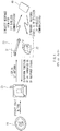
- FIG. 1 is a view illustrating a related art smart key search method.
- the smart key controller 20 of the smart key system senses the operation of the start button 10 and drives the LF antenna 31. Also, the smart key controller 20 transmits a response request signal for authenticating a smart key 40 to the smart key 40 through the LF antenna 31. The smart key 40 transmits a response signal through RF wireless communication.
- the smart key controller 20 controls engine ignition and possibly other functions as well.
- An aspect of the present disclosure provides a smart key searching apparatus and method for searching for a smart key within a vehicle using a wireless charge frequency of a resonant magnetic coupling charging system, rather than using a low frequency (LF) antenna which has been used to search for a smart key in the related art.
- LF low frequency
- a smart key searching apparatus includes: a start button selecting engine start or stop; a wireless charger performing wireless charging in a resonant magnetic coupling manner and transmitting an authentication request signal to a smart key; a radio frequency (RF) receiver receiving a response signal regarding the authentication request signal transmitted from the smart key; and a smart key controller requesting, when the start button is input, the wireless charger to search for a smart key, and controlling power and engine ignition of a vehicle according to a response signal received through the RF receiver.
- RF radio frequency
- the wireless charger may resume the charging operation.
- the wireless charger may determine whether to display a charge state according to a user selection.
- the transmitting of the authentication request signal to the smart key may include: when the wireless charger receives the smart key search request, determining, by the wireless charger, whether the wireless charger is performing a charging operation; and when the wireless charger is performing the charging operation, temporarily stopping the charging operation.
- whether authentication information included in the response signal is valid may be determined, and when the authentication information is valid, power and engine ignition of the vehicle may be controlled.
- the present disclosure is based on the recognition that a smart key search frequency and a charge frequency of a resonant magnetic coupling charging system are the same low frequency (LF) band, in which power, electrical power, and engine ignition of a vehicle are controlled by recognizing a smart key within, or near, the vehicle using a wireless charge frequency of the resonant magnetic coupling charging system without using an existing LF antenna installed within the vehicle.
- LF low frequency
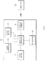
- FIG. 2 is a block diagram illustrating a smart key searching device according to exemplary embodiments of the present disclosure
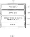
- FIG. 3 is a block diagram schematically illustrating the wireless charger 120 illustrated in FIG. 2
- FIG. 4 is a block diagram schematically illustrating the smart key 200 illustrated in FIG. 2 .
- a smart key searching apparatus 100 is installed within a vehicle and includes a start button 110, a wireless charger 120, a radio frequency (RF) receiver 130, a smart key controller 140, a higher controller 150 and an output device 160.
- RF radio frequency
- the wireless charger 120 wirelessly charges a battery such as a charge target device (e.g., a smart key, a mobile terminal, a tablet PC and/or a notebook computer) in a magnetic resonant coupling manner.
- a charge target device e.g., a smart key, a mobile terminal, a tablet PC and/or a notebook computer
- the charge target device is required to be positioned within a charge available distance (e.g., a few centimeters to a few meters) from the wireless charger 120.
- the wireless charger 120 performs data communication with the smart key controller 140 through a vehicle network.
- the vehicle network is implemented as a controller area network (CAN), a media oriented system transport (MOST) network, a local interconnect network (LIN), X-by-wire (Flexray) and the like.
- the wireless charger 120 searches for a smart key 200 positioned within a reference distance from the vehicle according to a request from the smart key controller 140.
- the wireless charger 120 receives a smart key search request from the smart key controller 140, while wirelessly charging a battery of a charge target device (not shown), the wireless charger 120 temporarily stops wireless charging the battery of the charge target device and performs smart key searching.
- the display 127 may or may not display a charge state according to a user selection.
- the display 127 may receive a user input through an input device (not shown) provided in the wireless charger 120 or may receive a user input through an input device (not shown) provided in the smart key searching apparatus 100.
- the RF receiver 130 performs wireless communication with the smart key 200 at an RF band (e.g., 433 MHz).
- the RF receiver 130 receives an RF signal transmitted from the smart key 200.
- the smart key controller 140 When an input of the start button 110 by a user is sensed, the smart key controller 140 requests the wireless charger 120 to search for a smart key. In other words, when an electrical signal generated by the start button 110 is received according to a user operation, the smart key controller 140 outputs a smart key search request to the wireless charger 120.
- the smart key controller 140 receives a response signal transmitted from the smart key 200 through the RF receiver 130.
- the smart key 200 transmits a response signal including authentication information.
- the authentication information may be an identification number of the smart key 200, e.g., a personal identification number (PIN) or the like.
- the smart key controller 140 determines whether the authentication information included in the received response signal is valid, and controls power and engine ignition of the vehicle according to the authentication determination result. That is, when the authentication information of the smart key 200 is valid, the smart key controller 140 transmits a signal for starting an engine to the higher controller 150.
- the higher controller 150 may be a hybrid control unit (HCU) or an engine electronic control unit (ECU).
- the output device 160 serving to output visual information, audible information and tactile information, may include a display, a speaker, a haptic module and the like.
- the smart key 200 When a smart key authentication request signal is received from the smart key searching apparatus 100, the smart key 200 transmits a response signal in response to the authentication request.
- the smart key 200 includes an LF receiver 201, a controller 203 and an RF transmitter 205, as illustrated in FIG. 4 .
- the LF receiver 201 receives a smart key authentication request signal transmitted from the resonant magnetic coupling transmission coil 125 of the smart key searching apparatus 100. That is, the LF receiver 201 receives an LF signal transmitted from the smart key searching apparatus 100.
- the RF transmitter 205 transmits the response signal through RF wireless communication under the control of the controller 203. In other words, the RF transmitter 205 transmits the response signal including the authentication information output from the controller 203, as an RF signal.
- FIG. 5 is a flowchart illustrating a smart key searching method according to exemplary embodiments of the present disclosure.
- the smart key controller 140 senses an operation of the start button 110 in operation S110. For example, when the user presses the start button 110, the start button 110 generates a corresponding electrical signal. When the electrical signal generated by the start button 110 is received, the smart key controller 140 senses that the start button 110 has been operated.
- the wireless charger 120 determines whether a battery of a charge target device (not shown) is being wirelessly charged in operation S130. In other words, when the smart key search request is received, the wireless charger 120 determines whether an operational state thereof is a charge state.
- the operational state may be a charge state or a smart key search state.
- the wireless charger 120 displays an operational state through the display 127 such that the user (or driver) may recognize an operational state of the wireless charger 120.
- the display 127 may output the operational state in a form of information such as text, an image and/or a symbol.
- the wireless charger 120 drives the charge coils 123 and 125 to request smart key authentication in operation S150.
- the wireless charger 120 drives the charge coils 123 and 125 and transmits a smart key authentication request signal as an LF signal.
- the smart key 200 transmits a response signal in response to the authentication request from the wireless charger 120 in operation S160.
- the smart key 200 transmits the response signal including authentication information of the smart key 200, as an RF signal.
- the smart key controller 140 controls power and the engine according to the response signal from the smart key 200 in operation S170.
- the smart key controller 140 receives a response signal transmitted from the smart key through the RF receiver 130. Also, the smart key controller 140 determines whether the authentication information included in the received response signal is valid. When the authentication information is valid, the smart key controller 140 controls power and engine ignition of the vehicle. However, when the authentication information is not valid, the smart key controller 140 outputs a warning sound and/or a warning message in the form of visual and/or audible information through the output device 160, and ceases the supply of power and blocks engine ignition control of the vehicle.
- the wireless charger 120 resumes charging of the battery of the charge target device in operation S180.
- a predetermined period of time e.g., two seconds
- the wireless charger 120 resumes the charging operation. In other words, the wireless charger 120 transmits wireless power through the charge coil.
- power and engine ignition of the vehicle may be controlled by recognizing the smart key even without the related art LF antenna installed within a vehicle, by utilizing the resonant magnetic coupling charging system.
Landscapes
- Engineering & Computer Science (AREA)
- Mechanical Engineering (AREA)
- Power Engineering (AREA)
- Computer Networks & Wireless Communication (AREA)
- Transportation (AREA)
- Physics & Mathematics (AREA)
- General Physics & Mathematics (AREA)
- Computer Security & Cryptography (AREA)
- Radar, Positioning & Navigation (AREA)
- Remote Sensing (AREA)
- Lock And Its Accessories (AREA)
- Charge And Discharge Circuits For Batteries Or The Like (AREA)
Abstract
Description
- The present disclosure relates to a smart key searching apparatus and method for searching for a smart key using a resonant magnetic coupling charging system.
- In line with the development of electronic control technologies applied to vehicles, technologies such as automatic opening and closing of vehicle doors, automatic engine ignition (or engine start), and the like, using a smart key have been developed. Such a smart key carried by a driver allows for remote opening and closing of a door and engine ignition, maximizing a drivers' convenience.
- A smart key system provided in a vehicle may control engine ignition upon sensing a smart key (fob) positioned in, or near, the vehicle. Here, the smart key system uses two low frequency antennas installed within the vehicle to sense the smart key (fob).
-
FIG. 1 is a view illustrating a related art smart key search method. - A smart key system includes a
start button 10, asmart key controller 20 and atransceiver 30 including a low frequency (LF)antenna 31 and a radio frequency (RF) receiver. - When the
start button 10 is operated (by an input), thesmart key controller 20 of the smart key system senses the operation of thestart button 10 and drives theLF antenna 31. Also, thesmart key controller 20 transmits a response request signal for authenticating asmart key 40 to thesmart key 40 through theLF antenna 31. Thesmart key 40 transmits a response signal through RF wireless communication. - When the response signal is received from the
smart key 40 through theRF receiver 32 and authentication included in the received response signal is valid, thesmart key controller 20 controls engine ignition and possibly other functions as well. - The present disclosure has been made to solve the above-mentioned problems occurring in the prior art while advantages achieved by the prior art are maintained intact.
- An aspect of the present disclosure provides a smart key searching apparatus and method for searching for a smart key within a vehicle using a wireless charge frequency of a resonant magnetic coupling charging system, rather than using a low frequency (LF) antenna which has been used to search for a smart key in the related art.
- According to an exemplary embodiment of the present disclosure, a smart key searching apparatus includes: a start button selecting engine start or stop; a wireless charger performing wireless charging in a resonant magnetic coupling manner and transmitting an authentication request signal to a smart key; a radio frequency (RF) receiver receiving a response signal regarding the authentication request signal transmitted from the smart key; and a smart key controller requesting, when the start button is input, the wireless charger to search for a smart key, and controlling power and engine ignition of a vehicle according to a response signal received through the RF receiver.
- The wireless charger may transmit the authentication request signal at a low frequency (LF) band.
- When the wireless charger receives the smart key search request from the smart key controller, while performing wireless charging, the wireless charger may temporarily stop the charging operation and transmit the authentication request signal.
- When a predetermined period of time has elapsed since transmission of the authentication request signal was completed, the wireless charger may resume the charging operation.
- The wireless charger may display whether the wireless charger is in a charge state or in a smart key search state through a display.
- The wireless charger may determine whether to display a charge state according to a user selection.
- When the authentication request signal is received, the smart key may generate and transmit a response signal including authentication information of the smart key.
- The smart key controller may determine whether the authentication information included in the response signal is valid, and when the authentication information is valid, the smart key controller may control power and engine ignition of the vehicle.
- According to another exemplary embodiment of the present disclosure, a smart key searching method includes: sensing, by a smart key controller, an operation of a start button; when the operation of the start button is sensed, requesting, by the smart key controller, a wireless charger to search for a smart key; driving, by the wireless charger, a charge coil according to the smart key search request and transmitting an authentication request signal to a smart key; transmitting, by the smart key, a response signal in response to the authentication request signal; and when the response signal is received, controlling, by the smart key controller, power and engine ignition of a vehicle according to the received response signal.
- The transmitting of the authentication request signal to the smart key may include: when the wireless charger receives the smart key search request, determining, by the wireless charger, whether the wireless charger is performing a charging operation; and when the wireless charger is performing the charging operation, temporarily stopping the charging operation.
- The method may further include: after the transmitting of the authentication request signal to the smart key, when a predetermined period of time has elapsed since transmission of the authentication request signal was completed, resuming, by the wireless charger, the charging operation.
- In the controlling of power and engine ignition of the vehicle, whether authentication information included in the response signal is valid may be determined, and when the authentication information is valid, power and engine ignition of the vehicle may be controlled.
- The above and other objects, features and advantages of the present disclosure will be more apparent from the following detailed description taken in conjunction with the accompanying drawings.
-
FIG. 1 is a view illustrating a related art method for searching for a smart key. -
FIG. 2 is a block diagram illustrating a smart key searching device according to exemplary embodiments of the present disclosure. -
FIG. 3 is a block diagram schematically illustrating the wireless charger shown inFIG. 2 . -
FIG. 4 is a block diagram schematically illustrating the smart key shown inFIG. 2 . -
FIG. 5 is a flowchart illustrating a smart key searching method according to exemplary embodiments of the present disclosure. - Terms of "comprise" and variations such as "includes", "comprises" or "has" described in this disclosure will be understood to imply the inclusion of stated elements but not the exclusion of any other elements, unless explicitly described to the contrary.
- In addition, the terms "-er", "-or" and "module" described in the specification mean units for processing at least one function and operation and can be implemented by hardware components or software components and combinations thereof. Articles such as "a" or "the" may include plural forms unless referred to the contrary in context describing the present disclosure. Hereinafter, exemplary embodiments of the present disclosure will be described in detail with reference to the accompanying drawings.
- The present disclosure is based on the recognition that a smart key search frequency and a charge frequency of a resonant magnetic coupling charging system are the same low frequency (LF) band, in which power, electrical power, and engine ignition of a vehicle are controlled by recognizing a smart key within, or near, the vehicle using a wireless charge frequency of the resonant magnetic coupling charging system without using an existing LF antenna installed within the vehicle.
-
FIG. 2 is a block diagram illustrating a smart key searching device according to exemplary embodiments of the present disclosure,FIG. 3 is a block diagram schematically illustrating thewireless charger 120 illustrated inFIG. 2 , andFIG. 4 is a block diagram schematically illustrating thesmart key 200 illustrated inFIG. 2 . - In exemplary embodiments, a smart
key searching apparatus 100 is installed within a vehicle and includes astart button 110, awireless charger 120, a radio frequency (RF)receiver 130, asmart key controller 140, ahigher controller 150 and anoutput device 160. - The
start button 110 generates an electrical signal according to a user operation, or input. Thestart button 110 serves to select engine start, engine stop, vehicle power ON, vehicle power OFF or accessory power ON ACC. - The
wireless charger 120 wirelessly charges a battery such as a charge target device (e.g., a smart key, a mobile terminal, a tablet PC and/or a notebook computer) in a magnetic resonant coupling manner. Here, the charge target device is required to be positioned within a charge available distance (e.g., a few centimeters to a few meters) from thewireless charger 120. - The
wireless charger 120 performs data communication with thesmart key controller 140 through a vehicle network. Here, the vehicle network is implemented as a controller area network (CAN), a media oriented system transport (MOST) network, a local interconnect network (LIN), X-by-wire (Flexray) and the like. Thewireless charger 120 searches for asmart key 200 positioned within a reference distance from the vehicle according to a request from thesmart key controller 140. Here, when thewireless charger 120 receives a smart key search request from thesmart key controller 140, while wirelessly charging a battery of a charge target device (not shown), thewireless charger 120 temporarily stops wireless charging the battery of the charge target device and performs smart key searching. - As illustrated in
FIG. 3 , thewireless charger 120 includes apower supply 121, asource coil 123, a magnetic resonantcoupling transmission coil 125 and adisplay 127. Here, thesource coil 123 and the magnetic resonantcoupling transmission coil 125 are collectively referred to as a charge coil. Thepower supply 121 supplies electric power (power) required for an operation of thewireless charger 120. Thepower supply 121 generates an alternating current (AC), and/or a direct current (DC). Thesource coil 123 transfers electric power provided from thepower supply 121 to the magnetic resonantcoupling transmission coil 125. The magnetic resonantcoupling transmission coil 125 generates a magnetic field vibrating at a specific resonance frequency. The magnetic resonantcoupling transmission coil 125 transmits electric power using magnetic field resonance (resonant magnetic coupling). - Also, the magnetic resonant
coupling transmission coil 125 performs wireless communication at a predetermined LF band, e.g., at a 125 kHz band. The magnetic resonantcoupling transmission coil 125 outputs an LF signal (authentication request signal) requesting smart key authentication to search for a smart key. - The
display 127 displays an operational state and a charge state of thewireless charger 120. Here, the operational state is classified as a charge state and a smart key search state (i.e., a state operating as an LF transmission device). The charge state is classified, or termed, as a charging, a charge amount, charge completion and the like. - The
display 127 may or may not display a charge state according to a user selection. Here, thedisplay 127 may receive a user input through an input device (not shown) provided in thewireless charger 120 or may receive a user input through an input device (not shown) provided in the smartkey searching apparatus 100. - The
RF receiver 130 performs wireless communication with thesmart key 200 at an RF band (e.g., 433 MHz). TheRF receiver 130 receives an RF signal transmitted from thesmart key 200. - When an input of the
start button 110 by a user is sensed, the smartkey controller 140 requests thewireless charger 120 to search for a smart key. In other words, when an electrical signal generated by thestart button 110 is received according to a user operation, the smartkey controller 140 outputs a smart key search request to thewireless charger 120. - The smart
key controller 140 receives a response signal transmitted from thesmart key 200 through theRF receiver 130. Thesmart key 200 transmits a response signal including authentication information. Here, the authentication information may be an identification number of thesmart key 200, e.g., a personal identification number (PIN) or the like. - The smart
key controller 140 determines whether the authentication information included in the received response signal is valid, and controls power and engine ignition of the vehicle according to the authentication determination result. That is, when the authentication information of thesmart key 200 is valid, the smartkey controller 140 transmits a signal for starting an engine to thehigher controller 150. - The
higher controller 150 may be a hybrid control unit (HCU) or an engine electronic control unit (ECU). Theoutput device 160, serving to output visual information, audible information and tactile information, may include a display, a speaker, a haptic module and the like. - When a smart key authentication request signal is received from the smart
key searching apparatus 100, thesmart key 200 transmits a response signal in response to the authentication request. Thesmart key 200 includes anLF receiver 201, acontroller 203 and anRF transmitter 205, as illustrated inFIG. 4 . - The
LF receiver 201 receives a smart key authentication request signal transmitted from the resonant magneticcoupling transmission coil 125 of the smartkey searching apparatus 100. That is, theLF receiver 201 receives an LF signal transmitted from the smartkey searching apparatus 100. - When the authentication request signal is received from the
LF receiver 201, thecontroller 203 generates and outputs a corresponding response signal. Thecontroller 203 generates a response signal including the authentication information of thesmart key 200. - The
RF transmitter 205 transmits the response signal through RF wireless communication under the control of thecontroller 203. In other words, theRF transmitter 205 transmits the response signal including the authentication information output from thecontroller 203, as an RF signal. -
FIG. 5 is a flowchart illustrating a smart key searching method according to exemplary embodiments of the present disclosure. - As illustrated in
FIG. 5 , the smartkey controller 140 senses an operation of thestart button 110 in operation S110. For example, when the user presses thestart button 110, thestart button 110 generates a corresponding electrical signal. When the electrical signal generated by thestart button 110 is received, the smartkey controller 140 senses that thestart button 110 has been operated. - When the operation of the
start button 110 is sensed, the smartkey controller 140 requests thewireless charger 120 to search for a smart key in operation S120. The smartkey controller 140 transmits a smart key search request to thewireless charger 120 through a vehicle network. - When the smart key search request is received from the smart
key controller 140, thewireless charger 120 determines whether a battery of a charge target device (not shown) is being wirelessly charged in operation S130. In other words, when the smart key search request is received, thewireless charger 120 determines whether an operational state thereof is a charge state. Here, the operational state may be a charge state or a smart key search state. Thewireless charger 120 displays an operational state through thedisplay 127 such that the user (or driver) may recognize an operational state of thewireless charger 120. Here, thedisplay 127 may output the operational state in a form of information such as text, an image and/or a symbol. - When the
wireless charger 120 is performing wireless charging, thewireless charger 120 temporarily stops the charge operation in operation S140. Thewireless charger 120 stops transmitting a wireless charge frequency (LF signal) through the charge coils 123 and 125. That is, thewireless charger 120 stops supplying wireless power to stop charging the battery of the charge target device for a predetermined period of time. - The
wireless charger 120 drives the charge coils 123 and 125 to request smart key authentication in operation S150. Thewireless charger 120 drives the charge coils 123 and 125 and transmits a smart key authentication request signal as an LF signal. - The
smart key 200 transmits a response signal in response to the authentication request from thewireless charger 120 in operation S160. Thesmart key 200 transmits the response signal including authentication information of thesmart key 200, as an RF signal. - The smart
key controller 140 controls power and the engine according to the response signal from thesmart key 200 in operation S170. The smartkey controller 140 receives a response signal transmitted from the smart key through theRF receiver 130. Also, the smartkey controller 140 determines whether the authentication information included in the received response signal is valid. When the authentication information is valid, the smartkey controller 140 controls power and engine ignition of the vehicle. However, when the authentication information is not valid, the smartkey controller 140 outputs a warning sound and/or a warning message in the form of visual and/or audible information through theoutput device 160, and ceases the supply of power and blocks engine ignition control of the vehicle. - Meanwhile, after transmitting the smart key authentication request in operation S150, the
wireless charger 120 resumes charging of the battery of the charge target device in operation S180. Here, when a predetermined period of time (e.g., two seconds) has elapsed since the smart key authentication request was completed, thewireless charger 120 resumes the charging operation. In other words, thewireless charger 120 transmits wireless power through the charge coil. - As described above, according to exemplary embodiments of the present disclosure, power and engine ignition of the vehicle may be controlled by recognizing the smart key even without the related art LF antenna installed within a vehicle, by utilizing the resonant magnetic coupling charging system.
- In addition, since a smart key may be searched without an LF antenna, an LF antenna within the vehicle may be eliminated. Thus, costs may be reduced and the same merchantable quality may be maintained.
- Even though all of elements of exemplary embodiments according to the present disclosure have been described as being coupled or as being coupled and operating as one element, the present disclosure is not limited to the exemplary embodiments. That is, to the extent of the purpose of the present disclosure, all of such elements may be selectively coupled and operate as one or more elements. Such elements may be realized as individual hardware components, but all or part of such elements may be selectively combined into a computer program having a program module performing partial or all functions combined by a single or a plurality of hardware. Codes and code segments forming the computer program may be easily inferred by a person of ordinary skill in the art of the present disclosure. Such computer program may be stored in computer readable media read by a computer, and may be read and executed by the computer to thereby realize the exemplary embodiments of the present disclosure.
- Hereinabove, although the present disclosure has been described with reference to exemplary embodiments and the accompanying drawings, the present disclosure is not limited thereto, but may be variously modified and altered by those skilled in the art to which the present disclosure pertains without departing from the spirit and scope of the present disclosure claimed in the following claims.
-
- 110: START BUTTON
- 120: WIRELESS CHARGER
- 130: RF RECEIVER
- 140: SMART KEY CONTROLLER
- 150: HIGHER CONTROLLER
- 160: OUTPUT DEVICE
- 200: SMART KEY
- 121: POWER SUPPLY
- 123: SOURCE COIL
- 125: RESONANT MAGNETIC COUPLING TRANSMISSION COIL
- 127: DISPLAY
- 201: LF RECEIVER
- 203: CONTROLLER
- 205: RF TRANSMITTER
- S110: SENSE OPERATION OF START BUTTON
- S120: REQUEST WIRELESS CHARGER TO SEARCH FOR SMART KEY
- S130: WIRELESS CHARGER IS PERFORMING CHARGING OPERATION?
- S140: TEMPORARILY STOP CHARGING OPERATION OF WIRELESS CHARGER
- S150: REQUEST SMART KEY AUTHENTICATION BY DRIVING RESONANT MAGNETIC COUPLING TRANSMISSION COIL OF WIRELESS CHARGER
- S160: TRANSMIT RESPONSE SIGNAL BY SMART KEY IN RESPONSE TO AUTHENTICATION REQUEST
- S170: CONTROL POWER AND ENGINE IGNITION ACCORDING TO RESPONSE SIGNAL FROM SMART KEY
- S180: RESUME CHARGING OPERATION OF WIRELESS CHARGER
Claims (12)
- A smart key searching apparatus comprising:a start button for selecting engine start or stop;a wireless charger performing wireless charging in a resonant magnetic coupling manner and transmitting an authentication request signal to a smart key;a radio frequency (RF) receiver receiving a response signal regarding the authentication request signal transmitted from the smart key; anda smart key controller requesting, when the start button is operated, the wireless charger to search for a smart key, and controlling power and engine ignition of a vehicle according to a response signal received through the RF receiver.
- The smart key searching apparatus according to claim 1, wherein the wireless charger transmits the authentication request signal in a low frequency (LF) band.
- The smart key searching apparatus according to claim 1, wherein when the wireless charger receives the smart key search request from the smart key controller, while performing wireless charging, the wireless charger temporarily stops the charging operation and transmits the authentication request signal.
- The smart key searching apparatus according to claim 3, wherein when a predetermined period of time has elapsed since the transmission of the authentication request signal was completed, the wireless charger resumes the charging operation.
- The smart key searching apparatus according to claim 1, wherein the wireless charger displays whether the wireless charger is in a charge state or in a smart key search state via a display.
- The smart key searching apparatus according to claim 1, wherein the wireless charger determines whether to display a charge state according to a user selection.
- The smart key searching apparatus according to claim 1, wherein when the authentication request signal is received, the smart key generates and transmits a response signal including authentication information of the smart key.
- The smart key searching apparatus according to claim 1, wherein the smart key controller determines whether the authentication information included in the response signal is valid, and when the authentication information is determined to be valid, the smart key controller controls power and engine ignition of the vehicle.
- A smart key searching method comprising:sensing, by a smart key controller, an operation of a start button;when the operation of the start button is sensed, requesting, by the smart key controller, a wireless charger to search for a smart key;driving, by the wireless charger, a charge coil according to the smart key search request and transmitting an authentication request signal to a smart key;transmitting, by the smart key, a response signal in response to the authentication request signal; andwhen the response signal is received, controlling, by the smart key controller, power and engine ignition of a vehicle according to the received response signal.
- The smart key searching method according to claim 9, wherein the transmitting of the authentication request signal to the smart key includes:when the wireless charger receives the smart key search request, determining, by the wireless charger, whether the wireless charger is performing a charging operation; andwhen the wireless charger is determined to be performing the charging operation, temporarily stopping the charging operation.
- The smart key searching method according to claim 10, further comprising: after the step of transmitting the authentication request signal to the smart key, when a predetermined period of time has elapsed since the transmission of the authentication request signal was completed, resuming, by the wireless charger, the charging operation.
- The smart key searching method according to claim 9, wherein, in the step of controlling power and engine ignition of the vehicle, whether authentication information included in the response signal is valid is determined, and when the authentication information is determined to be valid, power and engine ignition of the vehicle are controlled.
Applications Claiming Priority (1)
| Application Number | Priority Date | Filing Date | Title |
|---|---|---|---|
| KR1020160116607A KR20180028803A (en) | 2016-09-09 | 2016-09-09 | Apparatus and method for searching smart key |
Publications (1)
| Publication Number | Publication Date |
|---|---|
| EP3293706A1 true EP3293706A1 (en) | 2018-03-14 |
Family
ID=57754916
Family Applications (1)
| Application Number | Title | Priority Date | Filing Date |
|---|---|---|---|
| EP16201687.7A Withdrawn EP3293706A1 (en) | 2016-09-09 | 2016-12-01 | Smart key searching apparatus and method |
Country Status (4)
| Country | Link |
|---|---|
| US (1) | US20180072268A1 (en) |
| EP (1) | EP3293706A1 (en) |
| KR (1) | KR20180028803A (en) |
| CN (1) | CN107804277A (en) |
Cited By (3)
| Publication number | Priority date | Publication date | Assignee | Title |
|---|---|---|---|---|
| WO2019224152A1 (en) * | 2018-05-24 | 2019-11-28 | Valeo Comfort And Driving Assistance | Passive entry passive start device providing wireless charger resources and method to operate such a device |
| CN112673607A (en) * | 2019-07-03 | 2021-04-16 | 谷歌有限责任公司 | Anonymous device authentication |
| CN112959972A (en) * | 2021-03-23 | 2021-06-15 | 一汽奔腾轿车有限公司 | Positioning judgment system and method for intelligent key under mobile phone interference condition |
Families Citing this family (11)
| Publication number | Priority date | Publication date | Assignee | Title |
|---|---|---|---|---|
| US20180298670A1 (en) * | 2017-04-13 | 2018-10-18 | Ford Global Technologies, Llc | Vehicle hands-free closure initializer |
| CN110525378B (en) * | 2018-05-24 | 2023-06-06 | 法雷奥舒适驾驶助手公司 | PEPS device providing wireless charger resources and method for operating the same |
| US20190386513A1 (en) * | 2018-06-14 | 2019-12-19 | Integrated Device Technology, Inc. | Bi-directional communication in wireless power transmission |
| JP7063141B2 (en) * | 2018-06-21 | 2022-05-09 | 株式会社Soken | Portable device position estimation system |
| CN109494828A (en) * | 2018-10-17 | 2019-03-19 | 北京车和家信息技术有限公司 | Charging control method, remote control key and vehicle |
| US10848954B1 (en) * | 2019-09-06 | 2020-11-24 | Ford Global Technologies, Llc | Conditional repetitive wireless device searching |
| CN112744180B (en) * | 2019-10-29 | 2023-04-28 | 现代自动车株式会社 | System and method for connected vehicle control |
| CN112863151B (en) * | 2021-01-28 | 2023-06-16 | 大陆汽车电子(长春)有限公司 | Method and system for preventing intelligent key from being damaged by vehicle-mounted wireless charger |
| JP7812713B2 (en) * | 2022-03-31 | 2026-02-10 | 株式会社デンソーテン | Communication device, smart key device, smart key system, and communication method |
| CN115410299B (en) * | 2022-08-24 | 2025-01-03 | 长城汽车股份有限公司 | Vehicle starting method, electronic device and storage medium |
| CN115882903B (en) * | 2022-12-06 | 2024-09-20 | 中国第一汽车股份有限公司 | Vehicle starting method, device, equipment and medium |
Citations (5)
| Publication number | Priority date | Publication date | Assignee | Title |
|---|---|---|---|---|
| EP1336939A2 (en) * | 2002-02-15 | 2003-08-20 | Alps Electric Co., Ltd. | Vehicle-mounted device communication controller |
| EP2020346A2 (en) * | 2007-07-30 | 2009-02-04 | Jae Woo Yang | Apparatus and method for starting engine of automobile using start-button |
| JP2013138529A (en) * | 2011-12-28 | 2013-07-11 | Seiko Epson Corp | Electronic apparatus, charging device and charging system |
| EP2736207A1 (en) * | 2011-07-21 | 2014-05-28 | LG Electronics Inc. | Communication of wireless power receiver through wireless power signal |
| WO2015194889A1 (en) * | 2014-06-20 | 2015-12-23 | Lg Electronics Inc. | Wireless power transfer method, apparatus and system |
Family Cites Families (2)
| Publication number | Priority date | Publication date | Assignee | Title |
|---|---|---|---|---|
| JP6162653B2 (en) * | 2014-06-25 | 2017-07-12 | 本田技研工業株式会社 | Wireless charging system |
| CN105701886A (en) * | 2014-11-26 | 2016-06-22 | 鸿富锦精密工业(深圳)有限公司 | Intelligent key system |
-
2016
- 2016-09-09 KR KR1020160116607A patent/KR20180028803A/en not_active Ceased
- 2016-11-30 US US15/364,936 patent/US20180072268A1/en not_active Abandoned
- 2016-12-01 CN CN201611093889.8A patent/CN107804277A/en active Pending
- 2016-12-01 EP EP16201687.7A patent/EP3293706A1/en not_active Withdrawn
Patent Citations (5)
| Publication number | Priority date | Publication date | Assignee | Title |
|---|---|---|---|---|
| EP1336939A2 (en) * | 2002-02-15 | 2003-08-20 | Alps Electric Co., Ltd. | Vehicle-mounted device communication controller |
| EP2020346A2 (en) * | 2007-07-30 | 2009-02-04 | Jae Woo Yang | Apparatus and method for starting engine of automobile using start-button |
| EP2736207A1 (en) * | 2011-07-21 | 2014-05-28 | LG Electronics Inc. | Communication of wireless power receiver through wireless power signal |
| JP2013138529A (en) * | 2011-12-28 | 2013-07-11 | Seiko Epson Corp | Electronic apparatus, charging device and charging system |
| WO2015194889A1 (en) * | 2014-06-20 | 2015-12-23 | Lg Electronics Inc. | Wireless power transfer method, apparatus and system |
Cited By (6)
| Publication number | Priority date | Publication date | Assignee | Title |
|---|---|---|---|---|
| WO2019224152A1 (en) * | 2018-05-24 | 2019-11-28 | Valeo Comfort And Driving Assistance | Passive entry passive start device providing wireless charger resources and method to operate such a device |
| CN112673607A (en) * | 2019-07-03 | 2021-04-16 | 谷歌有限责任公司 | Anonymous device authentication |
| CN112673607B (en) * | 2019-07-03 | 2023-04-04 | 谷歌有限责任公司 | Anonymous device authentication |
| US12003964B2 (en) | 2019-07-03 | 2024-06-04 | Google Llc | Anonymous device authentication |
| US12250546B2 (en) | 2019-07-03 | 2025-03-11 | Google Llc | Anonymous device authentication |
| CN112959972A (en) * | 2021-03-23 | 2021-06-15 | 一汽奔腾轿车有限公司 | Positioning judgment system and method for intelligent key under mobile phone interference condition |
Also Published As
| Publication number | Publication date |
|---|---|
| US20180072268A1 (en) | 2018-03-15 |
| KR20180028803A (en) | 2018-03-19 |
| CN107804277A (en) | 2018-03-16 |
Similar Documents
| Publication | Publication Date | Title |
|---|---|---|
| US20180072268A1 (en) | Smart key searching apparatus and method | |
| US8878661B2 (en) | Information communication system and vehicle portable device | |
| US20190202401A1 (en) | Device and method for controlling vehicle | |
| KR101902795B1 (en) | Method for wireless charging and apparatus for the same | |
| US20130285603A1 (en) | Universal wireless charging system for motor vehicles | |
| US10157542B2 (en) | User identification system and vehicular portable device | |
| JP5720501B2 (en) | In-vehicle mobile terminal charger | |
| US9509496B2 (en) | Electronic key registration system | |
| JP6162653B2 (en) | Wireless charging system | |
| CN105303653A (en) | Phone sleeve vehicle fob | |
| EP2716502A1 (en) | Vehicle communication apparatus | |
| CN104106192A (en) | Wireless charging device and method for controlling wireless charging | |
| CN102194076A (en) | Method and system for authorizing a vehicle driveaway | |
| US11284232B2 (en) | Vehicle control system | |
| CN110944884B (en) | Mobile identification transmitter | |
| KR20160049293A (en) | Wireless charging system, wireless charging apparatus and emergency ignition method thereof | |
| CN104442620A (en) | Vehicular wireless control system, control method of vehicular wireless control system and vehicular transmitting terminal | |
| CN204586742U (en) | The startup control system of automobile | |
| KR20150011031A (en) | Smart Key System and Method Thereof | |
| WO2019195703A1 (en) | Wireless chargers and mobile phones in vehicles | |
| JP2017172563A (en) | On-vehicle control system and portable machine | |
| US10798550B2 (en) | Terminal device, method of controlling terminal device, and program | |
| CN109693642B (en) | Vehicle-mounted device and mobile terminal | |
| KR102300650B1 (en) | Smart key and method for preventing discharge of battery for smart key | |
| CN114865746A (en) | Wireless charging system and vehicle |
Legal Events
| Date | Code | Title | Description |
|---|---|---|---|
| PUAI | Public reference made under article 153(3) epc to a published international application that has entered the european phase |
Free format text: ORIGINAL CODE: 0009012 |
|
| STAA | Information on the status of an ep patent application or granted ep patent |
Free format text: STATUS: REQUEST FOR EXAMINATION WAS MADE |
|
| 17P | Request for examination filed |
Effective date: 20180111 |
|
| AK | Designated contracting states |
Kind code of ref document: A1 Designated state(s): AL AT BE BG CH CY CZ DE DK EE ES FI FR GB GR HR HU IE IS IT LI LT LU LV MC MK MT NL NO PL PT RO RS SE SI SK SM TR |
|
| AX | Request for extension of the european patent |
Extension state: BA ME |
|
| STAA | Information on the status of an ep patent application or granted ep patent |
Free format text: STATUS: EXAMINATION IS IN PROGRESS |
|
| 17Q | First examination report despatched |
Effective date: 20210226 |
|
| STAA | Information on the status of an ep patent application or granted ep patent |
Free format text: STATUS: THE APPLICATION IS DEEMED TO BE WITHDRAWN |
|
| 18D | Application deemed to be withdrawn |
Effective date: 20220701 |