EP3293679A2 - Switchable, oscillating near-field and far-field antenna - Google Patents
Switchable, oscillating near-field and far-field antenna Download PDFInfo
- Publication number
- EP3293679A2 EP3293679A2 EP17183681.0A EP17183681A EP3293679A2 EP 3293679 A2 EP3293679 A2 EP 3293679A2 EP 17183681 A EP17183681 A EP 17183681A EP 3293679 A2 EP3293679 A2 EP 3293679A2
- Authority
- EP
- European Patent Office
- Prior art keywords
- field
- antenna
- far
- rfid tag
- access control
- Prior art date
- Legal status (The legal status is an assumption and is not a legal conclusion. Google has not performed a legal analysis and makes no representation as to the accuracy of the status listed.)
- Granted
Links
- 238000000034 method Methods 0.000 claims abstract description 32
- 230000004913 activation Effects 0.000 claims description 10
- 238000012545 processing Methods 0.000 description 20
- 230000015654 memory Effects 0.000 description 15
- 238000013475 authorization Methods 0.000 description 9
- 230000010355 oscillation Effects 0.000 description 9
- 230000006870 function Effects 0.000 description 7
- 230000010287 polarization Effects 0.000 description 6
- 230000008569 process Effects 0.000 description 6
- 230000005540 biological transmission Effects 0.000 description 5
- 238000004891 communication Methods 0.000 description 5
- 238000005516 engineering process Methods 0.000 description 5
- 230000004044 response Effects 0.000 description 5
- 230000000875 corresponding effect Effects 0.000 description 4
- 230000033001 locomotion Effects 0.000 description 4
- 230000008901 benefit Effects 0.000 description 3
- 230000008859 change Effects 0.000 description 3
- 238000000926 separation method Methods 0.000 description 3
- 239000000470 constituent Substances 0.000 description 2
- 230000003993 interaction Effects 0.000 description 2
- 230000007246 mechanism Effects 0.000 description 2
- 239000007787 solid Substances 0.000 description 2
- 230000003068 static effect Effects 0.000 description 2
- 230000002159 abnormal effect Effects 0.000 description 1
- 230000009471 action Effects 0.000 description 1
- 238000013459 approach Methods 0.000 description 1
- 230000001010 compromised effect Effects 0.000 description 1
- 230000001276 controlling effect Effects 0.000 description 1
- 230000002596 correlated effect Effects 0.000 description 1
- 230000008878 coupling Effects 0.000 description 1
- 238000010168 coupling process Methods 0.000 description 1
- 238000005859 coupling reaction Methods 0.000 description 1
- 230000007423 decrease Effects 0.000 description 1
- 230000001934 delay Effects 0.000 description 1
- 238000013461 design Methods 0.000 description 1
- 238000001514 detection method Methods 0.000 description 1
- 238000010586 diagram Methods 0.000 description 1
- 230000000694 effects Effects 0.000 description 1
- 230000001747 exhibiting effect Effects 0.000 description 1
- 239000000284 extract Substances 0.000 description 1
- 230000000977 initiatory effect Effects 0.000 description 1
- 238000002955 isolation Methods 0.000 description 1
- 238000002372 labelling Methods 0.000 description 1
- 230000000670 limiting effect Effects 0.000 description 1
- 238000012544 monitoring process Methods 0.000 description 1
- 230000006855 networking Effects 0.000 description 1
- 230000003287 optical effect Effects 0.000 description 1
- 230000036961 partial effect Effects 0.000 description 1
- 230000002093 peripheral effect Effects 0.000 description 1
- 230000002829 reductive effect Effects 0.000 description 1
- 238000012795 verification Methods 0.000 description 1
Images


Classifications
-
- H—ELECTRICITY
- H01—ELECTRIC ELEMENTS
- H01Q—ANTENNAS, i.e. RADIO AERIALS
- H01Q7/00—Loop antennas with a substantially uniform current distribution around the loop and having a directional radiation pattern in a plane perpendicular to the plane of the loop
-
- G—PHYSICS
- G06—COMPUTING; CALCULATING OR COUNTING
- G06K—GRAPHICAL DATA READING; PRESENTATION OF DATA; RECORD CARRIERS; HANDLING RECORD CARRIERS
- G06K19/00—Record carriers for use with machines and with at least a part designed to carry digital markings
- G06K19/06—Record carriers for use with machines and with at least a part designed to carry digital markings characterised by the kind of the digital marking, e.g. shape, nature, code
- G06K19/067—Record carriers with conductive marks, printed circuits or semiconductor circuit elements, e.g. credit or identity cards also with resonating or responding marks without active components
- G06K19/07—Record carriers with conductive marks, printed circuits or semiconductor circuit elements, e.g. credit or identity cards also with resonating or responding marks without active components with integrated circuit chips
- G06K19/077—Constructional details, e.g. mounting of circuits in the carrier
-
- G—PHYSICS
- G06—COMPUTING; CALCULATING OR COUNTING
- G06K—GRAPHICAL DATA READING; PRESENTATION OF DATA; RECORD CARRIERS; HANDLING RECORD CARRIERS
- G06K7/00—Methods or arrangements for sensing record carriers, e.g. for reading patterns
- G06K7/10—Methods or arrangements for sensing record carriers, e.g. for reading patterns by electromagnetic radiation, e.g. optical sensing; by corpuscular radiation
- G06K7/10009—Methods or arrangements for sensing record carriers, e.g. for reading patterns by electromagnetic radiation, e.g. optical sensing; by corpuscular radiation sensing by radiation using wavelengths larger than 0.1 mm, e.g. radio-waves or microwaves
- G06K7/10316—Methods or arrangements for sensing record carriers, e.g. for reading patterns by electromagnetic radiation, e.g. optical sensing; by corpuscular radiation sensing by radiation using wavelengths larger than 0.1 mm, e.g. radio-waves or microwaves using at least one antenna particularly designed for interrogating the wireless record carriers
- G06K7/10356—Methods or arrangements for sensing record carriers, e.g. for reading patterns by electromagnetic radiation, e.g. optical sensing; by corpuscular radiation sensing by radiation using wavelengths larger than 0.1 mm, e.g. radio-waves or microwaves using at least one antenna particularly designed for interrogating the wireless record carriers using a plurality of antennas, e.g. configurations including means to resolve interference between the plurality of antennas
-
- H—ELECTRICITY
- H01—ELECTRIC ELEMENTS
- H01Q—ANTENNAS, i.e. RADIO AERIALS
- H01Q1/00—Details of, or arrangements associated with, antennas
- H01Q1/12—Supports; Mounting means
- H01Q1/22—Supports; Mounting means by structural association with other equipment or articles
- H01Q1/2208—Supports; Mounting means by structural association with other equipment or articles associated with components used in interrogation type services, i.e. in systems for information exchange between an interrogator/reader and a tag/transponder, e.g. in Radio Frequency Identification [RFID] systems
-
- H04B5/70—
-
- H—ELECTRICITY
- H04—ELECTRIC COMMUNICATION TECHNIQUE
- H04W—WIRELESS COMMUNICATION NETWORKS
- H04W4/00—Services specially adapted for wireless communication networks; Facilities therefor
- H04W4/02—Services making use of location information
- H04W4/025—Services making use of location information using location based information parameters
Definitions
- the present technology pertains to radio frequency (RF) antennas, and more specifically pertains to switchable near-field and far-field RF antennas.
- RF radio frequency
- Radio frequency (RF) signals are often used in RFID systems in order to communicate with one or more tags, for purposes such as security or tracking.
- an RFID system uses a transceiver to broadcast an interrogation signal, which is received by any operable RFID tag within the operable range of the transceiver.
- each RFID tag Upon receiving the interrogation signal, each RFID tag transmits a response signal that encodes unique tag identification information and other stored data.
- RFID tags can be classified as either passive or active, depending on how they are powered - passive RFID tags are powered via an onboard DC converter that extracts energy from the interrogation signal, and active RFID tags are powered by an onboard battery.
- simply receiving a response signal is sufficient, as it indicates that the RFID tag (and any person or object associated with the tag) corresponding to the response signal is located within the boundaries defined by the range of the RFID transceiver. Greater granularity may be provided by transmitting each response signal at a known signal strength, given that signal strength decreases in a predictable manner. As such, the distance between the RFID transceiver and a source tag can be approximated by analyzing the signal strength of the response signal received at the transceiver.
- RFID systems may be divided into near-field systems and far-field systems, each exhibiting unique properties and requiring a specific type of antenna.
- the most immediately observable distinction between near-field and far-field is the separation range between tag and transceiver over which the RFID system remains operable.
- Near-field systems often found in card readers and other close proximity applications, are constrained to a separation on the order of inches and are polarization agnostic.
- Far-field systems often found in asset or product tracking applications, operate at a separation on the order of feet and are polarization sensitive (unable to obtain a reading), particularly at close range.
- an access control system comprising: a controller and a transceiver coupled to the controller, wherein the transceiver comprises an antenna module including a near-field antenna and a far-field antenna, and wherein the near-field antenna is a subset of the far-field antenna.
- the controller is configured to, using the transceiver, scan an RFID tag of a wireless asset and receive one or more return signals from the RFID tag, and determine a location of the wireless asset based on the one or more return signals.
- the controller is configured to receive two or more return signals from the RFID tag and determine a direction of the wireless asset based on the two or more return signals.
- the access control system further transmits position information corresponding with one or more of the location of the wireless asset and the direction of the wireless asset to a cloud controller, wherein the cloud controller is configured to receive position information from a plurality of networked asset control systems.
- scanning the RFID tag further comprises oscillating the antenna module between a near-field scanning mode and a far-field scanning mode, wherein the near-field scanning mode corresponds with activation of the near-field antenna, and the far-field scanning mode corresponds with activation of the far-field antenna.
- the return signal comprises signal strength and phase information associated with the RFID tag.
- the near-field antenna is a UHF near-field loop antenna.
- Disclosed is a method for tracking a wireless asset comprising scanning, using a transceiver, an RFID tag of a wireless asset, wherein the transceiver comprises an antenna module including a near-field antenna and a far-field antenna, receiving one or more return signals from the RFID tag, and determining a location of the wireless asset based on the one or more return signals.
- the near-field antenna is a subset of the far-field antenna.
- the method further comprises receiving two or more return signals from the RFID tag and determining a direction of the wireless asset based on the two or more return signals.
- the method further comprises transmitting position information corresponding with one or more of the location of the wireless asset and a direction of the wireless asset to a cloud controller, wherein the cloud controller is configured to receive position information from a plurality of networked asset control systems.
- scanning the RFID tag further comprises oscillating the antenna module between a near-field scanning mode and a far-field scanning mode, wherein the near-field scanning mode corresponds with activation of the near-field antenna, and wherein the far-field scanning mode corresponds with activation of the far-field antenna.
- the return signal comprises signal strength and phase information associated with the RFID tag.
- Non-transitory computer-readable storage medium comprising instructions stored therein, which when executed by one or more processors, cause the processors to perform operations comprising scanning, using a transceiver, an RFID tag of a wireless asset, wherein the transceiver comprises an antenna module including a near-field antenna and a far-field antenna, receiving one or more return signals from the RFID tag, and determining a location of the wireless asset based on the one or more return signals.
- the near-field antenna is a subset of the far-field antenna.
- the processor is further configured to perform operations comprising receiving two or more return signals from the RFID tag and determining a direction of the wireless asset based on the two or more return signals.
- the processor is further configured to perform operations comprising transmitting position information corresponding with one or more of the location of the wireless asset and a direction of the wireless asset to a cloud controller, wherein the cloud controller is configured to receive position information from a plurality of networked asset control systems.
- scanning the RFID tag further comprises oscillating the antenna module between a near-field scanning mode and a far-field scanning mode, wherein the near-field scanning mode corresponds with activation of the near-field antenna, and wherein the far-field scanning mode corresponds with activation of the far-field antenna.
- the return signal comprises signal strength and phase information associated with the RFID tag.
- the near-field antenna is a UHF near-field loop antenna.
- FIG. 1 depicts an illustrative schematic diagram of an access control system 100 and its constituent components.
- the access control system may be broken down into three constituent components: a cloud controller 102, some number n of access control readers 110a-110n, and a plurality of wireless assets 120 (illustrated here as RFID tags, although it is understood that a variety of other radio-frequency (RF) devices or wireless identification tags may be used).
- RF radio-frequency
- access control system 100 is not illustrated with respect to any specific implementation, by means of example, such an access control system may be used for purposes such as asset tracking in a factory, warehouse, or other commercial building, wherein integrated or externally attached RFID tags are used to track the flow of packages or other goods, or for a building security system, wherein RFID tags are embedded into identification cards and used to verify and grant individual access to locked doors or other secured assets.
- cloud controller 102 is communicatively coupled with each of the access control readers 110a-110n via a direct link, although in some embodiments, cloud controller 102 may be communicatively coupled with one or more of the access control readers 110a-110n via an indirect link, wherein one or more intermediate nodes or access control readers are communicatively coupled between cloud controller 102 and the destination access control reader.
- communicatively coupled is understood to mean any data transmission link between two or more computing devices or components, wired or wireless. Examples of such data transmission links include, but are not limited to, a Local Area Network (LAN), a Wide Area Network (WAN), Intranet, Internet, or any other wired or wireless networking and data transmission technologies that are known in the art.
- cloud controller 102 and the access control readers 110a-110n may be provided separately, in order to provide increased security and reliability.
- cloud controller 102 may be located on a separate network from that of the access control readers 110a-110n, such that both networks much be breached or otherwise compromised in order for access control system 100 to be defeated.
- cloud controller 102 may be physically remote from access control readers 110a-110n, which can increase security and provide greater operational flexibility by allowing the access control system 100 to be operated and monitored constantly, for example through a secure web portal or web application.
- cloud controller 102 is provided in a tiered hierarchy, such that it is above each of the access control readers 110a-110n.
- cloud controller 102 and the access control readers 110a-110n can exist in a master-slave relationship, wherein cloud controller 102 oversees all aspects of operation for each of the access control readers.
- cloud controller 102 is not limited to such a master-slave relationship, and it is understood that the access control readers may be capable of a partial or total degree of autonomy in their operation (provided, for example, via controller 112 contained within access control reader 110a), such that cloud controller 102 only assumes a supervisory role, such as monitoring for any abnormal events or other deviations from expected operation.
- Cloud controller 102 may be provided on a single computing device, such as a computer server, or cloud controller 102 may be provided across a plurality of different computing devices that comprise, for example, a cloud computing cluster.
- cloud controller 102 may be implemented as a central processing unit (CPU), a microcontroller (MCU), a microprocessor, integrated circuitry, or any other controller known in the art.
- cloud controller 102 may be connected to a database (not shown) that can store historical records of each interaction between the plurality of RFID tags 120 and the access control readers 110a-110n.
- the database may also be used to store one or more access control policies, with a specific access control policy being manually selectable (and editable) by an administrator of access control system 100, or being automatically selectable according to one or more pre-defined rules, based on criteria such as time or location.
- access control readers 110a-110n contains some number n of access control readers, that may be physically identically or otherwise capable of providing substantially similar functionality. Each access control reader may be associated with a certain access point, and any given access point may be associated with one or more access control readers. As depicted in FIG. 1 , each of the access control readers 110a-110n is illustrated in an identical schematic form, and the following description will be made with reference to access control reader 110a, but is extensible to each of the access control readers 110a-110n.
- Access control reader 110a consists of three primary components: a controller 112, a transceiver 114, and a far-field antenna 116.
- a near-field antenna 118 is formed from a subset of far-field antenna 116, as will be subsequently explained in greater depth.
- Controller 112 may be provided by a processing element, capable of implementing programmed commands that may be edited or modified by an administrator of access control system 100. In some embodiments, controller 112 may simply receive one or more control commands from cloud controller 102 and execute them accordingly.
- transceiver 114 is coupled to controller 112, and is capable of transmitting and receiving RF or other electromagnetic (EM) signals, as is understood by one of ordinary skill in the art.
- the signal processing required to support this transmitting and receiving functionality may be performed by a processing element of controller 112 or a processing element of cloud controller 102
- transceiver 114 may contain its own signal processing element, particularly in a large access control system where it may be impractical to perform signal processing at controller 112 or cloud controller 102.
- Transceiver 114 is further coupled to far-field antenna 116, which is used to interact with one or more of the plurality of RFID tags.
- far-field antenna 116 has an operable range of up to 30 feet, although it is understood that the operable range of far-field antenna 116 may depend upon a number of different factors such as the operating wavelength of access control system 100, the physical geometry of the access point at which far-field antenna 116 is located, the polarization of access control reader 110a and the polarization of a given RFID tag.
- Near-field antenna 118 is formed from a subset of far-field antenna 116, which may be achieved by selectively energizing a certain portion of far-field antenna 116, as will be explained with respect to FIG. 2 . This selective energization may be controlled by controller 112, cloud controller 102, or some combination of the two. When near-field antenna 118 is energized, it may have an operational range of approximately 18 inches, although once again, it is understood that this operable range may depend upon a number of different factors as would be appreciated by one of ordinary skill in the art. Each of far-field antenna 116 and near-field antenna 118 may interact with one or more of the plurality of RFID tags 120 in order to perform a read operation, and multiple RFID tags may be read simultaneously. In one aspect of the disclosure, access control reader 110a may oscillate between energizing far-field antenna 116 and energizing near-field antenna 118, in order to provide an improved and more reliable tracking of the plurality of RFID tags 120.
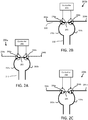
- FIG. 2A-2C three different antenna configurations are illustrated, wherein each of the distinct antenna configurations can be achieved using the same set of physical antenna components, as indicated by the numerical labeling common to the three figures.
- each configuration is presented in a simplified diagrammatic form, wherein a solid line indicates an energized antenna portion and a dashed line indicates a non-energized antenna portion.
- FIG. 2A depicts a near-field antenna configuration 200a, wherein only a near-field loop antenna is energized.
- FIG. 2B depicts a combined near-field and far-field antenna configuration 200b, in which a near-field loop antenna and a far-field antenna are energized.
- FIG. 2C depicts a far-field antenna configuration 200c, wherein only a far-field loop antenna is energized.
- access control reader 110a may oscillate between near-field antenna configuration 200a and combined near-field and far-field antenna configuration 200b. In a second embodiment, access control reader 110a may oscillate between near-field antenna configuration 200a and far-field antenna configuration 200c. The oscillation may take place on the order of 20-200 Hz, wherein a greater oscillation frequency can provide a greater resolution with respect to the movement and position of a given RFID tag in the vicinity of access control reader 110a, although it is understood that other oscillation frequencies may be implemented as needed or as desired for a given application.
- oscillation controller 208 which is coupled to switches 206a and 206b in order to selectively energize the desired antenna components.
- Switches 206a and 206b may be mechanical or solid-state switches, depending on the specific application in which they are used.
- Oscillation controller 208 may be provided by controller 112 or by cloud controller 102, as explained previously. Oscillation controller 208 may also be a standalone component, equipped to receive control or timing commands from one or more of controller 112 and cloud controller 102.
- switches 206a and 206b are positioned such that only a near-field loop antenna 210 is energized, wherein near-field loop antenna 210 is formed from a series connection between first loop portion 202a, a bridge portion 205, and a second loop portion 202b.
- FIG. 2A depicts only a single near-field loop antenna 210, some embodiments may make use of one or more near-field loop antennas.
- the one or more near-field loop antennas may be provided as Ultra High Frequency (UHF) antennas.
- UHF Ultra High Frequency
- the distal ends of first loop portion 202a and second loop portion 202b are left unconnected, but in operation, may be connected to a matching or tuning network, as would be understood by one of ordinary skill in the art.
- first loop portion 202a is connected as a feed and second loop portion 202b is connected as a ground (or vice versa).
- an RF signal is sent to the feed loop portion. Based on the length and tuning of near-field loop antenna 210, this RF signal is matched such that there is an even current distributed across the loop and then grounded, causing an RF field to be generated.
- This RF field radiates perpendicular to the center of the loop, to a height that is proportional to the diameter of the loop, thereby defining a three-dimensional read-zone in which near-field loop antenna 210 is able to read an RFID tag.
- this read-zone may extend approximately 18-24 inches away from one or more of the center of near-field loop antenna 210 or the plane containing antenna 210, but in general is limited to four inches away in the absence of a high-powered near-field antenna.
- the specific geometry of this RF field or read-zone can be further adjusted by varying the shape and polarity of antenna 210; by varying the current and manner in which it is driven through the loop; and through a variety of other factors as would be appreciated by one of ordinary skill in the art.
- near-field loop antenna 210 is more ideally situated for applications such as door locks or other applications that will predictably involve contact or close proximity between access control reader 210a and an RFID tag.
- a read signal received at access control reader 210a can generally be taken to indicate that a given RFID tag (and the individual or object associated with it) is located at an access point controlled by access control reader 210a and is further seeking to enter the access point.
- near-field loop antenna 210 is useful for performing the actual validating step for granting or denying access to an access point, but due to its limited range and small read-zone, is ultimately ineffective for tracking the movement of assets such as individuals or objects.
- an access control reader that only makes use of a near-field antenna can only track actual attempts to access the access point.
- a near-field access control reader can only log the RFID tags that were placed within the read-zone and either granted or denied access.
- a near-field only access control reader may fail to log any tags and associated assets that are exiting the access point, unless an additional access control reader is installed, creating additional expense and further slowing the rate at which assets may enter and exit the access point.
- controller 208 adjusts switches 206a and 206b in order to additionally energize (with respect to near-field antenna configuration 200a) a first far-field portion 204a and a second far-field portion 204b, thereby forming a combined near-field and far-field antenna 220.
- Combined antenna 220 has a far greater operational range than near-field loop antenna 210, capable of reading RFID tags at a range of approximately 30 feet. By virtue of this increased operational range, combined antenna 220 can be used to track RFID tags and their associated assets based on analyzing the signal strength of the return signal transmitted by a given RFID tag, where a given signal strength can be mapped to or otherwise correlated with a specific distance from the combined antenna 220.
- a single reading is often not helpful when taken in isolation, due to inherent challenges in far-field readings. For example, a return signal may experience unaccounted for attenuation if it passes through any medium other than air while traveling on a path between an originating RFID tag and a receiving antenna or access control point.
- a return signal may experience multiple reflections before being received at an antenna or access control point. In both of these cases, the signal strength of the received return signal will be lower than what would otherwise be expected at the given distance between the originating RFID tag and receiving antenna or access control point, leading to an over-estimation of distance.
- phase information associated with the return signal transmitted by the given RFID tag may be analyzed, either alone or in combination with the signal strength, as the phase information may be less affected by any attenuation effects in comparison to the signal strength.
- each reading of a given RFID tag can be saved at one or more of the access control reader and cloud controller 102, and likewise, the average distance calculation can be performed at one or more of the access control reader and cloud controller 102.
- a velocity or direction of the RFID tag and associated asset may also be calculated or approximated by analyzing a change in position or distance with respect to time. Such information can be useful, for example, in determining whether an RFID tag and its associated asset are approaching or moving away from an access point and access control reader. This determination may also be simultaneously made for one or more RFID tags and their associated assets, which can improve security by tracking and accounting for all assets entering or exiting the access point, rather than only tracking and accounting for the asset that presented an RFID tag for verification and authorization at the access control reader.
- access control readers operable in only the near-field are vulnerable to what is commonly referred to as a "walk behind", wherein an authorized user may present an RFID tag to gain entrance to an access point such as a building and then allow other users, whether authorized or unauthorized, to enter at the same time.
- cloud controller 102 may be adapted to predict the movement or flow of assets on the basis of this position and velocity or direction data, which can prove critically important for scenarios such as alerting security personnel to a predicted attempt to enter a geo-fenced or otherwise restricted zone within an access control system.
- this predictive data may be used to avoid or reduce bottlenecks in the flow of assets, whether humans or objects, which are passing through an access point, by either re-routing assets or providing increased throughput at the access point.
- a far-field antenna is provided in a fixed or static configuration within an access control reader, then so too is the polarity of the far-field antenna fixed or static (although some embodiments may provide for a variable far-field antenna polarity, at additional expense and complexity).
- a far-field antenna may be provided with a fixed horizontal polarization.
- Such a horizontally polarized far-field antenna can generally read a horizontally polarized RFID tag at close range, including the 4-24 inch read-zone provided by the previously discussed near-field antenna 210.
- a horizontally polarized far-field antenna cannot reliably or predictably read a vertically polarized RFID tag at close range, and will often fail to obtain any reading whatsoever when such a polarization offset exists between the RFID tag and far-field antenna.
- a failure to obtain a reading is unacceptable, and consequently, security-oriented access control readers rely solely upon near-field antennas, choosing a limited, but reliable, feature set over the enhanced, but sometimes unreliable, tracking features enabled by far-field antennas.
- the presently disclosed access control system obviates any such issue or decision by providing a near-field antenna 210 that is a subset of a larger far-field antenna and oscillating between the two - thereby coupling the enhanced tracking and prediction of the far-field antenna with the high reliability of the near-field antenna.
- an access control system of the present disclosure can perform 100 near-field reads every second, using near-field antenna configuration 200a, and 100 far-field reads every second, using combined near-field and far-field antenna configuration 200b or far-field antenna configuration 200c.
- the access control system may use other read frequencies, or other read patterns.
- the access control system may perform a read pattern of five consecutive far-field reads and then one near-field read, wherein the read pattern is not limited to any specific read frequency.
- a read pattern may be desirable in environments with a large number of assets to be tracked in the far-field, particularly when viewed in comparison to the number of assets to be tracked in the near-field.
- Far-field antenna configuration 200c is largely identical to combined near-field and far-field antenna configuration 200b, with the difference being bridge portion 205, which is not energized in far-field antenna configuration 200c.
- Far-field antenna configuration 200c can provide the exact same functionality as that of the combined near-field and far-field antenna configuration 200b, described above, for example, achieving an operating range of approximately 30 feet.
- far-field antenna configuration 200c suffers from more pronounced difficulties and unreliability when reading RFID tags at short-range.
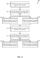
- FIG. 3 illustrates a method 300 of tracking wireless assets by using a switchable, oscillating near-field and far-field antenna.
- a far-field antenna is energized and used to transmit a scan signal into the area immediately surrounding the far-field antenna.
- this far-field antenna may be coupled to or otherwise associated with a transceiver of an access control reader, and the access control reader may further be installed at an access point.
- the scan signal propagates through the nearby area, with an effective range of approximately 30 feet from the point of transmission.
- the scan signal is received by one or more RFID tags that are within the effective range of the far-field antenna.
- each RFID Upon receiving the scan signal, each RFID then transmits a unique return signal containing identification information and any other data that may be stored on the RFID tag.
- passive RFID tags may be used, capturing energy from the received scan signal and using it to broadcast the return signal into the area immediately surrounding the RFID tag.
- the transceiver receives return signals from the one or more RFID tags that received the scan signal of step 302. Using at least the information contained in the return signal, the location of a wireless asset associated with a given RFID tag is determined. For example, the signal strength of the return signal can be analyzed to determine a distance between the given RFID tag and the transceiver, and this distance can then be translated into a location.
- a velocity or direction of a wireless asset associated with a given RFID tag is determined by analyzing a change in its location with respect to time.
- the velocity or direction calculation can be used to predict a future position or destination of the wireless asset associated with the given RFID tag.
- a near-field portion of the far-field antenna is energized, and transmits a near-field scan signal into the area immediately surrounding the near-field portion of the far-field antenna. Once transmitted, the near-field scan signal propagates through the nearby area, with an effective range of approximately 18-24 inches from the point of transmission.
- the near-field scan signal is received by one or more RFID tags that are within the effective range of the near field portion of the far-field antenna.
- each RFID Upon receiving the near-field scan signal, each RFID then transmits a unique return signal containing identification information and any other data that may be stored on the RFID tag.
- passive RFID tags may be used, capturing energy from the received near-field scan signal and using it to broadcast the return signal into the area immediately surrounding the RFID tag.
- the transceiver receives return signals from the one or more RFID tags that received the near-field scan signal of step 310.
- the location of a wireless asset associated with a given RFID tag is determined. For example, the signal strength of the return signal can be analyzed to determine a distance between the given RFID tag and the transceiver, and this distance can then be translated into a location.
- the determination of location may be binary in nature: the wireless asset associated with the given RFID tag is either contained within the effective range of the near-field scan signal, or the given RFID tag is located somewhere outside of the effective range of the near-field scan signal.
- a velocity or direction of a wireless asset associated with a given RFID tag is determined by analyzing a change in its location with respect to time.
- the velocity or direction calculation can be used to predict a future position or destination of the wireless asset associated with the given RFID tag.
- this step may be omitted, as such information can be of limited use due to the small effective range of the near-field scan signal.
- step 314 or 316 The above steps outline a single cycle of the switchable, oscillating near-field and far-field antenna of the present disclosure.
- the method may then return to step 302 and be repeated as desired.
- the method is performed between 20 and 200 times a second, for an oscillation frequency of 20-200 Hz.
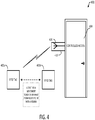
- FIG. 4 illustrates an example implementation of an access control system 400.
- an RFID tag 402 is associated with a wireless asset (not shown), such as a user or an object.
- An access control reader 410 is provided at a controlled access point 404, illustrated here as a lockable door. As described previously, access control reader 410 contains a transceiver with a switchable, oscillating near-field and far-field antenna 416.
- a wireless asset or user associated with RFID tag 402 seeks access to the controlled access point 404, and begins at a first position 402a, some distance remote from both controlled access point 404 and access control reader 410.
- this distance may be 25 feet, which is within the operating range of a far-field configuration of switchable antenna 416, but is not within the operating range of a near-field configuration of switchable antenna 416.
- RFID tag 402 will only be detected by the far-field configuration, becoming effectively invisible to antenna 416 while in the near-field configuration, as described previously. While in far-field configuration, access control system 410 may detect that RFID tag 402 is approximately 25 feet away, based on the received signal strength of a return signal received the RFID tag 402.
- access control system 410 may update a detected distance to RFID tag 402 accordingly. Additionally, access control system 410 may calculate or update a detected velocity of RFID tag 402. In some embodiments, the access control system 400 may predict that the wireless asset or user associated with RFID tag 402 plans to seek access to controller access point 404, and may run a pre-authorization in order to expedite the process. This pre-authorization process may be identical to a normal authorization process, or may simply involve initiating any communication channels or databases associated with the authorization process.
- the pre-authorization process may activate a camera (not shown) with a field of view covering controlled access point 404 and the surrounding area. This recording may be saved for a pre-determined amount of time, deleted if authorization is granted, or flagged and forwarded to security personnel if authorization is denied.
- the wireless asset or user associated with RFID tag 402 may then cross a threshold defining the operating range of the near-field configuration of switchable antenna 416, arriving at a second position 402b.
- RFID tag 402 may be detected by both the near-field configuration and the far-field configuration of switchable antenna 416. In some instances, RFID tag 402 may be detected by only the near-field configuration, due to the polarity issues that can affect far-field antennas, as described previously.
- the wireless asset or user associated with RFID tag 402 may pass through or otherwise access controlled access point 404, wherein the likelihood of any false, missing, or otherwise erroneous readings relating to RFID tag 402 is greatly reduced in comparison to any access control systems known in the art.
- FIG. 5A, and FIG. 5B illustrate exemplary possible system embodiments. The more appropriate embodiment will be apparent to those of ordinary skill in the art when practicing the present technology. Persons of ordinary skill in the art will also readily appreciate that other system embodiments are possible.
- FIG. 5A illustrates a conventional system bus computing system architecture 500 wherein the components of the system are in electrical communication with each other using a bus 505.
- Exemplary system 500 includes a processing unit (CPU, processor, microprocessor, or microcontroller (MCU))) 510 and a system bus 505 that couples various system components including the system memory 515, such as read only memory (ROM) 520 and random access memory (RAM) 525, to the processing unit 510.
- the system 500 can include a cache of high-speed memory connected directly with, in close proximity to, or integrated as part of the processing unit 510.
- the system 500 can copy data from the memory 515 and/or the storage device 530 to the cache 512 for quick access by the processing unit 510.
- the cache can provide a performance boost that avoids processing unit 510 delays while waiting for data.
- These and other modules can control or be configured to control the processing unit 510 to perform various actions.
- Other system memory 515 may be available for use as well.
- the memory 515 can include multiple different types of memory with different performance characteristics.
- the processing unit 510 can include any general purpose processor and a hardware module or software module, such as module 1 532, module 2 534, and module 3 536 stored in storage device 530, configured to control the processing unit 510 as well as a special-purpose processor where software instructions are incorporated into the actual processor design.
- the processing unit 510 may essentially be a completely self-contained computing system, containing multiple cores or processors, a bus, memory controller, cache, etc.
- a multi-core processor may be symmetric or asymmetric.
- an input device 545 can represent any number of input mechanisms, such as a microphone for speech, a touch-sensitive screen for gesture or graphical input, keyboard, mouse, motion input, speech and so forth.
- An output device 535 can also be one or more of a number of output mechanisms known to those of skill in the art.
- multimodal systems can enable a user to provide multiple types of input to communicate with the computing device 500.
- the communications interface 540 can generally govern and manage the user input and system output. There is no restriction on operating on any particular hardware arrangement and therefore the basic features here may easily be substituted for improved hardware or firmware arrangements as they are developed.
- Storage device 530 is a non-volatile memory and can be a hard disk or other types of computer readable media which can store data that are accessible by a computer, such as magnetic cassettes, flash memory cards, solid state memory devices, digital versatile disks, cartridges, random access memories (RAMs) 525, read only memory (ROM) 520, and hybrids thereof.
- RAMs random access memories
- ROM read only memory
- the storage device 530 can include software modules 532, 534, 536 for controlling the processing unit 510. Other hardware or software modules are contemplated.
- the storage device 530 can be connected to the system bus 505.
- a hardware module that performs a particular function can include the software component stored in a computer-readable medium in connection with the necessary hardware components, such as the processor 510, bus 505, display 535, and so forth, to carry out the function.
- FIG. 5B illustrates a computer system 550 having a chipset architecture that can be used in executing the described method and generating and displaying a graphical user interface (GUI).
- Computer system 550 is an example of computer hardware, software, and firmware that can be used to implement the disclosed technology.
- System 550 can include a processor 555, representative of any number of physically and/or logically distinct resources capable of executing software, firmware, and hardware configured to perform identified computations, such as a CPU, MCU (microcontroller), or microprocessor.
- Processor 555 can communicate with a chipset 560 that can control input to and output from processor 555.
- chipset 560 outputs information to output 565, such as a display, and can read and write information to storage device 570, which can include magnetic media, and solid state media, for example.
- Chipset 560 can also read data from and write data to RAM 575.
- a bridge 580 for interfacing with a variety of user interface components 585 can be provided for interfacing with chipset 560.
- Such user interface components 585 can include a keyboard, a microphone, touch detection and processing circuitry, a pointing device, such as a mouse, and so on.
- inputs to system 550 can come from any of a variety of sources, machine generated and/or human generated.
- Chipset 560 can also interface with one or more communication interfaces 590 that can have different physical interfaces.
- Such communication interfaces can include interfaces for wired and wireless local area networks, for broadband wireless networks, as well as personal area networks.
- Some applications of the methods for generating, displaying, and using the GUI disclosed herein can include receiving ordered datasets over the physical interface or be generated by the machine itself by processor 555 analyzing data stored in storage 570 or 575. Further, the machine can receive inputs from a user via user interface components 585 and execute appropriate functions, such as browsing functions by interpreting these inputs using processor 555.
- exemplary systems 500 and 550 can have more than one processor 510 or be part of a group or cluster of computing devices networked together to provide greater processing capability.
- the present technology may be presented as including individual functional blocks including functional blocks comprising devices, device components, steps or routines in a method embodied in software, or combinations of hardware and software.
- the computer-readable storage devices, mediums, and memories can include a cable or wireless signal containing a bit stream and the like.
- non-transitory computer-readable storage media expressly exclude media such as energy, carrier signals, electromagnetic waves, and signals per se.
- Such instructions can comprise, for example, instructions and data which cause or otherwise configure a general purpose computer, special purpose computer, or special purpose processing device to perform a certain function or group of functions. Portions of computer resources used can be accessible over a network.
- the computer executable instructions may be, for example, binaries, intermediate format instructions such as assembly language, firmware, or source code. Examples of computer-readable media that may be used to store instructions, information used, and/or information created during methods according to described examples include magnetic or optical disks, flash memory, USB devices provided with non-volatile memory, networked storage devices, and so on.
- Devices implementing methods according to these disclosures can comprise hardware, firmware and/or software, and can take any of a variety of form factors. Typical examples of such form factors include laptops, smart phones, small form factor personal computers, personal digital assistants, and so on. Functionality described herein also can be embodied in peripherals or add-in cards. Such functionality can also be implemented on a circuit board among different chips or different processes executing in a single device, by way of further example.
- the instructions, media for conveying such instructions, computing resources for executing them, and other structures for supporting such computing resources are means for providing the functions described in these disclosures.
Abstract


Description
- The present technology pertains to radio frequency (RF) antennas, and more specifically pertains to switchable near-field and far-field RF antennas.
- Radio frequency (RF) signals are often used in RFID systems in order to communicate with one or more tags, for purposes such as security or tracking. In general, an RFID system uses a transceiver to broadcast an interrogation signal, which is received by any operable RFID tag within the operable range of the transceiver. Upon receiving the interrogation signal, each RFID tag transmits a response signal that encodes unique tag identification information and other stored data. RFID tags can be classified as either passive or active, depending on how they are powered - passive RFID tags are powered via an onboard DC converter that extracts energy from the interrogation signal, and active RFID tags are powered by an onboard battery.
- In some applications, simply receiving a response signal is sufficient, as it indicates that the RFID tag (and any person or object associated with the tag) corresponding to the response signal is located within the boundaries defined by the range of the RFID transceiver. Greater granularity may be provided by transmitting each response signal at a known signal strength, given that signal strength decreases in a predictable manner. As such, the distance between the RFID transceiver and a source tag can be approximated by analyzing the signal strength of the response signal received at the transceiver.
- RFID systems may be divided into near-field systems and far-field systems, each exhibiting unique properties and requiring a specific type of antenna. The most immediately observable distinction between near-field and far-field is the separation range between tag and transceiver over which the RFID system remains operable. Near-field systems, often found in card readers and other close proximity applications, are constrained to a separation on the order of inches and are polarization agnostic. Far-field systems, often found in asset or product tracking applications, operate at a separation on the order of feet and are polarization sensitive (unable to obtain a reading), particularly at close range. As such, there is a need for a radio frequency system with a single antenna that is operable in both the near-field and the far-field, thereby providing an increased effective range of operation and eliminating the blind spots inherent to each individual mode of operation.
- Additional features and advantages of the disclosure will be set forth in the description which follows, and in part will be obvious from the description, or can be learned by practice of the herein disclosed principles. The features and advantages of the disclosure can be realized and obtained by means of the instruments and combinations particularly pointed out in the appended claims. These and other features of the disclosure will become more fully apparent from the following description and appended claims, or can be learned by the practice of the principles set forth herein.
- Disclosed is an access control system comprising: a controller and a transceiver coupled to the controller, wherein the transceiver comprises an antenna module including a near-field antenna and a far-field antenna, and wherein the near-field antenna is a subset of the far-field antenna.
- In one embodiment, the controller is configured to, using the transceiver, scan an RFID tag of a wireless asset and receive one or more return signals from the RFID tag, and determine a location of the wireless asset based on the one or more return signals.
- In one embodiment, the controller is configured to receive two or more return signals from the RFID tag and determine a direction of the wireless asset based on the two or more return signals.
- In one embodiment, the access control system further transmits position information corresponding with one or more of the location of the wireless asset and the direction of the wireless asset to a cloud controller, wherein the cloud controller is configured to receive position information from a plurality of networked asset control systems.
- In one embodiment, scanning the RFID tag further comprises oscillating the antenna module between a near-field scanning mode and a far-field scanning mode, wherein the near-field scanning mode corresponds with activation of the near-field antenna, and the far-field scanning mode corresponds with activation of the far-field antenna.
- In one embodiment, the return signal comprises signal strength and phase information associated with the RFID tag.
- In one embodiment, the near-field antenna is a UHF near-field loop antenna.
- Disclosed is a method for tracking a wireless asset, comprising scanning, using a transceiver, an RFID tag of a wireless asset, wherein the transceiver comprises an antenna module including a near-field antenna and a far-field antenna, receiving one or more return signals from the RFID tag, and determining a location of the wireless asset based on the one or more return signals.
- In one embodiment, the near-field antenna is a subset of the far-field antenna.
- In one embodiment, the method further comprises receiving two or more return signals from the RFID tag and determining a direction of the wireless asset based on the two or more return signals.
- In one embodiment, the method further comprises transmitting position information corresponding with one or more of the location of the wireless asset and a direction of the wireless asset to a cloud controller, wherein the cloud controller is configured to receive position information from a plurality of networked asset control systems.
- In one embodiment, scanning the RFID tag further comprises oscillating the antenna module between a near-field scanning mode and a far-field scanning mode, wherein the near-field scanning mode corresponds with activation of the near-field antenna, and wherein the far-field scanning mode corresponds with activation of the far-field antenna.
- In one embodiment, the return signal comprises signal strength and phase information associated with the RFID tag.
- Disclosed is a non-transitory computer-readable storage medium comprising instructions stored therein, which when executed by one or more processors, cause the processors to perform operations comprising scanning, using a transceiver, an RFID tag of a wireless asset, wherein the transceiver comprises an antenna module including a near-field antenna and a far-field antenna, receiving one or more return signals from the RFID tag, and determining a location of the wireless asset based on the one or more return signals.
- In one embodiment, the near-field antenna is a subset of the far-field antenna.
- In one embodiment, the processor is further configured to perform operations comprising receiving two or more return signals from the RFID tag and determining a direction of the wireless asset based on the two or more return signals.
- In one embodiment, the processor is further configured to perform operations comprising transmitting position information corresponding with one or more of the location of the wireless asset and a direction of the wireless asset to a cloud controller, wherein the cloud controller is configured to receive position information from a plurality of networked asset control systems.
- In one embodiment, scanning the RFID tag further comprises oscillating the antenna module between a near-field scanning mode and a far-field scanning mode, wherein the near-field scanning mode corresponds with activation of the near-field antenna, and wherein the far-field scanning mode corresponds with activation of the far-field antenna.
- In one embodiment, the return signal comprises signal strength and phase information associated with the RFID tag.
- In one embodiment, the near-field antenna is a UHF near-field loop antenna.
- In order to describe the manner in which the above-recited and other advantages and features of the disclosure can be obtained, a more particular description of the principles briefly described above will be rendered by reference to specific embodiments thereof which are illustrated in the appended drawings. Understanding that these drawings depict only exemplary embodiments of the disclosure and are not therefore to be considered to be limiting of its scope, the principles herein are described and explained with additional specificity and detail through the use of the accompanying drawings in which:
-
FIG. 1 illustrates an exemplary configuration of an environment in which an access control system of the present disclosure may operate. -
FIG. 2A illustrates a near-field antenna configuration of the switchable, oscillating antenna of the present disclosure. -
FIG. 2B illustrates a combined near-field and far-field antenna configuration of the switchable, oscillating antenna of the present disclosure. -
FIG. 2C illustrates a far-field antenna configuration of the switchable, oscillating antenna of the present disclosure. -
FIG. 3 illustrates a method of tracking wireless assets using the switchable, oscillating antenna of the present disclosure. -
FIG. 4 illustrates an exemplary access control system of the present disclosure. -
FIG. 5A illustrates a conventional system bus computing system architecture that can be used in implementing a system of the present disclosure. -
FIG. 5B illustrates a computer system having a chipset architecture that can be used in executing a method of the present disclosure. - Various embodiments of the disclosure are discussed in detail below. While specific implementations are discussed, it should be understood that these implementations are provided for illustrative purposes only. A person skilled in the relevant art will recognize that other components and configurations may be used without departing from the spirit and scope of the disclosure.
- The disclosed access control system and method are best understood in the context of the larger environment in which they operate. Accordingly,
FIG. 1 depicts an illustrative schematic diagram of anaccess control system 100 and its constituent components. Broadly, the access control system may be broken down into three constituent components: acloud controller 102, some number n ofaccess control readers 110a-110n, and a plurality of wireless assets 120 (illustrated here as RFID tags, although it is understood that a variety of other radio-frequency (RF) devices or wireless identification tags may be used). Althoughaccess control system 100 is not illustrated with respect to any specific implementation, by means of example, such an access control system may be used for purposes such as asset tracking in a factory, warehouse, or other commercial building, wherein integrated or externally attached RFID tags are used to track the flow of packages or other goods, or for a building security system, wherein RFID tags are embedded into identification cards and used to verify and grant individual access to locked doors or other secured assets. - Returning to
FIG. 1 , and turning first tocloud controller 102, a number of different configurations may be employed. As illustrated,cloud controller 102 is communicatively coupled with each of theaccess control readers 110a-110n via a direct link, although in some embodiments,cloud controller 102 may be communicatively coupled with one or more of theaccess control readers 110a-110n via an indirect link, wherein one or more intermediate nodes or access control readers are communicatively coupled betweencloud controller 102 and the destination access control reader. As used herein, communicatively coupled is understood to mean any data transmission link between two or more computing devices or components, wired or wireless. Examples of such data transmission links include, but are not limited to, a Local Area Network (LAN), a Wide Area Network (WAN), Intranet, Internet, or any other wired or wireless networking and data transmission technologies that are known in the art. - In some embodiments,
cloud controller 102 and theaccess control readers 110a-110n may be provided separately, in order to provide increased security and reliability. For example,cloud controller 102 may be located on a separate network from that of theaccess control readers 110a-110n, such that both networks much be breached or otherwise compromised in order foraccess control system 100 to be defeated. In some embodiments,cloud controller 102 may be physically remote fromaccess control readers 110a-110n, which can increase security and provide greater operational flexibility by allowing theaccess control system 100 to be operated and monitored constantly, for example through a secure web portal or web application. - In general operation,
cloud controller 102 is provided in a tiered hierarchy, such that it is above each of theaccess control readers 110a-110n. In some embodiments,cloud controller 102 and theaccess control readers 110a-110n can exist in a master-slave relationship, whereincloud controller 102 oversees all aspects of operation for each of the access control readers. However,cloud controller 102 is not limited to such a master-slave relationship, and it is understood that the access control readers may be capable of a partial or total degree of autonomy in their operation (provided, for example, viacontroller 112 contained withinaccess control reader 110a), such thatcloud controller 102 only assumes a supervisory role, such as monitoring for any abnormal events or other deviations from expected operation. -
Cloud controller 102 may be provided on a single computing device, such as a computer server, orcloud controller 102 may be provided across a plurality of different computing devices that comprise, for example, a cloud computing cluster. As further example,cloud controller 102 may be implemented as a central processing unit (CPU), a microcontroller (MCU), a microprocessor, integrated circuitry, or any other controller known in the art. In some embodiments,cloud controller 102 may be connected to a database (not shown) that can store historical records of each interaction between the plurality ofRFID tags 120 and theaccess control readers 110a-110n. The database may also be used to store one or more access control policies, with a specific access control policy being manually selectable (and editable) by an administrator ofaccess control system 100, or being automatically selectable according to one or more pre-defined rules, based on criteria such as time or location. - Turning next to access
control readers 110a-110n, it is understood thataccess control system 100 contains some number n of access control readers, that may be physically identically or otherwise capable of providing substantially similar functionality. Each access control reader may be associated with a certain access point, and any given access point may be associated with one or more access control readers. As depicted inFIG. 1 , each of theaccess control readers 110a-110n is illustrated in an identical schematic form, and the following description will be made with reference to accesscontrol reader 110a, but is extensible to each of theaccess control readers 110a-110n. -
Access control reader 110a consists of three primary components: acontroller 112, atransceiver 114, and a far-field antenna 116. A near-field antenna 118 is formed from a subset of far-field antenna 116, as will be subsequently explained in greater depth.Controller 112 may be provided by a processing element, capable of implementing programmed commands that may be edited or modified by an administrator ofaccess control system 100. In some embodiments,controller 112 may simply receive one or more control commands fromcloud controller 102 and execute them accordingly. - As illustrated,
transceiver 114 is coupled tocontroller 112, and is capable of transmitting and receiving RF or other electromagnetic (EM) signals, as is understood by one of ordinary skill in the art. The signal processing required to support this transmitting and receiving functionality may be performed by a processing element ofcontroller 112 or a processing element ofcloud controller 102 In some embodiments,transceiver 114 may contain its own signal processing element, particularly in a large access control system where it may be impractical to perform signal processing atcontroller 112 orcloud controller 102. -
Transceiver 114 is further coupled to far-field antenna 116, which is used to interact with one or more of the plurality of RFID tags. In some embodiments, far-field antenna 116 has an operable range of up to 30 feet, although it is understood that the operable range of far-field antenna 116 may depend upon a number of different factors such as the operating wavelength ofaccess control system 100, the physical geometry of the access point at which far-field antenna 116 is located, the polarization ofaccess control reader 110a and the polarization of a given RFID tag. - Near-
field antenna 118 is formed from a subset of far-field antenna 116, which may be achieved by selectively energizing a certain portion of far-field antenna 116, as will be explained with respect toFIG. 2 . This selective energization may be controlled bycontroller 112,cloud controller 102, or some combination of the two. When near-field antenna 118 is energized, it may have an operational range of approximately 18 inches, although once again, it is understood that this operable range may depend upon a number of different factors as would be appreciated by one of ordinary skill in the art. Each of far-field antenna 116 and near-field antenna 118 may interact with one or more of the plurality ofRFID tags 120 in order to perform a read operation, and multiple RFID tags may be read simultaneously. In one aspect of the disclosure,access control reader 110a may oscillate between energizing far-field antenna 116 and energizing near-field antenna 118, in order to provide an improved and more reliable tracking of the plurality of RFID tags 120. - Turning now to
FIG. 2A-2C , three different antenna configurations are illustrated, wherein each of the distinct antenna configurations can be achieved using the same set of physical antenna components, as indicated by the numerical labeling common to the three figures. For clarity of explanation, each configuration is presented in a simplified diagrammatic form, wherein a solid line indicates an energized antenna portion and a dashed line indicates a non-energized antenna portion. -
FIG. 2A depicts a near-field antenna configuration 200a, wherein only a near-field loop antenna is energized.FIG. 2B depicts a combined near-field and far-field antenna configuration 200b, in which a near-field loop antenna and a far-field antenna are energized.FIG. 2C depicts a far-field antenna configuration 200c, wherein only a far-field loop antenna is energized. - In a first embodiment,
access control reader 110a may oscillate between near-field antenna configuration 200a and combined near-field and far-field antenna configuration 200b. In a second embodiment,access control reader 110a may oscillate between near-field antenna configuration 200a and far-field antenna configuration 200c. The oscillation may take place on the order of 20-200 Hz, wherein a greater oscillation frequency can provide a greater resolution with respect to the movement and position of a given RFID tag in the vicinity ofaccess control reader 110a, although it is understood that other oscillation frequencies may be implemented as needed or as desired for a given application. - This oscillation is governed by an
oscillation controller 208, which is coupled toswitches Switches Oscillation controller 208 may be provided bycontroller 112 or bycloud controller 102, as explained previously.Oscillation controller 208 may also be a standalone component, equipped to receive control or timing commands from one or more ofcontroller 112 andcloud controller 102. - In near-
field antenna configuration 200a, switches 206a and 206b are positioned such that only a near-field loop antenna 210 is energized, wherein near-field loop antenna 210 is formed from a series connection betweenfirst loop portion 202a, abridge portion 205, and asecond loop portion 202b. AlthoughFIG. 2A depicts only a single near-field loop antenna 210, some embodiments may make use of one or more near-field loop antennas. In some embodiments, the one or more near-field loop antennas may be provided as Ultra High Frequency (UHF) antennas. As illustrated, the distal ends offirst loop portion 202a andsecond loop portion 202b are left unconnected, but in operation, may be connected to a matching or tuning network, as would be understood by one of ordinary skill in the art. - In such a configuration,
first loop portion 202a is connected as a feed andsecond loop portion 202b is connected as a ground (or vice versa). When near-field loop antenna 210 is energized, an RF signal is sent to the feed loop portion. Based on the length and tuning of near-field loop antenna 210, this RF signal is matched such that there is an even current distributed across the loop and then grounded, causing an RF field to be generated. This RF field radiates perpendicular to the center of the loop, to a height that is proportional to the diameter of the loop, thereby defining a three-dimensional read-zone in which near-field loop antenna 210 is able to read an RFID tag. As mentioned previously, this read-zone may extend approximately 18-24 inches away from one or more of the center of near-field loop antenna 210 or theplane containing antenna 210, but in general is limited to four inches away in the absence of a high-powered near-field antenna. The specific geometry of this RF field or read-zone can be further adjusted by varying the shape and polarity ofantenna 210; by varying the current and manner in which it is driven through the loop; and through a variety of other factors as would be appreciated by one of ordinary skill in the art. - On the basis of this 18-24 inch read-zone, near-
field loop antenna 210 is more ideally situated for applications such as door locks or other applications that will predictably involve contact or close proximity between access control reader 210a and an RFID tag. In such applications, a read signal received at access control reader 210a can generally be taken to indicate that a given RFID tag (and the individual or object associated with it) is located at an access point controlled by access control reader 210a and is further seeking to enter the access point. - As such, near-
field loop antenna 210 is useful for performing the actual validating step for granting or denying access to an access point, but due to its limited range and small read-zone, is ultimately ineffective for tracking the movement of assets such as individuals or objects. In general, an access control reader that only makes use of a near-field antenna can only track actual attempts to access the access point. In other words, a near-field access control reader can only log the RFID tags that were placed within the read-zone and either granted or denied access. A near-field only access control reader may fail to log any tags and associated assets that are exiting the access point, unless an additional access control reader is installed, creating additional expense and further slowing the rate at which assets may enter and exit the access point. - Combined near-field and far-
field antenna configuration 200b addresses this issue. In this configuration, as seen inFIG. 2B ,controller 208 adjustsswitches field antenna configuration 200a) a first far-field portion 204a and a second far-field portion 204b, thereby forming a combined near-field and far-field antenna 220. - Combined
antenna 220 has a far greater operational range than near-field loop antenna 210, capable of reading RFID tags at a range of approximately 30 feet. By virtue of this increased operational range, combinedantenna 220 can be used to track RFID tags and their associated assets based on analyzing the signal strength of the return signal transmitted by a given RFID tag, where a given signal strength can be mapped to or otherwise correlated with a specific distance from the combinedantenna 220. However, a single reading is often not helpful when taken in isolation, due to inherent challenges in far-field readings. For example, a return signal may experience unaccounted for attenuation if it passes through any medium other than air while traveling on a path between an originating RFID tag and a receiving antenna or access control point. In some instances, a return signal may experience multiple reflections before being received at an antenna or access control point. In both of these cases, the signal strength of the received return signal will be lower than what would otherwise be expected at the given distance between the originating RFID tag and receiving antenna or access control point, leading to an over-estimation of distance. In some embodiments, phase information associated with the return signal transmitted by the given RFID tag may be analyzed, either alone or in combination with the signal strength, as the phase information may be less affected by any attenuation effects in comparison to the signal strength. - Therefore, it can be more useful to take multiple readings of an RFID tag and calculate an average distance rather than an instantaneous distance, wherein the average distance and a true distance may converge at a higher sample rate (i.e. the oscillation frequency or the read frequency of the access control reader). In some embodiments, each reading of a given RFID tag can be saved at one or more of the access control reader and
cloud controller 102, and likewise, the average distance calculation can be performed at one or more of the access control reader andcloud controller 102. - These saved readings can enable a number of additional calculations to be performed. For example, if an RFID tag is simultaneously in range of more than one of the
access control readers 110a-110n, then an approximate triangulation of the position of the RFID tag and associated asset may be performed, based on known coordinates of theaccess control readers 110a-100n. In such an embodiment, the triangulation calculation is performed atcloud controller 102, as it requires the simultaneous collection and coordination of information from multiple access control readers. - A velocity or direction of the RFID tag and associated asset may also be calculated or approximated by analyzing a change in position or distance with respect to time. Such information can be useful, for example, in determining whether an RFID tag and its associated asset are approaching or moving away from an access point and access control reader. This determination may also be simultaneously made for one or more RFID tags and their associated assets, which can improve security by tracking and accounting for all assets entering or exiting the access point, rather than only tracking and accounting for the asset that presented an RFID tag for verification and authorization at the access control reader. For example, access control readers operable in only the near-field are vulnerable to what is commonly referred to as a "walk behind", wherein an authorized user may present an RFID tag to gain entrance to an access point such as a building and then allow other users, whether authorized or unauthorized, to enter at the same time.
- In some embodiments,
cloud controller 102 may be adapted to predict the movement or flow of assets on the basis of this position and velocity or direction data, which can prove critically important for scenarios such as alerting security personnel to a predicted attempt to enter a geo-fenced or otherwise restricted zone within an access control system. In some cases, this predictive data may be used to avoid or reduce bottlenecks in the flow of assets, whether humans or objects, which are passing through an access point, by either re-routing assets or providing increased throughput at the access point. - While the issue of reliability at medium to long-range is solved by taking an average of multiple samples, far-field antennas remain unreliable at short-range due to fundamental challenges presented by the polarities of the RFID tag and a far-field antenna. If a far-field antenna is provided in a fixed or static configuration within an access control reader, then so too is the polarity of the far-field antenna fixed or static (although some embodiments may provide for a variable far-field antenna polarity, at additional expense and complexity). For example, a far-field antenna may be provided with a fixed horizontal polarization. Such a horizontally polarized far-field antenna can generally read a horizontally polarized RFID tag at close range, including the 4-24 inch read-zone provided by the previously discussed near-
field antenna 210. - However, a horizontally polarized far-field antenna cannot reliably or predictably read a vertically polarized RFID tag at close range, and will often fail to obtain any reading whatsoever when such a polarization offset exists between the RFID tag and far-field antenna. In many applications, such a failure to obtain a reading is unacceptable, and consequently, security-oriented access control readers rely solely upon near-field antennas, choosing a limited, but reliable, feature set over the enhanced, but sometimes unreliable, tracking features enabled by far-field antennas.
- The presently disclosed access control system obviates any such issue or decision by providing a near-
field antenna 210 that is a subset of a larger far-field antenna and oscillating between the two - thereby coupling the enhanced tracking and prediction of the far-field antenna with the high reliability of the near-field antenna. At 200 Hz, an access control system of the present disclosure can perform 100 near-field reads every second, using near-field antenna configuration field antenna configuration 200b or far-field antenna configuration 200c. In some embodiments, the access control system may use other read frequencies, or other read patterns. For example, the access control system may perform a read pattern of five consecutive far-field reads and then one near-field read, wherein the read pattern is not limited to any specific read frequency. Such a read pattern may be desirable in environments with a large number of assets to be tracked in the far-field, particularly when viewed in comparison to the number of assets to be tracked in the near-field. - Far-
field antenna configuration 200c, as seen inFIG. 2C , is largely identical to combined near-field and far-field antenna configuration 200b, with the difference beingbridge portion 205, which is not energized in far-field antenna configuration 200c. Far-field antenna configuration 200c can provide the exact same functionality as that of the combined near-field and far-field antenna configuration 200b, described above, for example, achieving an operating range of approximately 30 feet. However, by virtue of thede-energized bridge portion 205, far-field antenna configuration 200c suffers from more pronounced difficulties and unreliability when reading RFID tags at short-range. While these reliability issues are still obviated by oscillating between near-field antenna configuration 200a and far-field antenna configuration 200c, it may sometimes be desirable to use combined near-field and far-field antenna configuration 200b in implementations where cost or engineering complexity are of a lesser concern. -
FIG. 3 illustrates amethod 300 of tracking wireless assets by using a switchable, oscillating near-field and far-field antenna. Starting at astep 302, a far-field antenna is energized and used to transmit a scan signal into the area immediately surrounding the far-field antenna. As previously discussed, this far-field antenna may be coupled to or otherwise associated with a transceiver of an access control reader, and the access control reader may further be installed at an access point. Once transmitted, the scan signal propagates through the nearby area, with an effective range of approximately 30 feet from the point of transmission. - In a
step 304, the scan signal is received by one or more RFID tags that are within the effective range of the far-field antenna. Upon receiving the scan signal, each RFID then transmits a unique return signal containing identification information and any other data that may be stored on the RFID tag. In some embodiments, passive RFID tags may be used, capturing energy from the received scan signal and using it to broadcast the return signal into the area immediately surrounding the RFID tag. - In a
step 306, the transceiver receives return signals from the one or more RFID tags that received the scan signal ofstep 302. Using at least the information contained in the return signal, the location of a wireless asset associated with a given RFID tag is determined. For example, the signal strength of the return signal can be analyzed to determine a distance between the given RFID tag and the transceiver, and this distance can then be translated into a location. - In a
step 308, which can be performed concurrent with or subsequent to step 306, a velocity or direction of a wireless asset associated with a given RFID tag is determined by analyzing a change in its location with respect to time. In some embodiments, the velocity or direction calculation can be used to predict a future position or destination of the wireless asset associated with the given RFID tag. - In a
step 310, a near-field portion of the far-field antenna is energized, and transmits a near-field scan signal into the area immediately surrounding the near-field portion of the far-field antenna. Once transmitted, the near-field scan signal propagates through the nearby area, with an effective range of approximately 18-24 inches from the point of transmission. - In a
step 312, the near-field scan signal is received by one or more RFID tags that are within the effective range of the near field portion of the far-field antenna. Upon receiving the near-field scan signal, each RFID then transmits a unique return signal containing identification information and any other data that may be stored on the RFID tag. In some embodiments, passive RFID tags may be used, capturing energy from the received near-field scan signal and using it to broadcast the return signal into the area immediately surrounding the RFID tag. - In a
step 314, the transceiver receives return signals from the one or more RFID tags that received the near-field scan signal ofstep 310. Using at least the information contained in the return signal, the location of a wireless asset associated with a given RFID tag is determined. For example, the signal strength of the return signal can be analyzed to determine a distance between the given RFID tag and the transceiver, and this distance can then be translated into a location. In some embodiments, the determination of location may be binary in nature: the wireless asset associated with the given RFID tag is either contained within the effective range of the near-field scan signal, or the given RFID tag is located somewhere outside of the effective range of the near-field scan signal. - In a
step 316, which can be performed concurrent with or subsequent to step 306, a velocity or direction of a wireless asset associated with a given RFID tag is determined by analyzing a change in its location with respect to time. In some embodiments, the velocity or direction calculation can be used to predict a future position or destination of the wireless asset associated with the given RFID tag. In some embodiments, this step may be omitted, as such information can be of limited use due to the small effective range of the near-field scan signal. - The above steps outline a single cycle of the switchable, oscillating near-field and far-field antenna of the present disclosure. Upon the completion of a cycle (at either step 314 or 316), the method may then return to step 302 and be repeated as desired. In some embodiments, the method is performed between 20 and 200 times a second, for an oscillation frequency of 20-200 Hz.
-
FIG. 4 illustrates an example implementation of anaccess control system 400. In this example, an RFID tag 402 is associated with a wireless asset (not shown), such as a user or an object. Anaccess control reader 410 is provided at a controlledaccess point 404, illustrated here as a lockable door. As described previously,access control reader 410 contains a transceiver with a switchable, oscillating near-field and far-field antenna 416. - In the illustrated example, a wireless asset or user associated with RFID tag 402 seeks access to the controlled
access point 404, and begins at afirst position 402a, some distance remote from both controlledaccess point 404 andaccess control reader 410. For example, this distance may be 25 feet, which is within the operating range of a far-field configuration ofswitchable antenna 416, but is not within the operating range of a near-field configuration ofswitchable antenna 416. - Consequently, as
antenna 416 oscillates between a near-field configuration and a far-field configuration, RFID tag 402 will only be detected by the far-field configuration, becoming effectively invisible toantenna 416 while in the near-field configuration, as described previously. While in far-field configuration,access control system 410 may detect that RFID tag 402 is approximately 25 feet away, based on the received signal strength of a return signal received the RFID tag 402. - As the wireless asset or user associated with RFID tag 402 continues to approach controlled
access point 404, it will continue to be detected only by the far-field configuration ofswitchable antenna 416, whereinaccess control system 410 may update a detected distance to RFID tag 402 accordingly. Additionally,access control system 410 may calculate or update a detected velocity of RFID tag 402. In some embodiments, theaccess control system 400 may predict that the wireless asset or user associated with RFID tag 402 plans to seek access tocontroller access point 404, and may run a pre-authorization in order to expedite the process. This pre-authorization process may be identical to a normal authorization process, or may simply involve initiating any communication channels or databases associated with the authorization process. In some embodiments, the pre-authorization process may activate a camera (not shown) with a field of view covering controlledaccess point 404 and the surrounding area. This recording may be saved for a pre-determined amount of time, deleted if authorization is granted, or flagged and forwarded to security personnel if authorization is denied. - The wireless asset or user associated with RFID tag 402 may then cross a threshold defining the operating range of the near-field configuration of
switchable antenna 416, arriving at asecond position 402b. At this point, RFID tag 402 may be detected by both the near-field configuration and the far-field configuration ofswitchable antenna 416. In some instances, RFID tag 402 may be detected by only the near-field configuration, due to the polarity issues that can affect far-field antennas, as described previously. - Once RFID tag 402 is detected by the near-field configuration of
switchable antenna 416, and authorization is granted, the wireless asset or user associated with RFID tag 402 may pass through or otherwise access controlledaccess point 404, wherein the likelihood of any false, missing, or otherwise erroneous readings relating to RFID tag 402 is greatly reduced in comparison to any access control systems known in the art. -
FIG. 5A, and FIG. 5B illustrate exemplary possible system embodiments. The more appropriate embodiment will be apparent to those of ordinary skill in the art when practicing the present technology. Persons of ordinary skill in the art will also readily appreciate that other system embodiments are possible. -
FIG. 5A illustrates a conventional system buscomputing system architecture 500 wherein the components of the system are in electrical communication with each other using abus 505.Exemplary system 500 includes a processing unit (CPU, processor, microprocessor, or microcontroller (MCU))) 510 and asystem bus 505 that couples various system components including thesystem memory 515, such as read only memory (ROM) 520 and random access memory (RAM) 525, to theprocessing unit 510. Thesystem 500 can include a cache of high-speed memory connected directly with, in close proximity to, or integrated as part of theprocessing unit 510. Thesystem 500 can copy data from thememory 515 and/or thestorage device 530 to thecache 512 for quick access by theprocessing unit 510. In this way, the cache can provide a performance boost that avoids processingunit 510 delays while waiting for data. These and other modules can control or be configured to control theprocessing unit 510 to perform various actions.Other system memory 515 may be available for use as well. Thememory 515 can include multiple different types of memory with different performance characteristics. Theprocessing unit 510 can include any general purpose processor and a hardware module or software module, such asmodule 1 532,module 2 534, andmodule 3 536 stored instorage device 530, configured to control theprocessing unit 510 as well as a special-purpose processor where software instructions are incorporated into the actual processor design. Theprocessing unit 510 may essentially be a completely self-contained computing system, containing multiple cores or processors, a bus, memory controller, cache, etc. A multi-core processor may be symmetric or asymmetric. - To enable user interaction with the
computing device 500, aninput device 545 can represent any number of input mechanisms, such as a microphone for speech, a touch-sensitive screen for gesture or graphical input, keyboard, mouse, motion input, speech and so forth. Anoutput device 535 can also be one or more of a number of output mechanisms known to those of skill in the art. In some instances, multimodal systems can enable a user to provide multiple types of input to communicate with thecomputing device 500. Thecommunications interface 540 can generally govern and manage the user input and system output. There is no restriction on operating on any particular hardware arrangement and therefore the basic features here may easily be substituted for improved hardware or firmware arrangements as they are developed. -
Storage device 530 is a non-volatile memory and can be a hard disk or other types of computer readable media which can store data that are accessible by a computer, such as magnetic cassettes, flash memory cards, solid state memory devices, digital versatile disks, cartridges, random access memories (RAMs) 525, read only memory (ROM) 520, and hybrids thereof. - The
storage device 530 can includesoftware modules processing unit 510. Other hardware or software modules are contemplated. Thestorage device 530 can be connected to thesystem bus 505. In one aspect, a hardware module that performs a particular function can include the software component stored in a computer-readable medium in connection with the necessary hardware components, such as theprocessor 510,bus 505,display 535, and so forth, to carry out the function. -
FIG. 5B illustrates acomputer system 550 having a chipset architecture that can be used in executing the described method and generating and displaying a graphical user interface (GUI).Computer system 550 is an example of computer hardware, software, and firmware that can be used to implement the disclosed technology.System 550 can include aprocessor 555, representative of any number of physically and/or logically distinct resources capable of executing software, firmware, and hardware configured to perform identified computations, such as a CPU, MCU (microcontroller), or microprocessor.Processor 555 can communicate with achipset 560 that can control input to and output fromprocessor 555. In this example,chipset 560 outputs information tooutput 565, such as a display, and can read and write information tostorage device 570, which can include magnetic media, and solid state media, for example.Chipset 560 can also read data from and write data to RAM 575. Abridge 580 for interfacing with a variety ofuser interface components 585 can be provided for interfacing withchipset 560. Suchuser interface components 585 can include a keyboard, a microphone, touch detection and processing circuitry, a pointing device, such as a mouse, and so on. In general, inputs tosystem 550 can come from any of a variety of sources, machine generated and/or human generated. -
Chipset 560 can also interface with one ormore communication interfaces 590 that can have different physical interfaces. Such communication interfaces can include interfaces for wired and wireless local area networks, for broadband wireless networks, as well as personal area networks. Some applications of the methods for generating, displaying, and using the GUI disclosed herein can include receiving ordered datasets over the physical interface or be generated by the machine itself byprocessor 555 analyzing data stored instorage user interface components 585 and execute appropriate functions, such as browsing functions by interpreting theseinputs using processor 555. - It can be appreciated that
exemplary systems processor 510 or be part of a group or cluster of computing devices networked together to provide greater processing capability. - For clarity of explanation, in some instances the present technology may be presented as including individual functional blocks including functional blocks comprising devices, device components, steps or routines in a method embodied in software, or combinations of hardware and software.
- In some embodiments the computer-readable storage devices, mediums, and memories can include a cable or wireless signal containing a bit stream and the like. However, when mentioned, non-transitory computer-readable storage media expressly exclude media such as energy, carrier signals, electromagnetic waves, and signals per se.
- Methods according to the above-described examples can be implemented using computer-executable instructions that are stored or otherwise available from computer readable media. Such instructions can comprise, for example, instructions and data which cause or otherwise configure a general purpose computer, special purpose computer, or special purpose processing device to perform a certain function or group of functions. Portions of computer resources used can be accessible over a network. The computer executable instructions may be, for example, binaries, intermediate format instructions such as assembly language, firmware, or source code. Examples of computer-readable media that may be used to store instructions, information used, and/or information created during methods according to described examples include magnetic or optical disks, flash memory, USB devices provided with non-volatile memory, networked storage devices, and so on.
- Devices implementing methods according to these disclosures can comprise hardware, firmware and/or software, and can take any of a variety of form factors. Typical examples of such form factors include laptops, smart phones, small form factor personal computers, personal digital assistants, and so on. Functionality described herein also can be embodied in peripherals or add-in cards. Such functionality can also be implemented on a circuit board among different chips or different processes executing in a single device, by way of further example.
- The instructions, media for conveying such instructions, computing resources for executing them, and other structures for supporting such computing resources are means for providing the functions described in these disclosures.
- Although a variety of examples and other information was used to explain aspects within the scope of the appended claims, no limitation of the claims should be implied based on particular features or arrangements in such examples, as one of ordinary skill would be able to use these examples to derive a wide variety of implementations. Further and although some subject matter may have been described in language specific to examples of structural features and/or method steps, it is to be understood that the subject matter defined in the appended claims is not necessarily limited to these described features or acts. For example, such functionality can be distributed differently or performed in components other than those identified herein. Rather, the described features and steps are disclosed as examples of components of systems and methods within the scope of the appended claims.
Claims (15)
- An access control system comprising:a controller; anda transceiver coupled to the controller, wherein the transceiver comprises an antenna module including a near-field antenna and a far-field antenna, and wherein the near-field antenna is a subset of the far-field antenna.
- The access control system of claim 1, wherein the controller is configured to perform operations comprising:scanning, using the transceiver, one or more RFID tags, wherein each RFID tag is associated with a corresponding wireless asset;receiving, via the transceiver, a one or more return signals from each of the RFID tags; anddetermining a location of each wireless asset based on the one or more return signals received from each RFID tag associated with the wireless asset.
- The access control system of claim 2, wherein the controller is configured to perform operations comprising:receiving two or more return signals from the RFID tag; anddetermining a direction of the wireless asset based on the two or more return signals.
- The access control system of claim 2 or 3, further comprising:transmitting position information corresponding with one or more of the location of the wireless asset and the direction of the wireless asset to a cloud controller, wherein the cloud controller is configured to receive position information from a plurality of networked asset control systems.
- The access control system of claim 2, 3, or 4, wherein scanning the RFID tag further comprises:oscillating the antenna module between a near-field scanning mode and a far-field scanning mode,wherein the near-field scanning mode corresponds with activation of the near-field antenna, andwherein the far-field scanning mode corresponds with activation of the far-field antenna.
- The access control system of any of claims 2 to 5, wherein the return signal comprises signal strength and phase information associated with the RFID tag.
- The access control system of any preceding claim, wherein the near-field antenna is a UHF near-field loop antenna.
- A method for tracking a wireless asset, comprising:scanning, using a transceiver, an RFID tag of a wireless asset, wherein the transceiver comprises an antenna module including a near-field antenna and a far-field antenna;receiving a one or more return signals from the RFID tag; anddetermining a location of the wireless asset based on the one or more return signals.
- The method of claim 8, wherein the near-field antenna is a subset of the far-field antenna.
- The method of claim 8 or 9, further comprising:receiving two or more return signals from the RFID tag; anddetermining a direction of the wireless asset based on the two or more return signals.
- The method of claim 8, 9, or 10, further comprising:transmitting position information corresponding with one or more of the location of the wireless asset and a direction of the wireless asset to a cloud controller, wherein the cloud controller is configured to receive position information from a plurality of networked asset control systems.
- The method of any of claims 8 to 11, wherein scanning the RFID tag further comprises:oscillating the antenna module between a near-field scanning mode and a far-field scanning mode,wherein the near-field scanning mode corresponds with activation of the near-field antenna, andwherein the far-field scanning mode corresponds with activation of the far-field antenna.
- The method of any of claims 8 to 12, wherein the return signal comprises signal strength and phase information associated with the RFID tag.
- The method of any of claims 8 to 13, wherein the near-field antenna is a UHF near-field loop antenna.
- A non-transitory computer-readable storage medium comprising instructions stored therein, which when executed by one or more processors, cause the processors to perform the method of any of claims 8 to 14.
Applications Claiming Priority (1)
| Application Number | Priority Date | Filing Date | Title |
|---|---|---|---|
| US15/258,940 US10326204B2 (en) | 2016-09-07 | 2016-09-07 | Switchable, oscillating near-field and far-field antenna |
Publications (3)
| Publication Number | Publication Date |
|---|---|
| EP3293679A2 true EP3293679A2 (en) | 2018-03-14 |
| EP3293679A3 EP3293679A3 (en) | 2018-08-08 |
| EP3293679B1 EP3293679B1 (en) | 2021-12-22 |
Family
ID=59501261
Family Applications (1)
| Application Number | Title | Priority Date | Filing Date |
|---|---|---|---|
| EP17183681.0A Active EP3293679B1 (en) | 2016-09-07 | 2017-07-28 | Switchable, oscillating near-field and far-field antenna |
Country Status (2)
| Country | Link |
|---|---|
| US (1) | US10326204B2 (en) |
| EP (1) | EP3293679B1 (en) |
Families Citing this family (28)
| Publication number | Priority date | Publication date | Assignee | Title |
|---|---|---|---|---|
| US9967906B2 (en) | 2015-01-07 | 2018-05-08 | Cisco Technology, Inc. | Wireless roaming using a distributed store |
| US9985837B2 (en) | 2015-07-23 | 2018-05-29 | Cisco Technology, Inc. | Refresh of the binding tables between data-link-layer and network-layer addresses on mobility in a data center environment |
| US11151856B2 (en) * | 2016-11-29 | 2021-10-19 | Jerry M. Miniard | Distributed security system using position tracking |
| US10440723B2 (en) | 2017-05-17 | 2019-10-08 | Cisco Technology, Inc. | Hierarchical channel assignment in wireless networks |
| US10555341B2 (en) | 2017-07-11 | 2020-02-04 | Cisco Technology, Inc. | Wireless contention reduction |
| US10440031B2 (en) | 2017-07-21 | 2019-10-08 | Cisco Technology, Inc. | Wireless network steering |
| US10735981B2 (en) | 2017-10-10 | 2020-08-04 | Cisco Technology, Inc. | System and method for providing a layer 2 fast re-switch for a wireless controller |
| WO2019090106A1 (en) * | 2017-11-03 | 2019-05-09 | Sensormatic Electronics, LLC | Methods and system for employee monitoring and business rule and quorum compliance monitoring |
| US10375667B2 (en) | 2017-12-07 | 2019-08-06 | Cisco Technology, Inc. | Enhancing indoor positioning using RF multilateration and optical sensing |
| US10505718B1 (en) | 2018-06-08 | 2019-12-10 | Cisco Technology, Inc. | Systems, devices, and techniques for registering user equipment (UE) in wireless networks using a native blockchain platform |
| US10673618B2 (en) | 2018-06-08 | 2020-06-02 | Cisco Technology, Inc. | Provisioning network resources in a wireless network using a native blockchain platform |
| US10873636B2 (en) | 2018-07-09 | 2020-12-22 | Cisco Technology, Inc. | Session management in a forwarding plane |
| CN109191619B (en) * | 2018-07-13 | 2021-01-26 | 上海建工集团股份有限公司 | RFID-based construction site informatization access control system and setting and using method thereof |
| US10671462B2 (en) | 2018-07-24 | 2020-06-02 | Cisco Technology, Inc. | System and method for message management across a network |
| US11252040B2 (en) | 2018-07-31 | 2022-02-15 | Cisco Technology, Inc. | Advanced network tracing in the data plane |
| US10735209B2 (en) | 2018-08-08 | 2020-08-04 | Cisco Technology, Inc. | Bitrate utilization feedback and control in 5G-NSA networks |
| US10284429B1 (en) | 2018-08-08 | 2019-05-07 | Cisco Technology, Inc. | System and method for sharing subscriber resources in a network environment |
| US10623949B2 (en) | 2018-08-08 | 2020-04-14 | Cisco Technology, Inc. | Network-initiated recovery from a text message delivery failure |
| US10949557B2 (en) | 2018-08-20 | 2021-03-16 | Cisco Technology, Inc. | Blockchain-based auditing, instantiation and maintenance of 5G network slices |
| US10374749B1 (en) | 2018-08-22 | 2019-08-06 | Cisco Technology, Inc. | Proactive interference avoidance for access points |
| US10567293B1 (en) | 2018-08-23 | 2020-02-18 | Cisco Technology, Inc. | Mechanism to coordinate end to end quality of service between network nodes and service provider core |
| US10230605B1 (en) | 2018-09-04 | 2019-03-12 | Cisco Technology, Inc. | Scalable distributed end-to-end performance delay measurement for segment routing policies |
| US10652152B2 (en) | 2018-09-04 | 2020-05-12 | Cisco Technology, Inc. | Mobile core dynamic tunnel end-point processing |
| US10779188B2 (en) | 2018-09-06 | 2020-09-15 | Cisco Technology, Inc. | Uplink bandwidth estimation over broadband cellular networks |
| US11558288B2 (en) | 2018-09-21 | 2023-01-17 | Cisco Technology, Inc. | Scalable and programmable mechanism for targeted in-situ OAM implementation in segment routing networks |
| US10285155B1 (en) | 2018-09-24 | 2019-05-07 | Cisco Technology, Inc. | Providing user equipment location information indication on user plane |
| US10601724B1 (en) | 2018-11-01 | 2020-03-24 | Cisco Technology, Inc. | Scalable network slice based queuing using segment routing flexible algorithm |
| US11620461B2 (en) * | 2020-02-19 | 2023-04-04 | Pleiotek | Wearable data storage and transmission device for processing sensor data |
Family Cites Families (143)
| Publication number | Priority date | Publication date | Assignee | Title |
|---|---|---|---|---|
| US4236068A (en) | 1979-03-29 | 1980-11-25 | Walton Charles A | Personal identification and signaling system |
| GB9505810D0 (en) | 1995-03-22 | 1995-05-10 | Int Computers Ltd | Electronic identification system |
| US5642303A (en) | 1995-05-05 | 1997-06-24 | Apple Computer, Inc. | Time and location based computing |
| US6812824B1 (en) | 1996-10-17 | 2004-11-02 | Rf Technologies, Inc. | Method and apparatus combining a tracking system and a wireless communication system |
| US20070037605A1 (en) | 2000-08-29 | 2007-02-15 | Logan James D | Methods and apparatus for controlling cellular and portable phones |
| US20030087645A1 (en) | 2001-11-08 | 2003-05-08 | Kim Byoung-Jo J. | Frequency assignment for multi-cell IEEE 802.11 wireless networks |
| US6830193B2 (en) | 2001-11-29 | 2004-12-14 | Matsushita Electric Industrial Co., Ltd. | Non-contact IC card |
| US7564340B2 (en) | 2002-10-09 | 2009-07-21 | Inside Contactless | RFID-UHF integrated circuit |
| US20040203572A1 (en) | 2002-12-31 | 2004-10-14 | Naveen Aerrabotu | Emergency call-back for mobile terminals in a limited service mode |
| US9312953B2 (en) | 2003-03-03 | 2016-04-12 | Alexander Ivan Soto | System and method for performing in-service optical network certification |
| US7567523B2 (en) | 2004-01-29 | 2009-07-28 | Microsoft Corporation | System and method for network topology discovery |
| US8549638B2 (en) | 2004-06-14 | 2013-10-01 | Fireeye, Inc. | System and method of containing computer worms |
| US8145182B2 (en) | 2004-05-07 | 2012-03-27 | Interdigital Technology Corporation | Supporting emergency calls on a wireless local area network |
| US8682279B2 (en) | 2004-05-07 | 2014-03-25 | Interdigital Technology Corporation | Supporting emergency calls on a wireless local area network |
| KR101122359B1 (en) | 2004-05-07 | 2012-03-23 | 인터디지탈 테크날러지 코포레이션 | Supporting emergency calls on a wireless local area network |
| WO2006015349A2 (en) | 2004-07-30 | 2006-02-09 | Reva Systems Corporation | Rfid tag data acquisition system |
| KR100636186B1 (en) | 2004-10-28 | 2006-10-19 | 삼성전자주식회사 | Bidirectional tunnel establishment method and system thereof |
| US20050090225A1 (en) | 2004-11-16 | 2005-04-28 | Om2 Technology Inc. | A Simplified Second Generation Enhanced Emergency Communications System SSGE-911 |
| TWI272861B (en) | 2004-12-10 | 2007-02-01 | Asustek Comp Inc | Earphone |
| WO2006069067A2 (en) | 2004-12-20 | 2006-06-29 | Sensicast Systems | Method for reporting and accumulating data in a wireless communication network |
| US8300594B1 (en) | 2005-10-20 | 2012-10-30 | Avaya Inc. | Method and apparatus supporting out of band signaling for WLAN using network name |
| US9288623B2 (en) | 2005-12-15 | 2016-03-15 | Invisitrack, Inc. | Multi-path mitigation in rangefinding and tracking objects using reduced attenuation RF technology |
| US20070239854A1 (en) | 2006-04-11 | 2007-10-11 | Gopalakrishnan Janakiraman | Method of migrating process domain |
| US7940896B2 (en) | 2006-06-29 | 2011-05-10 | Avaya Inc. | Adaption of emergency calls to the emergency services network based on caller location |
| USD552603S1 (en) | 2006-07-12 | 2007-10-09 | International Business Machines Corporation | Wireless microphone and transmitter with strap |
| US7822027B2 (en) | 2006-10-05 | 2010-10-26 | Cisco Technology, Inc. | Network routing to the socket |
| US20080101381A1 (en) | 2006-10-25 | 2008-05-01 | Mediatek Inc. | Address resolution protocol (arp) cache management methods and devices |
| US8102814B2 (en) | 2006-11-14 | 2012-01-24 | Cisco Technology, Inc. | Access point profile for a mesh access point in a wireless mesh network |
| EP1926277A1 (en) | 2006-11-24 | 2008-05-28 | Matsushita Electric Industrial Co., Ltd. | Method for mitigating denial of service attacks against a home agent |
| EP1933507A1 (en) | 2006-12-15 | 2008-06-18 | Ubiwave | Low-power multi-hop networks |
| US8838481B2 (en) | 2011-07-26 | 2014-09-16 | Golba Llc | Method and system for location based hands-free payment |
| EP2090002A2 (en) | 2006-12-22 | 2009-08-19 | Apple, Inc. | Tagging media assets, locations, and advertisements |
| US8010079B2 (en) | 2006-12-28 | 2011-08-30 | Trueposition, Inc. | Emergency wireless location system including a wireless transceiver |
| US8381209B2 (en) | 2007-01-03 | 2013-02-19 | International Business Machines Corporation | Moveable access control list (ACL) mechanisms for hypervisors and virtual machines and virtual port firewalls |
| CN101601255B (en) | 2007-01-18 | 2013-07-17 | 艾利森电话股份有限公司 | Lightweight mobility architecture |
| US8116441B2 (en) | 2007-03-23 | 2012-02-14 | Verizon Patent And Licensing Inc. | Call routing based on physical location of called party |
| US7880618B2 (en) * | 2007-03-28 | 2011-02-01 | Round Rock Research, Llc | Methods and systems of determining physical characteristics associated with objects tagged with RFID tags |
| US20080238621A1 (en) * | 2007-03-30 | 2008-10-02 | Broadcom Corporation | Multi-mode rfid reader architecture |
| US8897184B2 (en) | 2007-06-22 | 2014-11-25 | Vubiq Networks, Inc. | System and method for wireless communication in a backplane fabric architecture |
| FR2923969B1 (en) | 2007-11-16 | 2012-11-23 | Canon Kk | METHOD FOR MANAGING FRAMES IN A GLOBAL COMMUNICATION NETWORK, COMPUTER PROGRAM PRODUCT, CORRESPONDING STORAGE MEDIUM AND TUNNEL HEAD |
| US7843347B2 (en) * | 2008-01-30 | 2010-11-30 | Intermac Ip Corp. | Near-field and far-field antenna-assembly and devices having same |
| US8077628B2 (en) | 2008-02-12 | 2011-12-13 | International Business Machines Corporation | Mobile device peer volume polling |
| JP4840395B2 (en) | 2008-04-18 | 2011-12-21 | ソニー株式会社 | Information processing apparatus, program, information processing method, and information processing system |
| US8775817B2 (en) | 2008-05-12 | 2014-07-08 | Microsoft Corporation | Application-configurable distributed hash table framework |
| US8886211B2 (en) | 2008-05-27 | 2014-11-11 | Qualcomm Incorporated | Notification adjustment for computing devices |
| US8254902B2 (en) | 2008-06-26 | 2012-08-28 | Apple Inc. | Apparatus and methods for enforcement of policies upon a wireless device |
| US7982614B2 (en) | 2008-08-18 | 2011-07-19 | Honeywell International Inc. | Method and apparatus for wireless asset tracking using asset tags with motion sensors |
| US8260320B2 (en) | 2008-11-13 | 2012-09-04 | Apple Inc. | Location specific content |
| US8305192B2 (en) * | 2008-11-21 | 2012-11-06 | Symbol Technologies, Inc. | RFID reader with automatic near/far field interrogation mode switching, and related operating methods |
| US8169312B2 (en) * | 2009-01-09 | 2012-05-01 | Sirit Inc. | Determining speeds of radio frequency tags |
| US9515850B2 (en) | 2009-02-18 | 2016-12-06 | Telefonaktiebolaget Lm Ericsson (Publ) | Non-validated emergency calls for all-IP 3GPP IMS networks |
| US8233846B2 (en) * | 2009-02-26 | 2012-07-31 | Broadcom Corporation | Configurable transceiver and methods for use therewith |
| JP2011010202A (en) * | 2009-06-29 | 2011-01-13 | Toshiba Tec Corp | Wireless tag reading apparatus, and method for arrangement of reader antenna thereof |
| CN102577261A (en) | 2009-07-31 | 2012-07-11 | 惠普发展公司,有限责任合伙企业 | Method for detection of a rogue wireless access point |
| US8972601B2 (en) | 2009-10-09 | 2015-03-03 | Microsoft Technology Licensing, Llc | Flyways in data centers |
| US8705513B2 (en) | 2009-12-15 | 2014-04-22 | At&T Intellectual Property I, L.P. | Methods and apparatus to communicatively couple virtual private networks to virtual machines within distributive computing networks |
| US8639209B2 (en) | 2009-12-21 | 2014-01-28 | Continental Automotive Systems, Inc. | Apparatus and method for detecting a cloned base station |
| US9455937B2 (en) | 2010-01-07 | 2016-09-27 | Force10 Networks, Inc. | Distributed packet switch having a wireless control plane |
| US8576857B2 (en) | 2010-01-22 | 2013-11-05 | Cisco Technology, Inc. | Automatically identifying an edge-facing router |
| US8484395B2 (en) | 2010-01-27 | 2013-07-09 | Broadcom Corporation | System and method for dynamically configuring processing resources and memory resources of wireless-enabled components |
| US9342716B2 (en) * | 2010-02-04 | 2016-05-17 | Carefusion 303, Inc. | Software-defined multi-mode RFID read devices |
| USD628175S1 (en) | 2010-03-21 | 2010-11-30 | Cisco Technology, Inc. | Mounted video unit |
| US8284748B2 (en) | 2010-07-07 | 2012-10-09 | Apple Inc. | Ad hoc formation and tracking of location-sharing groups |
| US8473557B2 (en) | 2010-08-24 | 2013-06-25 | At&T Intellectual Property I, L.P. | Methods and apparatus to migrate virtual machines between distributive computing networks across a wide area network |
| US8669902B2 (en) | 2010-09-03 | 2014-03-11 | Cisco Technology, Inc. | Location estimation for wireless devices |
| US9807226B2 (en) | 2010-10-08 | 2017-10-31 | CSC Holdings, LLC | Proximity-enhanced reconfiguration of telephone ring list |
| US8396485B2 (en) | 2010-11-09 | 2013-03-12 | Apple Inc. | Beacon-based geofencing |
| US8644301B2 (en) | 2010-11-29 | 2014-02-04 | Clearwire Ip Holdings Llc | Systems and methods of supporting emergency communications |
| US8627484B2 (en) | 2010-12-22 | 2014-01-07 | Trueposition, Inc. | Unauthorized location detection and countermeasures |
| US10068440B2 (en) | 2011-01-12 | 2018-09-04 | Open Invention Network, Llc | Systems and methods for tracking assets using associated portable electronic device in the form of beacons |
| WO2012095922A1 (en) | 2011-01-13 | 2012-07-19 | Panasonic Corporation | Method for determination of wireless terminals positions and associated system and apparatus thereof |
| US8947236B2 (en) | 2011-01-18 | 2015-02-03 | Avery Dennison Corporation | Sensing properties of a material loading a UHF RFID tag by analysis of the complex reflection backscatter at different frequencies and power levels |
| US9749780B2 (en) | 2011-02-05 | 2017-08-29 | Apple Inc. | Method and apparatus for mobile location determination |
| US9689955B2 (en) | 2011-02-24 | 2017-06-27 | Corvus Technologies Corp | Ranging system using active radio frequency (RF) nodes |
| US8868133B1 (en) | 2011-02-24 | 2014-10-21 | Corvas Technologies Corp | Beacon and associated components for a ranging system |
| US20120311127A1 (en) | 2011-05-31 | 2012-12-06 | Microsoft Corporation | Flyway Generation in Data Centers |
| US9229867B2 (en) | 2011-06-16 | 2016-01-05 | International Business Machines Corporation | Shared network response cache |
| EP2737718B1 (en) | 2011-07-29 | 2019-09-04 | Vubiq Networks Inc. | System and method for wireless communication in a backplane fabric architecture |
| WO2013020126A1 (en) | 2011-08-04 | 2013-02-07 | Midokura Pte. Ltd. | System and method for implementing and managing virtual networks |
| US8879607B2 (en) | 2011-08-12 | 2014-11-04 | Sony Corporation | Indoor positioning with rake receivers |
| KR101239022B1 (en) | 2011-09-05 | 2013-03-04 | 엘에스산전 주식회사 | Auxiliary ap tag and positioning system using the same |
| US8958318B1 (en) | 2011-09-21 | 2015-02-17 | Cisco Technology, Inc. | Event-based capture of packets from a network flow |
| BR112014007374A2 (en) | 2011-09-27 | 2017-06-13 | Skyriver Communications Inc | point-to-multipoint microwave communication |
| CN102291320B (en) | 2011-09-29 | 2015-03-18 | 杭州华三通信技术有限公司 | MAC (media access control) address learning method and edge device |
| WO2013052805A1 (en) | 2011-10-07 | 2013-04-11 | Interdigital Patent Holdings Inc. | Method and apparatus for integrating different radio access technologies using carrier aggregation |
| US9288555B2 (en) | 2011-11-01 | 2016-03-15 | Plexxi Inc. | Data center network architecture |
| US8738756B2 (en) | 2011-12-01 | 2014-05-27 | International Business Machines Corporation | Enabling co-existence of hosts or virtual machines with identical addresses |
| CN104054302B (en) | 2011-12-16 | 2018-05-11 | 马维尔以色列(M.I.S.L.)有限公司 | The network equipment, address resolution method, network and cache table minishing method |
| US9544075B2 (en) | 2012-02-22 | 2017-01-10 | Qualcomm Incorporated | Platform for wireless identity transmitter and system using short range wireless broadcast |
| US9712559B2 (en) | 2012-05-31 | 2017-07-18 | Red Hat, Inc. | Identifying frames |
| US8718644B2 (en) | 2012-06-08 | 2014-05-06 | Apple Inc. | Automatically modifying wireless network connection policies based on user activity levels |
| US20130347103A1 (en) | 2012-06-21 | 2013-12-26 | Mark Veteikis | Packet capture for error tracking |
| US9398519B2 (en) | 2012-06-22 | 2016-07-19 | Apple Inc. | Beacon frame monitoring |
| US8997094B2 (en) | 2012-06-29 | 2015-03-31 | Pulse Secure, Llc | Migrating virtual machines between computing devices |
| US9390055B2 (en) | 2012-07-17 | 2016-07-12 | Coho Data, Inc. | Systems, methods and devices for integrating end-host and network resources in distributed memory |
| USD691636S1 (en) | 2012-08-09 | 2013-10-15 | Jaleel Bunton | Retractable earpiece storage case for a mobile phone |
| US9060352B2 (en) | 2012-08-14 | 2015-06-16 | Cisco Technology, Inc. | Dynamic channel assignment for WLAN deployments with IEEE 802.11ac access points |
| US20140052508A1 (en) | 2012-08-14 | 2014-02-20 | Santosh Pandey | Rogue service advertisement detection |
| KR102013419B1 (en) * | 2012-09-19 | 2019-08-23 | 한국전자통신연구원 | Method for choosing RFID communication mode and RFID device which supports near-field and far-field communication |
| CN103491010B (en) | 2012-10-17 | 2016-12-07 | 华为技术有限公司 | The methods, devices and systems of message are sent in virtual network |
| US8922344B2 (en) | 2012-10-25 | 2014-12-30 | Symbol Technologies, Inc. | Detecting rogue radio frequency based tags based on locationing |
| US9519812B2 (en) | 2012-11-25 | 2016-12-13 | Pixie Technology Inc. | Managing a sphere of wireless tags |
| US9538325B2 (en) | 2012-11-25 | 2017-01-03 | Pixie Technology Inc. | Rotation based alignment of a group of wireless tags |
| US9247394B2 (en) | 2012-12-20 | 2016-01-26 | Cisco Technologies, Inc. | Using neighboring access points to provide client device location data |
| US10088186B2 (en) | 2013-02-07 | 2018-10-02 | Honeywell International Inc. | Building management system with power efficient discrete controllers |
| US9112801B2 (en) | 2013-03-15 | 2015-08-18 | International Business Machines Corporation | Quantized congestion notification in a virtual networking system |
| US9130859B1 (en) | 2013-03-29 | 2015-09-08 | Juniper Networks, Inc. | Methods and apparatus for inter-virtual local area network multicast services |
| US9009693B2 (en) | 2013-05-08 | 2015-04-14 | Microsoft Corporation | Out-of-band framework libraries within applications |
| US20140341568A1 (en) | 2013-05-20 | 2014-11-20 | Sodero Networks, Inc. | High-Throughput Network Traffic Monitoring through Optical Circuit Switching and Broadcast-and-Select Communications |
| US9741177B2 (en) * | 2013-05-30 | 2017-08-22 | Haroldo J. Montealegre | Transit fare collection system |
| US9344349B2 (en) | 2013-07-12 | 2016-05-17 | Nicira, Inc. | Tracing network packets by a cluster of network controllers |
| US9407580B2 (en) | 2013-07-12 | 2016-08-02 | Nicira, Inc. | Maintaining data stored with a packet |
| US9231863B2 (en) | 2013-07-23 | 2016-01-05 | Dell Products L.P. | Systems and methods for a data center architecture facilitating layer 2 over layer 3 communication |
| JP5798599B2 (en) * | 2013-08-05 | 2015-10-21 | 東芝テック株式会社 | Radio tag communication apparatus and radio tag communication program |
| US9282033B2 (en) | 2013-08-06 | 2016-03-08 | Cisco Technology, Inc. | Intelligent handling of virtual machine mobility in large data center environments |
| US9363636B2 (en) | 2013-09-05 | 2016-06-07 | Google Inc. | Sending geofence-related heuristics to multiple separate hardware components of mobile devices |
| US9398412B2 (en) | 2013-09-26 | 2016-07-19 | Intel Corporation | Indoor position location using docked mobile devices |
| US20150103817A1 (en) | 2013-10-11 | 2015-04-16 | Qualcomm Incorporated | Global time synchronization server for wireless devices |
| US9173067B2 (en) | 2013-12-02 | 2015-10-27 | At&T Intellectual Property I, L.P. | Method and apparatus for performing a passive indoor localization of a mobile endpoint device |
| US9413713B2 (en) | 2013-12-05 | 2016-08-09 | Cisco Technology, Inc. | Detection of a misconfigured duplicate IP address in a distributed data center network fabric |
| USD744464S1 (en) | 2013-12-10 | 2015-12-01 | Cisco Technology, Inc. | Networking device and mounting bracket set |
| US9380119B2 (en) | 2013-12-16 | 2016-06-28 | Nokia Technologies Oy | Method, apparatus, and computer program product for network discovery |
| GB2522650A (en) | 2014-01-31 | 2015-08-05 | Ibm | Computer system with groups of processor boards |
| US9325080B2 (en) * | 2014-03-03 | 2016-04-26 | Apple Inc. | Electronic device with shared antenna structures and balun |
| US20150264519A1 (en) | 2014-03-13 | 2015-09-17 | Qualcomm Incorporated | Efficient generation and update of heat maps |
| US9496592B2 (en) | 2014-03-27 | 2016-11-15 | Intel Corporation | Rack level pre-installed interconnect for enabling cableless server/storage/networking deployment |
| US9450635B2 (en) | 2014-04-03 | 2016-09-20 | Intel Corporation | Cableless connection apparatus and method for communication between chassis |
| US9462108B2 (en) | 2014-05-12 | 2016-10-04 | Lg Electronics Inc. | Mobile terminal and method for controlling the mobile terminal |
| US20150358777A1 (en) | 2014-06-04 | 2015-12-10 | Qualcomm Incorporated | Generating a location profile of an internet of things device based on augmented location information associated with one or more nearby internet of things devices |
| USD759639S1 (en) | 2014-07-14 | 2016-06-21 | Samsung Electronics Co., Ltd. | Wireless access point |
| US9398422B2 (en) | 2014-11-05 | 2016-07-19 | Beco, Inc. | Systems, methods and apparatus for light enabled indoor positioning and reporting |
| USD757424S1 (en) | 2014-12-09 | 2016-05-31 | Blackberry Limited | Container for an electronic device |
| US9967906B2 (en) | 2015-01-07 | 2018-05-08 | Cisco Technology, Inc. | Wireless roaming using a distributed store |
| USD776634S1 (en) | 2015-02-05 | 2017-01-17 | Lg Electronics Inc. | Portable earset case |
| US20160344641A1 (en) | 2015-05-22 | 2016-11-24 | The Regents Of The University Of California | Architecture and control plane for data centers |
| US10282920B2 (en) * | 2015-06-19 | 2019-05-07 | Cubic Corporation | RFID for fare collection |
| USD804450S1 (en) | 2015-07-15 | 2017-12-05 | Cisco Technology, Inc. | Case for wireless electronic equipment |
| US9654344B2 (en) | 2015-07-16 | 2017-05-16 | Cisco Technology, Inc. | De-congesting data centers with wireless point-to-multipoint flyways |
| US9985837B2 (en) | 2015-07-23 | 2018-05-29 | Cisco Technology, Inc. | Refresh of the binding tables between data-link-layer and network-layer addresses on mobility in a data center environment |
| US10097649B2 (en) | 2015-07-24 | 2018-10-09 | International Business Machines Corporation | Facilitating location of and interaction with a convenient communication device |
| US9642167B1 (en) | 2015-12-17 | 2017-05-02 | Cisco Technology, Inc. | Location-based VoIP functions in a wireless network |
| US9980220B2 (en) | 2016-02-01 | 2018-05-22 | Cisco Technology, Inc. | Low power wireless communication device and remote management techniques |
| CA3032307A1 (en) | 2016-08-03 | 2018-02-08 | Mad Minute Ip Holdco Inc. | Modular gun silencer |
-
2016
- 2016-09-07 US US15/258,940 patent/US10326204B2/en active Active
-
2017
- 2017-07-28 EP EP17183681.0A patent/EP3293679B1/en active Active
Non-Patent Citations (1)
| Title |
|---|
| None |
Also Published As
| Publication number | Publication date |
|---|---|
| EP3293679A3 (en) | 2018-08-08 |
| US20180069311A1 (en) | 2018-03-08 |
| EP3293679B1 (en) | 2021-12-22 |
| US10326204B2 (en) | 2019-06-18 |
Similar Documents
| Publication | Publication Date | Title |
|---|---|---|
| US10326204B2 (en) | Switchable, oscillating near-field and far-field antenna | |
| US10659917B2 (en) | Tracking for badge carrier | |
| US11373468B2 (en) | Method and system for managing door access using beacon signal | |
| US11804086B2 (en) | Method and system for managing door access using beacon signal | |
| US11562609B2 (en) | Seamless access control | |
| US10334411B2 (en) | Tailgating detection | |
| JP5410446B2 (en) | System and method for object location and path identification based on RFID detection | |
| US20070164847A1 (en) | System and method for locking electronic devices | |
| US20210241592A1 (en) | System and method for foil detection using millimeter wave for retail applications | |
| US20230370842A1 (en) | Predictively providing access to resources | |
| US20200250958A1 (en) | Apparatus and method of controlling a security system | |
| US10932087B2 (en) | Motion detection for passive indoor positioning system | |
| US10565811B2 (en) | Access control system with curtain antenna system | |
| US10847001B2 (en) | Systems to detect the presence of intruder devices in a home environment | |
| US11735019B2 (en) | System and method for increased exit interrogation of RFID tags | |
| KR102329035B1 (en) | Method, device and system for controlling smart door | |
| US11961347B2 (en) | Seamless access control | |
| Gurumoorthy et al. | Design and Development of an Internet of Things (IoT)-Based Anti-Theft System in Museum Cultural Relics Using RFID | |
| Minocha et al. | RFID device based home security system to detect intruder trespassing | |
| NZ777657B2 (en) | Seamless access control | |
| JP2011227553A (en) | Mobile body authentication system |
Legal Events
| Date | Code | Title | Description |
|---|---|---|---|
| PUAI | Public reference made under article 153(3) epc to a published international application that has entered the european phase |
Free format text: ORIGINAL CODE: 0009012 |
|
| STAA | Information on the status of an ep patent application or granted ep patent |
Free format text: STATUS: REQUEST FOR EXAMINATION WAS MADE |
|
| 17P | Request for examination filed |
Effective date: 20170728 |
|
| AK | Designated contracting states |
Kind code of ref document: A2 Designated state(s): AL AT BE BG CH CY CZ DE DK EE ES FI FR GB GR HR HU IE IS IT LI LT LU LV MC MK MT NL NO PL PT RO RS SE SI SK SM TR |
|
| AX | Request for extension of the european patent |
Extension state: BA ME |
|
| RIC1 | Information provided on ipc code assigned before grant |
Ipc: G06K 7/10 20060101ALI20180222BHEP Ipc: G06K 19/077 20060101AFI20180222BHEP |
|
| PUAL | Search report despatched |
Free format text: ORIGINAL CODE: 0009013 |
|
| AK | Designated contracting states |
Kind code of ref document: A3 Designated state(s): AL AT BE BG CH CY CZ DE DK EE ES FI FR GB GR HR HU IE IS IT LI LT LU LV MC MK MT NL NO PL PT RO RS SE SI SK SM TR |
|
| AX | Request for extension of the european patent |
Extension state: BA ME |
|
| RIC1 | Information provided on ipc code assigned before grant |
Ipc: G06K 19/077 20060101AFI20180703BHEP Ipc: G06K 7/10 20060101ALI20180703BHEP |
|
| STAA | Information on the status of an ep patent application or granted ep patent |
Free format text: STATUS: EXAMINATION IS IN PROGRESS |
|
| 17Q | First examination report despatched |
Effective date: 20200417 |
|
| STAA | Information on the status of an ep patent application or granted ep patent |
Free format text: STATUS: EXAMINATION IS IN PROGRESS |
|
| GRAP | Despatch of communication of intention to grant a patent |
Free format text: ORIGINAL CODE: EPIDOSNIGR1 |
|
| STAA | Information on the status of an ep patent application or granted ep patent |
Free format text: STATUS: GRANT OF PATENT IS INTENDED |
|
| INTG | Intention to grant announced |
Effective date: 20210721 |
|
| GRAS | Grant fee paid |
Free format text: ORIGINAL CODE: EPIDOSNIGR3 |
|
| GRAA | (expected) grant |
Free format text: ORIGINAL CODE: 0009210 |
|
| STAA | Information on the status of an ep patent application or granted ep patent |
Free format text: STATUS: THE PATENT HAS BEEN GRANTED |
|
| AK | Designated contracting states |
Kind code of ref document: B1 Designated state(s): AL AT BE BG CH CY CZ DE DK EE ES FI FR GB GR HR HU IE IS IT LI LT LU LV MC MK MT NL NO PL PT RO RS SE SI SK SM TR |
|
| REG | Reference to a national code |
Ref country code: GB Ref legal event code: FG4D |
|
| REG | Reference to a national code |
Ref country code: CH Ref legal event code: EP |
|
| REG | Reference to a national code |
Ref country code: DE Ref legal event code: R096 Ref document number: 602017051170 Country of ref document: DE |
|
| REG | Reference to a national code |
Ref country code: AT Ref legal event code: REF Ref document number: 1457551 Country of ref document: AT Kind code of ref document: T Effective date: 20220115 |
|
| REG | Reference to a national code |
Ref country code: IE Ref legal event code: FG4D |
|
| REG | Reference to a national code |
Ref country code: LT Ref legal event code: MG9D |
|
| PG25 | Lapsed in a contracting state [announced via postgrant information from national office to epo] |
Ref country code: RS Free format text: LAPSE BECAUSE OF FAILURE TO SUBMIT A TRANSLATION OF THE DESCRIPTION OR TO PAY THE FEE WITHIN THE PRESCRIBED TIME-LIMIT Effective date: 20211222 Ref country code: LT Free format text: LAPSE BECAUSE OF FAILURE TO SUBMIT A TRANSLATION OF THE DESCRIPTION OR TO PAY THE FEE WITHIN THE PRESCRIBED TIME-LIMIT Effective date: 20211222 Ref country code: FI Free format text: LAPSE BECAUSE OF FAILURE TO SUBMIT A TRANSLATION OF THE DESCRIPTION OR TO PAY THE FEE WITHIN THE PRESCRIBED TIME-LIMIT Effective date: 20211222 Ref country code: BG Free format text: LAPSE BECAUSE OF FAILURE TO SUBMIT A TRANSLATION OF THE DESCRIPTION OR TO PAY THE FEE WITHIN THE PRESCRIBED TIME-LIMIT Effective date: 20220322 |
|
| REG | Reference to a national code |
Ref country code: NL Ref legal event code: MP Effective date: 20211222 |
|
| REG | Reference to a national code |
Ref country code: AT Ref legal event code: MK05 Ref document number: 1457551 Country of ref document: AT Kind code of ref document: T Effective date: 20211222 |
|
| PG25 | Lapsed in a contracting state [announced via postgrant information from national office to epo] |
Ref country code: SE Free format text: LAPSE BECAUSE OF FAILURE TO SUBMIT A TRANSLATION OF THE DESCRIPTION OR TO PAY THE FEE WITHIN THE PRESCRIBED TIME-LIMIT Effective date: 20211222 Ref country code: NO Free format text: LAPSE BECAUSE OF FAILURE TO SUBMIT A TRANSLATION OF THE DESCRIPTION OR TO PAY THE FEE WITHIN THE PRESCRIBED TIME-LIMIT Effective date: 20220322 Ref country code: LV Free format text: LAPSE BECAUSE OF FAILURE TO SUBMIT A TRANSLATION OF THE DESCRIPTION OR TO PAY THE FEE WITHIN THE PRESCRIBED TIME-LIMIT Effective date: 20211222 Ref country code: HR Free format text: LAPSE BECAUSE OF FAILURE TO SUBMIT A TRANSLATION OF THE DESCRIPTION OR TO PAY THE FEE WITHIN THE PRESCRIBED TIME-LIMIT Effective date: 20211222 Ref country code: GR Free format text: LAPSE BECAUSE OF FAILURE TO SUBMIT A TRANSLATION OF THE DESCRIPTION OR TO PAY THE FEE WITHIN THE PRESCRIBED TIME-LIMIT Effective date: 20220323 |
|
| PG25 | Lapsed in a contracting state [announced via postgrant information from national office to epo] |
Ref country code: NL Free format text: LAPSE BECAUSE OF FAILURE TO SUBMIT A TRANSLATION OF THE DESCRIPTION OR TO PAY THE FEE WITHIN THE PRESCRIBED TIME-LIMIT Effective date: 20211222 |
|
| PG25 | Lapsed in a contracting state [announced via postgrant information from national office to epo] |
Ref country code: SM Free format text: LAPSE BECAUSE OF FAILURE TO SUBMIT A TRANSLATION OF THE DESCRIPTION OR TO PAY THE FEE WITHIN THE PRESCRIBED TIME-LIMIT Effective date: 20211222 Ref country code: SK Free format text: LAPSE BECAUSE OF FAILURE TO SUBMIT A TRANSLATION OF THE DESCRIPTION OR TO PAY THE FEE WITHIN THE PRESCRIBED TIME-LIMIT Effective date: 20211222 Ref country code: RO Free format text: LAPSE BECAUSE OF FAILURE TO SUBMIT A TRANSLATION OF THE DESCRIPTION OR TO PAY THE FEE WITHIN THE PRESCRIBED TIME-LIMIT Effective date: 20211222 Ref country code: PT Free format text: LAPSE BECAUSE OF FAILURE TO SUBMIT A TRANSLATION OF THE DESCRIPTION OR TO PAY THE FEE WITHIN THE PRESCRIBED TIME-LIMIT Effective date: 20220422 Ref country code: ES Free format text: LAPSE BECAUSE OF FAILURE TO SUBMIT A TRANSLATION OF THE DESCRIPTION OR TO PAY THE FEE WITHIN THE PRESCRIBED TIME-LIMIT Effective date: 20211222 Ref country code: EE Free format text: LAPSE BECAUSE OF FAILURE TO SUBMIT A TRANSLATION OF THE DESCRIPTION OR TO PAY THE FEE WITHIN THE PRESCRIBED TIME-LIMIT Effective date: 20211222 Ref country code: CZ Free format text: LAPSE BECAUSE OF FAILURE TO SUBMIT A TRANSLATION OF THE DESCRIPTION OR TO PAY THE FEE WITHIN THE PRESCRIBED TIME-LIMIT Effective date: 20211222 |
|
| PG25 | Lapsed in a contracting state [announced via postgrant information from national office to epo] |
Ref country code: PL Free format text: LAPSE BECAUSE OF FAILURE TO SUBMIT A TRANSLATION OF THE DESCRIPTION OR TO PAY THE FEE WITHIN THE PRESCRIBED TIME-LIMIT Effective date: 20211222 Ref country code: AT Free format text: LAPSE BECAUSE OF FAILURE TO SUBMIT A TRANSLATION OF THE DESCRIPTION OR TO PAY THE FEE WITHIN THE PRESCRIBED TIME-LIMIT Effective date: 20211222 |
|
| REG | Reference to a national code |
Ref country code: DE Ref legal event code: R097 Ref document number: 602017051170 Country of ref document: DE |
|
| PG25 | Lapsed in a contracting state [announced via postgrant information from national office to epo] |
Ref country code: IS Free format text: LAPSE BECAUSE OF FAILURE TO SUBMIT A TRANSLATION OF THE DESCRIPTION OR TO PAY THE FEE WITHIN THE PRESCRIBED TIME-LIMIT Effective date: 20220422 |
|
| PLBE | No opposition filed within time limit |
Free format text: ORIGINAL CODE: 0009261 |
|
| STAA | Information on the status of an ep patent application or granted ep patent |
Free format text: STATUS: NO OPPOSITION FILED WITHIN TIME LIMIT |
|
| PG25 | Lapsed in a contracting state [announced via postgrant information from national office to epo] |
Ref country code: DK Free format text: LAPSE BECAUSE OF FAILURE TO SUBMIT A TRANSLATION OF THE DESCRIPTION OR TO PAY THE FEE WITHIN THE PRESCRIBED TIME-LIMIT Effective date: 20211222 Ref country code: AL Free format text: LAPSE BECAUSE OF FAILURE TO SUBMIT A TRANSLATION OF THE DESCRIPTION OR TO PAY THE FEE WITHIN THE PRESCRIBED TIME-LIMIT Effective date: 20211222 |
|
| 26N | No opposition filed |
Effective date: 20220923 |
|
| PG25 | Lapsed in a contracting state [announced via postgrant information from national office to epo] |
Ref country code: SI Free format text: LAPSE BECAUSE OF FAILURE TO SUBMIT A TRANSLATION OF THE DESCRIPTION OR TO PAY THE FEE WITHIN THE PRESCRIBED TIME-LIMIT Effective date: 20211222 Ref country code: MC Free format text: LAPSE BECAUSE OF FAILURE TO SUBMIT A TRANSLATION OF THE DESCRIPTION OR TO PAY THE FEE WITHIN THE PRESCRIBED TIME-LIMIT Effective date: 20211222 |
|
| REG | Reference to a national code |
Ref country code: CH Ref legal event code: PL |
|
| REG | Reference to a national code |
Ref country code: BE Ref legal event code: MM Effective date: 20220731 |
|
| PG25 | Lapsed in a contracting state [announced via postgrant information from national office to epo] |
Ref country code: LU Free format text: LAPSE BECAUSE OF NON-PAYMENT OF DUE FEES Effective date: 20220728 Ref country code: LI Free format text: LAPSE BECAUSE OF NON-PAYMENT OF DUE FEES Effective date: 20220731 Ref country code: CH Free format text: LAPSE BECAUSE OF NON-PAYMENT OF DUE FEES Effective date: 20220731 |
|
| PG25 | Lapsed in a contracting state [announced via postgrant information from national office to epo] |
Ref country code: IT Free format text: LAPSE BECAUSE OF FAILURE TO SUBMIT A TRANSLATION OF THE DESCRIPTION OR TO PAY THE FEE WITHIN THE PRESCRIBED TIME-LIMIT Effective date: 20211222 Ref country code: BE Free format text: LAPSE BECAUSE OF NON-PAYMENT OF DUE FEES Effective date: 20220731 |
|
| P01 | Opt-out of the competence of the unified patent court (upc) registered |
Effective date: 20230525 |
|
| PG25 | Lapsed in a contracting state [announced via postgrant information from national office to epo] |
Ref country code: IE Free format text: LAPSE BECAUSE OF NON-PAYMENT OF DUE FEES Effective date: 20220728 |
|
| PGFP | Annual fee paid to national office [announced via postgrant information from national office to epo] |
Ref country code: GB Payment date: 20230725 Year of fee payment: 7 |
|
| PGFP | Annual fee paid to national office [announced via postgrant information from national office to epo] |
Ref country code: FR Payment date: 20230727 Year of fee payment: 7 Ref country code: DE Payment date: 20230725 Year of fee payment: 7 |
|
| PG25 | Lapsed in a contracting state [announced via postgrant information from national office to epo] |
Ref country code: HU Free format text: LAPSE BECAUSE OF FAILURE TO SUBMIT A TRANSLATION OF THE DESCRIPTION OR TO PAY THE FEE WITHIN THE PRESCRIBED TIME-LIMIT; INVALID AB INITIO Effective date: 20170728 |