EP3293301A1 - Shaft seal installation structure of washing machine inner barrel - Google Patents
Shaft seal installation structure of washing machine inner barrel Download PDFInfo
- Publication number
- EP3293301A1 EP3293301A1 EP15891228.7A EP15891228A EP3293301A1 EP 3293301 A1 EP3293301 A1 EP 3293301A1 EP 15891228 A EP15891228 A EP 15891228A EP 3293301 A1 EP3293301 A1 EP 3293301A1
- Authority
- EP
- European Patent Office
- Prior art keywords
- inner barrel
- barrel shaft
- flange
- annular
- sealing gasket
- Prior art date
- Legal status (The legal status is an assumption and is not a legal conclusion. Google has not performed a legal analysis and makes no representation as to the accuracy of the status listed.)
- Withdrawn
Links
- 238000005406 washing Methods 0.000 title claims abstract description 51
- 238000009434 installation Methods 0.000 title 1
- 238000007789 sealing Methods 0.000 claims abstract description 81
- 239000002131 composite material Substances 0.000 claims abstract description 69
- 238000004073 vulcanization Methods 0.000 claims abstract description 17
- 230000007704 transition Effects 0.000 claims description 3
- XLYOFNOQVPJJNP-UHFFFAOYSA-N water Substances O XLYOFNOQVPJJNP-UHFFFAOYSA-N 0.000 description 35
- 238000010586 diagram Methods 0.000 description 5
- 230000009471 action Effects 0.000 description 4
- 241000894006 Bacteria Species 0.000 description 2
- 239000003638 chemical reducing agent Substances 0.000 description 2
- 230000007547 defect Effects 0.000 description 2
- 239000003599 detergent Substances 0.000 description 2
- 230000002035 prolonged effect Effects 0.000 description 2
- 230000000630 rising effect Effects 0.000 description 2
- 239000002699 waste material Substances 0.000 description 2
- 206010011409 Cross infection Diseases 0.000 description 1
- 206010029803 Nosocomial infection Diseases 0.000 description 1
- 238000005299 abrasion Methods 0.000 description 1
- 239000000654 additive Substances 0.000 description 1
- 230000009286 beneficial effect Effects 0.000 description 1
- 230000000903 blocking effect Effects 0.000 description 1
- 230000006835 compression Effects 0.000 description 1
- 238000007906 compression Methods 0.000 description 1
- 238000013016 damping Methods 0.000 description 1
- 230000014759 maintenance of location Effects 0.000 description 1
- 239000000463 material Substances 0.000 description 1
- 238000000034 method Methods 0.000 description 1
- 238000012986 modification Methods 0.000 description 1
- 230000004048 modification Effects 0.000 description 1
- 239000000843 powder Substances 0.000 description 1
- 230000008569 process Effects 0.000 description 1
- 230000000717 retained effect Effects 0.000 description 1
Images


Classifications
-
- D—TEXTILES; PAPER
- D06—TREATMENT OF TEXTILES OR THE LIKE; LAUNDERING; FLEXIBLE MATERIALS NOT OTHERWISE PROVIDED FOR
- D06F—LAUNDERING, DRYING, IRONING, PRESSING OR FOLDING TEXTILE ARTICLES
- D06F37/00—Details specific to washing machines covered by groups D06F21/00 - D06F25/00
- D06F37/20—Mountings, e.g. resilient mountings, for the rotary receptacle, motor, tub or casing; Preventing or damping vibrations
-
- D—TEXTILES; PAPER
- D06—TREATMENT OF TEXTILES OR THE LIKE; LAUNDERING; FLEXIBLE MATERIALS NOT OTHERWISE PROVIDED FOR
- D06F—LAUNDERING, DRYING, IRONING, PRESSING OR FOLDING TEXTILE ARTICLES
- D06F37/00—Details specific to washing machines covered by groups D06F21/00 - D06F25/00
- D06F37/30—Driving arrangements
-
- D—TEXTILES; PAPER
- D06—TREATMENT OF TEXTILES OR THE LIKE; LAUNDERING; FLEXIBLE MATERIALS NOT OTHERWISE PROVIDED FOR
- D06F—LAUNDERING, DRYING, IRONING, PRESSING OR FOLDING TEXTILE ARTICLES
- D06F37/00—Details specific to washing machines covered by groups D06F21/00 - D06F25/00
- D06F37/42—Safety arrangements, e.g. for stopping rotation of the receptacle upon opening of the casing door
-
- F—MECHANICAL ENGINEERING; LIGHTING; HEATING; WEAPONS; BLASTING
- F16—ENGINEERING ELEMENTS AND UNITS; GENERAL MEASURES FOR PRODUCING AND MAINTAINING EFFECTIVE FUNCTIONING OF MACHINES OR INSTALLATIONS; THERMAL INSULATION IN GENERAL
- F16J—PISTONS; CYLINDERS; SEALINGS
- F16J15/00—Sealings
- F16J15/02—Sealings between relatively-stationary surfaces
- F16J15/06—Sealings between relatively-stationary surfaces with solid packing compressed between sealing surfaces
- F16J15/10—Sealings between relatively-stationary surfaces with solid packing compressed between sealing surfaces with non-metallic packing
- F16J15/12—Sealings between relatively-stationary surfaces with solid packing compressed between sealing surfaces with non-metallic packing with metal reinforcement or covering
- F16J15/121—Sealings between relatively-stationary surfaces with solid packing compressed between sealing surfaces with non-metallic packing with metal reinforcement or covering with metal reinforcement
- F16J15/122—Sealings between relatively-stationary surfaces with solid packing compressed between sealing surfaces with non-metallic packing with metal reinforcement or covering with metal reinforcement generally parallel to the surfaces
-
- F—MECHANICAL ENGINEERING; LIGHTING; HEATING; WEAPONS; BLASTING
- F16—ENGINEERING ELEMENTS AND UNITS; GENERAL MEASURES FOR PRODUCING AND MAINTAINING EFFECTIVE FUNCTIONING OF MACHINES OR INSTALLATIONS; THERMAL INSULATION IN GENERAL
- F16L—PIPES; JOINTS OR FITTINGS FOR PIPES; SUPPORTS FOR PIPES, CABLES OR PROTECTIVE TUBING; MEANS FOR THERMAL INSULATION IN GENERAL
- F16L23/00—Flanged joints
- F16L23/16—Flanged joints characterised by the sealing means
- F16L23/18—Flanged joints characterised by the sealing means the sealing means being rings
-
- D—TEXTILES; PAPER
- D06—TREATMENT OF TEXTILES OR THE LIKE; LAUNDERING; FLEXIBLE MATERIALS NOT OTHERWISE PROVIDED FOR
- D06F—LAUNDERING, DRYING, IRONING, PRESSING OR FOLDING TEXTILE ARTICLES
- D06F37/00—Details specific to washing machines covered by groups D06F21/00 - D06F25/00
- D06F37/20—Mountings, e.g. resilient mountings, for the rotary receptacle, motor, tub or casing; Preventing or damping vibrations
- D06F37/206—Mounting of motor
-
- D—TEXTILES; PAPER
- D06—TREATMENT OF TEXTILES OR THE LIKE; LAUNDERING; FLEXIBLE MATERIALS NOT OTHERWISE PROVIDED FOR
- D06F—LAUNDERING, DRYING, IRONING, PRESSING OR FOLDING TEXTILE ARTICLES
- D06F37/00—Details specific to washing machines covered by groups D06F21/00 - D06F25/00
- D06F37/30—Driving arrangements
- D06F37/40—Driving arrangements for driving the receptacle and an agitator or impeller, e.g. alternatively
Definitions
- the present invention relates to the field of washing machines, specifically relates to an inner barrel bottom sealing structure of a washing machine and particularly relates to an inner barrel shaft seal mounting structure of a washing machine.
- a water sealing structure of the conventional casing-drum-integrated full-automatic impeller washing machine achieves water seal in a manner that a casing drum and a driving sleeve shaft of the washing machine are in sealed connection through a spiral-corrugation flexible rubber water sealing sleeve, so that the purposes of rising, falling and damping of a coasting body as well as sealed connection of the casing drum with the driving sleeve shaft are achieved.
- a patent application which has an application number of 200710137234.0 discloses a spiral-corrugation flexible rubber water sealing sleeve.
- spiral corrugations of the spiral-corrugation flexible rubber water sealing sleeve can freely expand and contract along three-dimensional directions, thereby adapting to the characteristics of rising/falling and twisting motion of the coasting body and blocking the transfer of vibration of the coasting body to the casing drum and a base to the maximum. And during the drainage of the casing-drum-integrated full-automatic impeller washing machine, water in corrugation grooves will automatically flow out along the spiral corrugations without retention.
- the scheme provided by the invention has the defect that when the washing machine does centrifugal dewatering work, the spiral-corrugation flexible rubber water sealing sleeve bears an intense radial force as being connected with two different rigid bodies, and thus, the disadvantages that the spiral-corrugation flexible rubber water sealing sleeve is skewed, the rigidity is insufficient, the reliability is poor, and the like are caused.
- An object of the present invention is to overcome defects in the prior art and provide an inner barrel shaft seal mounting structure of a washing machine, so that gasket and seal functions are achieved, and while phenomena of loosening, shaking and water-leaking between two rigid parts during dewatering of the washing machine are prevented.
- the composite sealing gasket is of a flat annular structure, a center hole is formed in the middle of the composite sealing gasket, and a first annular convex rib is arranged on an upper surface and/or a lower surface of the composite sealing gasket around of the center hole.
- a plurality of bolt through holes are distributed in a circumference direction of the composite sealing gasket
- a second annular convex rib is arranged at an outer ring of each bolt through hole on an upper surface and/or a lower surface of the composite sealing gasket
- a segmented convex rib is connected between every two adjacent second annular convex ribs, and more preferably, circumference traces of a plurality of segmented convex ribs are same and are concentric with the first annular convex rib.
- both the metallic framework and the rubber gasket are of annular structures, and are concentrically arranged and bonded together with each other along the radial direction through vulcanization.
- the rubber gasket is arranged at an inner ring of the metallic framework and forms a lining of the metallic framework, and the rubber gasket and the metallic framework are combined to form the composite sealing gasket with the flat annular structure.
- the inner ring of the metallic framework serves as a combination part which is bonded to the rubber gasket through vulcanization, and the combination part is formed by multiple sections of curves which are successively connected.
- the rubber gasket comprises an annular rubber body, an outer ring of the annular rubber body is bonded to the metallic framework through vulcanization, an inner ring of the annular rubber body forms a center hole, a first annular convex rib is arranged on an upper surface and/or a lower surface of the annular rubber body around of the center hole, a plurality of bolt through holes are distributed outside the first annular convex rib in a circumference direction, and a second annular convex rib is arranged at an outer ring of each bolt through hole on the upper surface and/or lower surface of the annular rubber body.
- a segmented convex rib is connected between every two adjacent second annular convex ribs, and preferably, circumference traces of a plurality of segmented convex ribs are same and are concentric with the first annular convex rib.
- horizontal planes of the upper and lower surfaces of the annular rubber body are same with that of the upper and lower surfaces of the metallic framework respectively, there is a smooth transition at a vulcanization bonding position, the first annular convex rib and the second annular convex ribs protrude from the surface of the composite sealing gasket, and preferably, protruding heights of the first annular convex rib and second annular convex ribs are same.
- the upper and lower surfaces of the metallic framework and the upper and lower surfaces of the rubber gasket are consistent in height, so that both the metallic framework and the rubber gasket can be in good contact, and the metallic framework can sufficiently resist the action of a radial force and the action of an axial force.
- At least one positioning column protrudes from the lower surface of the annular rubber body, and a positioning hole matched with the positioning column is formed in the inner barrel shaft flange and is located between two bolt through holes.
- both the bolt through hole and the positioning column partially protrude from an outer ring of the annular rubber body to form arc-shaped protrusions, and a plurality of arc-shaped notches matched with the arc-shaped protrusions at the outer ring of the annular rubber body are formed in the inner ring of the metallic framework.
- the positioning column has a height of 3mm to 12mm.
- the composite sealing gasket is positioned on the inner barrel shaft flange through the positioning columns, and the inner barrel flange, the composite sealing gasket and the inner barrel shaft flange are relatively fixed by using the bolts to penetrate through the inner barrel flange, the composite sealing gasket and the inner barrel shaft flange sequentially.
- the present invention relates to a full-automatic washing machine which comprises an outer barrel and an inner barrel arranged in the outer barrel, and a water outlet hole is formed in the upper part of the inner barrel. And a part, below the water outlet hole, of the inner barrel is a water containing chamber structure of which both a circumferential wall and a bottom wall are sealed.
- the washing machine only the upper part of the inner barrel is provided with the water outlet hole, and the lower part of the inner barrel has no hole and is sealed, so that washing water does not enter an area between the inner barrel and the outer barrel. And only a proper volume of water is required to be injected into the inner barrel, thus, the aim of greatly saving the washing water is achieved, and the water saving rate reaches 30% to 40%. Meanwhile, the dosage of additives such as a detergent and auxiliaries during each time of washing is reduced, and the washing cost is reduced.
- the area between the inner barrel and the outer barrel does not participate in washing any more, and retained dirt and bacteria of the area between the inner barrel and the outer barrel cannot become in water flow contact with clothes in the inner barrel, so that the cross infection of the bacteria can be effectively avoided, and the washing machine is more sanitary, more environmentally friendly and safer in use.
- water flow is driven to flow upwards and drained from the water outlet hole by the high-speed rotation of the inner barrel, thread chips floating in the water cannot be remained on the clothes and are discharged completely, and thus, the washing is cleaner.
- the present invention has the following beneficial effects:
- Reference Signs 1. composite sealing gasket, 2. metallic framework, 3. rubber gasket, 4. first annular convex rib, 5. arc-shaped inner tooth, 6. bolt through hole, 7. second annular convex rib, 8. positioning structure, 9. center hole, 10. inner barrel shaft flange, 11. inner barrel flange, 12. bolt, 13. inner barrel shaft, 14. non-circular center hole, 15. segmented convex rib, 16. arc-shaped protrusion, 17. arc-shaped notch, and 18. positioning hole.
- the inner barrel bottom of the washing machine is sealed, i.e., the inner barrel flange 11 is in seal connection with an inner barrel bottom.
- the upper end part of the inner barrel shaft 13 is the flange mounting structure, the inner barrel flange 11 is also in seal connection with the inner barrel shaft flange 10, and the inner barrel is a water containing structure.
- a composite sealing gasket 1 is of a flat annular structure.
- a center hole 9 is formed in the middle of the composite sealing gasket 1.
- a first annular convex rib 4 is arranged on the upper surface and/or lower surface of the composite sealing gasket 1 around the center hole 9.
- a plurality of bolt through holes 6 are distributed in the composite sealing gasket 1 in a circumference direction.
- a second annular convex rib 7 is arranged at an outer ring of each bolt through hole 6 on the upper surface and/or lower surface of the composite sealing gasket 1.
- a segmented convex rib 15 is connected between every two adjacent second annular convex ribs 7.
- circumference traces of a plurality of segmented convex ribs 15 are same and are concentric with the first annular convex rib 4.
- the positioning structures 8 protrude from the surface of the composite sealing gasket 1.
- the positioning structures 8 are positioning columns, and positioning holes 18 matched with the positioning columns are formed in the inner barrel shaft flange 10.
- At least one positioning column protrudes from the lower surface of an annular rubber body, the positioning column is located between two bolt through holes 6. And the positioning hole 18 matched with the positioning column is formed in the inner barrel shaft flange 10.
- the positioning structure of the composite sealing gasket adopts a positioning column manner and/or adopts a manner that a non-circular center hole 14 is matched with the inner barrel shaft 13.
- the rubber gasket 3 comprises an annular rubber body.
- An outer ring of the annular rubber body is bonded to the metallic framework 2 through vulcanization.
- An inner ring of the annular rubber body forms a center hole 9, and a first annular convex rib 4 is arranged on the upper surface and/or lower surface of the annular rubber body around the center hole 9.
- a plurality of bolt through holes 6 are distributed outside the first annular convex rib 4 in a circumference direction.
- a second annular convex rib 7 is arranged at an outer ring of each bolt through hole 6 on the upper surface and/or lower surface of the annular rubber body.
- a segmented convex rib 15 is connected between every two adjacent second annular convex ribs 7. And preferably, circumference traces of a plurality of segmented convex ribs are same and are concentric with the first annular convex rib 4.
- the protruding height of the first annular convex rib 4 and the second annular convex ribs 7 are relatively small, for example 0.8cm.
- the composite sealing gasket 1 can exert a better sealing action, and the condition that a gap is still generated after the inner barrel flange 11 and the inner barrel shaft flange 10 in rigid contact is prevented.
- both the bolt through holes 6 and the positioning columns 8 partially protrude from an outer ring of the annular rubber body to form arc-shaped protrusions 16.
- a plurality of arc-shaped notches 17 matched with the arc-shaped protrusions 16 at the outer ring of the annular rubber body are formed in the inner ring of the metallic framework 2.
- an area of contact between the metallic framework 2 and the rubber gasket 3 is further increased.
- the bonding strength between the metallic framework 2 and the rubber gasket 3 is improved.
- the positioning structures 8 have a height of 6mm to 10mm.
- the inner barrel shaft 13 penetrates through an outer barrel bottom, the inner barrel shaft 13 and the outer barrel bottom are sealed.
- a reducer and a motor are mounted at the outer barrel bottom.
- the composite sealing gasket 1 is positioned on the inner barrel shaft flange 10.
- the inner barrel flange 11 fixed to an inner barrel bottom is placed on the composite sealing gasket 1.
- bolts 12 are mounted and fixed.
- the composite sealing gasket 1 is positioned on the inner barrel shaft flange 10 through the positioning columns 8, and the inner barrel flange 11, the composite sealing gasket 1 and the inner barrel shaft flange 10 are relatively fixed by using the bolts 12 to penetrate through the inner barrel flange 11, the composite sealing gasket 1 and the inner barrel shaft flange 10 sequentially.
- the positions of the inner barrel shaft flange 10 and the composite sealing gasket 1 are relatively fixed after the convex ends of the positioning structures 8 are matched with the positioning holes 18 of the inner barrel shaft flange.
- the bolt holes of the inner barrel shaft flange 10 and corresponding bolt through holes of the composite sealing gasket 1 are in one-to-one correspondence and cannot relatively move. Then, corresponding positions of the bolt holes of the inner barrel flange 11 and the bolt through holes 6 of the composite sealing gasket are adjusted, and the bolts 12 are mounted after adjustment is completed.
- the positioning structures 8 of the composite sealing gasket have the functions that relative positions of the composite sealing gasket 1 and the inner barrel shaft flange 10 are fixed to facilitate mounting.
- a relative area of contact between the composite sealing gasket 1 and the inner barrel shaft flange 10 is reduced.
- the abrasion caused by relative movement between the composite sealing gasket 1 and the inner barrel shaft flange 10 is alleviated, so that the service life of the composite sealing gasket 1 is prolonged.
- the motor drives the inner barrel shaft 13 to rotate and thus drives the inner barrel to rotate.
- the present invention adopts the composite sealing gasket 1 which can be used for effectively solving the above-mentioned problems.
Landscapes
- Engineering & Computer Science (AREA)
- General Engineering & Computer Science (AREA)
- Mechanical Engineering (AREA)
- Textile Engineering (AREA)
- Gasket Seals (AREA)
- Main Body Construction Of Washing Machines And Laundry Dryers (AREA)
- Bolts, Nuts, And Washers (AREA)
Abstract
Description
- The present invention relates to the field of washing machines, specifically relates to an inner barrel bottom sealing structure of a washing machine and particularly relates to an inner barrel shaft seal mounting structure of a washing machine.
- For a conventional impeller type washing machine, a space between side walls of an inner drum and an outer drum needs to be filled with water during clothes washing, and therefore, the inner drum structure does not need to be sealed, especially for the inner drum bottom. In order to drain water quickly, a gap exists between the inner drum bottom and an inner drum flange, and a water outlet hole will be even added on the basis of guaranteeing the strength of the inner drum bottom.
- However, in the impeller type washing machine with such a structure, water between the inner drum and the outer drum does not participate in washing, and water which truly participates in washing is only the part in the inner drum, so that the waste of water is large. In addition, too much water between the inner drum and the outer drum will lower the concentration of a detergent/washing powder in the washing water. A conventional casing-drum-integrated full-automatic impeller washing machine solves the problem of water waste and meanwhile solves the problem of pollution to clothes. A water sealing structure of the conventional casing-drum-integrated full-automatic impeller washing machine achieves water seal in a manner that a casing drum and a driving sleeve shaft of the washing machine are in sealed connection through a spiral-corrugation flexible rubber water sealing sleeve, so that the purposes of rising, falling and damping of a coasting body as well as sealed connection of the casing drum with the driving sleeve shaft are achieved. For example, a patent application which has an application number of
200710137234.0 - However, the scheme provided by the invention has the defect that when the washing machine does centrifugal dewatering work, the spiral-corrugation flexible rubber water sealing sleeve bears an intense radial force as being connected with two different rigid bodies, and thus, the disadvantages that the spiral-corrugation flexible rubber water sealing sleeve is skewed, the rigidity is insufficient, the reliability is poor, and the like are caused.
- In view of this, the present invention is provided.
- An object of the present invention is to overcome defects in the prior art and provide an inner barrel shaft seal mounting structure of a washing machine, so that gasket and seal functions are achieved, and while phenomena of loosening, shaking and water-leaking between two rigid parts during dewatering of the washing machine are prevented.
- In order to achieve the object, the present invention adopts a technical scheme as follows: an inner barrel shaft seal mounting structure of a washing machine comprising an inner barrel flange arranged at an inner barrel bottom and an inner barrel shaft, wherein an upper end part of the inner barrel shaft is a flange mounting structure, the inner barrel flange being in seal connection with an inner barrel shaft flange, and a composite sealing gasket being arranged between the inner barrel flange and the inner barrel shaft flange, wherein the composite sealing gasket comprises a metallic framework and a rubber gasket which are combined into one piece through vulcanization.
- In some embodiments, the composite sealing gasket is of a flat annular structure, a center hole is formed in the middle of the composite sealing gasket, and a first annular convex rib is arranged on an upper surface and/or a lower surface of the composite sealing gasket around of the center hole.
- In some embodiments, a plurality of bolt through holes are distributed in a circumference direction of the composite sealing gasket, a second annular convex rib is arranged at an outer ring of each bolt through hole on an upper surface and/or a lower surface of the composite sealing gasket, preferably, a segmented convex rib is connected between every two adjacent second annular convex ribs, and more preferably, circumference traces of a plurality of segmented convex ribs are same and are concentric with the first annular convex rib.
- In some embodiments, a positioning structure is arranged between the composite sealing gasket and the inner barrel shaft flange, preferably, the positioning structure is a positioning column which protrude from a surface of the composite sealing gasket, and a positioning hole matched with the positioning column is formed in the inner barrel shaft flange.
- In some embodiments, both the metallic framework and the rubber gasket are of annular structures, and are concentrically arranged and bonded together with each other along the radial direction through vulcanization.
- In some embodiments, the rubber gasket is arranged at an inner ring of the metallic framework and forms a lining of the metallic framework, and the rubber gasket and the metallic framework are combined to form the composite sealing gasket with the flat annular structure.
- In some embodiments, the inner ring of the metallic framework serves as a combination part which is bonded to the rubber gasket through vulcanization, and the combination part is formed by multiple sections of curves which are successively connected.
- In some embodiments, the rubber gasket comprises an annular rubber body, an outer ring of the annular rubber body is bonded to the metallic framework through vulcanization, an inner ring of the annular rubber body forms a center hole, a first annular convex rib is arranged on an upper surface and/or a lower surface of the annular rubber body around of the center hole, a plurality of bolt through holes are distributed outside the first annular convex rib in a circumference direction, and a second annular convex rib is arranged at an outer ring of each bolt through hole on the upper surface and/or lower surface of the annular rubber body.
- In some embodiments, a segmented convex rib is connected between every two adjacent second annular convex ribs, and preferably, circumference traces of a plurality of segmented convex ribs are same and are concentric with the first annular convex rib.
- In some embodiments, horizontal planes of the upper and lower surfaces of the annular rubber body are same with that of the upper and lower surfaces of the metallic framework respectively, there is a smooth transition at a vulcanization bonding position, the first annular convex rib and the second annular convex ribs protrude from the surface of the composite sealing gasket, and preferably, protruding heights of the first annular convex rib and second annular convex ribs are same. The upper and lower surfaces of the metallic framework and the upper and lower surfaces of the rubber gasket are consistent in height, so that both the metallic framework and the rubber gasket can be in good contact, and the metallic framework can sufficiently resist the action of a radial force and the action of an axial force.
- After the inner barrel flange and the inner barrel shaft flange are fastened, the second annular convex rib is compressed, the inner diameter of the bolt through hole of the composite sealing gasket is reduced due to the compression of the second annular convex rib, and a rubber lining of the composite sealing gasket and bolts exert a certain sealing action.
- In some embodiments, at least one positioning column protrudes from the lower surface of the annular rubber body, and a positioning hole matched with the positioning column is formed in the inner barrel shaft flange and is located between two bolt through holes.
- In some embodiments, both the bolt through hole and the positioning column partially protrude from an outer ring of the annular rubber body to form arc-shaped protrusions, and a plurality of arc-shaped notches matched with the arc-shaped protrusions at the outer ring of the annular rubber body are formed in the inner ring of the metallic framework. By the structure, an area of contact between the metallic framework and the rubber gasket is increased, and the bonding strength between the metallic framework and the rubber gasket is improved, and the relative bonding strength between the metallic framework and the rubber gasket is further improved. The composite sealing gasket can bear a relatively high radial force and a relatively high axial force. Meanwhile, the safety of connection between the metallic framework and the rubber gasket is guaranteed, and the service life of the composite sealing gasket is prolonged.
- The positioning column has a height of 3mm to 12mm. During the mounting of the washing machine, firstly, an inner barrel shaft penetrates through an outer barrel bottom, the inner barrel shaft and the outer barrel bottom are sealed, a reducer and a motor are mounted at the outer barrel bottom, . Then, the composite sealing gasket is positioned at the inner barrel shaft flange. Then the inner barrel flange fixed to an inner barrel bottom is placed on the composite sealing gasket. And finally, bolts are mounted and fixed. During mounting, the composite sealing gasket is positioned on the inner barrel shaft flange through the positioning columns, and the inner barrel flange, the composite sealing gasket and the inner barrel shaft flange are relatively fixed by using the bolts to penetrate through the inner barrel flange, the composite sealing gasket and the inner barrel shaft flange sequentially.
- The present invention relates to a full-automatic washing machine which comprises an outer barrel and an inner barrel arranged in the outer barrel, and a water outlet hole is formed in the upper part of the inner barrel. And a part, below the water outlet hole, of the inner barrel is a water containing chamber structure of which both a circumferential wall and a bottom wall are sealed.
- According to the washing machine, only the upper part of the inner barrel is provided with the water outlet hole, and the lower part of the inner barrel has no hole and is sealed, so that washing water does not enter an area between the inner barrel and the outer barrel. And only a proper volume of water is required to be injected into the inner barrel, thus, the aim of greatly saving the washing water is achieved, and the water saving rate reaches 30% to 40%. Meanwhile, the dosage of additives such as a detergent and auxiliaries during each time of washing is reduced, and the washing cost is reduced. In addition, the area between the inner barrel and the outer barrel does not participate in washing any more, and retained dirt and bacteria of the area between the inner barrel and the outer barrel cannot become in water flow contact with clothes in the inner barrel, so that the cross infection of the bacteria can be effectively avoided, and the washing machine is more sanitary, more environmentally friendly and safer in use. During dewatering drainage, water flow is driven to flow upwards and drained from the water outlet hole by the high-speed rotation of the inner barrel, thread chips floating in the water cannot be remained on the clothes and are discharged completely, and thus, the washing is cleaner.
- By adopting the technical scheme, the present invention has the following beneficial effects:
- 1. The composite sealing gasket is mounted between the inner barrel shaft flange and the inner barrel flange and connected with the inner barrel shaft, and the composite sealing gasket is formed by the metallic framework and a rubber material which are combined through vulcanization, so that a radial force and an axial force of rigid connection generated between the inner barrel shaft flange and the inner barrel flange during dewatering operation are resisted. And the loosening, shaking and water leaking of the inner barrel shaft flange and the inner barrel flange and water leaking of the inner barrel shaft are prevented.
- 2. The composite sealing gasket is provided with the positioning structure, so that the condition that the difficulty of a bolt fixing and adjusting process is improved because an area of contact among the inner barrel shaft flange, the composite sealing gasket and the inner barrel flange is too large and can easily cause relative movement during the mounting of the washing machine can be overcome.
- The specific embodiments of the present invention are further described in detail below with reference to the drawings.
-
-
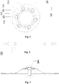
Fig. 1 : a schematic diagram of a composite sealing gasket of the present invention; -
Fig. 2 : a front view of a composite sealing gasket of the present invention; -
Fig. 3 : a schematic diagram of an inner barrel shaft seal structure of a washing machine of the present invention; -
Fig. 4 : a local schematic diagram of an inner barrel shaft seal structure of a washing machine of the present invention; -
Fig. 5 : an assembly drawing of a composite sealing gasket of the present invention; -
Fig. 6 : a schematic diagram of a segmented convex rib of a composite sealing gasket of the present invention; and -
Fig. 7 : an assembly schematic diagram of an inner barrel shaft seal structure of a washing machine of the present invention. - Reference Signs: 1. composite sealing gasket, 2. metallic framework, 3. rubber gasket, 4. first annular convex rib, 5. arc-shaped inner tooth, 6. bolt through hole, 7. second annular convex rib, 8. positioning structure, 9. center hole, 10. inner barrel shaft flange, 11. inner barrel flange, 12. bolt, 13. inner barrel shaft, 14. non-circular center hole, 15. segmented convex rib, 16. arc-shaped protrusion, 17. arc-shaped notch, and 18. positioning hole.
- In order to make the above-mentioned objects, features and advantages of the present invention more obvious and comprehensible, the present invention is further described in detail below with reference to the drawings and the specific embodiments.
- As shown in
Fig. 1 to Fig. 7 , an inner barrel shaft seal mounting structure of a washing machine, provided by the present invention, comprises aninner barrel flange 11 and aninner barrel shaft 13 which are arranged at an inner barrel bottom. The upper end part of theinner barrel shaft 13 is a flange mounting structure, theinner barrel flange 11 is in seal connection with an innerbarrel shaft flange 10. Acomposite sealing gasket 1 is arranged between theinner barrel flange 11 and the innerbarrel shaft flange 10. Thecomposite sealing gasket 1 comprises ametallic framework 2 and arubber gasket 3 which are combined into one piece through vulcanization. - As shown in
Fig. 7 , the inner barrel bottom of the washing machine is sealed, i.e., theinner barrel flange 11 is in seal connection with an inner barrel bottom. The upper end part of theinner barrel shaft 13 is the flange mounting structure, theinner barrel flange 11 is also in seal connection with the innerbarrel shaft flange 10, and the inner barrel is a water containing structure. - As shown in
Fig. 1 , in this embodiment, acomposite sealing gasket 1 is of a flat annular structure. Acenter hole 9 is formed in the middle of thecomposite sealing gasket 1. And a first annular convex rib 4 is arranged on the upper surface and/or lower surface of thecomposite sealing gasket 1 around thecenter hole 9. - As shown in
Fig. 1 , in this embodiment, a plurality of bolt throughholes 6 are distributed in thecomposite sealing gasket 1 in a circumference direction. A second annular convex rib 7 is arranged at an outer ring of each bolt throughhole 6 on the upper surface and/or lower surface of thecomposite sealing gasket 1. Preferably, a segmentedconvex rib 15 is connected between every two adjacent second annular convex ribs 7. And more preferably, circumference traces of a plurality of segmentedconvex ribs 15 are same and are concentric with the first annular convex rib 4. - As shown in
Fig. 2 andFig. 7 , in this embodiment, thepositioning structures 8 protrude from the surface of thecomposite sealing gasket 1. Preferably, thepositioning structures 8 are positioning columns, and positioning holes 18 matched with the positioning columns are formed in the innerbarrel shaft flange 10. - Preferably, in this embodiment, at least one positioning column protrudes from the lower surface of an annular rubber body, the positioning column is located between two bolt through
holes 6. And thepositioning hole 18 matched with the positioning column is formed in the innerbarrel shaft flange 10. - As shown in
Fig. 6 , in this embodiment, the positioning structure of the composite sealing gasket adopts a positioning column manner and/or adopts a manner that a non-circular center hole 14 is matched with theinner barrel shaft 13. - As shown in
Fig. 1 , in this embodiment, both themetallic framework 2 and therubber gasket 3 are of annular structures and are bonded with each other through vulcanization. Therubber gasket 3 is arranged at an inner ring of themetallic framework 2 and forms a lining of themetallic framework 2. Therubber gasket 3 and themetallic framework 2 are combined to form the flat annularcomposite sealing gasket 1. An inner ring of themetallic framework 2 serves as a combination part which is bonded to therubber gasket 3 through vulcanization, and the combination part is formed by multiple sections of curves which are successively connected. - As shown in
Fig. 1 andFig. 6 , in this embodiment, therubber gasket 3 comprises an annular rubber body. An outer ring of the annular rubber body is bonded to themetallic framework 2 through vulcanization. An inner ring of the annular rubber body forms acenter hole 9, and a first annular convex rib 4 is arranged on the upper surface and/or lower surface of the annular rubber body around thecenter hole 9. A plurality of bolt throughholes 6 are distributed outside the first annular convex rib 4 in a circumference direction. And a second annular convex rib 7 is arranged at an outer ring of each bolt throughhole 6 on the upper surface and/or lower surface of the annular rubber body. A segmentedconvex rib 15 is connected between every two adjacent second annular convex ribs 7. And preferably, circumference traces of a plurality of segmented convex ribs are same and are concentric with the first annular convex rib 4. - As shown in
Fig. 6 , in this embodiment, horizontal planes of the upper and lower surfaces of the annular rubber body are same with that of the upper and lower surfaces of themetallic framework 2 respectively. There is a smooth transition at a vulcanization bonding position. Protruding heights of the first annular convex rib 4 and the second annular convex ribs 7 protrude from the surface of thecomposite sealing gasket 1 are same. - Preferably, in this embodiment, the protruding height of the first annular convex rib 4 and the second annular convex ribs 7 are relatively small, for example 0.8cm. Thus, the
composite sealing gasket 1 can exert a better sealing action, and the condition that a gap is still generated after theinner barrel flange 11 and the innerbarrel shaft flange 10 in rigid contact is prevented. - As shown in
Fig. 5 , in this embodiment, both the bolt throughholes 6 and thepositioning columns 8 partially protrude from an outer ring of the annular rubber body to form arc-shapedprotrusions 16. And a plurality of arc-shapednotches 17 matched with the arc-shapedprotrusions 16 at the outer ring of the annular rubber body are formed in the inner ring of themetallic framework 2. - Further, an area of contact between the
metallic framework 2 and therubber gasket 3 is further increased. Thus, the bonding strength between themetallic framework 2 and therubber gasket 3 is improved. - Preferably, in this embodiment, the
positioning structures 8 have a height of 6mm to 10mm. - As shown in
Fig. 7 , in this embodiment, during the mounting of the inner barrel shaft seal mounting structure of the washing machine, firstly, theinner barrel shaft 13 penetrates through an outer barrel bottom, theinner barrel shaft 13 and the outer barrel bottom are sealed. A reducer and a motor are mounted at the outer barrel bottom. Then, thecomposite sealing gasket 1 is positioned on the innerbarrel shaft flange 10. Then, theinner barrel flange 11 fixed to an inner barrel bottom is placed on thecomposite sealing gasket 1. And finally,bolts 12 are mounted and fixed. During mounting, thecomposite sealing gasket 1 is positioned on the innerbarrel shaft flange 10 through thepositioning columns 8, and theinner barrel flange 11, thecomposite sealing gasket 1 and the innerbarrel shaft flange 10 are relatively fixed by using thebolts 12 to penetrate through theinner barrel flange 11, thecomposite sealing gasket 1 and the innerbarrel shaft flange 10 sequentially. - Preferably, in this embodiment, the positions of the inner
barrel shaft flange 10 and thecomposite sealing gasket 1 are relatively fixed after the convex ends of thepositioning structures 8 are matched with the positioning holes 18 of the inner barrel shaft flange. The bolt holes of the innerbarrel shaft flange 10 and corresponding bolt through holes of thecomposite sealing gasket 1 are in one-to-one correspondence and cannot relatively move. Then, corresponding positions of the bolt holes of theinner barrel flange 11 and the bolt throughholes 6 of the composite sealing gasket are adjusted, and thebolts 12 are mounted after adjustment is completed. Thepositioning structures 8 of the composite sealing gasket have the functions that relative positions of thecomposite sealing gasket 1 and the innerbarrel shaft flange 10 are fixed to facilitate mounting. A relative area of contact between thecomposite sealing gasket 1 and the innerbarrel shaft flange 10 is reduced. The abrasion caused by relative movement between thecomposite sealing gasket 1 and the innerbarrel shaft flange 10 is alleviated, so that the service life of thecomposite sealing gasket 1 is prolonged. - During operation of the washing machine, the motor drives the
inner barrel shaft 13 to rotate and thus drives the inner barrel to rotate. In order to prevent water in the inner barrel from leaking into the outer barrel through theinner barrel shaft 13, simultaneously bear radial forces and axial forces of the innerbarrel shaft flange 10 and theinner barrel flange 11 and prevent the innerbarrel shaft flange 10 and theinner barrel flange 11 from loosening, shaking and water-leaking problems, the present invention adopts thecomposite sealing gasket 1 which can be used for effectively solving the above-mentioned problems. - What described above are only preferred embodiments of the present invention, and it should be noted that, without departing from the principle of the present invention, various changes and modifications made by those skilled in the art shall all be covered within the scope of the technical solution of the present invention.
Claims (12)
- An inner barrel shaft seal mounting structure of a washing machine, comprising an inner barrel flange arranged at an inner barrel bottom and an inner barrel shaft, and an upper end part of the inner barrel shaft being a flange mounting structure, and the inner barrel flange being in seal connection with an inner barrel shaft flange; wherein,
a composite sealing gasket is arranged between the inner barrel flange and the inner barrel shaft flange, and the composite sealing gasket comprises a metallic framework and a rubber gasket which are combined into one piece through vulcanization. - The inner barrel shaft seal mounting structure of the washing machine according to claim 1, characterized in that the composite sealing gasket is of a flat annular structure, a center hole is formed in the middle of the composite sealing gasket, and a first annular convex rib is arranged on an upper surface and/or a lower surface of the composite sealing gasket around the center hole.
- The inner barrel shaft seal mounting structure of the washing machine according to claim 1, characterized in that a plurality of bolt through holes are distributed in a circumference direction of the composite sealing gasket, a second annular convex rib is arranged at an outer ring of each bolt through hole on an upper surface and/or a lower surface of the composite sealing gasket,
preferably, a segmented convex rib is connected between every two adjacent second annular convex ribs, and
more preferably, circumference traces of a plurality of segmented convex ribs are same and are concentric with the first annular convex rib. - The inner barrel shaft seal mounting structure of the washing machine according to claim 1, characterized in that a positioning structure is arranged between the composite sealing gasket and the inner barrel shaft flange, preferably, the positioning structure is a positioning column which protrude from a surface of the composite sealing gasket, and a positioning hole matched with the positioning column is formed in the inner barrel shaft flange.
- The inner barrel shaft seal mounting structure of the washing machine according to claim 1, characterized in that both the metallic framework and the rubber gasket are of annular structures, and are concentrically arranged and bonded together with each other along the radial direction through vulcanization.
- The inner barrel shaft seal mounting structure of the washing machine according to claim 5, characterized in that the rubber gasket is arranged at an inner ring of the metallic framework and forms a lining of the metallic framework, and the rubber gasket and the metallic framework are combined to form the composite sealing gasket with the flat annular structure.
- The inner barrel shaft seal mounting structure of the washing machine according to claim 6, characterized in that the inner ring of the metallic framework serves as a combination part which is bonded to the rubber gasket through vulcanization, and the combination part is formed by multiple sections of curves which are successively connected.
- The inner barrel shaft seal mounting structure of the washing machine according to claim 6, characterized in that the rubber gasket comprises an annular rubber body,
an outer ring of the annular rubber body is bonded to the metallic framework through vulcanization,
an inner ring of the annular rubber body forms a center hole,
a first annular convex rib is arranged on an upper surface and/or a lower surface of the annular rubber body around the center hole,
a plurality of bolt through holes are distributed outside the first annular convex rib in a circumference direction, and
a second annular convex rib is arranged at an outer ring of each bolt through hole on the upper surface and/or lower surface of the annular rubber body. - The inner barrel shaft seal mounting structure of the washing machine according to claim 8, characterized in that a segmented convex rib is connected between every two adjacent second annular convex ribs, and preferably, circumference traces of a plurality of segmented convex ribs are same and are concentric with the first annular convex rib.
- The inner barrel shaft seal mounting structure of the washing machine according to claim 8, characterized in that horizontal planes of the upper and lower surfaces of the annular rubber body are same with that of the upper and lower surfaces of the metallic framework respectively,
there is a smooth transition at a vulcanization bonding position,
the first annular convex rib and the second annular convex ribs protrude from the surface of the composite sealing gasket, and
preferably, protruding heights of the first annular convex rib and second annular convex ribs are same . - The inner barrel shaft seal mounting structure of the washing machine according to claim 8, characterized in that at least one positioning column protrudes from the lower surface of the annular rubber body, and a positioning hole matched with the positioning column is formed in the inner barrel shaft flange and is located between two bolt through holes.
- The inner barrel shaft seal mounting structure of the washing machine according to claim 8, characterized in that both the bolt through hole and the positioning column partially protrude from an outer ring of the annular rubber body to form arc-shaped protrusions, and
a plurality of arc-shaped notches matched with the arc-shaped protrusions at the outer ring of the annular rubber body are formed in the inner ring of the metallic framework.
Applications Claiming Priority (2)
| Application Number | Priority Date | Filing Date | Title |
|---|---|---|---|
| CN201510222270.1A CN106192295B (en) | 2015-05-05 | 2015-05-05 | A sealing installation structure for the inner barrel shaft of a washing machine |
| PCT/CN2015/095300 WO2016176985A1 (en) | 2015-05-05 | 2015-11-23 | Shaft seal installation structure of washing machine inner barrel |
Publications (2)
| Publication Number | Publication Date |
|---|---|
| EP3293301A1 true EP3293301A1 (en) | 2018-03-14 |
| EP3293301A4 EP3293301A4 (en) | 2018-05-02 |
Family
ID=57217326
Family Applications (1)
| Application Number | Title | Priority Date | Filing Date |
|---|---|---|---|
| EP15891228.7A Withdrawn EP3293301A4 (en) | 2015-05-05 | 2015-11-23 | Shaft seal installation structure of washing machine inner barrel |
Country Status (6)
| Country | Link |
|---|---|
| US (1) | US20180156335A1 (en) |
| EP (1) | EP3293301A4 (en) |
| JP (1) | JP6678962B2 (en) |
| KR (1) | KR20180002709A (en) |
| CN (1) | CN106192295B (en) |
| WO (1) | WO2016176985A1 (en) |
Cited By (1)
| Publication number | Priority date | Publication date | Assignee | Title |
|---|---|---|---|---|
| CN114645429A (en) * | 2020-12-18 | 2022-06-21 | 青岛海尔洗衣机有限公司 | Washing machine and control method thereof |
Families Citing this family (9)
| Publication number | Priority date | Publication date | Assignee | Title |
|---|---|---|---|---|
| CN108179591B (en) * | 2016-12-08 | 2021-10-08 | 合肥海尔滚筒洗衣机有限公司 | a washing machine |
| KR102639680B1 (en) * | 2016-12-23 | 2024-02-26 | 삼성전자주식회사 | Washing machine |
| CN107513842B (en) * | 2017-09-13 | 2022-09-09 | 青岛海尔洗衣机有限公司 | An assembly structure of a pulsator and an inner tub and a pulsator washing machine |
| CN109667107A (en) * | 2017-10-16 | 2019-04-23 | 青岛海尔滚筒洗衣机有限公司 | A kind of inner cylinder and roller washing machine of roller washing machine |
| KR102426087B1 (en) * | 2017-11-29 | 2022-07-28 | 엘지전자 주식회사 | Washing machine |
| US10907293B2 (en) | 2017-11-30 | 2021-02-02 | Whirlpool Corporation | Structural block for supporting a rotating drum within a laundry appliance |
| CN108799662A (en) * | 2018-06-28 | 2018-11-13 | 江阴市恒润重工股份有限公司 | Gas conveys special flange component |
| JP7125057B2 (en) * | 2018-10-05 | 2022-08-24 | 内山工業株式会社 | gasket |
| CN114635968B (en) * | 2020-12-16 | 2025-09-09 | 无锡小天鹅电器有限公司 | Sealing device, clutch and clothes treating device |
Family Cites Families (25)
| Publication number | Priority date | Publication date | Assignee | Title |
|---|---|---|---|---|
| JPS5842865A (en) * | 1981-09-07 | 1983-03-12 | Arai Pump Mfg Co Ltd | Metallic casket |
| US4673187A (en) * | 1985-07-09 | 1987-06-16 | Fluorocarbon Company | Bimetallic spiral wound gasket |
| JPH02267350A (en) * | 1989-04-08 | 1990-11-01 | Yuusan Gasket Kk | Cylinder head gasket |
| US5105636A (en) * | 1991-01-03 | 1992-04-21 | White Consolidated Industries, Inc. | Bearing and seal system for fabric treatment machines |
| JP3247567B2 (en) * | 1995-02-01 | 2002-01-15 | 本田技研工業株式会社 | Gasket for intake manifold |
| US6024496A (en) * | 1998-01-06 | 2000-02-15 | Delta Electronics, Inc. | Shaft coupling arrangement including oil sleeve bearing and oil supply |
| TW503288B (en) * | 1999-03-26 | 2002-09-21 | Toshiba Corp | Washing machine serving also for dehydration |
| ITMI991135A1 (en) * | 1999-05-24 | 2000-11-24 | Rolf S P A | BOX-TYPE SEALING COMPLEX IN PARTICULAR FOR VEHICLE AXLES |
| US6241782B1 (en) * | 1999-11-05 | 2001-06-05 | Maytag Corporation | Horizontal axis washing machine incorporating flush tumble cycle |
| US6869081B1 (en) * | 2002-12-20 | 2005-03-22 | Jjenco, Inc. | Constant seating stress gasket system |
| DE10324978A1 (en) * | 2003-06-03 | 2004-12-30 | Federal-Mogul Sealing Systems Gmbh | Process and production of a flat gasket and flat gasket |
| JP4538238B2 (en) * | 2004-01-07 | 2010-09-08 | 三菱電線工業株式会社 | gasket |
| US20060145429A1 (en) * | 2004-09-29 | 2006-07-06 | Arvid Casler | High dielectric fluid joint gasket |
| JP4324607B2 (en) * | 2006-08-11 | 2009-09-02 | 日本ピラー工業株式会社 | Non-asbestos gasket |
| US8191933B2 (en) * | 2008-07-16 | 2012-06-05 | General Electric Company | Extrusion resistant gasket face seal |
| WO2010036388A1 (en) * | 2008-09-29 | 2010-04-01 | Parker-Hannifin Corporation | Hygienic tube fitting gasket |
| CN201531693U (en) * | 2009-09-16 | 2010-07-21 | 青岛开世密封工业有限公司 | Flange seal gasket |
| US8833771B2 (en) * | 2009-12-18 | 2014-09-16 | Federal-Mogul Corporation | Gasket assembly with improved locating and retention pin and method of construction thereof |
| US9388924B2 (en) * | 2011-03-18 | 2016-07-12 | Advanced Sealing, Inc. | Alky-one gasket |
| JP5723846B2 (en) * | 2012-10-04 | 2015-05-27 | 内山工業株式会社 | gasket |
| CN202972286U (en) * | 2012-12-21 | 2013-06-05 | 无锡市华尔泰机械制造有限公司 | Stainless steel spacer for flanges |
| CN103088598B (en) * | 2013-01-30 | 2015-05-20 | 南京创维家用电器有限公司 | Anti-leakage pulsator washing machine |
| CN105247263B (en) * | 2013-05-31 | 2017-09-19 | 协和工业株式会社 | Flange connection and the seal for the structure |
| CN204253876U (en) * | 2014-09-28 | 2015-04-08 | 青岛海尔洗衣机有限公司 | A kind of packing ring and reduction clutch of washing machine |
| CN204199044U (en) * | 2014-09-29 | 2015-03-11 | 青岛海尔洗衣机有限公司 | A kind of automatic washing machine |
-
2015
- 2015-05-05 CN CN201510222270.1A patent/CN106192295B/en active Active
- 2015-11-23 JP JP2017557377A patent/JP6678962B2/en not_active Expired - Fee Related
- 2015-11-23 WO PCT/CN2015/095300 patent/WO2016176985A1/en not_active Ceased
- 2015-11-23 EP EP15891228.7A patent/EP3293301A4/en not_active Withdrawn
- 2015-11-23 US US15/571,586 patent/US20180156335A1/en not_active Abandoned
- 2015-11-23 KR KR1020177033962A patent/KR20180002709A/en not_active Ceased
Cited By (1)
| Publication number | Priority date | Publication date | Assignee | Title |
|---|---|---|---|---|
| CN114645429A (en) * | 2020-12-18 | 2022-06-21 | 青岛海尔洗衣机有限公司 | Washing machine and control method thereof |
Also Published As
| Publication number | Publication date |
|---|---|
| US20180156335A1 (en) | 2018-06-07 |
| WO2016176985A1 (en) | 2016-11-10 |
| EP3293301A4 (en) | 2018-05-02 |
| JP2018514326A (en) | 2018-06-07 |
| CN106192295A (en) | 2016-12-07 |
| KR20180002709A (en) | 2018-01-08 |
| JP6678962B2 (en) | 2020-04-15 |
| CN106192295B (en) | 2019-04-19 |
Similar Documents
| Publication | Publication Date | Title |
|---|---|---|
| US20180156335A1 (en) | Inner barrel shaft seal mounting structure of washing machine | |
| EP3305971A1 (en) | Sealing installation structure of inner barrel bottom and flange of washing machine | |
| CN1246552A (en) | Osmotic washing machine, its control method and bucket cover | |
| CN101988252A (en) | Tumbling barrel of high-efficiency washing machine | |
| CN105088605A (en) | A reciprocating squeezing type and rotation type washing machine | |
| CN1236127C (en) | Float type sealing device of water-saving full-automatic washing machine | |
| CN106637794A (en) | Wave-wheel type automatic washing machine | |
| CN107142673A (en) | Washing machine and inner tank of washing machine | |
| CN107475993A (en) | Washing machine | |
| CN102234907B (en) | A kind of washing machine aeroseal method and device thereof | |
| CN103742476A (en) | Spirally swinging hydraulic cylinder | |
| CN222550320U (en) | A filter that is easy to replace filter element | |
| CN204690352U (en) | Washing machine | |
| CN209456739U (en) | A kind of balance ring mounting structure and interior bucket and washing machine with the structure | |
| CN208562876U (en) | Front-loading washing machine and its spray system | |
| CN105432711B (en) | A kind of flour stranding machine for being easily installed dismounting | |
| CN106273631A (en) | An environmentally friendly biofuel manufacturing equipment for boilers | |
| CN105155195A (en) | Washing machine impeller | |
| CN213232819U (en) | Rubbing type washing machine | |
| CN104226183B (en) | A kind of central shaft rotating equipment bearing | |
| CN205288297U (en) | Bottom bearing assembly is used to sanitary -grade agitator tank | |
| CN110952269A (en) | Drum washing machine | |
| CN2557553Y (en) | Water-saving fully automatic washing machine floating body type sealing device | |
| CN107916523B (en) | Washing machine with self-locking water switch | |
| CN207844529U (en) | Driving lever gravity discharge formula dust storage device, driving lever gravity discharge mechanism and driving lever |
Legal Events
| Date | Code | Title | Description |
|---|---|---|---|
| STAA | Information on the status of an ep patent application or granted ep patent |
Free format text: STATUS: THE INTERNATIONAL PUBLICATION HAS BEEN MADE |
|
| PUAI | Public reference made under article 153(3) epc to a published international application that has entered the european phase |
Free format text: ORIGINAL CODE: 0009012 |
|
| STAA | Information on the status of an ep patent application or granted ep patent |
Free format text: STATUS: REQUEST FOR EXAMINATION WAS MADE |
|
| 17P | Request for examination filed |
Effective date: 20171201 |
|
| AK | Designated contracting states |
Kind code of ref document: A1 Designated state(s): AL AT BE BG CH CY CZ DE DK EE ES FI FR GB GR HR HU IE IS IT LI LT LU LV MC MK MT NL NO PL PT RO RS SE SI SK SM TR |
|
| AX | Request for extension of the european patent |
Extension state: BA ME |
|
| A4 | Supplementary search report drawn up and despatched |
Effective date: 20180406 |
|
| RIC1 | Information provided on ipc code assigned before grant |
Ipc: D06F 37/20 20060101ALI20180329BHEP Ipc: D06F 37/30 20060101AFI20180329BHEP Ipc: F16L 23/18 20060101ALI20180329BHEP |
|
| DAV | Request for validation of the european patent (deleted) | ||
| DAX | Request for extension of the european patent (deleted) | ||
| STAA | Information on the status of an ep patent application or granted ep patent |
Free format text: STATUS: THE APPLICATION IS DEEMED TO BE WITHDRAWN |
|
| 18D | Application deemed to be withdrawn |
Effective date: 20181106 |