EP3293068A2 - Vehicle and control method thereof - Google Patents
Vehicle and control method thereof Download PDFInfo
- Publication number
- EP3293068A2 EP3293068A2 EP17184831.0A EP17184831A EP3293068A2 EP 3293068 A2 EP3293068 A2 EP 3293068A2 EP 17184831 A EP17184831 A EP 17184831A EP 3293068 A2 EP3293068 A2 EP 3293068A2
- Authority
- EP
- European Patent Office
- Prior art keywords
- gear
- vehicle
- moving start
- clutch
- controller
- Prior art date
- Legal status (The legal status is an assumption and is not a legal conclusion. Google has not performed a legal analysis and makes no representation as to the accuracy of the status listed.)
- Withdrawn
Links
Images




Classifications
-
- B—PERFORMING OPERATIONS; TRANSPORTING
- B60—VEHICLES IN GENERAL
- B60W—CONJOINT CONTROL OF VEHICLE SUB-UNITS OF DIFFERENT TYPE OR DIFFERENT FUNCTION; CONTROL SYSTEMS SPECIALLY ADAPTED FOR HYBRID VEHICLES; ROAD VEHICLE DRIVE CONTROL SYSTEMS FOR PURPOSES NOT RELATED TO THE CONTROL OF A PARTICULAR SUB-UNIT
- B60W30/00—Purposes of road vehicle drive control systems not related to the control of a particular sub-unit, e.g. of systems using conjoint control of vehicle sub-units
- B60W30/18—Propelling the vehicle
- B60W30/18009—Propelling the vehicle related to particular drive situations
- B60W30/18027—Drive off, accelerating from standstill
-
- B—PERFORMING OPERATIONS; TRANSPORTING
- B60—VEHICLES IN GENERAL
- B60K—ARRANGEMENT OR MOUNTING OF PROPULSION UNITS OR OF TRANSMISSIONS IN VEHICLES; ARRANGEMENT OR MOUNTING OF PLURAL DIVERSE PRIME-MOVERS IN VEHICLES; AUXILIARY DRIVES FOR VEHICLES; INSTRUMENTATION OR DASHBOARDS FOR VEHICLES; ARRANGEMENTS IN CONNECTION WITH COOLING, AIR INTAKE, GAS EXHAUST OR FUEL SUPPLY OF PROPULSION UNITS IN VEHICLES
- B60K17/00—Arrangement or mounting of transmissions in vehicles
- B60K17/04—Arrangement or mounting of transmissions in vehicles characterised by arrangement, location or kind of gearing
- B60K17/16—Arrangement or mounting of transmissions in vehicles characterised by arrangement, location or kind of gearing of differential gearing
- B60K17/20—Arrangement or mounting of transmissions in vehicles characterised by arrangement, location or kind of gearing of differential gearing in which the differential movement is limited
-
- B—PERFORMING OPERATIONS; TRANSPORTING
- B60—VEHICLES IN GENERAL
- B60K—ARRANGEMENT OR MOUNTING OF PROPULSION UNITS OR OF TRANSMISSIONS IN VEHICLES; ARRANGEMENT OR MOUNTING OF PLURAL DIVERSE PRIME-MOVERS IN VEHICLES; AUXILIARY DRIVES FOR VEHICLES; INSTRUMENTATION OR DASHBOARDS FOR VEHICLES; ARRANGEMENTS IN CONNECTION WITH COOLING, AIR INTAKE, GAS EXHAUST OR FUEL SUPPLY OF PROPULSION UNITS IN VEHICLES
- B60K17/00—Arrangement or mounting of transmissions in vehicles
- B60K17/04—Arrangement or mounting of transmissions in vehicles characterised by arrangement, location or kind of gearing
- B60K17/16—Arrangement or mounting of transmissions in vehicles characterised by arrangement, location or kind of gearing of differential gearing
-
- B—PERFORMING OPERATIONS; TRANSPORTING
- B60—VEHICLES IN GENERAL
- B60K—ARRANGEMENT OR MOUNTING OF PROPULSION UNITS OR OF TRANSMISSIONS IN VEHICLES; ARRANGEMENT OR MOUNTING OF PLURAL DIVERSE PRIME-MOVERS IN VEHICLES; AUXILIARY DRIVES FOR VEHICLES; INSTRUMENTATION OR DASHBOARDS FOR VEHICLES; ARRANGEMENTS IN CONNECTION WITH COOLING, AIR INTAKE, GAS EXHAUST OR FUEL SUPPLY OF PROPULSION UNITS IN VEHICLES
- B60K17/00—Arrangement or mounting of transmissions in vehicles
- B60K17/04—Arrangement or mounting of transmissions in vehicles characterised by arrangement, location or kind of gearing
- B60K17/16—Arrangement or mounting of transmissions in vehicles characterised by arrangement, location or kind of gearing of differential gearing
- B60K17/165—Arrangement or mounting of transmissions in vehicles characterised by arrangement, location or kind of gearing of differential gearing provided between independent half axles
-
- B—PERFORMING OPERATIONS; TRANSPORTING
- B60—VEHICLES IN GENERAL
- B60K—ARRANGEMENT OR MOUNTING OF PROPULSION UNITS OR OF TRANSMISSIONS IN VEHICLES; ARRANGEMENT OR MOUNTING OF PLURAL DIVERSE PRIME-MOVERS IN VEHICLES; AUXILIARY DRIVES FOR VEHICLES; INSTRUMENTATION OR DASHBOARDS FOR VEHICLES; ARRANGEMENTS IN CONNECTION WITH COOLING, AIR INTAKE, GAS EXHAUST OR FUEL SUPPLY OF PROPULSION UNITS IN VEHICLES
- B60K17/00—Arrangement or mounting of transmissions in vehicles
- B60K17/30—Arrangement or mounting of transmissions in vehicles the ultimate propulsive elements, e.g. ground wheels, being steerable
-
- B—PERFORMING OPERATIONS; TRANSPORTING
- B60—VEHICLES IN GENERAL
- B60K—ARRANGEMENT OR MOUNTING OF PROPULSION UNITS OR OF TRANSMISSIONS IN VEHICLES; ARRANGEMENT OR MOUNTING OF PLURAL DIVERSE PRIME-MOVERS IN VEHICLES; AUXILIARY DRIVES FOR VEHICLES; INSTRUMENTATION OR DASHBOARDS FOR VEHICLES; ARRANGEMENTS IN CONNECTION WITH COOLING, AIR INTAKE, GAS EXHAUST OR FUEL SUPPLY OF PROPULSION UNITS IN VEHICLES
- B60K17/00—Arrangement or mounting of transmissions in vehicles
- B60K17/34—Arrangement or mounting of transmissions in vehicles for driving both front and rear wheels, e.g. four wheel drive vehicles
- B60K17/344—Arrangement or mounting of transmissions in vehicles for driving both front and rear wheels, e.g. four wheel drive vehicles having a transfer gear
-
- B—PERFORMING OPERATIONS; TRANSPORTING
- B60—VEHICLES IN GENERAL
- B60K—ARRANGEMENT OR MOUNTING OF PROPULSION UNITS OR OF TRANSMISSIONS IN VEHICLES; ARRANGEMENT OR MOUNTING OF PLURAL DIVERSE PRIME-MOVERS IN VEHICLES; AUXILIARY DRIVES FOR VEHICLES; INSTRUMENTATION OR DASHBOARDS FOR VEHICLES; ARRANGEMENTS IN CONNECTION WITH COOLING, AIR INTAKE, GAS EXHAUST OR FUEL SUPPLY OF PROPULSION UNITS IN VEHICLES
- B60K23/00—Arrangement or mounting of control devices for vehicle transmissions, or parts thereof, not otherwise provided for
- B60K23/04—Arrangement or mounting of control devices for vehicle transmissions, or parts thereof, not otherwise provided for for differential gearing
-
- B—PERFORMING OPERATIONS; TRANSPORTING
- B60—VEHICLES IN GENERAL
- B60K—ARRANGEMENT OR MOUNTING OF PROPULSION UNITS OR OF TRANSMISSIONS IN VEHICLES; ARRANGEMENT OR MOUNTING OF PLURAL DIVERSE PRIME-MOVERS IN VEHICLES; AUXILIARY DRIVES FOR VEHICLES; INSTRUMENTATION OR DASHBOARDS FOR VEHICLES; ARRANGEMENTS IN CONNECTION WITH COOLING, AIR INTAKE, GAS EXHAUST OR FUEL SUPPLY OF PROPULSION UNITS IN VEHICLES
- B60K23/00—Arrangement or mounting of control devices for vehicle transmissions, or parts thereof, not otherwise provided for
- B60K23/08—Arrangement or mounting of control devices for vehicle transmissions, or parts thereof, not otherwise provided for for changing number of driven wheels, for switching from driving one axle to driving two or more axles
-
- B—PERFORMING OPERATIONS; TRANSPORTING
- B60—VEHICLES IN GENERAL
- B60K—ARRANGEMENT OR MOUNTING OF PROPULSION UNITS OR OF TRANSMISSIONS IN VEHICLES; ARRANGEMENT OR MOUNTING OF PLURAL DIVERSE PRIME-MOVERS IN VEHICLES; AUXILIARY DRIVES FOR VEHICLES; INSTRUMENTATION OR DASHBOARDS FOR VEHICLES; ARRANGEMENTS IN CONNECTION WITH COOLING, AIR INTAKE, GAS EXHAUST OR FUEL SUPPLY OF PROPULSION UNITS IN VEHICLES
- B60K5/00—Arrangement or mounting of internal-combustion or jet-propulsion units
- B60K5/02—Arrangement or mounting of internal-combustion or jet-propulsion units with the engine main axis, e.g. crankshaft axis, substantially in or parallel to the longitudinal centre line of the vehicle
-
- B—PERFORMING OPERATIONS; TRANSPORTING
- B60—VEHICLES IN GENERAL
- B60N—SEATS SPECIALLY ADAPTED FOR VEHICLES; VEHICLE PASSENGER ACCOMMODATION NOT OTHERWISE PROVIDED FOR
- B60N2/00—Seats specially adapted for vehicles; Arrangement or mounting of seats in vehicles
- B60N2/005—Arrangement or mounting of seats in vehicles, e.g. dismountable auxiliary seats
- B60N2/01—Arrangement of seats relative to one another
-
- B—PERFORMING OPERATIONS; TRANSPORTING
- B60—VEHICLES IN GENERAL
- B60N—SEATS SPECIALLY ADAPTED FOR VEHICLES; VEHICLE PASSENGER ACCOMMODATION NOT OTHERWISE PROVIDED FOR
- B60N2/00—Seats specially adapted for vehicles; Arrangement or mounting of seats in vehicles
- B60N2/24—Seats specially adapted for vehicles; Arrangement or mounting of seats in vehicles for particular purposes or particular vehicles
- B60N2/38—Seats specially adapted for vehicles; Arrangement or mounting of seats in vehicles for particular purposes or particular vehicles specially constructed for use on tractors or like off-road vehicles
-
- B—PERFORMING OPERATIONS; TRANSPORTING
- B60—VEHICLES IN GENERAL
- B60W—CONJOINT CONTROL OF VEHICLE SUB-UNITS OF DIFFERENT TYPE OR DIFFERENT FUNCTION; CONTROL SYSTEMS SPECIALLY ADAPTED FOR HYBRID VEHICLES; ROAD VEHICLE DRIVE CONTROL SYSTEMS FOR PURPOSES NOT RELATED TO THE CONTROL OF A PARTICULAR SUB-UNIT
- B60W10/00—Conjoint control of vehicle sub-units of different type or different function
- B60W10/02—Conjoint control of vehicle sub-units of different type or different function including control of driveline clutches
-
- B—PERFORMING OPERATIONS; TRANSPORTING
- B60—VEHICLES IN GENERAL
- B60W—CONJOINT CONTROL OF VEHICLE SUB-UNITS OF DIFFERENT TYPE OR DIFFERENT FUNCTION; CONTROL SYSTEMS SPECIALLY ADAPTED FOR HYBRID VEHICLES; ROAD VEHICLE DRIVE CONTROL SYSTEMS FOR PURPOSES NOT RELATED TO THE CONTROL OF A PARTICULAR SUB-UNIT
- B60W10/00—Conjoint control of vehicle sub-units of different type or different function
- B60W10/04—Conjoint control of vehicle sub-units of different type or different function including control of propulsion units
- B60W10/06—Conjoint control of vehicle sub-units of different type or different function including control of propulsion units including control of combustion engines
-
- B—PERFORMING OPERATIONS; TRANSPORTING
- B60—VEHICLES IN GENERAL
- B60W—CONJOINT CONTROL OF VEHICLE SUB-UNITS OF DIFFERENT TYPE OR DIFFERENT FUNCTION; CONTROL SYSTEMS SPECIALLY ADAPTED FOR HYBRID VEHICLES; ROAD VEHICLE DRIVE CONTROL SYSTEMS FOR PURPOSES NOT RELATED TO THE CONTROL OF A PARTICULAR SUB-UNIT
- B60W10/00—Conjoint control of vehicle sub-units of different type or different function
- B60W10/12—Conjoint control of vehicle sub-units of different type or different function including control of differentials
- B60W10/16—Axle differentials, e.g. for dividing torque between left and right wheels
-
- B—PERFORMING OPERATIONS; TRANSPORTING
- B60—VEHICLES IN GENERAL
- B60W—CONJOINT CONTROL OF VEHICLE SUB-UNITS OF DIFFERENT TYPE OR DIFFERENT FUNCTION; CONTROL SYSTEMS SPECIALLY ADAPTED FOR HYBRID VEHICLES; ROAD VEHICLE DRIVE CONTROL SYSTEMS FOR PURPOSES NOT RELATED TO THE CONTROL OF A PARTICULAR SUB-UNIT
- B60W30/00—Purposes of road vehicle drive control systems not related to the control of a particular sub-unit, e.g. of systems using conjoint control of vehicle sub-units
- B60W30/02—Control of vehicle driving stability
- B60W30/045—Improving turning performance
-
- B—PERFORMING OPERATIONS; TRANSPORTING
- B60—VEHICLES IN GENERAL
- B60W—CONJOINT CONTROL OF VEHICLE SUB-UNITS OF DIFFERENT TYPE OR DIFFERENT FUNCTION; CONTROL SYSTEMS SPECIALLY ADAPTED FOR HYBRID VEHICLES; ROAD VEHICLE DRIVE CONTROL SYSTEMS FOR PURPOSES NOT RELATED TO THE CONTROL OF A PARTICULAR SUB-UNIT
- B60W30/00—Purposes of road vehicle drive control systems not related to the control of a particular sub-unit, e.g. of systems using conjoint control of vehicle sub-units
- B60W30/18—Propelling the vehicle
- B60W30/18172—Preventing, or responsive to skidding of wheels
-
- B—PERFORMING OPERATIONS; TRANSPORTING
- B60—VEHICLES IN GENERAL
- B60W—CONJOINT CONTROL OF VEHICLE SUB-UNITS OF DIFFERENT TYPE OR DIFFERENT FUNCTION; CONTROL SYSTEMS SPECIALLY ADAPTED FOR HYBRID VEHICLES; ROAD VEHICLE DRIVE CONTROL SYSTEMS FOR PURPOSES NOT RELATED TO THE CONTROL OF A PARTICULAR SUB-UNIT
- B60W30/00—Purposes of road vehicle drive control systems not related to the control of a particular sub-unit, e.g. of systems using conjoint control of vehicle sub-units
- B60W30/18—Propelling the vehicle
- B60W30/182—Selecting between different operative modes, e.g. comfort and performance modes
-
- B—PERFORMING OPERATIONS; TRANSPORTING
- B62—LAND VEHICLES FOR TRAVELLING OTHERWISE THAN ON RAILS
- B62D—MOTOR VEHICLES; TRAILERS
- B62D1/00—Steering controls, i.e. means for initiating a change of direction of the vehicle
- B62D1/02—Steering controls, i.e. means for initiating a change of direction of the vehicle vehicle-mounted
- B62D1/04—Hand wheels
-
- B—PERFORMING OPERATIONS; TRANSPORTING
- B60—VEHICLES IN GENERAL
- B60K—ARRANGEMENT OR MOUNTING OF PROPULSION UNITS OR OF TRANSMISSIONS IN VEHICLES; ARRANGEMENT OR MOUNTING OF PLURAL DIVERSE PRIME-MOVERS IN VEHICLES; AUXILIARY DRIVES FOR VEHICLES; INSTRUMENTATION OR DASHBOARDS FOR VEHICLES; ARRANGEMENTS IN CONNECTION WITH COOLING, AIR INTAKE, GAS EXHAUST OR FUEL SUPPLY OF PROPULSION UNITS IN VEHICLES
- B60K5/00—Arrangement or mounting of internal-combustion or jet-propulsion units
- B60K2005/003—Arrangement or mounting of internal-combustion or jet-propulsion units the internal combustion or jet propulsion unit is arranged between the front and the rear axle
-
- B—PERFORMING OPERATIONS; TRANSPORTING
- B60—VEHICLES IN GENERAL
- B60K—ARRANGEMENT OR MOUNTING OF PROPULSION UNITS OR OF TRANSMISSIONS IN VEHICLES; ARRANGEMENT OR MOUNTING OF PLURAL DIVERSE PRIME-MOVERS IN VEHICLES; AUXILIARY DRIVES FOR VEHICLES; INSTRUMENTATION OR DASHBOARDS FOR VEHICLES; ARRANGEMENTS IN CONNECTION WITH COOLING, AIR INTAKE, GAS EXHAUST OR FUEL SUPPLY OF PROPULSION UNITS IN VEHICLES
- B60K5/00—Arrangement or mounting of internal-combustion or jet-propulsion units
- B60K2005/006—Arrangement or mounting of internal-combustion or jet-propulsion units the internal combustion or jet propulsion unit is arranged behind the rear axle
-
- B—PERFORMING OPERATIONS; TRANSPORTING
- B60—VEHICLES IN GENERAL
- B60K—ARRANGEMENT OR MOUNTING OF PROPULSION UNITS OR OF TRANSMISSIONS IN VEHICLES; ARRANGEMENT OR MOUNTING OF PLURAL DIVERSE PRIME-MOVERS IN VEHICLES; AUXILIARY DRIVES FOR VEHICLES; INSTRUMENTATION OR DASHBOARDS FOR VEHICLES; ARRANGEMENTS IN CONNECTION WITH COOLING, AIR INTAKE, GAS EXHAUST OR FUEL SUPPLY OF PROPULSION UNITS IN VEHICLES
- B60K23/00—Arrangement or mounting of control devices for vehicle transmissions, or parts thereof, not otherwise provided for
- B60K23/04—Arrangement or mounting of control devices for vehicle transmissions, or parts thereof, not otherwise provided for for differential gearing
- B60K2023/043—Control means for varying left-right torque distribution, e.g. torque vectoring
-
- B—PERFORMING OPERATIONS; TRANSPORTING
- B60—VEHICLES IN GENERAL
- B60K—ARRANGEMENT OR MOUNTING OF PROPULSION UNITS OR OF TRANSMISSIONS IN VEHICLES; ARRANGEMENT OR MOUNTING OF PLURAL DIVERSE PRIME-MOVERS IN VEHICLES; AUXILIARY DRIVES FOR VEHICLES; INSTRUMENTATION OR DASHBOARDS FOR VEHICLES; ARRANGEMENTS IN CONNECTION WITH COOLING, AIR INTAKE, GAS EXHAUST OR FUEL SUPPLY OF PROPULSION UNITS IN VEHICLES
- B60K23/00—Arrangement or mounting of control devices for vehicle transmissions, or parts thereof, not otherwise provided for
- B60K23/04—Arrangement or mounting of control devices for vehicle transmissions, or parts thereof, not otherwise provided for for differential gearing
- B60K2023/046—Axle differential locking means
-
- B—PERFORMING OPERATIONS; TRANSPORTING
- B60—VEHICLES IN GENERAL
- B60K—ARRANGEMENT OR MOUNTING OF PROPULSION UNITS OR OF TRANSMISSIONS IN VEHICLES; ARRANGEMENT OR MOUNTING OF PLURAL DIVERSE PRIME-MOVERS IN VEHICLES; AUXILIARY DRIVES FOR VEHICLES; INSTRUMENTATION OR DASHBOARDS FOR VEHICLES; ARRANGEMENTS IN CONNECTION WITH COOLING, AIR INTAKE, GAS EXHAUST OR FUEL SUPPLY OF PROPULSION UNITS IN VEHICLES
- B60K23/00—Arrangement or mounting of control devices for vehicle transmissions, or parts thereof, not otherwise provided for
- B60K23/08—Arrangement or mounting of control devices for vehicle transmissions, or parts thereof, not otherwise provided for for changing number of driven wheels, for switching from driving one axle to driving two or more axles
- B60K2023/085—Arrangement or mounting of control devices for vehicle transmissions, or parts thereof, not otherwise provided for for changing number of driven wheels, for switching from driving one axle to driving two or more axles automatically actuated
-
- B—PERFORMING OPERATIONS; TRANSPORTING
- B60—VEHICLES IN GENERAL
- B60R—VEHICLES, VEHICLE FITTINGS, OR VEHICLE PARTS, NOT OTHERWISE PROVIDED FOR
- B60R21/00—Arrangements or fittings on vehicles for protecting or preventing injuries to occupants or pedestrians in case of accidents or other traffic risks
- B60R21/02—Occupant safety arrangements or fittings, e.g. crash pads
- B60R21/13—Roll-over protection
-
- B—PERFORMING OPERATIONS; TRANSPORTING
- B60—VEHICLES IN GENERAL
- B60W—CONJOINT CONTROL OF VEHICLE SUB-UNITS OF DIFFERENT TYPE OR DIFFERENT FUNCTION; CONTROL SYSTEMS SPECIALLY ADAPTED FOR HYBRID VEHICLES; ROAD VEHICLE DRIVE CONTROL SYSTEMS FOR PURPOSES NOT RELATED TO THE CONTROL OF A PARTICULAR SUB-UNIT
- B60W2300/00—Indexing codes relating to the type of vehicle
- B60W2300/36—Cycles; Motorcycles; Scooters
- B60W2300/362—Buggies; Quads
-
- B—PERFORMING OPERATIONS; TRANSPORTING
- B60—VEHICLES IN GENERAL
- B60W—CONJOINT CONTROL OF VEHICLE SUB-UNITS OF DIFFERENT TYPE OR DIFFERENT FUNCTION; CONTROL SYSTEMS SPECIALLY ADAPTED FOR HYBRID VEHICLES; ROAD VEHICLE DRIVE CONTROL SYSTEMS FOR PURPOSES NOT RELATED TO THE CONTROL OF A PARTICULAR SUB-UNIT
- B60W2510/00—Input parameters relating to a particular sub-units
- B60W2510/02—Clutches
- B60W2510/0208—Clutch engagement state, e.g. engaged or disengaged
-
- B—PERFORMING OPERATIONS; TRANSPORTING
- B60—VEHICLES IN GENERAL
- B60W—CONJOINT CONTROL OF VEHICLE SUB-UNITS OF DIFFERENT TYPE OR DIFFERENT FUNCTION; CONTROL SYSTEMS SPECIALLY ADAPTED FOR HYBRID VEHICLES; ROAD VEHICLE DRIVE CONTROL SYSTEMS FOR PURPOSES NOT RELATED TO THE CONTROL OF A PARTICULAR SUB-UNIT
- B60W2510/00—Input parameters relating to a particular sub-units
- B60W2510/02—Clutches
- B60W2510/0241—Clutch slip, i.e. difference between input and output speeds
-
- B—PERFORMING OPERATIONS; TRANSPORTING
- B60—VEHICLES IN GENERAL
- B60W—CONJOINT CONTROL OF VEHICLE SUB-UNITS OF DIFFERENT TYPE OR DIFFERENT FUNCTION; CONTROL SYSTEMS SPECIALLY ADAPTED FOR HYBRID VEHICLES; ROAD VEHICLE DRIVE CONTROL SYSTEMS FOR PURPOSES NOT RELATED TO THE CONTROL OF A PARTICULAR SUB-UNIT
- B60W2510/00—Input parameters relating to a particular sub-units
- B60W2510/10—Change speed gearings
-
- B—PERFORMING OPERATIONS; TRANSPORTING
- B60—VEHICLES IN GENERAL
- B60W—CONJOINT CONTROL OF VEHICLE SUB-UNITS OF DIFFERENT TYPE OR DIFFERENT FUNCTION; CONTROL SYSTEMS SPECIALLY ADAPTED FOR HYBRID VEHICLES; ROAD VEHICLE DRIVE CONTROL SYSTEMS FOR PURPOSES NOT RELATED TO THE CONTROL OF A PARTICULAR SUB-UNIT
- B60W2510/00—Input parameters relating to a particular sub-units
- B60W2510/10—Change speed gearings
- B60W2510/1005—Transmission ratio engaged
-
- B—PERFORMING OPERATIONS; TRANSPORTING
- B60—VEHICLES IN GENERAL
- B60W—CONJOINT CONTROL OF VEHICLE SUB-UNITS OF DIFFERENT TYPE OR DIFFERENT FUNCTION; CONTROL SYSTEMS SPECIALLY ADAPTED FOR HYBRID VEHICLES; ROAD VEHICLE DRIVE CONTROL SYSTEMS FOR PURPOSES NOT RELATED TO THE CONTROL OF A PARTICULAR SUB-UNIT
- B60W2510/00—Input parameters relating to a particular sub-units
- B60W2510/12—Differentials
- B60W2510/125—Locking status
-
- B—PERFORMING OPERATIONS; TRANSPORTING
- B60—VEHICLES IN GENERAL
- B60W—CONJOINT CONTROL OF VEHICLE SUB-UNITS OF DIFFERENT TYPE OR DIFFERENT FUNCTION; CONTROL SYSTEMS SPECIALLY ADAPTED FOR HYBRID VEHICLES; ROAD VEHICLE DRIVE CONTROL SYSTEMS FOR PURPOSES NOT RELATED TO THE CONTROL OF A PARTICULAR SUB-UNIT
- B60W2540/00—Input parameters relating to occupants
- B60W2540/10—Accelerator pedal position
-
- B—PERFORMING OPERATIONS; TRANSPORTING
- B60—VEHICLES IN GENERAL
- B60W—CONJOINT CONTROL OF VEHICLE SUB-UNITS OF DIFFERENT TYPE OR DIFFERENT FUNCTION; CONTROL SYSTEMS SPECIALLY ADAPTED FOR HYBRID VEHICLES; ROAD VEHICLE DRIVE CONTROL SYSTEMS FOR PURPOSES NOT RELATED TO THE CONTROL OF A PARTICULAR SUB-UNIT
- B60W2710/00—Output or target parameters relating to a particular sub-units
- B60W2710/02—Clutches
-
- B—PERFORMING OPERATIONS; TRANSPORTING
- B60—VEHICLES IN GENERAL
- B60W—CONJOINT CONTROL OF VEHICLE SUB-UNITS OF DIFFERENT TYPE OR DIFFERENT FUNCTION; CONTROL SYSTEMS SPECIALLY ADAPTED FOR HYBRID VEHICLES; ROAD VEHICLE DRIVE CONTROL SYSTEMS FOR PURPOSES NOT RELATED TO THE CONTROL OF A PARTICULAR SUB-UNIT
- B60W2710/00—Output or target parameters relating to a particular sub-units
- B60W2710/02—Clutches
- B60W2710/021—Clutch engagement state
-
- B—PERFORMING OPERATIONS; TRANSPORTING
- B60—VEHICLES IN GENERAL
- B60W—CONJOINT CONTROL OF VEHICLE SUB-UNITS OF DIFFERENT TYPE OR DIFFERENT FUNCTION; CONTROL SYSTEMS SPECIALLY ADAPTED FOR HYBRID VEHICLES; ROAD VEHICLE DRIVE CONTROL SYSTEMS FOR PURPOSES NOT RELATED TO THE CONTROL OF A PARTICULAR SUB-UNIT
- B60W2710/00—Output or target parameters relating to a particular sub-units
- B60W2710/02—Clutches
- B60W2710/021—Clutch engagement state
- B60W2710/023—Clutch engagement rate
-
- B—PERFORMING OPERATIONS; TRANSPORTING
- B60—VEHICLES IN GENERAL
- B60W—CONJOINT CONTROL OF VEHICLE SUB-UNITS OF DIFFERENT TYPE OR DIFFERENT FUNCTION; CONTROL SYSTEMS SPECIALLY ADAPTED FOR HYBRID VEHICLES; ROAD VEHICLE DRIVE CONTROL SYSTEMS FOR PURPOSES NOT RELATED TO THE CONTROL OF A PARTICULAR SUB-UNIT
- B60W2710/00—Output or target parameters relating to a particular sub-units
- B60W2710/02—Clutches
- B60W2710/027—Clutch torque
-
- B—PERFORMING OPERATIONS; TRANSPORTING
- B60—VEHICLES IN GENERAL
- B60W—CONJOINT CONTROL OF VEHICLE SUB-UNITS OF DIFFERENT TYPE OR DIFFERENT FUNCTION; CONTROL SYSTEMS SPECIALLY ADAPTED FOR HYBRID VEHICLES; ROAD VEHICLE DRIVE CONTROL SYSTEMS FOR PURPOSES NOT RELATED TO THE CONTROL OF A PARTICULAR SUB-UNIT
- B60W2710/00—Output or target parameters relating to a particular sub-units
- B60W2710/06—Combustion engines, Gas turbines
- B60W2710/0644—Engine speed
-
- B—PERFORMING OPERATIONS; TRANSPORTING
- B60—VEHICLES IN GENERAL
- B60W—CONJOINT CONTROL OF VEHICLE SUB-UNITS OF DIFFERENT TYPE OR DIFFERENT FUNCTION; CONTROL SYSTEMS SPECIALLY ADAPTED FOR HYBRID VEHICLES; ROAD VEHICLE DRIVE CONTROL SYSTEMS FOR PURPOSES NOT RELATED TO THE CONTROL OF A PARTICULAR SUB-UNIT
- B60W2710/00—Output or target parameters relating to a particular sub-units
- B60W2710/12—Differentials
- B60W2710/125—Locking status
-
- B—PERFORMING OPERATIONS; TRANSPORTING
- B60—VEHICLES IN GENERAL
- B60Y—INDEXING SCHEME RELATING TO ASPECTS CROSS-CUTTING VEHICLE TECHNOLOGY
- B60Y2200/00—Type of vehicle
- B60Y2200/10—Road Vehicles
- B60Y2200/12—Motorcycles, Trikes; Quads; Scooters
- B60Y2200/124—Buggies, Quads
-
- B—PERFORMING OPERATIONS; TRANSPORTING
- B60—VEHICLES IN GENERAL
- B60Y—INDEXING SCHEME RELATING TO ASPECTS CROSS-CUTTING VEHICLE TECHNOLOGY
- B60Y2200/00—Type of vehicle
- B60Y2200/20—Off-Road Vehicles
-
- B—PERFORMING OPERATIONS; TRANSPORTING
- B60—VEHICLES IN GENERAL
- B60Y—INDEXING SCHEME RELATING TO ASPECTS CROSS-CUTTING VEHICLE TECHNOLOGY
- B60Y2300/00—Purposes or special features of road vehicle drive control systems
- B60Y2300/42—Control of clutches
- B60Y2300/421—Control of lock-up type clutches, e.g. in a torque converter
-
- B—PERFORMING OPERATIONS; TRANSPORTING
- B60—VEHICLES IN GENERAL
- B60Y—INDEXING SCHEME RELATING TO ASPECTS CROSS-CUTTING VEHICLE TECHNOLOGY
- B60Y2300/00—Purposes or special features of road vehicle drive control systems
- B60Y2300/80—Control of differentials
- B60Y2300/84—Differential locking
-
- B—PERFORMING OPERATIONS; TRANSPORTING
- B60—VEHICLES IN GENERAL
- B60Y—INDEXING SCHEME RELATING TO ASPECTS CROSS-CUTTING VEHICLE TECHNOLOGY
- B60Y2400/00—Special features of vehicle units
- B60Y2400/80—Differentials
- B60Y2400/802—Differential locking systems
-
- F—MECHANICAL ENGINEERING; LIGHTING; HEATING; WEAPONS; BLASTING
- F16—ENGINEERING ELEMENTS AND UNITS; GENERAL MEASURES FOR PRODUCING AND MAINTAINING EFFECTIVE FUNCTIONING OF MACHINES OR INSTALLATIONS; THERMAL INSULATION IN GENERAL
- F16H—GEARING
- F16H48/00—Differential gearings
- F16H48/20—Arrangements for suppressing or influencing the differential action, e.g. locking devices
- F16H48/24—Arrangements for suppressing or influencing the differential action, e.g. locking devices using positive clutches or brakes
-
- F—MECHANICAL ENGINEERING; LIGHTING; HEATING; WEAPONS; BLASTING
- F16—ENGINEERING ELEMENTS AND UNITS; GENERAL MEASURES FOR PRODUCING AND MAINTAINING EFFECTIVE FUNCTIONING OF MACHINES OR INSTALLATIONS; THERMAL INSULATION IN GENERAL
- F16H—GEARING
- F16H48/00—Differential gearings
- F16H48/20—Arrangements for suppressing or influencing the differential action, e.g. locking devices
- F16H48/30—Arrangements for suppressing or influencing the differential action, e.g. locking devices using externally-actuatable means
- F16H48/32—Arrangements for suppressing or influencing the differential action, e.g. locking devices using externally-actuatable means using fluid pressure actuators
Definitions
- the present invention relates to a vehicle and a control method thereof.
- Vehicles such as a recreational off-highway vehicle (ROV) have chances of traveling on unpaved roads of sandy terrain, rough terrain and so forth. In such a situation, wheels are likely to slip.
- ROV recreational off-highway vehicle
- moving start control for getting out of a slip state is enabled by controlling the clutch.
- a leisure vehicle described in Japan Laid-open Patent Application Publication No. 2006-329118 includes a control device that executes control to accelerate drive wheels while keeping the drive wheels from slipping beyond a predetermined state.
- the control device does not execute the aforementioned control when the rotational state of the drive wheels is greater than or equal to a predetermined value. Therefore, according to Japan Laid-open Patent Application Publication No. 2006-329118 , it is possible to obtain, with a simple configuration, the leisure vehicle that does not slip beyond the predetermined state in moving start or in acceleration.
- Japan Laid-open Patent Application Publication No. 2009-078713 describes a vehicle that executes moving start control in response to a paddle operation. Therefore, according to Japan Laid-open Patent Application Publication No. 2009-078713 , a driver or rider can execute moving start operation without taking his/her hands off a steering wheel.
- a differential gear is generally switchable between a locked state and an unlocked state in a vehicle that travels on unpaved roads, and a driver or rider generally executes switching between these states in accordance with a traveling condition. For example, there is a situation that in occurrence of slippage on a bad conditioned road, a vehicle gets out of the bad conditioned road by eliminating spinning of right and left wheels with use of a differential lock. Alternatively, a vehicle can quickly get out of a bad conditioned road with use of moving start control to increase a driving force in moving start of the vehicle.
- a high gear and a low gear are selectable.
- there is large difference in gear ratio between the high gear and the low gear Due to this, when the moving start control is executed while the low gear is being selected, for instance, an excessive driving force can be generated. In this case, even when such a large driving force is obtained by the moving start control, a drawback emerges that the vehicle cannot run fast because wheels dig the earth and sand too much.
- a vehicle includes a prime mover, a pair of right and left wheels, a propeller shaft, an axle, a differential gear, a differential lock, a clutch and a controller.
- the propeller shaft is configured to transmit a driving force of the prime mover.
- the axle is coupled to the pair of right and left wheels.
- the differential gear is configured to transmit rotation of the propeller shaft to the axle.
- the differential lock is configured to switch the differential gear between a locked state and an unlocked state.
- the clutch is provided on a power transmission path between the prime mover and the pair of right and left wheels.
- the controller is configured to control an engaging force or is configured to change an engine speed of the clutch in moving start of the vehicle in accordance with which of the locked state and the unlocked state is being selected by the differential gear, and the controller is configured to execute a moving start control to increase the driving force in moving start of the vehicle more than usual by controlling an engaging force of the clutch.
- a vehicle includes a prime mover, a pair of right and left wheels, a transmission, a clutch and a controller.
- the clutch is provided on a power transmission path between the prime mover and the pair of right and left wheels.
- the transmission is configured to include at least a high gear and a low gear, and transmits a driving force of the prime mover to the pair of right and left wheels.
- the controller is configured to execute a moving start control to increase the driving force in moving start of the vehicle more than usual by controlling an engaging force of the clutch.
- the controller is configured to control the engaging force or is configured to change an engine speed of the clutch in moving start of the vehicle in accordance with which of the high gear and the low gear is being selected in the transmission.
- a control method is a method of controlling a vehicle.
- the vehicle includes a differential gear that transmits rotation of a propeller shaft to an axle coupled to a pair of right and left wheels.
- the propeller shaft herein transmits a driving force of a prime mover.
- the control method includes the following steps. In the first step, it is determined which of a locked state and an unlocked state is being selected by the differential gear. In the second step, an engaging force of a clutch in moving start of the vehicle in accordance with which of the locked state and the unlocked state is being selected.
- the clutch is herein provided on a power transmission path between the prime mover and the pair of right and left wheels.
- a control method is a method of controlling a vehicle.
- the vehicle includes a transmission that includes at least a high gear and a low gear and transmits a driving force of a prime mover to a pair of right and left wheels.
- the control method includes the following steps. In the first step, it is determined which of the high gear and the low gear is being selected in the transmission. In the second step, a moving start control is executed to increase the driving force in moving start of the vehicle more than usual by controlling an engaging force of a clutch.
- the clutch is herein provided on a power transmission path between the prime mover and the pair of right and left wheels. In the third step, the engaging force of the clutch in moving start of the vehicle is controlled in accordance with which of the high gear and the low gear is being selected.
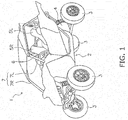
- FIG. 1 is a perspective view of a vehicle 1 according to the present preferred embodiment.
- the vehicle 1 according to the present preferred embodiment is a so-called ROV that is suitable for traveling on rough terrain.
- the vehicle 1 includes a vehicle body 2 and a plurality of wheels 3.
- the vehicle 1 includes four wheels.
- the vehicle 1 includes two front wheels and two rear wheels. It should be noted that the number of wheels is not limited to four and may be greater than four.
- the vehicle body 2 includes a prime mover 4 and seats 5L and 5R.
- the prime mover 4 is disposed behind the seats 5R and 5L.
- the seats 5R and 5L are seats disposed in a side-by-side arrangement, and include a right seat 5R and a left seat 5L.
- a steering wheel 6 is disposed in front of the left seat 5L.
- a roll cage 7 is disposed above the seats 5R and 5L.
- the roll cage 7 includes right and left roll cages 7R and 7L.
- the left roll cage 7L is disposed to extend from a position forward of the left seat 5L to a position backward of the left seat 5L through a position above the left seat 5L.
- the right roll cage 7R is disposed to extend from a position forward of the right seat 5R to a position backward of the right seat 5R through a position above the right seat 5R.
- the steering wheel 6 may be disposed in front of the right seat 5R.
- the roll cage 7 may be disposed to extend in a right-and-left direction of the vehicle body 2.
- FIG. 2 is a block diagram showing a drive train and a control system of the vehicle 1.
- the vehicle 1 includes the aforementioned prime mover 4 and a power train 8.
- the prime mover 4 is an engine (internal combustion engine).
- the prime mover 4 includes a throttle valve 41, a fuel injection valve 42 and an ignition unit 43.
- An accelerator operating element 44 is coupled to the throttle valve 41.
- the accelerator operating element 44 is operated by a driver.
- the accelerator operating element 44 may be an accelerator pedal.
- the opening degree of the throttle valve 41 (hereinafter referred to as “throttle opening degree”) is changed in response to operating the accelerator operating element 44. Therefore, the throttle opening degree is changed in accordance with the operating amount of the accelerator operating element 44 (hereinafter referred to as "accelerator operating amount").
- the fuel injection valve 42 injects fuel into the prime mover 4, and the amount of fuel to be injected is set in accordance with the accelerator operating amount or so forth.
- the ignition unit 43 causes spark discharge inside the prime mover 4 at predetermined ignition timing within an engine cycle, whereby mixed gas of fuel and air is ignited.
- FIG. 3 is a schematic diagram of a structure of the power train 8.
- the power train 8 includes a clutch 9, a transmission 10, a propeller shaft 12, a first differential gear 13, a first axle 14, a second differential gear 15 and a second axle 16.
- the clutch 9 is connected to a crankshaft 47 of the prime mover 4.
- the transmission 10 is connected to the clutch 9 and the propeller shaft 12.
- the propeller shaft 12 extends in a vehicle back-and-forth direction.
- the propeller shaft 12 is connected to the first axle 14 through the first differential gear 13.
- the first axle 14 extends in the right-and-left direction and is connected to the right and left wheels 3.
- the propeller shaft 12 is connected to the second axle 16 through the second differential gear 15.
- the second axle 16 extends in the right-and-left direction and is connected to the right and left wheels 3. It should be noted that the first axle 14 may be connected to the front wheels, whereas the second axle 16 may be connected to the rear wheels. Alternatively, the first axle 14 may be connected to the rear wheels, whereas the second axle 16 may be connected to the front wheels.
- the clutch 9 is disposed on a driving force transmission path of the power train 8.
- the clutch 9 is a friction clutch.
- the clutch 9 includes a drive member 91 and a driven member 92.
- the drive member 91 is connected to the crankshaft 47 of the prime mover 4.
- the driven member 92 is connected to the transmission 10.
- the drive member 91 and the driven member 92 are configured to approach to and separate from each other.
- the drive member 91 and the driven member 92 are, for instance, clutch plates. It should be noted that each of the drive member 91 and the driven member 92 may have a different shape from the plate shape. Rotation of the crankshaft 47 of the prime mover 4 is transmitted to the drive member 91. A reduction gear may be provided between the crankshaft 47 and the drive member 91.
- the clutch 9 is settable in a disengaged state, an engaged state and a half-engaged state.
- the disengaged state the drive member 91 and the driven member 92 are separated from each other, whereby a torque is not transmitted therebetween.
- the engaged state the drive member 91 and the driven member 92 are engaged with each other without sliding against each other, whereby a torque is transmitted therebetween.
- the half-engaged state is an intermediate state between the engaged state and the disengaged state. In the half-engaged state, the drive member 91 and the driven member 92 make contact with each other while sliding against each other (slide in contact), whereby part of a torque is transmitted therebetween.
- the transmission 10 is disposed on the driving force transmission path of the power train 8.
- the transmission 10 includes a primary transmission 17 and a subsidiary transmission 18.
- the primary transmission 17 includes a plurality of shift gears.
- the plurality of shift gears are capable of being disposed in a plurality of gear positions.
- the plurality of gear positions include at least one forward gear position, at least one reverse gear position and a neutral position. Additionally, the plurality of shift gears include a plurality of gear positions having different gear ratios.
- the primary transmission 17 includes a shift member 31.
- the shift member 31 may be, for instance, a shift cam, a shift fork or so forth.
- One to be engaged among the plural shift gears can be changed by displacement of the shift member 31, whereby one of the gear positions of the primary transmission 17 is selectable.
- the primary transmission 17 outputs rotation transmitted to an input shaft 11 of the transmission 10 from the clutch 9 after converting the rotation in accordance with the gear ratio and rotational direction corresponding to one selected from the gear positions of the primary transmission 17.
- the subsidiary transmission 18 is connected to the primary transmission 17 through a transmission shaft 19. As show in FIG. 3 , the subsidiary transmission 18 includes high and low gears 18H and 18L that the gear ratios thereof are different from each other. The subsidiary transmission 18 is capable of selecting either the high gear 18H or the low gear 18L as the gear position thereof.
- the subsidiary transmission 18 includes a shift member 32.
- the shift member 32 may be, for instance, a shift cam or a shift fork.
- the gear position of the subsidiary transmission 18 can be selected from the high gear 18H and the low gear 18L by shifting the shift member 32.
- the subsidiary transmission 18 is connected to the propeller shaft 12.
- the subsidiary transmission 18 outputs rotation, transmitted thereto from the primary transmission 17, to the propeller shaft 12 after converting the rotation in accordance with the gear ratio corresponding to one selected from the gear positions of the subsidiary transmission 18.
- the first differential gear 13 transmits the rotation of the propeller shaft 12 to the first axle 14.
- the first axle 14 includes a right axle 14R and a left axle 14L.
- the first differential gear 13 is switched among an unlocked state, a locked state and a neutral state. In the unlocked state, the first differential gear 13 allows difference in rotational velocity between the right axle 14R and the left axle 14L in accordance with difference in load between the right axle 14R and the left axle 14L, and transmits the rotation of the propeller shaft 12 to the right and left axles 14R and 14L.
- the first differential gear 13 restricts difference in rotational velocity between the right wheel 3 and the left wheel 3.
- the first differential gear 13 transmits the rotation of the propeller shaft 12 to the right and left axles 14R and 14L such that the right and left axles 14R and 14L are rotated at the same rotational velocity.
- the right and left axles 14R and 14L are rotated, whereby the right and left wheels 3 are rotated.
- the first differential gear 13 decouples the propeller shaft 12 and the right and left axles 14R and 14L.
- FIG. 4 is a cross-sectional view of the first differential gear 13.
- the first differential gear 13 includes a drive pinion gear 51, a ring gear 52, a differential pinion shaft 53, a differential pinion gear 54, a right side gear 55, a left side gear 56 and a differential case 57.
- the drive pinion gear 51 is coupled to the propeller shaft 12.
- the ring gear 52 is meshed with the drive pinion gear 51.
- the differential pinion shaft 53 is rotated together with the ring gear 52.
- the differential pinion gear 54 is rotated about the rotational center of the right and left axles 14R and 14L together with the differential pinion shaft 53. Additionally, the differential pinion gear 54 is rotated about the axis of the differential pinion shaft 53 with respect to the differential pinion shaft 53.
- the right and left side gears 55 and 56 are meshed with the differential pinion gear 54.
- the differential case 57 accommodates the differential pinion gear 54 and the differential pinion shaft 53.
- the differential case 57 is coupled to the ring gear 52, and is rotated together with the ring gear 52.
- the first differential gear 13 includes a differential lock 58, a right output shaft 59 and a left output shaft 60.
- the right output shaft 59 is coupled to the right axle 14R.
- the left output shaft 60 is coupled to the left axle 14L.
- the differential lock 58 switches the first differential gear 13 between the locked state and the unlocked state.
- the differential lock 58 includes a shift member 61, a first meshing portion 62 and a second meshing portion 63.
- the shift member 61 is provided to be movable with respect to the right output shaft 59 in the axial direction of the right output shaft 59.
- the first meshing portion 62 is provided on the right side gear 55.
- the second meshing portion 63 is provided on the differential case 57.
- the first differential gear 13 is switched among the neutral state, the unlocked state and the locked state in conjunction with movement of the shift member 61 in the axial direction of the right output shaft 59.
- the right output shaft 59 is fixed to the right side gear 55.
- the right and left side gears 55 and 56 are rotatable at rotational velocities different from each other. Accordingly, the first differential gear 13 is set in the unlocked state.
- the first differential gear 13 is set in the neutral state. In the neutral state, the right and left output shafts 59 and 60 are capable of idling with respect to the ring gear 52.
- the second differential gear 15 has a similar configuration to the first differential gear 13.
- the second differential gear 15 transmits rotation of the propeller shaft 12 to right and left axles 16R and 16L.
- the right and left axles 16R and 16L are rotated, whereby the right and left wheels 3 are rotated.
- the second differential gear 15 may not include the differential lock 58. In other words, the second differential gear 15 may be always in the unlocked state.
- the vehicle 1 includes a controller 20.
- the controller 20 includes a computing unit such as a CPU and memories such as an RAM and an ROM.
- the controller 20 is programmed to control the prime mover 4, the clutch 9, the transmission 10 and the front and rear differential gears 13 and 15.
- the vehicle 1 includes a throttle opening degree sensor 45 and a crank sensor 46.
- the throttle opening degree sensor 45 detects the throttle opening degree of the prime mover 4. A signal indicating the throttle opening degree is inputted into the controller 20.
- the crank sensor 46 is a sensor that detects rotation of the crankshaft 47 of the prime mover 4. A signal indicating rotation of the crankshaft 47 is inputted into the controller 20.
- the crank sensor 46 is a magnetic sensor, for instance, and detects rotation of a magnet rotated together with the crankshaft 47.
- the controller 20 may calculate an engine rotational speed from the rotational velocity of the crankshaft 47 detected by the crank sensor 46.
- the engine rotational speed corresponds to an input-side rotational velocity of the clutch 9. Therefore, the crank sensor 46 detects the input-side rotational velocity of the clutch 9.
- the clutch 9 includes a clutch actuator 93.
- the controller 20 controls the clutch actuator 93.
- the clutch actuator 93 makes the drive member 91 and the driven member 92 in the clutch 9 approach to and separate from each other.
- the clutch actuator 93 is configured to strengthen or weaken a pressing force acting between the drive member 91 and the driven member 92, while the drive member 91 and the driven member 92 make contact with each other. Accordingly, the drive member 91 and the driven member 92 make contact by friction with each other, and a torque to be transmitted therebetween increases and reduces.
- the clutch actuator 93 By controlling the clutch actuator 93, the state of the clutch 9 can be changed among the disengaged state, the half-engaged state and the engaged state, and the pressing force acting between the drive member 91 and the driven member 92 can be changed in the half-engaged state.
- the clutch actuator 93 may be an electric actuator.
- the clutch actuator 93 may be a hydraulic actuator.
- the clutch actuator 93 is provided with a clutch actuator sensor 94.
- the clutch actuator sensor 94 detects the position of an actuating element of the clutch actuator 93.
- the position of the actuating element of the clutch actuator 93 corresponds to distance between the drive member 91 and the driven member 92 in the clutch 9.
- the controller 20 drives the clutch actuator 93 based on an output signal from the clutch actuator sensor 94, whereby the pressing force in the clutch 9, in other words, an engaging force is controlled.
- the primary transmission 17 includes a gear shift actuator 33.
- the gear shift actuator 33 actuates the shift member 31, whereby the gear position of the primary transmission 17 is changed.
- the controller 20 executes gear shifting of the primary transmission 17 by controlling the gear shift actuator 33.
- the gear shift actuator 33 may be an electric actuator.
- the gear shift actuator 33 may be a hydraulic actuator.
- the primary transmission 17 is provided with a shift gear position sensor 34.
- the shift gear position sensor 34 detects the gear position of the primary transmission 17.
- An output signal from the shift gear position sensor 34 is inputted into the controller 20.
- the shift gear position sensor 34 may be a sensor that detects the position of the shift member 31.
- the subsidiary transmission 18 includes a high/low shift actuator 35.
- the high/low shift actuator 35 actuates the shift member 32, whereby the gear position of the subsidiary transmission 18 is changed.
- the controller 20 changes the gear position of the subsidiary transmission 18 by controlling the high/low shift actuator 35.
- the high/low shift actuator 35 may be an electric actuator. Alternatively, the high/low shift actuator 35 may be a hydraulic actuator.
- the subsidiary transmission 18 is provided with a high/low gear position sensor 36.
- the high/low gear position sensor 36 detects the gear position of the subsidiary transmission 18.
- An output signal from the high/low gear position sensor 36 is inputted into the controller 20.
- the high/low gear position sensor 36 may be a sensor that detects the position of the shift member 32.
- the power train 8 includes a vehicle velocity sensor 37 that detects the velocity of the vehicle.
- An output signal from the vehicle velocity sensor 37 is inputted into the controller 20.
- the vehicle velocity sensor 37 detects the rotational velocity of the wheels 3.
- the vehicle velocity sensor 37 may be a sensor that detects the rotational velocity of the propeller shaft 12,
- the rotational velocity of the propeller shaft 12 is proportional to that of the wheels 3.
- the rotational velocity of the wheels 3 can be detected by detecting that of the propeller shaft 12.
- Correspondence is established between the rotational velocity of the propeller shaft 12 and the output-side rotational velocity of the clutch 9 based on the shift gear ratio in the transmission 10. Therefore, the vehicle velocity sensor 37 detects the output-side rotational velocity of the clutch 9.
- the vehicle velocity sensor 37 is a magnetic sensor, for instance, and detects the rotation of a magnet rotated together with the propeller shaft 12.
- the controller 20 may calculate the vehicle velocity from the rotational velocity of the propeller shaft 12 detected by the vehicle velocity sensor 37.
- the vehicle velocity sensor 37 may be a type of sensor other than the magnetic sensor.
- the first differential gear 13 includes a differential actuator 38.
- the differential actuator 38 actuates the shift member 61.
- the controller 20 switches the first differential gear 13 among the locked state, the unlocked state and the neutral state by controlling the differential actuator 38.
- the differential actuator 38 may be an electric actuator.
- the differential actuator 38 may be a hydraulic actuator.
- the first differential gear 13 includes a differential position sensor 39.
- the differential position sensor 39 detects the position of the shift member 61.
- the position of the shift member 61 indicates the state of the first differential gear 13.
- An output signal, indicating the position of the shift member 61, is inputted into the controller 20.
- the vehicle 1 includes a drive switch 23, a reverse switch 24 and a neutral switch 25.
- the drive switch 23 is a switch to be operated by the driver in order to select one of the at least one forward gear position of the transmission 10.
- the controller 20 changes the gear position of the transmission 10 into the forward position by controlling the clutch actuator 93 and the gear shift actuator 33.
- the reverse switch 24 is a switch to be operated by the driver in order to select one of the at least one reverse gear position of the transmission 10.
- the controller 20 changes the gear position of the transmission 10 into the reverse position by controlling the clutch actuator 93 and the gear shift actuator 33.
- the neutral switch 25 is a switch to be operated by the driver in order to select a neutral state of the transmission 10.
- the controller 20 changes the gear position of the transmission 10 into the neutral position by controlling the clutch actuator 93 and the gear shift actuator 33.
- the drive switch 23, the reverse switch 24 and the neutral switch 25 may be provided on a shift lever.
- the drive switch 23, the reverse switch 24 and the neutral switch 25 may be switches provided separately from each other.
- the vehicle 1 includes a shift-up switch 21 and a shift-down switch 22.
- the shift-up switch 21 is a switch to be operated by the driver in order to change the gear position (gear stage) of the transmission 10 to a high speed side by one stage.
- the shift-down switch 22 is a switch to be operated by the driver in order to change the gear position (gear stage) of the transmission 10 to a low speed side by one stage.
- the shift-up switch 21 is connected to a first operating element 26.
- the shift-down switch 22 is connected to a second operating element 27.
- the first and second operating elements 26 and 27 may be paddles disposed in the surroundings of the steering wheel 6.
- an output signal from the shift-up switch 21 is inputted into the controller 20.
- an output signal from the shift-down switch 22 is inputted into the controller 20.
- the controller 20 executes a gear shift action by driving the clutch actuator 93 and the gear shift actuator 33 in response to inputs from the shift switches 21 and 22, whereby the gear position (gear stage) is changed among a plurality of forward gear positions.
- the vehicle 1 includes a brake switch 28.
- the brake switch 28 is a switch to be operated by the driver in order to actuate a brake device (not shown in the drawings).
- the vehicle 1 is decelerated in conjunction with actuation of the brake device.
- the brake switch 28 is connected to a brake operating element 29.
- the brake operating element 29 may be, for instance, a brake pedal.
- the vehicle 1 includes a high/low gear selecting switch 64.
- the high/low gear selecting switch 64 is a switch to be operated by the driver in order to select the gear position of the subsidiary transmission 18.
- the controller 20 switches the gear position of the subsidiary transmission 18 between the high gear 18H and the low gear 18L by controlling the high/low shift actuator 35 in response to an output signal from the high/low gear selecting switch 64.
- the vehicle 1 includes a differential selecting switch 65.
- the differential selecting switch 65 is a switch to be operated by the driver in order to select the state of the first differential gear 13.
- the controller 20 switches the state of the first differential gear 13 among the locked state, the unlocked state and the neutral state by controlling the differential actuator 38 in response to an output signal from the differential selecting switch 65. It should be noted that the state of the first differential gear 13 may be automatically switched by the controller 20 without being switched by operating the differential selecting switch 65.
- the vehicle 1 is capable of executing moving start in a normal mode and moving start based on moving start control.
- the driver selects one of the gear positions other than the neutral position by operating the shift-up switch 21, the shift-down switch 22, the drive switch 23 or the reverse switch 24. Accordingly, the controller 20 changes the gear position of the transmission 10 by driving the gear shift actuator 33.
- the driver increase the accelerator operating amount by operating the accelerator operating element 44.
- the throttle opening degree increases in response to this operation, the engine rotational speed increases.
- the controller 20 increases the engaging force of the clutch 9 by controlling the clutch actuator 93, whereby the drive member 91 and the driven member 92 approach to each other.
- the controller 20 sets a target engine rotational speed in accordance with the throttle opening degree, and controls the engaging force of the clutch 9 such that the engine rotational speed increases toward the target engine rotational speed. Accordingly, the engaging force between the drive member 91 and the driven member 92 gradually increases, and the clutch 9 transitions from the disengaged state to the engaged state via the half-engaged state.
- the controller 20 executes control of the fuel injection valve 42 (fuel injection control) and control of the ignition unit 43 (ignition control) so as to obtain an engine output in accordance with the throttle opening degree.
- a gear shift command is inputted into the controller 20.
- the controller 20 executes the gear shift action. Specifically, the controller 20 disengages the clutch 9 by controlling the clutch actuator 93. Moreover, the controller 20 changes the gear position of the primary transmission 17 in response to the gear shift command by controlling the gear shift actuator 33. Alternatively, the controller 20 changes the gear position of the subsidiary transmission 18 in response to the gear shift command by controlling the high/low shift actuator 35.
- the controller 20 leads the clutch 9 to the engaged state via the half-engaged state by controlling the clutch actuator 93.
- the controller 20 executes the fuel injection control and the ignition control so as to obtain the engine output in accordance with the throttle opening degree.
- the controller 20 executes automatic shift-down control.
- the shift-down threshold has been preliminarily set and the value thereof depends on the gear positions. More specifically, when the vehicle velocity gets lower than a clutch disengaging threshold that the value thereof depends on the gear stages, the controller 20 changes the clutch 9 into the disengaged state by controlling the clutch actuator 93. Subsequently, when the vehicle velocity gets lower than the shift-down threshold, the controller 20 changes the gear position by controlling the gear shift actuator 33 so as to shift down the gear stage by one stage.
- the controller 20 changes the gear position so as to further shift down the gear stage by one stage. Thereafter, the controller 20 leads the clutch 9 to the engaged state via the half-engaged state by controlling the clutch actuator 93.
- the controller 20 executes the fuel injection control and the ignition control so as to obtain the engine output in accordance with the throttle opening degree.
- the controller 20 disengages the clutch 9. More specifically, when the vehicle velocity gets lower than the clutch disengaging threshold while the lowest one of the plurality of forward gear positions is being selected, the clutch 9 is disengaged. This configuration is similarly true of the at least one reverse gear position. In a configuration that the number of reverse gear positions is only one, the clutch 9 is disengaged when the vehicle velocity gets lower than the clutch disengaging threshold corresponding to the reverse gear position.
- FIG. 6 is a flowchart showing processing in the moving start control to be executed by the controller 20.
- step S1 the controller 20 sets a control mode to the normal mode. In this case, moving start is executed in the aforementioned normal mode.
- step S2 the controller 20 determines whether or not a standby condition has been satisfied.
- the standby condition indicates that predetermined operates have been executed for the aforementioned specific operating elements. Specifically, the standby condition indicates that the first and second operating elements 26 and 27 have been operated, and in addition, the brake operating element 29 has been operated. For example, the standby condition is determined as having been satisfied when the first and second operating elements 26 and 27 have been pulled toward the driver and the brake operating element 29 has been treaded down.
- the standby condition is determined as having been satisfied when the first and second operating elements 26 and 27 have been pulled toward the driver and the brake operating element 29 has been treaded down.
- the standby condition has not been satisfied yet, the normal mode is maintained in step S1.
- the processing proceeds to step S3.
- step S3 the controller 20 determines whether or not either of the following conditions has been satisfied: the high gear 18H has been selected; and the first differential gear 13 has been in the unlocked state.
- step S4 the controller 20 sets the control mode to a moving start standby mode.
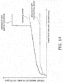
- FIG. 7 is a timing chart showing variation in state of the clutch 9, vehicle speed and so forth in the moving start control.
- the control mode is set to the moving start standby mode.
- the clutch 9 is maintained in the disengaged state. Therefore, even if the driver increases the accelerator operating amount by operating the accelerator operating element 44 in the moving start standby mode, the vehicle 1 does not travel and the vehicle velocity thereof does not increase.
- the driver releases the brake operating element 29 from the operated state thereof while keeping the first and second operating elements 26 and 27 in the operated states.
- the throttle opening degree is changed in accordance with the operating amount of the accelerator operating element 44, whereby the engine rotational speed is changed. Therefore, in the moving start standby mode, the engine rotational speed can be increased when the driver increases the accelerator operating amount by operating the accelerator operating element 44 while the vehicle 1 stands still.
- step S5 of FIG. 6 the controller 20 determines whether or not an execution condition has been satisfied.
- the execution condition is that the predetermined operations have been executed for the aforementioned specific operating elements.
- the execution condition is composed of requirements that the accelerator operating amount is greater than or equal to a predetermined threshold and that the first and second operating elements 26 and 27 are released from the operated states thereof.
- the execution condition is determined as having been satisfied when the driver has fully treaded down the accelerator operating element 44 and has released the first and second operating elements 26 and 27 from the operated states thereof.
- the processing proceeds to step S6.
- step S6 similarly to step S3, the controller 20 determines whether or not either of the following conditions has been satisfied: the high gear 18H has been selected; and the first differential gear 13 has been in the unlocked state.
- the processing proceeds to step S7 when either of the following conditions is determined as having been satisfied in step S6: the high gear 18H has been selected; and the first differential gear 13 has been in the unlocked state.
- step S7 the controller 20 sets the control mode to a moving start execution mode.
- the controller 20 makes the clutch 9 transition from the disengaged state to the engaged state through the half-engaged state. Accordingly, the driving force of the prime mover 4 is transmitted to the wheels 3, whereby the vehicle 1 starts moving.
- step S3 or S6 when the first differential gear 13 is determined as not being in the unlocked state, the processing proceeds to step S8.
- step S3 or S6 when the high gear 18H is determined as not being selected, the processing also proceeds to step S8.
- the phrase "not being in the unlocked state” means that the first differential gear 13 is in a state other than the unlocked state. Therefore, the phrase “not being in the unlocked state” encompasses the locked state. Additionally, the phrase “not being in the unlocked state” also encompasses that it has not been decided yet in which of the locked state and the unlocked state the first differential gear 13 is being set. When it has not been decided yet in which of the locked state and the unlocked state the first differential gear 13 is being set, for instance, the differential gear 13 is not firmly engaged as with when a sleeve for switching the first differential gear 13 is not fitted in a proper state.
- the phrase "the high gear 18H is decided as not being selected” encompasses that the low gear 18L is being selected. Additionally, the phrase “the high gear 18H is determined as not being selected” encompasses that it has not been decided yet which of the high gear 18H and the low gear 18L is being selected.
- the gear position of the subsidiary transmission 18 is transitioning between the high gear 18H and the low gear 18L.
- the transmission 10 may be in the neutral state.
- the gear position of the transmission 10 may be the reverse gear position.
- step S8 the control mode is set to a moving start restriction mode.
- the controller 20 prevents the moving start control. Therefore, in the moving start restriction mode, the controller 20 temporarily prevents moving start of the vehicle 1, and thereafter, executes moving start of the vehicle 1 in the normal mode.
- FIG. 8 is a block diagram showing clutch control and engine control in the moving start execution mode and the moving start restriction mode.
- the controller 20 stores a piece of clutch control information in the moving start execution mode and that in the moving start restriction mode.
- the moving start control may be prevented as described above, but alternatively, it is also possible to change a clutch engaging method in the moving start control.
- These pieces of clutch control information define relations among difference in rotational velocity between the input and output sides in the clutch 9, the throttle opening degree and the engaging torque in the clutch 9.
- the pieces of clutch control information may be expressed in the form of, for instance, a map, a table, a calculation formula or so forth.
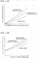
- FIG. 9(A) is a chart showing a relation between difference in rotational velocity and the engaging torque in the clutch 9, which is defined by the pieces of clutch control information.
- the engaging torque in the clutch 9 in the moving start execution mode, the engaging torque in the clutch 9 is increased with increase in difference in rotational velocity.
- the engaging torque in the clutch 9 correlates to an engaging speed of the clutch 9.
- the engaging speed of the clutch 9 is increased with increase in engaging torque of the clutch 9. Therefore, in the moving start execution mode, the engaging speed of the clutch 9 is increased with increase in difference in rotational velocity. Accordingly, the driving force in moving start gets larger in the moving start execution mode than in the moving start restriction mode.
- the engaging torque in the clutch 9 is increased with increase in difference in rotational velocity. It should be noted that at the value of difference in rotational velocity, the engaging torque in the clutch 9 is larger in the moving start execution mode than in the moving start restriction mode. Therefore, at the same value of difference in rotational velocity, the clutch 9 is engaged at a greater engaging speed in the moving start execution mode than in the moving start restriction mode. Accordingly, the driving force in moving start gets larger in the moving start execution mode than in the moving start restriction mode.
- FIG. 9(B) is a chart showing a relation between the throttle opening degree and the engaging torque in the clutch 9, which is defined by the pieces of clutch control information. As shown in FIG. 9(B) , in the moving start execution mode, the engaging torque in the clutch 9 is increased with increase in throttle opening degree. Therefore, in the moving start execution mode, the engaging speed of the clutch 9 is increased with increase in throttle opening degree.
- the engaging torque in the clutch 9 is increased with increase in throttle opening degree. It should be noted that at the same value of the throttle opening degree, the engaging torque in the clutch 9 is larger in the moving start execution mode than in the moving start restriction mode. Therefore, at the same value of the throttle opening degree, the clutch 9 is engaged at a greater engaging speed in the moving start execution mode than in the moving start restriction mode.
- the controller 20 stores a piece of engine control information in the moving start execution mode and that in the moving start restriction mode.
- These pieces of engine control information are pieces of information that define a relation between the throttle opening degree and the target engine rotational speed.
- the pieces of engine control information may be expressed in the form of, for instance, a map, a table, a calculation formula or so forth.
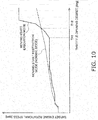
- FIG. 10 is a chart showing the relation between the throttle opening degree and the target engine rotational speed, which is defined by the pieces of engine control information.
- the target engine rotational speed is increased with increase in throttle opening degree.
- the target engine rotational speed is abruptly increased when the throttle opening degree is greater than or equal to a predetermined first opening degree TH1.
- the target engine rotational speed in the moving start execution mode gets greater than that in the moving start restriction mode. Therefore, when the accelerator operating element 44 is greatly operated, the engine rotational speed in the moving start execution mode gets greater than that in the moving start restriction mode. Accordingly, the driving force in moving start gets larger in the moving start execution mode than in the moving start restriction mode.
- the controller 20 starts moving the vehicle 1 in the normal mode. Therefore, similarly in the normal mode, the engaging speed of the clutch 9 is controlled based on the aforementioned piece of clutch control information in the moving start restriction mode. Additionally, similarly in the normal mode, the engine rotational speed is controlled based on the piece of engine control information in the moving start restriction mode.
- the controller 20 controls the engaging force of the clutch 9 in moving start in accordance with which of the locked state and the unlocked state is being selected by the first differential gear 13. Specifically, when the first differential gear 13 is in the locked state, the controller 20 executes moving start of the vehicle 1 in the moving start restriction mode even if the execution condition of the moving start control is satisfied. Likewise, when it has not been decided yet in which of the locked state and the unlocked state the first differential gear 13 is being set, the controller 20 executes moving start of the vehicle 1 in the moving start restriction mode. Accordingly, in accordance with which of the locked state and the unlocked state is being selected by the first differential gear 13, it is possible to execute the moving start control in a mode suitable for a situation of the vehicle 1.
- the controller 20 controls the engaging force of the clutch 9 in accordance with which of the high gear 18H and the low gear 18L is being selected in the transmission 10. Specifically, when the gear position of the subsidiary transmission 18 is the low gear 18L, the controller 20 executes moving start of the vehicle 1 in the moving start restriction mode even if the execution condition of the moving start control is satisfied. Additionally, when it has not been decided yet which of the high gear 18H and the low gear 18L is being selected, the controller 20 also executes moving start of the vehicle 1 in the moving start restriction mode. Accordingly, in accordance with which of the low gear 18L and the high gear 18H is being selected, it is possible to execute the moving start control in a mode suitable for a situation of the vehicle 1.
- the vehicle 1 is not limited to an ROV, and may be another type of vehicle such as an ATV (All Terrain Vehicle).
- ATV All Terrain Vehicle
- the configuration of the vehicle 1 may not be limited to that described above, and may be changed.
- at least one rear seat may be disposed behind the aforementioned right and left seats 5R and 5L.
- the prime mover 4 may be another type of device such as an electric motor.
- the aforementioned engine rotational speed may be an output rotational speed of the prime mover 4.
- a target output rotational speed of the prime mover 4 may be determined in accordance with the accelerator operating amount.
- the driving force in the moving start control may be reduced without preventing the moving start control and then enabling the normal mode.
- the engaging torque in the clutch 9 may be smaller than that in the moving start execution mode but may be larger than that in the normal mode.
- the target engine rotational speed at the second opening degree TH2 or greater may be less than that in the moving start execution mode but may be greater than that in the normal mode.
- the engaging torque in the clutch 9 may be smaller than that in the moving start execution mode and that in the normal mode.
- the target engine rotational speed may be less than that in the moving start execution mode and that in the normal mode.
Landscapes
- Engineering & Computer Science (AREA)
- Mechanical Engineering (AREA)
- Transportation (AREA)
- Chemical & Material Sciences (AREA)
- Combustion & Propulsion (AREA)
- Automation & Control Theory (AREA)
- Aviation & Aerospace Engineering (AREA)
- Control Of Transmission Device (AREA)
- General Engineering & Computer Science (AREA)
- Retarders (AREA)
- Arrangement And Mounting Of Devices That Control Transmission Of Motive Force (AREA)
- Hydraulic Clutches, Magnetic Clutches, Fluid Clutches, And Fluid Joints (AREA)
- Body Structure For Vehicles (AREA)
- Control Of Driving Devices And Active Controlling Of Vehicle (AREA)
- Motor Power Transmission Devices (AREA)
Abstract
Description
- The present invention relates to a vehicle and a control method thereof.
- Vehicles such as a recreational off-highway vehicle (ROV) have chances of traveling on unpaved roads of sandy terrain, rough terrain and so forth. In such a situation, wheels are likely to slip. However, when a vehicle includes a clutch that transmits/blocks transmission of a driving force, moving start control for getting out of a slip state is enabled by controlling the clutch.
- For example, a leisure vehicle described in Japan Laid-open Patent Application Publication No.
2006-329118 2006-329118 - On the other hand, Japan Laid-open Patent Application Publication No.
2009-078713 2009-078713 - Incidentally, a differential gear is generally switchable between a locked state and an unlocked state in a vehicle that travels on unpaved roads, and a driver or rider generally executes switching between these states in accordance with a traveling condition. For example, there is a situation that in occurrence of slippage on a bad conditioned road, a vehicle gets out of the bad conditioned road by eliminating spinning of right and left wheels with use of a differential lock. Alternatively, a vehicle can quickly get out of a bad conditioned road with use of moving start control to increase a driving force in moving start of the vehicle.
- However, the following drawback emerges in combinational use of the moving start control and switching between the locked state and the unlocked state by the differential lock.
- First, wheels are unlikely to spin in the locked state of the differential gear. Because of this, when the vehicle travels at a high velocity by the moving start control in the locked state of the differential gear, a strong reaction (kickback) inevitably acts on the vehicle from the road surface. On the other hand, when the differential lock is not firmly engaged, the locked state is possibly switched into the unlocked-state or vice versa during moving start of the vehicle. This is not preferable as a behavior during the moving start control.
- Second, there is difference in performance required for moving start of a vehicle between two situations: the vehicle gets out of a bad conditioned road; and the vehicle accelerates fast on flat terrain. For example, a strong driving force is instantaneously required in the situation that the vehicle gets out of a bad conditioned road in comparison with the situation that the vehicle accelerates fast on flat terrain.
- On the other hand, in some vehicles, a high gear and a low gear are selectable. In such a vehicle, there is large difference in gear ratio between the high gear and the low gear. Due to this, when the moving start control is executed while the low gear is being selected, for instance, an excessive driving force can be generated. In this case, even when such a large driving force is obtained by the moving start control, a drawback emerges that the vehicle cannot run fast because wheels dig the earth and sand too much.
- It is an object of the present invention to execute moving start control suitable for a situation of a vehicle in accordance with which one of a locked state and an unlocked state is being selected by a differential gear. It is another object of the present invention to execute moving start control suitable for a situation of a vehicle in accordance with which of a low gear and a high gear is being selected.
- A vehicle according to a first aspect includes a prime mover, a pair of right and left wheels, a propeller shaft, an axle, a differential gear, a differential lock, a clutch and a controller. The propeller shaft is configured to transmit a driving force of the prime mover. The axle is coupled to the pair of right and left wheels. The differential gear is configured to transmit rotation of the propeller shaft to the axle. The differential lock is configured to switch the differential gear between a locked state and an unlocked state. The clutch is provided on a power transmission path between the prime mover and the pair of right and left wheels. The controller is configured to control an engaging force or is configured to change an engine speed of the clutch in moving start of the vehicle in accordance with which of the locked state and the unlocked state is being selected by the differential gear, and the controller is configured to execute a moving start control to increase the driving force in moving start of the vehicle more than usual by controlling an engaging force of the clutch.
- A vehicle according to a second aspect includes a prime mover, a pair of right and left wheels, a transmission, a clutch and a controller. The clutch is provided on a power transmission path between the prime mover and the pair of right and left wheels. The transmission is configured to include at least a high gear and a low gear, and transmits a driving force of the prime mover to the pair of right and left wheels. The controller is configured to execute a moving start control to increase the driving force in moving start of the vehicle more than usual by controlling an engaging force of the clutch. The controller is configured to control the engaging force or is configured to change an engine speed of the clutch in moving start of the vehicle in accordance with which of the high gear and the low gear is being selected in the transmission.
- A control method according to a third aspect is a method of controlling a vehicle. The vehicle includes a differential gear that transmits rotation of a propeller shaft to an axle coupled to a pair of right and left wheels. The propeller shaft herein transmits a driving force of a prime mover. The control method includes the following steps. In the first step, it is determined which of a locked state and an unlocked state is being selected by the differential gear. In the second step, an engaging force of a clutch in moving start of the vehicle in accordance with which of the locked state and the unlocked state is being selected. The clutch is herein provided on a power transmission path between the prime mover and the pair of right and left wheels.
- A control method according to a fourth aspect is a method of controlling a vehicle. The vehicle includes a transmission that includes at least a high gear and a low gear and transmits a driving force of a prime mover to a pair of right and left wheels. The control method includes the following steps. In the first step, it is determined which of the high gear and the low gear is being selected in the transmission. In the second step, a moving start control is executed to increase the driving force in moving start of the vehicle more than usual by controlling an engaging force of a clutch. The clutch is herein provided on a power transmission path between the prime mover and the pair of right and left wheels. In the third step, the engaging force of the clutch in moving start of the vehicle is controlled in accordance with which of the high gear and the low gear is being selected.
-
FIG. 1 is a perspective view of a vehicle according to a preferred embodiment. -
FIG. 2 is a block diagram showing a drive train and a control system of the vehicle. -
FIG. 3 is a schematic diagram of a configuration of a power train of the vehicle. -
FIG. 4 is a cross-sectional view of a differential gear. -
FIG. 5 is diagram showing an action of the differential gear. -
FIG. 6 is a flowchart showing processing in moving start control. -
FIG. 7 is a timing chart showing variation in clutch state, throttle opening degree and so forth in the moving start control. -
FIG. 8 is a block diagram showing clutch control and engine control in the moving start control. -
FIG. 9 is a chart showing the clutch control in the moving start control. -
FIG. 10 is a chart showing the engine control in the moving start control. -
FIG. 11 is a chart showing clutch control in moving start control according to a modification. -
FIG. 12 is a chart showing engine control in moving start control according to another modification. -
FIG. 13 is a chart showing clutch control in moving start control according to yet another modification. -
FIG. 14 is a chart showing engine control in moving start control according to further yet another modification. - A vehicle according to a preferred embodiment will be hereinafter explained in detail with reference to attached drawings.
FIG. 1 is a perspective view of avehicle 1 according to the present preferred embodiment. Thevehicle 1 according to the present preferred embodiment is a so-called ROV that is suitable for traveling on rough terrain. - As shown in
FIG. 1 , thevehicle 1 includes avehicle body 2 and a plurality ofwheels 3. Thevehicle 1 includes four wheels. Detailedly, thevehicle 1 includes two front wheels and two rear wheels. It should be noted that the number of wheels is not limited to four and may be greater than four. Thevehicle body 2 includes aprime mover 4 andseats prime mover 4 is disposed behind theseats - The
seats right seat 5R and aleft seat 5L. Asteering wheel 6 is disposed in front of theleft seat 5L. Aroll cage 7 is disposed above theseats roll cage 7 includes right and leftroll cages left roll cage 7L is disposed to extend from a position forward of theleft seat 5L to a position backward of theleft seat 5L through a position above theleft seat 5L. Theright roll cage 7R is disposed to extend from a position forward of theright seat 5R to a position backward of theright seat 5R through a position above theright seat 5R. - It should be noted that the
steering wheel 6 may be disposed in front of theright seat 5R. Theroll cage 7 may be disposed to extend in a right-and-left direction of thevehicle body 2. -
FIG. 2 is a block diagram showing a drive train and a control system of thevehicle 1. As shown inFIG. 2 , thevehicle 1 includes the aforementionedprime mover 4 and apower train 8. In the present preferred embodiment, theprime mover 4 is an engine (internal combustion engine). - The
prime mover 4 includes athrottle valve 41, afuel injection valve 42 and anignition unit 43. Anaccelerator operating element 44 is coupled to thethrottle valve 41. Theaccelerator operating element 44 is operated by a driver. Theaccelerator operating element 44 may be an accelerator pedal. The opening degree of the throttle valve 41 (hereinafter referred to as "throttle opening degree") is changed in response to operating theaccelerator operating element 44. Therefore, the throttle opening degree is changed in accordance with the operating amount of the accelerator operating element 44 (hereinafter referred to as "accelerator operating amount"). - The
fuel injection valve 42 injects fuel into theprime mover 4, and the amount of fuel to be injected is set in accordance with the accelerator operating amount or so forth. Theignition unit 43 causes spark discharge inside theprime mover 4 at predetermined ignition timing within an engine cycle, whereby mixed gas of fuel and air is ignited. - The
power train 8 transmits a driving force from theprime mover 4 to thewheels 3.FIG. 3 is a schematic diagram of a structure of thepower train 8. As shown inFIG. 3 , thepower train 8 includes a clutch 9, atransmission 10, apropeller shaft 12, a firstdifferential gear 13, afirst axle 14, a seconddifferential gear 15 and asecond axle 16. - The
clutch 9 is connected to acrankshaft 47 of theprime mover 4. Thetransmission 10 is connected to theclutch 9 and thepropeller shaft 12. Thepropeller shaft 12 extends in a vehicle back-and-forth direction. Thepropeller shaft 12 is connected to thefirst axle 14 through the firstdifferential gear 13. Thefirst axle 14 extends in the right-and-left direction and is connected to the right and leftwheels 3. Additionally, thepropeller shaft 12 is connected to thesecond axle 16 through the seconddifferential gear 15. Thesecond axle 16 extends in the right-and-left direction and is connected to the right and leftwheels 3. It should be noted that thefirst axle 14 may be connected to the front wheels, whereas thesecond axle 16 may be connected to the rear wheels. Alternatively, thefirst axle 14 may be connected to the rear wheels, whereas thesecond axle 16 may be connected to the front wheels. - The
clutch 9 is disposed on a driving force transmission path of thepower train 8. Theclutch 9 is a friction clutch. As shown inFIG. 2 , theclutch 9 includes adrive member 91 and a drivenmember 92. Thedrive member 91 is connected to thecrankshaft 47 of theprime mover 4. The drivenmember 92 is connected to thetransmission 10. - The
drive member 91 and the drivenmember 92 are configured to approach to and separate from each other. Thedrive member 91 and the drivenmember 92 are, for instance, clutch plates. It should be noted that each of thedrive member 91 and the drivenmember 92 may have a different shape from the plate shape. Rotation of thecrankshaft 47 of theprime mover 4 is transmitted to thedrive member 91. A reduction gear may be provided between thecrankshaft 47 and thedrive member 91. - The
clutch 9 is settable in a disengaged state, an engaged state and a half-engaged state. In the disengaged state, thedrive member 91 and the drivenmember 92 are separated from each other, whereby a torque is not transmitted therebetween. In the engaged state, thedrive member 91 and the drivenmember 92 are engaged with each other without sliding against each other, whereby a torque is transmitted therebetween. The half-engaged state is an intermediate state between the engaged state and the disengaged state. In the half-engaged state, thedrive member 91 and the drivenmember 92 make contact with each other while sliding against each other (slide in contact), whereby part of a torque is transmitted therebetween. - The
transmission 10 is disposed on the driving force transmission path of thepower train 8. Thetransmission 10 includes aprimary transmission 17 and asubsidiary transmission 18. Theprimary transmission 17 includes a plurality of shift gears. The plurality of shift gears are capable of being disposed in a plurality of gear positions. The plurality of gear positions include at least one forward gear position, at least one reverse gear position and a neutral position. Additionally, the plurality of shift gears include a plurality of gear positions having different gear ratios. - The
primary transmission 17 includes ashift member 31. Theshift member 31 may be, for instance, a shift cam, a shift fork or so forth. One to be engaged among the plural shift gears can be changed by displacement of theshift member 31, whereby one of the gear positions of theprimary transmission 17 is selectable. Theprimary transmission 17 outputs rotation transmitted to aninput shaft 11 of thetransmission 10 from the clutch 9 after converting the rotation in accordance with the gear ratio and rotational direction corresponding to one selected from the gear positions of theprimary transmission 17. - The
subsidiary transmission 18 is connected to theprimary transmission 17 through atransmission shaft 19. As show inFIG. 3 , thesubsidiary transmission 18 includes high andlow gears subsidiary transmission 18 is capable of selecting either thehigh gear 18H or thelow gear 18L as the gear position thereof. - As shown in
FIG. 2 , thesubsidiary transmission 18 includes ashift member 32. Theshift member 32 may be, for instance, a shift cam or a shift fork. The gear position of thesubsidiary transmission 18 can be selected from thehigh gear 18H and thelow gear 18L by shifting theshift member 32. Thesubsidiary transmission 18 is connected to thepropeller shaft 12. Thesubsidiary transmission 18 outputs rotation, transmitted thereto from theprimary transmission 17, to thepropeller shaft 12 after converting the rotation in accordance with the gear ratio corresponding to one selected from the gear positions of thesubsidiary transmission 18. - The first
differential gear 13 transmits the rotation of thepropeller shaft 12 to thefirst axle 14. As shown inFIG. 3 , thefirst axle 14 includes aright axle 14R and aleft axle 14L. The firstdifferential gear 13 is switched among an unlocked state, a locked state and a neutral state. In the unlocked state, the firstdifferential gear 13 allows difference in rotational velocity between theright axle 14R and theleft axle 14L in accordance with difference in load between theright axle 14R and theleft axle 14L, and transmits the rotation of thepropeller shaft 12 to the right and leftaxles - In the locked state, the first
differential gear 13 restricts difference in rotational velocity between theright wheel 3 and theleft wheel 3. In short, in the locked state, the firstdifferential gear 13 transmits the rotation of thepropeller shaft 12 to the right and leftaxles axles axles wheels 3 are rotated. In the neutral state, the firstdifferential gear 13 decouples thepropeller shaft 12 and the right and leftaxles differential gear 13, the rotation of thepropeller shaft 12 is not transmitted to the right and leftaxles axles propeller shaft 12. -
FIG. 4 is a cross-sectional view of the firstdifferential gear 13. As shown inFIG. 4 , the firstdifferential gear 13 includes adrive pinion gear 51, aring gear 52, adifferential pinion shaft 53, adifferential pinion gear 54, aright side gear 55, aleft side gear 56 and adifferential case 57. - The
drive pinion gear 51 is coupled to thepropeller shaft 12. Thering gear 52 is meshed with thedrive pinion gear 51. Thedifferential pinion shaft 53 is rotated together with thering gear 52. Thedifferential pinion gear 54 is rotated about the rotational center of the right and leftaxles differential pinion shaft 53. Additionally, thedifferential pinion gear 54 is rotated about the axis of thedifferential pinion shaft 53 with respect to thedifferential pinion shaft 53. The right and left side gears 55 and 56 are meshed with thedifferential pinion gear 54. Thedifferential case 57 accommodates thedifferential pinion gear 54 and thedifferential pinion shaft 53. Thedifferential case 57 is coupled to thering gear 52, and is rotated together with thering gear 52. - The first
differential gear 13 includes adifferential lock 58, aright output shaft 59 and aleft output shaft 60. Theright output shaft 59 is coupled to theright axle 14R. Theleft output shaft 60 is coupled to theleft axle 14L. Thedifferential lock 58 switches the firstdifferential gear 13 between the locked state and the unlocked state. Thedifferential lock 58 includes ashift member 61, afirst meshing portion 62 and asecond meshing portion 63. - The
shift member 61 is provided to be movable with respect to theright output shaft 59 in the axial direction of theright output shaft 59. Thefirst meshing portion 62 is provided on theright side gear 55. Thesecond meshing portion 63 is provided on thedifferential case 57. The firstdifferential gear 13 is switched among the neutral state, the unlocked state and the locked state in conjunction with movement of theshift member 61 in the axial direction of theright output shaft 59. - As shown in
FIG. 5(A) , when theshift member 61 is meshed with thefirst meshing portion 62, theright output shaft 59 is fixed to theright side gear 55. It should be noted that in conjunction with rotation of thedifferential pinion gear 54 about the axis of thedifferential pinion shaft 53, the right and left side gears 55 and 56 are rotatable at rotational velocities different from each other. Accordingly, the firstdifferential gear 13 is set in the unlocked state. - As shown in
FIG. 5(B) , when theshift member 61 is meshed with the first andsecond meshing parts differential case 57. Accordingly, relative rotation of the right and left side gears 55 and 56 is restricted, whereby the firstdifferential gear 13 is set in the locked state. - It should be noted that as shown in
FIG. 4 , when theshift member 61 is not meshed with both thefirst meshing portion 62 and thesecond meshing portion 63, theright output shaft 59 becomes rotatable with respect to theright side gear 55, and theleft output shaft 60 becomes rotatable with respect to theleft side gear 56. Accordingly, the firstdifferential gear 13 is set in the neutral state. In the neutral state, the right and leftoutput shafts ring gear 52. - The second
differential gear 15 has a similar configuration to the firstdifferential gear 13. The seconddifferential gear 15 transmits rotation of thepropeller shaft 12 to right and leftaxles axles wheels 3 are rotated. It should be noted that the seconddifferential gear 15 may not include thedifferential lock 58. In other words, the seconddifferential gear 15 may be always in the unlocked state. - As shown in
FIG. 2 , thevehicle 1 includes acontroller 20. Thecontroller 20 includes a computing unit such as a CPU and memories such as an RAM and an ROM. Thecontroller 20 is programmed to control theprime mover 4, theclutch 9, thetransmission 10 and the front and rear differential gears 13 and 15. - The
vehicle 1 includes a throttleopening degree sensor 45 and acrank sensor 46. The throttleopening degree sensor 45 detects the throttle opening degree of theprime mover 4. A signal indicating the throttle opening degree is inputted into thecontroller 20. Thecrank sensor 46 is a sensor that detects rotation of thecrankshaft 47 of theprime mover 4. A signal indicating rotation of thecrankshaft 47 is inputted into thecontroller 20. - The
crank sensor 46 is a magnetic sensor, for instance, and detects rotation of a magnet rotated together with thecrankshaft 47. Thecontroller 20 may calculate an engine rotational speed from the rotational velocity of thecrankshaft 47 detected by thecrank sensor 46. The engine rotational speed corresponds to an input-side rotational velocity of theclutch 9. Therefore, thecrank sensor 46 detects the input-side rotational velocity of theclutch 9. - The
clutch 9 includes aclutch actuator 93. Thecontroller 20 controls theclutch actuator 93. Theclutch actuator 93 makes thedrive member 91 and the drivenmember 92 in the clutch 9 approach to and separate from each other. Theclutch actuator 93 is configured to strengthen or weaken a pressing force acting between thedrive member 91 and the drivenmember 92, while thedrive member 91 and the drivenmember 92 make contact with each other. Accordingly, thedrive member 91 and the drivenmember 92 make contact by friction with each other, and a torque to be transmitted therebetween increases and reduces. - By controlling the
clutch actuator 93, the state of the clutch 9 can be changed among the disengaged state, the half-engaged state and the engaged state, and the pressing force acting between thedrive member 91 and the drivenmember 92 can be changed in the half-engaged state. Theclutch actuator 93 may be an electric actuator. Alternatively, theclutch actuator 93 may be a hydraulic actuator. - The
clutch actuator 93 is provided with aclutch actuator sensor 94. Theclutch actuator sensor 94 detects the position of an actuating element of theclutch actuator 93. The position of the actuating element of theclutch actuator 93 corresponds to distance between thedrive member 91 and the drivenmember 92 in theclutch 9. When thedrive member 91 and the drivenmember 92 make contact with each other, the distance corresponds to the pressing force acting between thedrive member 91 and the drivenmember 92. Thecontroller 20 drives theclutch actuator 93 based on an output signal from theclutch actuator sensor 94, whereby the pressing force in theclutch 9, in other words, an engaging force is controlled. - The
primary transmission 17 includes agear shift actuator 33. Thegear shift actuator 33 actuates theshift member 31, whereby the gear position of theprimary transmission 17 is changed. Thecontroller 20 executes gear shifting of theprimary transmission 17 by controlling thegear shift actuator 33. Thegear shift actuator 33 may be an electric actuator. Alternatively, thegear shift actuator 33 may be a hydraulic actuator. - The
primary transmission 17 is provided with a shiftgear position sensor 34. The shiftgear position sensor 34 detects the gear position of theprimary transmission 17. An output signal from the shiftgear position sensor 34 is inputted into thecontroller 20. The shiftgear position sensor 34 may be a sensor that detects the position of theshift member 31. - The
subsidiary transmission 18 includes a high/low shift actuator 35. The high/low shift actuator 35 actuates theshift member 32, whereby the gear position of thesubsidiary transmission 18 is changed. Thecontroller 20 changes the gear position of thesubsidiary transmission 18 by controlling the high/low shift actuator 35. The high/low shift actuator 35 may be an electric actuator. Alternatively, the high/low shift actuator 35 may be a hydraulic actuator. - The
subsidiary transmission 18 is provided with a high/lowgear position sensor 36. The high/lowgear position sensor 36 detects the gear position of thesubsidiary transmission 18. An output signal from the high/lowgear position sensor 36 is inputted into thecontroller 20. The high/lowgear position sensor 36 may be a sensor that detects the position of theshift member 32. - The
power train 8 includes avehicle velocity sensor 37 that detects the velocity of the vehicle. An output signal from thevehicle velocity sensor 37 is inputted into thecontroller 20. Thevehicle velocity sensor 37 detects the rotational velocity of thewheels 3. For example, thevehicle velocity sensor 37 may be a sensor that detects the rotational velocity of thepropeller shaft 12, The rotational velocity of thepropeller shaft 12 is proportional to that of thewheels 3. Hence, the rotational velocity of thewheels 3 can be detected by detecting that of thepropeller shaft 12. Correspondence is established between the rotational velocity of thepropeller shaft 12 and the output-side rotational velocity of the clutch 9 based on the shift gear ratio in thetransmission 10. Therefore, thevehicle velocity sensor 37 detects the output-side rotational velocity of theclutch 9. - The
vehicle velocity sensor 37 is a magnetic sensor, for instance, and detects the rotation of a magnet rotated together with thepropeller shaft 12. Thecontroller 20 may calculate the vehicle velocity from the rotational velocity of thepropeller shaft 12 detected by thevehicle velocity sensor 37. Alternatively, thevehicle velocity sensor 37 may be a type of sensor other than the magnetic sensor. - The first
differential gear 13 includes adifferential actuator 38. Thedifferential actuator 38 actuates theshift member 61. Thecontroller 20 switches the firstdifferential gear 13 among the locked state, the unlocked state and the neutral state by controlling thedifferential actuator 38. Thedifferential actuator 38 may be an electric actuator. Alternatively, thedifferential actuator 38 may be a hydraulic actuator. - The first
differential gear 13 includes adifferential position sensor 39. Thedifferential position sensor 39 detects the position of theshift member 61. The position of theshift member 61 indicates the state of the firstdifferential gear 13. An output signal, indicating the position of theshift member 61, is inputted into thecontroller 20. - As shown in
FIG. 2 , thevehicle 1 includes adrive switch 23, areverse switch 24 and aneutral switch 25. Thedrive switch 23 is a switch to be operated by the driver in order to select one of the at least one forward gear position of thetransmission 10. When thedrive switch 23 is operated, thecontroller 20 changes the gear position of thetransmission 10 into the forward position by controlling theclutch actuator 93 and thegear shift actuator 33. - The
reverse switch 24 is a switch to be operated by the driver in order to select one of the at least one reverse gear position of thetransmission 10. When thereverse switch 24 is operated, thecontroller 20 changes the gear position of thetransmission 10 into the reverse position by controlling theclutch actuator 93 and thegear shift actuator 33. - The
neutral switch 25 is a switch to be operated by the driver in order to select a neutral state of thetransmission 10. When theneutral switch 25 is operated, thecontroller 20 changes the gear position of thetransmission 10 into the neutral position by controlling theclutch actuator 93 and thegear shift actuator 33. - It should be noted that the
drive switch 23, thereverse switch 24 and theneutral switch 25 may be provided on a shift lever. Alternatively, thedrive switch 23, thereverse switch 24 and theneutral switch 25 may be switches provided separately from each other. - The
vehicle 1 includes a shift-upswitch 21 and a shift-down switch 22. The shift-upswitch 21 is a switch to be operated by the driver in order to change the gear position (gear stage) of thetransmission 10 to a high speed side by one stage. The shift-down switch 22 is a switch to be operated by the driver in order to change the gear position (gear stage) of thetransmission 10 to a low speed side by one stage. - The shift-up
switch 21 is connected to afirst operating element 26. The shift-down switch 22 is connected to asecond operating element 27. The first andsecond operating elements steering wheel 6. When thefirst operating element 26 is operated, an output signal from the shift-upswitch 21 is inputted into thecontroller 20. When thesecond operating element 27 is operated, an output signal from the shift-down switch 22 is inputted into thecontroller 20. - The
controller 20 executes a gear shift action by driving theclutch actuator 93 and thegear shift actuator 33 in response to inputs from the shift switches 21 and 22, whereby the gear position (gear stage) is changed among a plurality of forward gear positions. - The
vehicle 1 includes abrake switch 28. Thebrake switch 28 is a switch to be operated by the driver in order to actuate a brake device (not shown in the drawings). Thevehicle 1 is decelerated in conjunction with actuation of the brake device. Thebrake switch 28 is connected to abrake operating element 29. Thebrake operating element 29 may be, for instance, a brake pedal. - The
vehicle 1 includes a high/lowgear selecting switch 64. The high/lowgear selecting switch 64 is a switch to be operated by the driver in order to select the gear position of thesubsidiary transmission 18. Thecontroller 20 switches the gear position of thesubsidiary transmission 18 between thehigh gear 18H and thelow gear 18L by controlling the high/low shift actuator 35 in response to an output signal from the high/lowgear selecting switch 64. - The
vehicle 1 includes a differential selectingswitch 65. The differential selectingswitch 65 is a switch to be operated by the driver in order to select the state of the firstdifferential gear 13. Thecontroller 20 switches the state of the firstdifferential gear 13 among the locked state, the unlocked state and the neutral state by controlling thedifferential actuator 38 in response to an output signal from the differential selectingswitch 65. It should be noted that the state of the firstdifferential gear 13 may be automatically switched by thecontroller 20 without being switched by operating the differential selectingswitch 65. - Next, control in moving start of the
vehicle 1 will be explained. In the present preferred embodiment, thevehicle 1 is capable of executing moving start in a normal mode and moving start based on moving start control. - In the normal mode, the driver selects one of the gear positions other than the neutral position by operating the shift-up
switch 21, the shift-down switch 22, thedrive switch 23 or thereverse switch 24. Accordingly, thecontroller 20 changes the gear position of thetransmission 10 by driving thegear shift actuator 33. - Moreover, the driver increase the accelerator operating amount by operating the
accelerator operating element 44. When the throttle opening degree increases in response to this operation, the engine rotational speed increases. With increase in engine rotational speed, thecontroller 20 increases the engaging force of the clutch 9 by controlling theclutch actuator 93, whereby thedrive member 91 and the drivenmember 92 approach to each other. - The
controller 20 sets a target engine rotational speed in accordance with the throttle opening degree, and controls the engaging force of the clutch 9 such that the engine rotational speed increases toward the target engine rotational speed. Accordingly, the engaging force between thedrive member 91 and the drivenmember 92 gradually increases, and the clutch 9 transitions from the disengaged state to the engaged state via the half-engaged state. - In this way, a torque generated by the
prime mover 4 is transmitted to thetransmission 10 through theclutch 9. Moreover, rotation changed in speed in thetransmission 10 is transmitted to thewheels 3, whereby thevehicle 1 is moved. After the clutch 9 transitions to the engaged state, thecontroller 20 executes control of the fuel injection valve 42 (fuel injection control) and control of the ignition unit 43 (ignition control) so as to obtain an engine output in accordance with the throttle opening degree. - When the driver operates the shift-up
switch 21, the shift-down switch 22 or the high/lowgear selecting switch 64 during traveling of thevehicle 1, a gear shift command is inputted into thecontroller 20. In response to this, thecontroller 20 executes the gear shift action. Specifically, thecontroller 20 disengages the clutch 9 by controlling theclutch actuator 93. Moreover, thecontroller 20 changes the gear position of theprimary transmission 17 in response to the gear shift command by controlling thegear shift actuator 33. Alternatively, thecontroller 20 changes the gear position of thesubsidiary transmission 18 in response to the gear shift command by controlling the high/low shift actuator 35. - Thereafter, the
controller 20 leads the clutch 9 to the engaged state via the half-engaged state by controlling theclutch actuator 93. When the clutch 9 becomes the engaged state and the gear shift action is completed, thecontroller 20 executes the fuel injection control and the ignition control so as to obtain the engine output in accordance with the throttle opening degree. - When the vehicle velocity gets lower than a shift-down threshold in the engaged state of the clutch 9, the
controller 20 executes automatic shift-down control. Here, the shift-down threshold has been preliminarily set and the value thereof depends on the gear positions. More specifically, when the vehicle velocity gets lower than a clutch disengaging threshold that the value thereof depends on the gear stages, thecontroller 20 changes the clutch 9 into the disengaged state by controlling theclutch actuator 93. Subsequently, when the vehicle velocity gets lower than the shift-down threshold, thecontroller 20 changes the gear position by controlling thegear shift actuator 33 so as to shift down the gear stage by one stage. When the vehicle velocity further gets lower than the shift-down threshold that the value thereof corresponds to the gear stage obtained after shifting down, thecontroller 20 changes the gear position so as to further shift down the gear stage by one stage. Thereafter, thecontroller 20 leads the clutch 9 to the engaged state via the half-engaged state by controlling theclutch actuator 93. When the clutch 9 becomes the engaged state and the gear shift action is completed, thecontroller 20 executes the fuel injection control and the ignition control so as to obtain the engine output in accordance with the throttle opening degree. - When the gear stage becomes the lowest stage and the vehicle velocity gets lower than the clutch disengaging threshold corresponding to the lowest stage, the
controller 20 disengages theclutch 9. More specifically, when the vehicle velocity gets lower than the clutch disengaging threshold while the lowest one of the plurality of forward gear positions is being selected, theclutch 9 is disengaged. This configuration is similarly true of the at least one reverse gear position. In a configuration that the number of reverse gear positions is only one, theclutch 9 is disengaged when the vehicle velocity gets lower than the clutch disengaging threshold corresponding to the reverse gear position. - Next, the moving start control will be explained. In the moving start control, the
controller 20 makes a driving force in moving start of thevehicle 1 larger than that in normal moving start by controlling the engaging force of theclutch 9. When a driver operates specific operating elements to command states in which executing the moving start control is instructed, the moving start control is started.FIG. 6 is a flowchart showing processing in the moving start control to be executed by thecontroller 20. - In step S1, the
controller 20 sets a control mode to the normal mode. In this case, moving start is executed in the aforementioned normal mode. - In step S2, the
controller 20 determines whether or not a standby condition has been satisfied. The standby condition indicates that predetermined operates have been executed for the aforementioned specific operating elements. Specifically, the standby condition indicates that the first andsecond operating elements brake operating element 29 has been operated. For example, the standby condition is determined as having been satisfied when the first andsecond operating elements brake operating element 29 has been treaded down. When the standby condition has not been satisfied yet, the normal mode is maintained in step S1. When the standby condition has been satisfied, the processing proceeds to step S3. - In step S3, the
controller 20 determines whether or not either of the following conditions has been satisfied: thehigh gear 18H has been selected; and the firstdifferential gear 13 has been in the unlocked state. - The processing proceeds to step S4 when either of the following conditions is determined as having been satisfied in step S3: the
high gear 18H has been selected; and the firstdifferential gear 13 has been in the unlocked state. In step S4, thecontroller 20 sets the control mode to a moving start standby mode. -
FIG. 7 is a timing chart showing variation in state of the clutch 9, vehicle speed and so forth in the moving start control. As shown inFIG. 7 , when the standby condition is satisfied at a point of time T1, the control mode is set to the moving start standby mode. In the moving start standby mode, theclutch 9 is maintained in the disengaged state. Therefore, even if the driver increases the accelerator operating amount by operating theaccelerator operating element 44 in the moving start standby mode, thevehicle 1 does not travel and the vehicle velocity thereof does not increase. - During standby of moving start, the driver releases the
brake operating element 29 from the operated state thereof while keeping the first andsecond operating elements accelerator operating element 44 under the condition, the throttle opening degree is changed in accordance with the operating amount of theaccelerator operating element 44, whereby the engine rotational speed is changed. Therefore, in the moving start standby mode, the engine rotational speed can be increased when the driver increases the accelerator operating amount by operating theaccelerator operating element 44 while thevehicle 1 stands still. - In step S5 of
FIG. 6 , thecontroller 20 determines whether or not an execution condition has been satisfied. The execution condition is that the predetermined operations have been executed for the aforementioned specific operating elements. Specifically, the execution condition is composed of requirements that the accelerator operating amount is greater than or equal to a predetermined threshold and that the first andsecond operating elements accelerator operating element 44 and has released the first andsecond operating elements - In step S6, similarly to step S3, the
controller 20 determines whether or not either of the following conditions has been satisfied: thehigh gear 18H has been selected; and the firstdifferential gear 13 has been in the unlocked state. The processing proceeds to step S7 when either of the following conditions is determined as having been satisfied in step S6: thehigh gear 18H has been selected; and the firstdifferential gear 13 has been in the unlocked state. - In step S7, the
controller 20 sets the control mode to a moving start execution mode. As shown inFIG. 7 , in the moving start execution mode, thecontroller 20 makes the clutch 9 transition from the disengaged state to the engaged state through the half-engaged state. Accordingly, the driving force of theprime mover 4 is transmitted to thewheels 3, whereby thevehicle 1 starts moving. - As shown in
FIG. 6 , in step S3 or S6, when the firstdifferential gear 13 is determined as not being in the unlocked state, the processing proceeds to step S8. In step S3 or S6, when thehigh gear 18H is determined as not being selected, the processing also proceeds to step S8. - The phrase "not being in the unlocked state" means that the first
differential gear 13 is in a state other than the unlocked state. Therefore, the phrase "not being in the unlocked state" encompasses the locked state. Additionally, the phrase "not being in the unlocked state" also encompasses that it has not been decided yet in which of the locked state and the unlocked state the firstdifferential gear 13 is being set. When it has not been decided yet in which of the locked state and the unlocked state the firstdifferential gear 13 is being set, for instance, thedifferential gear 13 is not firmly engaged as with when a sleeve for switching the firstdifferential gear 13 is not fitted in a proper state. - The phrase "the
high gear 18H is decided as not being selected" encompasses that thelow gear 18L is being selected. Additionally, the phrase "thehigh gear 18H is determined as not being selected" encompasses that it has not been decided yet which of thehigh gear 18H and thelow gear 18L is being selected. When it has not been decided yet which of thehigh gear 18H and thelow gear 18L is being selected, for instance, the gear position of thesubsidiary transmission 18 is transitioning between thehigh gear 18H and thelow gear 18L. Alternatively, when it has not been decided yet which of thehigh gear 18H and thelow gear 18L is being selected, thetransmission 10 may be in the neutral state. Yet alternatively, when it has not been decided yet which of thehigh gear 18H and thelow gear 18L is being selected, the gear position of thetransmission 10 may be the reverse gear position. - In step S8, the control mode is set to a moving start restriction mode. In the moving start restriction mode, the
controller 20 prevents the moving start control. Therefore, in the moving start restriction mode, thecontroller 20 temporarily prevents moving start of thevehicle 1, and thereafter, executes moving start of thevehicle 1 in the normal mode. -
FIG. 8 is a block diagram showing clutch control and engine control in the moving start execution mode and the moving start restriction mode. As shown inFIG. 8 , thecontroller 20 stores a piece of clutch control information in the moving start execution mode and that in the moving start restriction mode. In the moving start restriction mode, the moving start control may be prevented as described above, but alternatively, it is also possible to change a clutch engaging method in the moving start control. These pieces of clutch control information define relations among difference in rotational velocity between the input and output sides in theclutch 9, the throttle opening degree and the engaging torque in theclutch 9. The pieces of clutch control information may be expressed in the form of, for instance, a map, a table, a calculation formula or so forth. -
FIG. 9(A) is a chart showing a relation between difference in rotational velocity and the engaging torque in theclutch 9, which is defined by the pieces of clutch control information. As shown inFIG. 9(A) , in the moving start execution mode, the engaging torque in theclutch 9 is increased with increase in difference in rotational velocity. The engaging torque in the clutch 9 correlates to an engaging speed of theclutch 9. The engaging speed of the clutch 9 is increased with increase in engaging torque of theclutch 9. Therefore, in the moving start execution mode, the engaging speed of the clutch 9 is increased with increase in difference in rotational velocity. Accordingly, the driving force in moving start gets larger in the moving start execution mode than in the moving start restriction mode. - Similarly in the moving start restriction mode, the engaging torque in the
clutch 9 is increased with increase in difference in rotational velocity. It should be noted that at the value of difference in rotational velocity, the engaging torque in theclutch 9 is larger in the moving start execution mode than in the moving start restriction mode. Therefore, at the same value of difference in rotational velocity, theclutch 9 is engaged at a greater engaging speed in the moving start execution mode than in the moving start restriction mode. Accordingly, the driving force in moving start gets larger in the moving start execution mode than in the moving start restriction mode. -
FIG. 9(B) is a chart showing a relation between the throttle opening degree and the engaging torque in theclutch 9, which is defined by the pieces of clutch control information. As shown inFIG. 9(B) , in the moving start execution mode, the engaging torque in theclutch 9 is increased with increase in throttle opening degree. Therefore, in the moving start execution mode, the engaging speed of the clutch 9 is increased with increase in throttle opening degree. - Similarly in the moving start restriction mode, the engaging torque in the
clutch 9 is increased with increase in throttle opening degree. It should be noted that at the same value of the throttle opening degree, the engaging torque in theclutch 9 is larger in the moving start execution mode than in the moving start restriction mode. Therefore, at the same value of the throttle opening degree, theclutch 9 is engaged at a greater engaging speed in the moving start execution mode than in the moving start restriction mode. - As shown in
FIG. 8 , thecontroller 20 stores a piece of engine control information in the moving start execution mode and that in the moving start restriction mode. These pieces of engine control information are pieces of information that define a relation between the throttle opening degree and the target engine rotational speed. The pieces of engine control information may be expressed in the form of, for instance, a map, a table, a calculation formula or so forth. -
FIG. 10 is a chart showing the relation between the throttle opening degree and the target engine rotational speed, which is defined by the pieces of engine control information. As shown inFIG. 10 , in both the moving start execution mode and the moving start restriction mode, the target engine rotational speed is increased with increase in throttle opening degree. It should be noted that in the moving start execution mode, the target engine rotational speed is abruptly increased when the throttle opening degree is greater than or equal to a predetermined first opening degree TH1. Then, when the throttle opening degree is greater than or equal to a second opening degree TH2, the target engine rotational speed in the moving start execution mode gets greater than that in the moving start restriction mode. Therefore, when theaccelerator operating element 44 is greatly operated, the engine rotational speed in the moving start execution mode gets greater than that in the moving start restriction mode. Accordingly, the driving force in moving start gets larger in the moving start execution mode than in the moving start restriction mode. - It should be noted that as described above, in the moving start restriction mode, the
controller 20 starts moving thevehicle 1 in the normal mode. Therefore, similarly in the normal mode, the engaging speed of the clutch 9 is controlled based on the aforementioned piece of clutch control information in the moving start restriction mode. Additionally, similarly in the normal mode, the engine rotational speed is controlled based on the piece of engine control information in the moving start restriction mode. - As described above, in the
vehicle 1 according to the present preferred embodiment, thecontroller 20 controls the engaging force of the clutch 9 in moving start in accordance with which of the locked state and the unlocked state is being selected by the firstdifferential gear 13. Specifically, when the firstdifferential gear 13 is in the locked state, thecontroller 20 executes moving start of thevehicle 1 in the moving start restriction mode even if the execution condition of the moving start control is satisfied. Likewise, when it has not been decided yet in which of the locked state and the unlocked state the firstdifferential gear 13 is being set, thecontroller 20 executes moving start of thevehicle 1 in the moving start restriction mode. Accordingly, in accordance with which of the locked state and the unlocked state is being selected by the firstdifferential gear 13, it is possible to execute the moving start control in a mode suitable for a situation of thevehicle 1. - The
controller 20 controls the engaging force of the clutch 9 in accordance with which of thehigh gear 18H and thelow gear 18L is being selected in thetransmission 10. Specifically, when the gear position of thesubsidiary transmission 18 is thelow gear 18L, thecontroller 20 executes moving start of thevehicle 1 in the moving start restriction mode even if the execution condition of the moving start control is satisfied. Additionally, when it has not been decided yet which of thehigh gear 18H and thelow gear 18L is being selected, thecontroller 20 also executes moving start of thevehicle 1 in the moving start restriction mode. Accordingly, in accordance with which of thelow gear 18L and thehigh gear 18H is being selected, it is possible to execute the moving start control in a mode suitable for a situation of thevehicle 1. - One preferred embodiment of the present invention has been explained above. However, the present invention is not limited to the aforementioned preferred embodiment, and a variety of changes can be made without departing from the scope of the present invention.
- The
vehicle 1 is not limited to an ROV, and may be another type of vehicle such as an ATV (All Terrain Vehicle). The configuration of thevehicle 1 may not be limited to that described above, and may be changed. For example, at least one rear seat may be disposed behind the aforementioned right and leftseats - The
prime mover 4 may be another type of device such as an electric motor. In this case, the aforementioned engine rotational speed may be an output rotational speed of theprime mover 4. A target output rotational speed of theprime mover 4 may be determined in accordance with the accelerator operating amount. - In the moving start restriction mode, the driving force in the moving start control may be reduced without preventing the moving start control and then enabling the normal mode. For example, as shown in
FIGS. 11 (A) and 11(B) , in the moving start restriction mode, the engaging torque in the clutch 9 may be smaller than that in the moving start execution mode but may be larger than that in the normal mode. Alternatively, as shown inFIG. 12 , in the moving start restriction mode, the target engine rotational speed at the second opening degree TH2 or greater may be less than that in the moving start execution mode but may be greater than that in the normal mode. - Yet alternatively, as shown in
FIG. 13 , in the moving start restriction mode, the engaging torque in the clutch 9 may be smaller than that in the moving start execution mode and that in the normal mode. Further yet alternatively, as shown inFIG. 14 , in the moving start restriction mode, the target engine rotational speed may be less than that in the moving start execution mode and that in the normal mode.
Claims (12)
- A vehicle (1) comprising:a prime mover (4);a pair of right and left wheels (3);a clutch (9) provided on a power transmission path between the prime mover (4) and the pair of right and left wheels (3); anda controller (20) is configured to execute a moving start control to increase the driving force in moving start of the vehicle (I) more than usual by controlling the engaging force of the clutch (9),a transmission component, whereinthe controller (20) is configured to control an engaging force or is configured to change an engaging speed of the clutch (9) in moving start of the vehicle (1) in accordance with a specified transmission condition of the vehicle, andeitherthe transmission component includes:a propeller shaft (12) is configured to transmit a driving force of the prime mover (4);an axle (14; 16) coupled to the pair of right and left wheels (3);a differential gear (13) is configured to transmit rotation of the propeller shaft (12) to the axle (14; 16); anda differential lock (58) is configured to switch the differential gear (13) between a locked state and an unlocked state;and the specified transmission condition of the vehicle is which of the locked state and the unlocked state is selected by the differential gear (13)orthe transmission component includes:a transmission (10) is configured to include at least a high gear and a low gear, the transmission (10) is configured to transmit a driving force of the prime mover (4) to the pair of right and left wheels (3),the specified transmission condition of the vehicle is which of the high gear and the low gear is being selected in the transmission (10).
- The vehicle (1) according to claim 1, wherein when the differential gear (13) is in the locked state, the controller (20) is configured to set the moving start control in a restriction state to prevent the moving start control or reduce the driving force in the moving start control.
- The vehicle (1) according to claim 2, wherein when it is not decided in which of the locked state and the unlocked state the differential gear (13) is being set, the controller (20) is configured to set the moving start control in the restriction state.
- The vehicle (1) according to claim 2, further comprising:an operating element capable of being operated in a command state to instruct execution of the moving start control, whereinwhen the differential gear (13) is in the locked state, the controller (20) is configured to set the moving start control in the restriction state even if the operating element is in the command state.
- The vehicle (1) according to claim 1, wherein the controller (20) is configured to control a target rotational speed of the prime mover (4) in accordance with which of the locked state and the unlocked state is being selected by the differential gear (13) and wherein when the differential gear (13) is in the locked state, the controller (20) is configured to lower the target rotational speed of the prime mover (4) more than when the differential gear (13) is in the unlocked state.
- The vehicle (1) according to claim 1, further comprising:seats disposed in side-by-side arrangement;a steering wheel disposed in front of the seat;and a roll cage disposed above the seat.
- The vehicle (1) according to claim 1, wherein when the low gear is being selected, the controller (20) is configured to set the moving start control in a restriction state to prevent the moving start control or reduce the driving force in the moving start control.
- The vehicle (1) according to claim 7, wherein when it is not decided which of the high gear and the lower gear is being selected in the transmission (10), the controller (20) is configured to set the moving start control in the restriction state.
- The vehicle (1) according to claim 7, further comprising:an operating element capable of being operated in a command state to instruct execution of the moving start control, whereinwhen the low gear is being selected, the controller (20) is configured to set the moving start control in the restriction state even if the operating element is in the command state.
- The vehicle (1) according to claim 1, wherein the controller (20) is configured to control a target rotational speed of the prime mover (4) in accordance with which of the high gear and the low gear is being selected and wherein when the low gear is being selected, the controller (20) is configured to lower the target rotational speed of the prime mover (4) more than when the high gear is being selected..
- A method of controlling a vehicle (1), the vehicle (1) including a differential gear (13), the differential gear (13) transmitting rotation of a propeller shaft (12) to an axle (14; 16) coupled to a pair of right and left wheels (3), the propeller shaft (12) transmitting a driving force of a prime mover (4), the method comprising:determining which of a locked state and an unlocked state is being selected by the differential gear (13); andcontrolling an engaging force of the clutch (9) in moving start of the vehicle (1) in accordance with which of the locked state and the unlocked state is being selected, the clutch (9) being provided on a power transmission path between the prime mover (4) and the pair of right and left wheels (3);.
- A method of controlling a vehicle (1), the vehicle (1) including a transmission (10), the transmission (10) including at least a high gear and a low gear, the transmission (10) transmitting a driving force of a prime mover (4) to a pair of right and left wheels (3), the method comprising:determining which of the high gear and the low gear is being selected in the transmission (10);executing a moving start control to increase the driving force in moving start of the vehicle (1) more than usual by controlling an engaging force of a clutch (9) provided on a power transmission path between the prime mover (4) and the pair of right and left wheels (3); andcontrolling the engaging force of the clutch (9) in moving start of the vehicle (1) in accordance with which of the high gear and the lower gear is being selected.
Applications Claiming Priority (1)
| Application Number | Priority Date | Filing Date | Title |
|---|---|---|---|
| JP2016160051A JP2018027743A (en) | 2016-08-17 | 2016-08-17 | Vehicle and control method thereof |
Publications (2)
| Publication Number | Publication Date |
|---|---|
| EP3293068A2 true EP3293068A2 (en) | 2018-03-14 |
| EP3293068A3 EP3293068A3 (en) | 2018-05-23 |
Family
ID=59676984
Family Applications (1)
| Application Number | Title | Priority Date | Filing Date |
|---|---|---|---|
| EP17184831.0A Withdrawn EP3293068A3 (en) | 2016-08-17 | 2017-08-04 | Vehicle and control method thereof |
Country Status (3)
| Country | Link |
|---|---|
| US (2) | US10850612B2 (en) |
| EP (1) | EP3293068A3 (en) |
| JP (1) | JP2018027743A (en) |
Families Citing this family (5)
| Publication number | Priority date | Publication date | Assignee | Title |
|---|---|---|---|---|
| JP2018027743A (en) * | 2016-08-17 | 2018-02-22 | ヤマハ発動機株式会社 | Vehicle and control method thereof |
| JP6969440B2 (en) * | 2018-02-26 | 2021-11-24 | トヨタ自動車株式会社 | Vehicle driving support device |
| US20210261115A1 (en) * | 2018-07-05 | 2021-08-26 | Gkn Automotive Ltd. | Regulating a drive system for an axle of a motor vehicle |
| JP6979441B2 (en) * | 2019-11-14 | 2021-12-15 | 本田技研工業株式会社 | Shift control device |
| CN120792767B (en) * | 2025-09-15 | 2025-11-25 | 万向钱潮股份公司 | Working mode switching method of linear control brake booster system |
Citations (2)
| Publication number | Priority date | Publication date | Assignee | Title |
|---|---|---|---|---|
| JP2006329118A (en) | 2005-05-27 | 2006-12-07 | Kawasaki Heavy Ind Ltd | Leisure vehicle |
| JP2009078713A (en) | 2007-09-26 | 2009-04-16 | Honda Motor Co Ltd | Vehicle start assist system |
Family Cites Families (27)
| Publication number | Priority date | Publication date | Assignee | Title |
|---|---|---|---|---|
| US4991679A (en) * | 1985-06-21 | 1991-02-12 | Honda Giken Kogyo Kabushiki Kaisha | Four wheel-drive anti-locking braking |
| JPS6255228A (en) * | 1985-09-03 | 1987-03-10 | Toyota Motor Corp | Four-wheel drive gear |
| US4873637A (en) | 1988-02-10 | 1989-10-10 | Eaton Corporation | Control for vehicle start from stop operation |
| US5265018A (en) * | 1991-06-03 | 1993-11-23 | Ford New Holland, Inc. | Transmission speed matching control |
| JP2001180319A (en) * | 1999-12-21 | 2001-07-03 | Kanzaki Kokyukoki Mfg Co Ltd | Multi-wheel drive vehicle |
| US6561948B2 (en) | 2000-12-13 | 2003-05-13 | Eaton Corporation | Control for transmission system utilizing centrifugal clutch |
| JP4552341B2 (en) * | 2001-03-26 | 2010-09-29 | アイシン精機株式会社 | Differential equipment for four-wheel drive vehicles |
| DE10230612B4 (en) | 2001-07-11 | 2017-11-16 | Schaeffler Technologies AG & Co. KG | Method for operating a motor vehicle, in particular for improving a starting process |
| EP1513700B1 (en) | 2002-06-17 | 2011-05-04 | Continental Automotive GmbH | Method for controlling a torque |
| JP3941058B2 (en) * | 2003-06-12 | 2007-07-04 | 本田技研工業株式会社 | Drive device |
| KR100577946B1 (en) * | 2004-02-12 | 2006-05-10 | 가부시끼 가이샤 구보다 | Travel shift structure of work car |
| US6976553B1 (en) | 2004-02-19 | 2005-12-20 | Polaris Industries Inc. | Multimodal vehicle traction system |
| US7553255B2 (en) * | 2006-10-13 | 2009-06-30 | Ford Global Technologies, Llc. | Locker clutch control for a differential mechanism |
| JP4483871B2 (en) * | 2007-02-05 | 2010-06-16 | トヨタ自動車株式会社 | Power transmission device control device and control method thereof |
| WO2008115461A2 (en) * | 2007-03-16 | 2008-09-25 | Polaris Industries Inc. | Vehicle |
| JP5169196B2 (en) * | 2007-12-14 | 2013-03-27 | トヨタ自動車株式会社 | Control device for vehicle power transmission device |
| US9242544B2 (en) * | 2011-09-23 | 2016-01-26 | Kanzaki Kokyukoki Mfg. Co., Ltd. | Vehicle with electric transaxle |
| JP5794314B2 (en) * | 2011-12-22 | 2015-10-14 | トヨタ自動車株式会社 | Transfer device |
| US9783181B2 (en) * | 2012-11-20 | 2017-10-10 | Eaton Corporation | Method and apparatus of propelling a vehicle |
| GB2516933B (en) * | 2013-08-07 | 2017-06-28 | Jaguar Land Rover Ltd | Vehicle speed control system and method |
| US9545926B2 (en) | 2013-09-06 | 2017-01-17 | Jaguar Land Rover Limited | Vehicle control system and method for switching between powertrain control functions |
| JP6064966B2 (en) * | 2014-10-08 | 2017-01-25 | トヨタ自動車株式会社 | Power transmission device for vehicle |
| JP6413178B2 (en) * | 2014-12-16 | 2018-10-31 | ヤマハ発動機株式会社 | Clutch control system |
| JP6512967B2 (en) * | 2015-07-02 | 2019-05-15 | 株式会社クボタ | Work vehicle |
| JP2017039428A (en) * | 2015-08-20 | 2017-02-23 | トヨタ自動車株式会社 | Vehicle transfer |
| US9784354B2 (en) * | 2015-09-24 | 2017-10-10 | Ford Global Technologies, Llc | Method for controlling a limited slip differential |
| JP2018027743A (en) * | 2016-08-17 | 2018-02-22 | ヤマハ発動機株式会社 | Vehicle and control method thereof |
-
2016
- 2016-08-17 JP JP2016160051A patent/JP2018027743A/en active Pending
-
2017
- 2017-07-28 US US15/662,369 patent/US10850612B2/en active Active
- 2017-08-04 EP EP17184831.0A patent/EP3293068A3/en not_active Withdrawn
-
2020
- 2020-10-15 US US17/070,981 patent/US11858344B2/en active Active
Patent Citations (2)
| Publication number | Priority date | Publication date | Assignee | Title |
|---|---|---|---|---|
| JP2006329118A (en) | 2005-05-27 | 2006-12-07 | Kawasaki Heavy Ind Ltd | Leisure vehicle |
| JP2009078713A (en) | 2007-09-26 | 2009-04-16 | Honda Motor Co Ltd | Vehicle start assist system |
Also Published As
| Publication number | Publication date |
|---|---|
| US20180050688A1 (en) | 2018-02-22 |
| US20210023942A1 (en) | 2021-01-28 |
| US11858344B2 (en) | 2024-01-02 |
| JP2018027743A (en) | 2018-02-22 |
| US10850612B2 (en) | 2020-12-01 |
| EP3293068A3 (en) | 2018-05-23 |
Similar Documents
| Publication | Publication Date | Title |
|---|---|---|
| US11858344B2 (en) | Vehicle and control method thereof | |
| JP5983675B2 (en) | Control device for four-wheel drive vehicle | |
| US9586576B2 (en) | Hybrid vehicle control device | |
| JP4175291B2 (en) | Vehicle deceleration control device | |
| US20160193917A1 (en) | Control system for four-wheel drive vehicle | |
| JP5780104B2 (en) | Vehicle control device | |
| JP2005153569A (en) | Vehicle travel control device | |
| CN110966396B (en) | Driving system for electric vehicle and control method thereof | |
| JP2010078123A (en) | Control device for twin clutch type transmission | |
| JP4229155B2 (en) | Control device for automatic transmission | |
| CA2962991C (en) | Rough terrain vehicle | |
| EP2473763B1 (en) | Gear shift control | |
| JP3246452B2 (en) | Control device for vehicle transmission | |
| JP4073680B2 (en) | Automatic transmission | |
| JP2014094596A (en) | Gear shift controller for hybrid vehicle | |
| US10704675B2 (en) | Vehicle and control method thereof | |
| JP2009275558A (en) | Control device of vehicle and control method | |
| JP6677780B1 (en) | Vehicle control device | |
| JP4409207B2 (en) | Transmission control device | |
| JP3797220B2 (en) | Automatic transmission for vehicle | |
| JP2014054952A (en) | Hybrid vehicle control device | |
| JP2005219529A (en) | Vehicle travel control device | |
| CN121630616A (en) | Control devices for hybrid vehicles | |
| JP2009281511A (en) | Device and method for controlling automatic transmission | |
| JP2003172381A (en) | Automatic clutch control device for vehicles |
Legal Events
| Date | Code | Title | Description |
|---|---|---|---|
| PUAI | Public reference made under article 153(3) epc to a published international application that has entered the european phase |
Free format text: ORIGINAL CODE: 0009012 |
|
| STAA | Information on the status of an ep patent application or granted ep patent |
Free format text: STATUS: THE APPLICATION HAS BEEN PUBLISHED |
|
| AK | Designated contracting states |
Kind code of ref document: A2 Designated state(s): AL AT BE BG CH CY CZ DE DK EE ES FI FR GB GR HR HU IE IS IT LI LT LU LV MC MK MT NL NO PL PT RO RS SE SI SK SM TR |
|
| AX | Request for extension of the european patent |
Extension state: BA ME |
|
| PUAL | Search report despatched |
Free format text: ORIGINAL CODE: 0009013 |
|
| AK | Designated contracting states |
Kind code of ref document: A3 Designated state(s): AL AT BE BG CH CY CZ DE DK EE ES FI FR GB GR HR HU IE IS IT LI LT LU LV MC MK MT NL NO PL PT RO RS SE SI SK SM TR |
|
| AX | Request for extension of the european patent |
Extension state: BA ME |
|
| RIC1 | Information provided on ipc code assigned before grant |
Ipc: B60W 30/18 20120101AFI20180416BHEP Ipc: B60W 10/02 20060101ALI20180416BHEP Ipc: B60W 30/182 20120101ALI20180416BHEP |
|
| STAA | Information on the status of an ep patent application or granted ep patent |
Free format text: STATUS: THE APPLICATION IS DEEMED TO BE WITHDRAWN |
|
| 18D | Application deemed to be withdrawn |
Effective date: 20181124 |