EP3292830A1 - System and method for catheter-based plasma coagulation - Google Patents
System and method for catheter-based plasma coagulation Download PDFInfo
- Publication number
- EP3292830A1 EP3292830A1 EP17184185.1A EP17184185A EP3292830A1 EP 3292830 A1 EP3292830 A1 EP 3292830A1 EP 17184185 A EP17184185 A EP 17184185A EP 3292830 A1 EP3292830 A1 EP 3292830A1
- Authority
- EP
- European Patent Office
- Prior art keywords
- plasma
- coupled
- generator
- return
- corona electrode
- Prior art date
- Legal status (The legal status is an assumption and is not a legal conclusion. Google has not performed a legal analysis and makes no representation as to the accuracy of the status listed.)
- Granted
Links
Images


Classifications
-
- A—HUMAN NECESSITIES
- A61—MEDICAL OR VETERINARY SCIENCE; HYGIENE
- A61B—DIAGNOSIS; SURGERY; IDENTIFICATION
- A61B18/00—Surgical instruments, devices or methods for transferring non-mechanical forms of energy to or from the body
- A61B18/04—Surgical instruments, devices or methods for transferring non-mechanical forms of energy to or from the body by heating
- A61B18/042—Surgical instruments, devices or methods for transferring non-mechanical forms of energy to or from the body by heating using additional gas becoming plasma
-
- A—HUMAN NECESSITIES
- A61—MEDICAL OR VETERINARY SCIENCE; HYGIENE
- A61B—DIAGNOSIS; SURGERY; IDENTIFICATION
- A61B18/00—Surgical instruments, devices or methods for transferring non-mechanical forms of energy to or from the body
- A61B2018/00315—Surgical instruments, devices or methods for transferring non-mechanical forms of energy to or from the body for treatment of particular body parts
- A61B2018/00482—Digestive system
-
- A—HUMAN NECESSITIES
- A61—MEDICAL OR VETERINARY SCIENCE; HYGIENE
- A61B—DIAGNOSIS; SURGERY; IDENTIFICATION
- A61B18/00—Surgical instruments, devices or methods for transferring non-mechanical forms of energy to or from the body
- A61B2018/00315—Surgical instruments, devices or methods for transferring non-mechanical forms of energy to or from the body for treatment of particular body parts
- A61B2018/00482—Digestive system
- A61B2018/00494—Stomach, intestines or bowel
-
- A—HUMAN NECESSITIES
- A61—MEDICAL OR VETERINARY SCIENCE; HYGIENE
- A61B—DIAGNOSIS; SURGERY; IDENTIFICATION
- A61B18/00—Surgical instruments, devices or methods for transferring non-mechanical forms of energy to or from the body
- A61B2018/00571—Surgical instruments, devices or methods for transferring non-mechanical forms of energy to or from the body for achieving a particular surgical effect
- A61B2018/00589—Coagulation
-
- A—HUMAN NECESSITIES
- A61—MEDICAL OR VETERINARY SCIENCE; HYGIENE
- A61B—DIAGNOSIS; SURGERY; IDENTIFICATION
- A61B18/00—Surgical instruments, devices or methods for transferring non-mechanical forms of energy to or from the body
- A61B2018/00636—Sensing and controlling the application of energy
- A61B2018/00642—Sensing and controlling the application of energy with feedback, i.e. closed loop control
-
- A—HUMAN NECESSITIES
- A61—MEDICAL OR VETERINARY SCIENCE; HYGIENE
- A61B—DIAGNOSIS; SURGERY; IDENTIFICATION
- A61B18/00—Surgical instruments, devices or methods for transferring non-mechanical forms of energy to or from the body
- A61B2018/00636—Sensing and controlling the application of energy
- A61B2018/00773—Sensed parameters
- A61B2018/00827—Current
-
- A—HUMAN NECESSITIES
- A61—MEDICAL OR VETERINARY SCIENCE; HYGIENE
- A61B—DIAGNOSIS; SURGERY; IDENTIFICATION
- A61B18/00—Surgical instruments, devices or methods for transferring non-mechanical forms of energy to or from the body
- A61B2018/00636—Sensing and controlling the application of energy
- A61B2018/00773—Sensed parameters
- A61B2018/00892—Voltage
-
- A—HUMAN NECESSITIES
- A61—MEDICAL OR VETERINARY SCIENCE; HYGIENE
- A61B—DIAGNOSIS; SURGERY; IDENTIFICATION
- A61B18/00—Surgical instruments, devices or methods for transferring non-mechanical forms of energy to or from the body
- A61B2018/00988—Means for storing information, e.g. calibration constants, or for preventing excessive use, e.g. usage, service life counter
-
- A—HUMAN NECESSITIES
- A61—MEDICAL OR VETERINARY SCIENCE; HYGIENE
- A61B—DIAGNOSIS; SURGERY; IDENTIFICATION
- A61B90/00—Instruments, implements or accessories specially adapted for surgery or diagnosis and not covered by any of the groups A61B1/00 - A61B50/00, e.g. for luxation treatment or for protecting wound edges
- A61B90/06—Measuring instruments not otherwise provided for
- A61B2090/061—Measuring instruments not otherwise provided for for measuring dimensions, e.g. length
Definitions
- Plasmas have the unique ability to create large amounts of chemical species, such as ions, radicals, electrons, excited-state (e.g., metastable) species, molecular fragments, photons, and the like.
- the plasma species may be generated in a variety of internal energy states or external kinetic energy distributions by tailoring the plasma electron temperature and the electron density.
- adjusting spatial, temporal, and temperature properties of the plasma creates specific changes to the material being irradiated by the plasma species and associated photon fluxes.
- Plasmas are also capable of generating photons that have sufficient energy to initiate photochemical and photocatalytic reaction paths in biological and other materials that are irradiated by the plasma photons.
- the elongated body is flexible.
- a plasma system includes: a generator having an active terminal and a return terminal; an ionizable media source; and a plasma instrument, which includes an elongated body defining a lumen therethrough, the lumen being in fluid communication with the ionizable media source; and a plasma applicator coupled to a distal portion of the elongated body.
- the plasma applicator includes: an active electrode coupled to the active terminal of the generator; and a corona electrode coupled to the return terminal of the generator.
- the plasma instrument also includes a switching element coupled to the corona electrode, the switching element configured to control at least one of resistivity or connectivity of the corona electrode to the generator.
- the plasma system further includes a first return lead coupled to the corona electrode; a second return lead coupled to the return electrode pad; and a common return lead coupled to the first and second return leads, the common return lead being coupled to the return terminal.
- the plasma instrument further includes an atmospheric sensor configured to measure an air property surrounding the plasma applicator.
- Plasma effluent may be used to coagulate, cauterize, or otherwise treat tissue through direct application of high-energy plasma.
- kinetic energy transfer from the plasma to the tissue causes healing, and thus, provides for thermal coagulation of bleeding tissue.
- Plasma beam coagulation utilizes a handheld electrosurgical instrument having one or more electrodes that are energizable by an electrosurgical generator, which outputs a high-intensity electric field suitable for forming plasma using ionizable media (e.g., inert gas).
- ionizable media e.g., inert gas
- the present disclosure provides an electrosurgical system including a generator configured to generate energy that is transmitted to a plasma instrument, which is also coupled to a source of an ionizable medium.
- the excitation waveform generated by the generator ignites the ionizable medium flowing through the plasma device, thereby forming a plasma effluent.
- the electrosurgical system includes various sensors, such as an atmospheric sensor and a proximity sensor, which provide measurement signals used by the generator for igniting and maintaining the plasma effluent.
- the plasma instrument also includes a corona electrode that aides in ignition and formation of the plasma effluent.
- the precursor feedstocks may be water, halogenoalkanes, such as dichloromethane, tricholoromethane, carbon tetrachloride, difluoromethane, trifluoromethane, carbon tetrafluoride, and the like; peroxides, such as hydrogen peroxide, acetone peroxide, benzoyl peroxide, and the like; alcohols, such as methanol, ethanol, isopropanol, ethylene glycol, propylene glycol, alkalines such as NaOH, KOH, amines, alkyls, alkenes, and the like.
- halogenoalkanes such as dichloromethane, tricholoromethane, carbon tetrachloride, difluoromethane, trifluoromethane, carbon tetrafluoride, and the like
- peroxides such as hydrogen peroxide, acetone peroxide, benzoyl peroxide, and the like
- the distal portion 43 of the active electrode 40 is enclosed in a corona electrode 48, which is coupled to the return lead 8a.
- the return lead 8a may be coupled to the corona electrode 48 ( FIG. 2 ) in any suitable manner as described above with respect to coupling the supply lead 6 to the conductive collar 44.
- the corona electrode 48 may also have a substantially tubular shape defining a lumen (not shown) therethrough.
- the plasma applicator 30 also includes a nozzle 52 coupled to a distal end of corona electrode 48.
- the nozzle 52 also defines a lumen 54, in which the distal portion 43 of the active electrode 40 is disposed.
- the active electrode 40, the conductive collar 44, and the corona electrode 48 may be formed from any suitable conductive material including metals, such as stainless steel, copper, aluminium, tungsten, and combinations and alloys thereof.
- the nozzle 52 may be formed from any suitable dielectric material including thermoplastic materials if the temperature of the plasma is sufficiently low or any other suitable heat-resistant dielectric material, including ceramic materials.
- the RF amplifier 228 is configured to operate in a plurality of modes, during which the generator 14 outputs corresponding waveforms having specific duty cycles, peak voltages, crest factors, etc. It is envisioned that in other embodiments, the generator 14 may be based on other types of suitable power supply topologies.
- the switching element 9 may be a switch, such that after the plasma is started, the controller 224 disconnects the corona electrode 48 by deactivating the switch.
- the plasma applicator 30 may include a plurality of corona assemblies 48 each of which is coupled to the generator 14 by the return lead 8a having the switching element 9. In this configuration, the controller 224 controls each of the corona assemblies 48 in the manner described above.
- the controller 224 is also coupled to the proximity sensor 60 and the atmospheric sensor 62.
- the sensor data from the proximity sensor 60 and the atmospheric sensor 62 is used by the controller 224 to control the plasma ignition process, and in particular, the coupling of the corona electrode 48 to the generator 14.
- the proximity sensor 60 provides information regarding the distance separating the plasma applicator 30 from tissue.
- the controller 224 utilizes the distance information from the proximity sensor 60 in determining whether energy from the generator 14 may be supplied to the plasma applicator 30 to commence treatment. If the proximity sensor 60 detects that the applicator 30 is contacting tissue, then the controller 224 prevents application of energy.
- the controller 224 is also configured to control energy output based on the measured distance, such as increasing energy as the distance between the applicator 30 and the tissue increases and decreasing energy as the distance decreases.
Landscapes
- Health & Medical Sciences (AREA)
- Surgery (AREA)
- Engineering & Computer Science (AREA)
- Life Sciences & Earth Sciences (AREA)
- Biomedical Technology (AREA)
- Otolaryngology (AREA)
- Nuclear Medicine, Radiotherapy & Molecular Imaging (AREA)
- Plasma & Fusion (AREA)
- Physics & Mathematics (AREA)
- Heart & Thoracic Surgery (AREA)
- Medical Informatics (AREA)
- Molecular Biology (AREA)
- Animal Behavior & Ethology (AREA)
- General Health & Medical Sciences (AREA)
- Public Health (AREA)
- Veterinary Medicine (AREA)
- Plasma Technology (AREA)
Abstract
Description
- The present disclosure relates to plasma devices and systems for surface processing and tissue treatment. More particularly, the disclosure relates to a monopolar coagulation handpiece for generating chemically reactive, plasma-generated species.
- Electrical discharges in dense media, such as liquids and gases at or near atmospheric pressure, can, under appropriate conditions, result in plasma formation. Plasmas have the unique ability to create large amounts of chemical species, such as ions, radicals, electrons, excited-state (e.g., metastable) species, molecular fragments, photons, and the like. The plasma species may be generated in a variety of internal energy states or external kinetic energy distributions by tailoring the plasma electron temperature and the electron density. In addition, adjusting spatial, temporal, and temperature properties of the plasma creates specific changes to the material being irradiated by the plasma species and associated photon fluxes. Plasmas are also capable of generating photons that have sufficient energy to initiate photochemical and photocatalytic reaction paths in biological and other materials that are irradiated by the plasma photons.
- Although plasma-based devices to treat tissue are known, conventional plasma-based devices are not well suited for accurately controlling the effects on tissue, such as desiccation depth. This is of particular importance in surgical procedures where controlling the depth of the plasma penetration is key to achieving a desired therapeutic effect, such as in plasma treatment of ulcerative colitis, which is a disease of the inner lining (mucosa) of the colon. Ulcerative colitis is characterized by inflammation of the mucosa layer, which causes the formation of ulcers. This can in turn, cause protrusion of the colon walls into digestive pathways and may become cancerous if left untreated. Thus, the goal of plasma-based ulcerative colitis treatments is to treat the mucosa without damaging the underlying muscle layers. Accordingly, there is a need for a plasma treatment system and apparatus for generating plasma effluent that is capable of treating tissue to a desired depth.
- Plasmas have broad applicability and provide alternative solutions to industrial, scientific and medical needs, especially workpiece (e.g, tissue) surface treatment at any temperature range. Plasmas may be delivered to the workpiece, thereby affecting multiple changes in the properties of materials upon which the plasmas impinge. Plasmas have the unique ability to create large fluxes of radiation (e.g., ultraviolet), ions, photons, electrons and other excited-state (e.g., metastable) species which are suitable for performing material property changes with high spatial, material selectivity, and temporal control. Plasmas may also remove a distinct upper layer of a workpiece with little or no effect on a separate underlayer of the workpiece or it may be used to selectively remove a particular tissue from a mixed tissue region or selectively remove a tissue with minimal effect to adjacent organs of different tissue type.
- The plasma species are capable of modifying the chemical nature of tissue surfaces by breaking chemical bonds, substituting or replacing surface-terminating species (e.g., surface functionalization) through volatilization, gasification, or dissolution of surface materials (e.g., etching). With proper techniques, material choices, and conditions, one can remove one type of tissue entirely without affecting a nearby different type of tissue. Controlling plasma conditions and parameters (including S-parameters, V, I, Θ, and the like) allows for the selection of a set of specific particles, which, in turn, allows for selection of chemical pathways for material removal or modification as well as selectivity of removal of desired tissue type.
- According to one embodiment of the present disclosure, a plasma instrument is disclosed. The plasma instrument includes an elongated body defining a lumen therethrough, the lumen being in fluid communication with an ionizable media source; and a plasma applicator coupled to a distal portion of the elongated body. The plasma applicator includes: an active electrode configured to couple to an active terminal of a generator; and a corona electrode configured to couple to a return terminal of a generator. The plasma instrument also includes a switching element coupled to the corona electrode, the switching element configured to control at least one of resistivity or connectivity of the corona electrode to a generator.
- According to one aspect of the above embodiment, the plasma instrument further includes a proximity sensor configured to measure a distance between the plasma applicator and tissue.
- According to one aspect of the above embodiment, the plasma instrument further includes an atmospheric sensor configured to measure a property of air surrounding the plasma applicator.
- According to one aspect of the above embodiment, the plasma applicator further includes a nozzle coupled to a distal portion of the corona electrode.
- According to one aspect of the above embodiment, the active electrode extends through the corona electrode and at least partially through the nozzle.
- According to one aspect of the above embodiment, the elongated body is flexible.
- According to another embodiment of the present disclosure, a plasma system is disclosed. The plasma system includes: a generator having an active terminal and a return terminal; an ionizable media source; and a plasma instrument, which includes an elongated body defining a lumen therethrough, the lumen being in fluid communication with the ionizable media source; and a plasma applicator coupled to a distal portion of the elongated body. The plasma applicator includes: an active electrode coupled to the active terminal of the generator; and a corona electrode coupled to the return terminal of the generator. The plasma instrument also includes a switching element coupled to the corona electrode, the switching element configured to control at least one of resistivity or connectivity of the corona electrode to the generator.
- According to one aspect of the above embodiment, the plasma system further includes a return electrode pad coupled to the return terminal.
- According to one aspect of the above embodiment, the plasma system further includes a first return lead coupled to the corona electrode; a second return lead coupled to the return electrode pad; and a common return lead coupled to the first and second return leads, the common return lead being coupled to the return terminal.
- According to one aspect of the above embodiment, the plasma instrument further includes a proximity sensor configured to measure a distance between the plasma applicator and tissue.
- According to one aspect of the above embodiment, the generator includes a controller coupled to the proximity sensor, the controller configured to control at least one of energy output of the generator or a state of the switching element based on the distance.
- According to one aspect of the above embodiment, the plasma instrument further includes an atmospheric sensor configured to measure an air property surrounding the plasma applicator.
- According to one aspect of the above embodiment, the generator includes a controller coupled to the atmospheric sensor, the controller configured to control at least one of energy output of the generator or a state of the switching element based on the air property.
- According to one aspect of the above embodiment, the air property is selected from the group consisting of humidity and oxygen saturation.
- According to one aspect of the above embodiment, the plasma applicator further includes a nozzle coupled to a distal portion of the corona electrode. The active electrode extends through the corona electrode and at least partially through the nozzle.
- According to one aspect of the above embodiment, the elongated body is flexible.
- The accompanying drawings, which are incorporated in and constitute a part of this specification, illustrate exemplary embodiments of the disclosure and, together with a general description of the disclosure given above, and the detailed description of the embodiments given below, serve to explain the principles of the disclosure, wherein:
-
FIG. 1 is a diagram of a plasma system according to the present disclosure; -
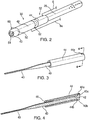
FIG. 2 is a perspective view of a plasma instrument of the system ofFIG. 1 ; -
FIG. 3 is a perspective view of an electrode assembly of the plasma instrument ofFIG. 2 ; -
FIG. 4 is a perspective, cross-sectional view of the electrode assembly ofFIG. 4 taken along a cross-sectional line 4-4; -
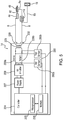
FIG. 5 is a schematic, block diagram of the plasma system ofFIG. 1 according to the present disclosure; and -
FIG. 6 is a flow chart of a method for generating plasma using the plasma system ofFIG. 1 . - Plasmas may be generated using electrical energy that is delivered as either direct current (DC) electricity or alternating current (AC) electricity at frequencies from about 0.1 hertz (Hz) to about 100 gigahertz (GHz), including radio frequency ("RF", from about 0.1 MHz to about 100 MHz) and microwave ("MW", from about 0.1 GHz to about 100 GHz) bands, using appropriate generators, electrodes, and antennas. Choice of excitation frequency, the workpiece, as well as the electrical circuits that are used to deliver electrical energy to the workpiece affect many properties of the plasma. The performance of the plasma chemical generation, the delivery system and the design of the electrical excitation circuitry are interrelated. Specifically, the choices of operating voltage, frequency, and current levels (as well as phase) affect the electron temperature and electron density. Further, choices of electrical excitation and plasma device hardware also determine how a given plasma system responds dynamically to the introduction of new ingredients to the host plasma gas or liquid media.
- Plasma effluent may be used to coagulate, cauterize, or otherwise treat tissue through direct application of high-energy plasma. In particular, kinetic energy transfer from the plasma to the tissue causes healing, and thus, provides for thermal coagulation of bleeding tissue. Plasma beam coagulation utilizes a handheld electrosurgical instrument having one or more electrodes that are energizable by an electrosurgical generator, which outputs a high-intensity electric field suitable for forming plasma using ionizable media (e.g., inert gas).
- Briefly, the present disclosure provides an electrosurgical system including a generator configured to generate energy that is transmitted to a plasma instrument, which is also coupled to a source of an ionizable medium. The excitation waveform generated by the generator ignites the ionizable medium flowing through the plasma device, thereby forming a plasma effluent. The electrosurgical system according to the present disclosure includes various sensors, such as an atmospheric sensor and a proximity sensor, which provide measurement signals used by the generator for igniting and maintaining the plasma effluent. In addition, the plasma instrument also includes a corona electrode that aides in ignition and formation of the plasma effluent.
- Referring initially to
FIG. 1 , aplasma system 10 is disclosed. Thesystem 10 includes aplasma instrument 12 that is coupled to agenerator 14, an ionizable media source 16 which may also include an optional precursor source (not shown).Generator 14 includes any suitable components for delivering power to theplasma instrument 12. More particularly, thegenerator 14 may be any radio frequency generator or other suitable power source capable of generating electrical power sufficient to ignite the ionizable media to generate plasma.Generator 14 may be an electrosurgical generator that is adapted to supply theinstrument 12 with electrical power at a frequency from about 100 kHz to about 4 MHz, in embodiments the frequency may range from about 200 kHz to about 3 MHz, and in further embodiments the frequency may range from about 300 kHz to about 1 MHz. - In embodiments, electrosurgical energy is supplied to the
instrument 12 by thegenerator 14 via aninstrument cable 4. Thecable 4 includes a supply lead 6 connecting theinstrument 12 to an active terminal 230 (FIG. 5 ) of thegenerator 14 and afirst return lead 8a connecting theinstrument 12 to a return terminal 232 (FIG. 5 ) of thegenerator 14. It is envisioned that theplasma instrument 12 may be utilized as an electrosurgical pencil for application of plasma to tissue. - The
system 10 also includes one or morereturn electrode pads 18 that, in use, are disposed on a patient to minimize the chances of tissue damage by maximizing the overall contact area with the patient. The energy is returned to thegenerator 14 through thereturn electrode pad 18 via asecond return lead 8b to the return terminal 232 (FIG. 5 ) of thegenerator 14. Return leads 8a and 8b are coupled to acommon return lead 8, which is in turn, connected to the return terminal 232 (FIG. 5 ). - The
plasma instrument 12 is shown as a catheter having ahandle 20 and a flexibleelongate body 22 having aproximal portion 24 coupled to thehandle 20 and adistal portion 26. Theelongate body 20 may be tubular and may be formed from any suitable flexible dielectric material, such as polyimide. Thehandle 20 also includes anarticulation mechanism 28 having awire 29, which extends the length of theelongate body 20. Thewire 29 may be wound or unwound by thearticulation mechanism 26 to articulate thedistal portion 26 of theelongate body 20. - With continued reference to
FIG. 1 , the ionizable media source 16 may be coupled to theplasma instrument 12 via tubing 15. The tubing 15 may be fed from multiple sources of ionizable media and/or precursor feedstocks, which may be combined into unified tubing to deliver a mixture of the ionizable media and the precursor feedstock to theinstrument 12 at a proximal end thereof. This allows for the plasma feedstocks, e.g., the precursor feedstock and the ionizable gas, to be delivered to theplasma instrument 12 simultaneously prior to ignition of the mixture therein. - The ionizable media source 16 may include various flow sensors and controllers (e.g., valves, mass flow controllers, etc.) to control the flow of ionizable media to the
instrument 12. During operation, the ionizable media and/or the precursor feedstock are provided to theplasma instrument 12 where the plasma feedstocks are ignited to form plasma effluent containing ions, radicals, and/or photons from the specific excited species and metastables that carry internal energy to drive desired chemical reactions in the workpiece or at the surface thereof. The feedstocks may be mixed upstream from the ignition point or midstream (e.g., at the ignition point) of the plasma effluent. - The ionizable media source 16 may include a storage tank, a pump, and/or flow meter (not explicitly shown). The ionizable media may be a liquid or a gas such as argon, helium, neon, krypton, xenon, radon, carbon dioxide, nitrogen, hydrogen, oxygen, etc. their mixtures, and the like. These and other gases may be initially in a liquid form that is gasified during application. The precursor feedstock may be either in solid, gaseous or liquid form and may be mixed with the ionizable media in any state, such as solid, liquid (e.g., particulates or droplets), gas, and combinations thereof.
- In another embodiment, the ionizable media and precursor feedstocks may be supplied at separate connections, such that the mixing of the feedstocks occurs within the
plasma instrument 12 upstream from the ignition point. In this manner, the plasma feedstocks are mixed proximally of the ignition point. - In a further embodiment, the plasma feedstocks may be mixed midstream, e.g., at the ignition point or downstream of the plasma effluent, directly into the plasma. It is also envisioned that the ionizable media may be supplied to the
instrument 12 proximally of the ignition point, while the precursor feedstocks are mixed therewith at the ignition point. In a further illustrative embodiment, the ionizable media may be ignited in an unmixed state and the precursors may be mixed directly into the ignited plasma. Prior to mixing, the plasma feedstocks may be ignited individually. The plasma feedstock may be supplied at a predetermined pressure to create a flow of the medium through theinstrument 12, which aids in the reaction of the plasma feedstocks and produces a plasma effluent. The plasma according to the present disclosure may be generated at or near atmospheric pressure under normal atmospheric conditions. - In one embodiment, the precursors may be any chemical species capable of forming reactive species such as ions, electrons, excited-state (e.g., metastable) species, molecular fragments (e.g., radicals), and the like, when ignited by electrical energy from the
generator 14 or when undergoing collisions with particles (electrons, photons, or other energy-bearing species of limited and selective chemical reactivity) formed from the ionizable media 16. More specifically, the precursors may include various reactive functional groups, such as acyl halide, alcohol, aldehyde, alkane, alkene, amide, amine, butyl, carboxlic, cyanate, isocyanate, ester, ether, ethyl, halide, haloalkane, hydroxyl, ketone, methyl, nitrate, nitro, nitrile, nitrite, nitroso, peroxide, hydroperoxide, oxygen, hydrogen, nitrogen, and combinations thereof. In embodiments, the precursor feedstocks may be water, halogenoalkanes, such as dichloromethane, tricholoromethane, carbon tetrachloride, difluoromethane, trifluoromethane, carbon tetrafluoride, and the like; peroxides, such as hydrogen peroxide, acetone peroxide, benzoyl peroxide, and the like; alcohols, such as methanol, ethanol, isopropanol, ethylene glycol, propylene glycol, alkalines such as NaOH, KOH, amines, alkyls, alkenes, and the like. Such precursor feedstocks may be applied in substantially pure, mixed, or soluble form. - With reference to
FIG. 2-4 , thedistal portion 26 of theelongate body 20 is coupled to aplasma applicator 30, which includes anactive electrode assembly 32. Theactive electrode assembly 32 includes an active electrode 40 (FIG. 3 ) having aproximal portion 42 and a distal portion 43 (FIG. 4 ). Theproximal portion 42 is enclosed in aconductive collar 44, which is coupled to the supply lead 6. The supply lead 6 is electrically coupled to an outer surface of theconductive collar 44 such that the supply lead 6 is disposed outside the gas flow within theelongate body 20. In embodiments, the supply lead 6 may be enclosed in an insulative sheath and be disposed within theelongate body 20. In further embodiments, the supply lead 6 may be disposed within the tubing of theelongate body 20, e.g., during the extrusion process. In yet another embodiment, the supply lead 6 may be coupled directly to theactive electrode 40. - The
conductive collar 44 has a substantially tubular shape defining a lumen 46 (FIG. 4 ) therethrough. Thedistal portion 26 of theelongate body 20 may be stretched over a distal portion of theconductive collar 44 to create a gas tight seal. Theconductive collar 44 may also include one ormore slots 44a and 44b configured to couple toextensions active electrode 40 to provide for an electrical and mechanical coupling therebetween. This connection also aligns theactive electrode 40 within theconductive collar 44. - The
active electrode 40 may have any suitable shape that does not obstruct thelumen 46, ensuring that ionizable medium may flow through thelumen 46. In embodiments, theactive electrode 40 may have a tapered configuration in which theproximal portion 42 is wider than thedistal portion 43 such that the change in width of theactive electrode 40 is gradual from theproximal portion 42 to thedistal portion 43. - The
distal portion 43 of theactive electrode 40 is enclosed in acorona electrode 48, which is coupled to thereturn lead 8a. Thereturn lead 8a may be coupled to the corona electrode 48 (FIG. 2 ) in any suitable manner as described above with respect to coupling the supply lead 6 to theconductive collar 44. Similarly to theconductive collar 44, thecorona electrode 48 may also have a substantially tubular shape defining a lumen (not shown) therethrough. Theplasma applicator 30 also includes anozzle 52 coupled to a distal end ofcorona electrode 48. Thenozzle 52 also defines alumen 54, in which thedistal portion 43 of theactive electrode 40 is disposed. - The
active electrode 40, theconductive collar 44, and thecorona electrode 48 may be formed from any suitable conductive material including metals, such as stainless steel, copper, aluminium, tungsten, and combinations and alloys thereof. Thenozzle 52 may be formed from any suitable dielectric material including thermoplastic materials if the temperature of the plasma is sufficiently low or any other suitable heat-resistant dielectric material, including ceramic materials. - In embodiments, the
plasma applicator 30 may also include a proximity sensor 60 (FIG. 2 ). Theproximity sensor 60 is used to measure the distance between the tissue and thenozzle 52. The measured distance is used by thegenerator 14 to control energy and thereby maintain the plasma. Theproximity sensor 60 may be an electromagnetic sensor configured to emit an electromagnetic field or a beam of electromagnetic radiation (e.g., visible light, infrared, etc.), and measure changes in the field or beam. In embodiments, theproximity sensor 60 may be a capacitive sensor configured to detect distance to tissue based on the dielectric properties thereof. - The
plasma applicator 30 may also include anatmospheric sensor 62, such as a humistor, configured to sense relative humidity in and around the surgical site. In embodiments, theatmospheric sensor 62 may be also include an oxygen sensor configured to measure concentration of oxygen in the surrounding atmosphere. -
FIG. 5 shows a schematic block diagram of thegenerator 14 configured to output electrosurgical energy. Thegenerator 14 includes acontroller 224, apower supply 227, and a radio-frequency (RF)amplifier 228. Thepower supply 227 may be a high voltage, DC power supply connected to an AC source (e.g., line voltage), provides high voltage, DC power to theRF amplifier 228, which then converts the high voltage, DC power into AC energy (e.g., electrosurgical or microwave) suitable to ignite the ionizable media, and delivers the energy to theactive terminal 230. The energy is returned thereto via thereturn terminal 232. The active and returnterminals RF amplifier 228 through anisolation transformer 229. TheRF amplifier 228 is configured to operate in a plurality of modes, during which thegenerator 14 outputs corresponding waveforms having specific duty cycles, peak voltages, crest factors, etc. It is envisioned that in other embodiments, thegenerator 14 may be based on other types of suitable power supply topologies. - The
controller 224 includes aprocessor 225 operably connected to amemory 226, which may include transitory type memory (e.g., RAM) and/or non-transitory type memory (e.g., flash media, disk media, etc.). Theprocessor 225 includes an output port that is operably connected to thepower supply 227 and/orRF amplifier 228 allowing theprocessor 225 to control the output of thegenerator 14 according to either open and/or closed control loop schemes. A closed loop control scheme is a feedback control loop, in which a plurality of sensors measure a variety of tissue and energy properties (e.g., tissue impedance, tissue temperature, output power, current, and/or voltage, etc.), and provide feedback to thecontroller 224. Thecontroller 224 then signals thepower supply 227 and/orRF amplifier 228, which adjusts the DC and/or power supply, respectively. Those skilled in the art will appreciate that theprocessor 225 may be substituted by using any logic processor (e.g., control circuit) adapted to perform the calculations and/or set of instructions described herein including, but not limited to, field programmable gate array, digital signal processor, and combinations thereof. - The
generator 14 according to the present disclosure includes a plurality ofsensors 280, e.g., an RFcurrent sensor 280a, and anRF voltage sensor 280b. Various components of thegenerator 14, namely, theRF amplifier 228, and the RF current andvoltage sensors current sensor 280a is coupled to theactive terminal 230 and provides measurements of the RF current supplied by theRF amplifier 228. In embodiments the RFcurrent sensor 280a may be coupled to thereturn terminal 232. TheRF voltage sensor 280b is coupled to the active and returnterminals RF amplifier 228. In embodiments, the RF current andvoltage sensors terminals RF amplifier 228, respectively. - The RF current and
voltage sensors controller 224, which then may adjust output of thepower supply 227 and/or theRF amplifier 228 in response to the sensed RF voltage and current signals. Thecontroller 224 also receives input signals from the input controls of thegenerator 14 and/or theplasma instrument 12. Thecontroller 224 utilizes the input signals to adjust the power output of thegenerator 14 and/or performs other control functions thereon. - The
controller 224 is also coupled to theproximity sensor 60 and the atmospheric sensor 62 (FIG. 2 ). Thecontroller 224 operates thegenerator 14 based on the sensor signals from theproximity sensor 60 and theatmospheric sensor 62. In embodiments, thecontroller 224 may also be configured to control the ionizable media source 16 (FIG. 1 ), such as the flow rate of the ionizable media, based on the sensor readings. - With continued reference to
FIG. 5 , thecontroller 224 is also configured to control the output of thegenerator 14 to ensure proper ignition of the plasma effluent. In that respect, thegenerator 14 includes aswitching element 9 coupled to thefirst return lead 8a. The switchingelement 9 controls the degree of coupling of thecorona electrode 48 to thegenerator 14. - The switching
element 9 may be a resistor, a variable resistor, a switch or combinations of these components. In embodiments, the switchingelement 9 may be coupled to thereturn lead 8 in parallel such that the switchingelement 9 may be switched in and out of the combined circuit. The switch state and/or the resistance of theswitching element 9 may be controlled by thecontroller 224. The resistance provided by the switchingelement 9 is used to control the amount of power delivered to thecorona electrode 48. In particular, where the switchingelement 9 is a variable resistor the resistance may be lowered to ensure that most of the power is delivered to the surgical site through theactive electrode 40 and thecorona electrode 48 to commence plasma generation. After the plasma has been ignited, thecontroller 224 may then increase resistance of theswitching element 9 to a level higher than the starting level to maintain plasma. - In embodiments where the switching
element 9 is a switchable resistor, to commence plasma generation the switchingelement 9 may be initially disconnected from the combinedreturn lead 8 by thecontroller 224. Once the plasma has commenced, the switchingelement 9 may then be switched on to maintain plasma generation. - In another embodiment, the switching
element 9 may be a switch, such that after the plasma is started, thecontroller 224 disconnects thecorona electrode 48 by deactivating the switch. In further embodiments, theplasma applicator 30 may include a plurality ofcorona assemblies 48 each of which is coupled to thegenerator 14 by thereturn lead 8a having the switchingelement 9. In this configuration, thecontroller 224 controls each of thecorona assemblies 48 in the manner described above. - In other words, when the
corona electrode 48 is coupled to thecommon return lead 8 due to theswitching element 9 being activated or the resistance of theswitching element 9 being lowered, the power is split between thecorona electrode 48 and thereturn electrode pad 18. When thecorona electrode 48 is disconnected from thecommon return lead 8 due to theswitching element 9 being deactivated or the resistance of theswitching element 9 being increased, the power is returned mostly through thereturn electrode pad 18. With respect to theswitching element 9 being a variable resistor, the effect of thecorona electrode 48 on plasma generation may be varied based on a desired effect. - As noted above, the
controller 224 is also coupled to theproximity sensor 60 and theatmospheric sensor 62. The sensor data from theproximity sensor 60 and theatmospheric sensor 62 is used by thecontroller 224 to control the plasma ignition process, and in particular, the coupling of thecorona electrode 48 to thegenerator 14. Theproximity sensor 60 provides information regarding the distance separating theplasma applicator 30 from tissue. Thecontroller 224 utilizes the distance information from theproximity sensor 60 in determining whether energy from thegenerator 14 may be supplied to theplasma applicator 30 to commence treatment. If theproximity sensor 60 detects that theapplicator 30 is contacting tissue, then thecontroller 224 prevents application of energy. In embodiments, thecontroller 224 is also configured to control energy output based on the measured distance, such as increasing energy as the distance between theapplicator 30 and the tissue increases and decreasing energy as the distance decreases. - The
atmospheric sensor 62 provides data to thecontroller 224 regarding the atmosphere surrounding theplasma applicator 30, the data including oxygen saturation, pressure, relative humidity, and the like. Thecontroller 224 utilizes this data in controlling energy delivered to theplasma applicator 30. Humidity and density of the atmosphere, e.g., oxygen saturation, play an important role in the effectiveness of the plasma. Decreased oxygen saturation and increased humidity adversely affect plasma performance, and therefore, thecontroller 224 adjusts the output of thegenerator 14 such that the energy supplied by thegenerator 14 compensates for any adverse atmospheric effects as measured by theatmospheric sensor 62. - With reference to
FIG. 6 , a method for operating thesystem 10 according to the present disclosure, initially includes measuring the distance and atmospheric conditions of theplasma applicator 30. The measurements are transmitted to thecontroller 224, which determines operating parameters of thegenerator 14 based on the measurements. If theplasma applicator 30 is detected to be contacting tissue, thecontroller 224 may output an error signal, indicating that theplasma applicator 30 may need to be repositioned to avoid contact. Once thecontroller 224 determines that theplasma applicator 30 is separated by a sufficient distance, thecontroller 224 adjusts resistivity of theswitching element 9 and/or activates the switchingelement 9 depending on the configuration of theswitching element 9 and the combinedreturn lead 8. In embodiments where thecorona electrode 48 is connected via a switch (not shown) instead of theswitching element 9, then the switch is actuated by thecontroller 224. - After the distance and resistance are set and/or determined by the
controller 224 to be within prescribed operating parameters, thecontroller 224 signals thegenerator 14 to output energy to ignite plasma. Thecontroller 224 calculates the initial energy output in view of the atmospheric conditions, distance, and resistance. In embodiments where resistivity is adjustable, resistivity of theswitching element 9 may also be calculated by thecontroller 224. Thereafter, thegenerator 14 outputs energy based on these calculations. - After plasma has been ignited at the
plasma applicator 30, thecontroller 224 deactivates the switchingelement 9 and/or adjusts the resistivity thereof to a desired level to maintain the plasma. Additionally, thecontroller 224 may also utilize the measurements from theproximity sensor 60 and theatmospheric sensor 62 after the plasma has been ignited to make adjustments to the output of thegenerator 14. - Although the illustrative embodiments of the present disclosure have been described herein with reference to the accompanying drawings, it is to be understood that the disclosure is not limited to those precise embodiments, and that various other changes and modifications may be effected therein by one skilled in the art without departing from the scope or spirit of the disclosure. In particular, as discussed above this allows the tailoring of the relative populations of plasma species to meet needs for the specific process desired on the workpiece surface or in the volume of the reactive plasma.
- The invention may be described by reference to the following numbered paragraphs:-
- 1. A plasma instrument comprising:
- an elongated body defining a lumen therethrough, the lumen being in fluid communication with an ionizable media source;
- a plasma applicator coupled to a distal portion of the elongated body, the plasma applicator including:
- an active electrode configured to couple to an active terminal of a generator; and
- a corona electrode configured to couple to a return terminal of a generator; and
- a switching element coupled to the corona electrode, the switching element configured to control at least one of resistivity or connectivity of the corona electrode to a generator.
- 2. The plasma instrument according to paragraph 1, further comprising a proximity sensor configured to measure a distance between the plasma applicator and tissue.
- 3. The plasma instrument according to paragraph 1, further comprising an atmospheric sensor configured to measure a property of air surrounding the plasma applicator.
- 4. The plasma instrument according to paragraph 1, wherein the plasma applicator further includes a nozzle coupled to a distal portion of the corona electrode.
- 5. The plasma instrument according to
paragraph 4, wherein the active electrode extends through the corona electrode and at least partially through the nozzle. - 6. The plasma instrument according to paragraph 1, wherein the elongated body is flexible.
- 7. A plasma system comprising:
- a generator having an active terminal and a return terminal;
- an ionizable media source;
- a plasma instrument including:
- an elongated body defining a lumen therethrough, the lumen being in fluid communication with the ionizable media source;
- a plasma applicator coupled to a distal portion of the elongated body, the plasma applicator including:
- an active electrode coupled to the active terminal of the generator; and
- a corona electrode coupled to the return terminal of the generator; and
- a switching element coupled to the corona electrode, the switching element configured to control at least one of resistivity or connectivity of the corona electrode to the generator.
- 8. The plasma system according to paragraph 7, further comprising a return electrode pad coupled to the return terminal.
- 9. The plasma system according to
paragraph 8, further comprising:- a first return lead coupled to the corona electrode;
- a second return lead coupled to the return electrode pad; and
- a common return lead coupled to the first and second return leads, the common return lead being coupled to the return terminal.
- 10. The plasma system according to paragraph 7, wherein the plasma instrument further includes a proximity sensor configured to measure a distance between the plasma applicator and tissue.
- 11. The plasma system according to
paragraph 10, wherein the generator includes a controller coupled to the proximity sensor, the controller configured to control at least one of energy output of the generator or a state of the switching element based on the distance. - 12. The plasma system according to paragraph 7, wherein the plasma instrument further includes an atmospheric sensor configured to measure an air property surrounding the plasma applicator.
- 13. The plasma system according to
paragraph 12, wherein the generator includes a controller coupled to the atmospheric sensor, the controller configured to control at least one of energy output of the generator or a state of the switching element based on the air property. - 14. The plasma system according to
paragraph 12, wherein the air property is selected from the group consisting of humidity and oxygen saturation. - 15. The plasma system according to paragraph 7, wherein the plasma applicator further includes a nozzle coupled to a distal portion of the corona electrode.
- 16. The plasma system according to paragraph 15, wherein the active electrode extends through the corona electrode and at least partially through the nozzle.
- 17. The plasma system according to paragraph 7, wherein the elongated body is flexible.
Claims (15)
- A plasma instrument comprising:an elongated body defining a lumen therethrough, the lumen being in fluid communication with an ionizable media source;a plasma applicator coupled to a distal portion of the elongated body, the plasma applicator including:an active electrode configured to couple to an active terminal of a generator; anda corona electrode configured to couple to a return terminal of a generator; anda switching element coupled to the corona electrode, the switching element configured to control at least one of resistivity or connectivity of the corona electrode to a generator.
- The plasma instrument according to claim 1, further comprising a proximity sensor configured to measure a distance between the plasma applicator and tissue.
- The plasma instrument according to claim 1 or 2, further comprising an atmospheric sensor configured to measure a property of air surrounding the plasma applicator.
- The plasma instrument according to claim 1, 2 or 3, wherein the plasma applicator further includes a nozzle coupled to a distal portion of the corona electrode.
- The plasma instrument according to claim 4, wherein the active electrode extends through the corona electrode and at least partially through the nozzle.
- The plasma instrument according to claim 1, wherein the elongated body is flexible.
- A plasma system comprising:a generator having an active terminal and a return terminal;an ionizable media source;a plasma instrument including:an elongated body defining a lumen therethrough, the lumen being in fluid communication with the ionizable media source;a plasma applicator coupled to a distal portion of the elongated body, the plasma applicator including:an active electrode coupled to the active terminal of the generator; anda corona electrode coupled to the return terminal of the generator; anda switching element coupled to the corona electrode, the switching element configured to control at least one of resistivity or connectivity of the corona electrode to the generator.
- The plasma system according to claim 7, further comprising a return electrode pad coupled to the return terminal.
- The plasma system according to claim 8, further comprising:a first return lead coupled to the corona electrode;a second return lead coupled to the return electrode pad; anda common return lead coupled to the first and second return leads, the common return lead being coupled to the return terminal.
- The plasma system according to claim 7, 8 or 9, wherein the plasma instrument further includes a proximity sensor configured to measure a distance between the plasma applicator and tissue.
- The plasma system according to claim 10, wherein the generator includes a controller coupled to the proximity sensor, the controller configured to control at least one of energy output of the generator or a state of the switching element based on the distance.
- The plasma system according to any one of claims 7 to 11, wherein the plasma instrument further includes an atmospheric sensor configured to measure an air property surrounding the plasma applicator.
- The plasma system according to claim 12, wherein the generator includes a controller coupled to the atmospheric sensor, the controller configured to control at least one of energy output of the generator or a state of the switching element based on the air property.
- The plasma system according to claim 12 or 13, wherein the air property is selected from the group consisting of humidity and oxygen saturation.
- The plasma system according to anyone of claims 7 to 14, wherein the plasma applicator further includes a nozzle coupled to a distal portion of the corona electrode, prefereably wherein the active electrode extends through the corona electrode and at least partially through the nozzle, and further preferably wherein the elongated body is flexible.
Applications Claiming Priority (2)
| Application Number | Priority Date | Filing Date | Title |
|---|---|---|---|
| US201662370035P | 2016-08-02 | 2016-08-02 | |
| US15/645,522 US10524849B2 (en) | 2016-08-02 | 2017-07-10 | System and method for catheter-based plasma coagulation |
Publications (2)
| Publication Number | Publication Date |
|---|---|
| EP3292830A1 true EP3292830A1 (en) | 2018-03-14 |
| EP3292830B1 EP3292830B1 (en) | 2022-02-23 |
Family
ID=61071894
Family Applications (1)
| Application Number | Title | Priority Date | Filing Date |
|---|---|---|---|
| EP17184185.1A Not-in-force EP3292830B1 (en) | 2016-08-02 | 2017-08-01 | System for catheter-based plasma coagulation |
Country Status (2)
| Country | Link |
|---|---|
| US (2) | US10524849B2 (en) |
| EP (1) | EP3292830B1 (en) |
Families Citing this family (5)
| Publication number | Priority date | Publication date | Assignee | Title |
|---|---|---|---|---|
| CA2884145C (en) * | 2012-09-11 | 2017-03-14 | American Eagle Instruments, Inc. | Electrical discharge irrigator apparatus and method |
| US10898705B2 (en) | 2012-09-11 | 2021-01-26 | G&H Technologies, Llc | Electrical discharge irrigator apparatus and method |
| US11304750B2 (en) * | 2017-08-09 | 2022-04-19 | The Penn State Research Foundation | Low-temperature plasma catheter for less-invasive, localized treatment of endocarditis and atherosclerosis |
| CN116725650A (en) * | 2023-05-26 | 2023-09-12 | 运医之星(上海)科技有限公司 | A low-temperature plasma surgery system and plasma electrode |
| US12486752B1 (en) | 2024-05-31 | 2025-12-02 | Halliburton Energy Services, Inc. | Monitoring hydraulic fracturing of a well using pressure waves |
Citations (6)
| Publication number | Priority date | Publication date | Assignee | Title |
|---|---|---|---|---|
| US4781175A (en) * | 1986-04-08 | 1988-11-01 | C. R. Bard, Inc. | Electrosurgical conductive gas stream technique of achieving improved eschar for coagulation |
| JPH11290335A (en) * | 1998-04-06 | 1999-10-26 | Mecs Corp | Electric surgical apparatus |
| EP1595507A2 (en) * | 1999-10-05 | 2005-11-16 | Sherwood Services AG | Articulating ionizable gas coagulator |
| US20120289954A1 (en) * | 2009-11-09 | 2012-11-15 | Amnon Lam | Micro plasma head for medical applications |
| EP2777580A2 (en) * | 2013-03-15 | 2014-09-17 | Covidien LP | Bipolar gas plasma coagulation nozzle |
| JP2016500318A (en) * | 2012-12-21 | 2016-01-12 | ノースシーオー ヴェンチャーズ ゲーエムベーハー アンド ツェーオー.カーゲーNorthco Ventures Gmbh & Co.Kg | Apparatus and method for treating biological tissue using low pressure plasma |
Family Cites Families (84)
| Publication number | Priority date | Publication date | Assignee | Title |
|---|---|---|---|---|
| FR1340509A (en) | 1962-11-27 | 1963-10-18 | Siemens Reiniger Werke Ag | Safety device for high frequency surgical devices |
| US3434476A (en) | 1966-04-07 | 1969-03-25 | Robert F Shaw | Plasma arc scalpel |
| US3492074A (en) | 1967-11-24 | 1970-01-27 | Hewlett Packard Co | Atomic absorption spectroscopy system having sample dissociation energy control |
| US3687832A (en) | 1970-11-23 | 1972-08-29 | Surface Activation Corp | Production of improved polymeric materials using electrical gas discharges |
| US3838242A (en) * | 1972-05-25 | 1974-09-24 | Hogle Kearns Int | Surgical instrument employing electrically neutral, d.c. induced cold plasma |
| US4188426A (en) | 1977-12-12 | 1980-02-12 | Lord Corporation | Cold plasma modification of organic and inorganic surfaces |
| US4517495A (en) | 1982-09-21 | 1985-05-14 | Piepmeier Edward H | Multi-electrode plasma source |
| US4699082A (en) | 1983-02-25 | 1987-10-13 | Liburdi Engineering Limited | Apparatus for chemical vapor deposition |
| JPS61159953A (en) | 1985-01-08 | 1986-07-19 | オリンパス光学工業株式会社 | Prostate cutting apparatus |
| CH670171A5 (en) | 1986-07-22 | 1989-05-12 | Bbc Brown Boveri & Cie | |
| DE3670022D1 (en) | 1986-08-11 | 1990-05-10 | Mo Med Inst Pirogova | DEVICE FOR CUTTING BIOLOGICAL TISSUES WITH PLASMA BOWS. |
| SU1438745A1 (en) | 1986-12-24 | 1988-11-23 | Всесоюзный научно-исследовательский и испытательный институт медицинской техники | Ultrasonic surgical instrument |
| CH677292A5 (en) | 1989-02-27 | 1991-04-30 | Asea Brown Boveri | |
| US5024617A (en) | 1989-03-03 | 1991-06-18 | Wilson-Cook Medical, Inc. | Sphincterotomy method and device having controlled bending and orientation |
| US5041110A (en) | 1989-07-10 | 1991-08-20 | Beacon Laboratories, Inc. | Cart for mobilizing and interfacing use of an electrosurgical generator and inert gas supply |
| DE59105798D1 (en) | 1991-04-15 | 1995-07-27 | Heraeus Noblelight Gmbh | Irradiation facility. |
| DE4139029C2 (en) | 1991-11-27 | 1996-05-23 | Erbe Elektromedizin | Device for the coagulation of biological tissues |
| DE9117299U1 (en) | 1991-11-27 | 2000-03-23 | Erbe Elektromedizin GmbH, 72072 Tübingen | Device for the coagulation of biological tissue |
| DE9117019U1 (en) | 1991-11-27 | 1995-03-09 | Erbe Elektromedizin GmbH, 72072 Tübingen | Device for the coagulation of biological tissues |
| JPH06196419A (en) | 1992-12-24 | 1994-07-15 | Canon Inc | Chemical vapor deposition apparatus and semiconductor device manufacturing method using the same |
| US5466424A (en) | 1992-12-28 | 1995-11-14 | Bridgestone Corporation | Corona discharge surface treating method |
| DE4326037C2 (en) | 1993-08-03 | 1997-01-16 | Dieter C Dr Med Goebel | Laser device |
| US5780862A (en) | 1994-01-11 | 1998-07-14 | Siess; Harold E. | Method and apparatus for generating ions |
| US6602248B1 (en) | 1995-06-07 | 2003-08-05 | Arthro Care Corp. | Methods for repairing damaged intervertebral discs |
| US6264650B1 (en) | 1995-06-07 | 2001-07-24 | Arthrocare Corporation | Methods for electrosurgical treatment of intervertebral discs |
| US6203542B1 (en) | 1995-06-07 | 2001-03-20 | Arthrocare Corporation | Method for electrosurgical treatment of submucosal tissue |
| US6159208A (en) | 1995-06-07 | 2000-12-12 | Arthocare Corporation | System and methods for electrosurgical treatment of obstructive sleep disorders |
| US20050004634A1 (en) | 1995-06-07 | 2005-01-06 | Arthrocare Corporation | Methods for electrosurgical treatment of spinal tissue |
| US6772012B2 (en) | 1995-06-07 | 2004-08-03 | Arthrocare Corporation | Methods for electrosurgical treatment of spinal tissue |
| US7179255B2 (en) | 1995-06-07 | 2007-02-20 | Arthrocare Corporation | Methods for targeted electrosurgery on contained herniated discs |
| US7090672B2 (en) | 1995-06-07 | 2006-08-15 | Arthrocare Corporation | Method for treating obstructive sleep disorder includes removing tissue from the base of tongue |
| US7393351B2 (en) | 1995-06-07 | 2008-07-01 | Arthrocare Corporation | Apparatus and methods for treating cervical inter-vertebral discs |
| DE19524645C2 (en) | 1995-07-06 | 2002-11-28 | Soering Gmbh | Safety gas system for HF surgery |
| DE19537897A1 (en) | 1995-09-19 | 1997-03-20 | Erbe Elektromedizin | Multi=functional surgical instrument suitable for variable surgical methods |
| DE29724247U1 (en) | 1997-03-20 | 2000-08-03 | Erbe Elektromedizin GmbH, 72072 Tübingen | Device for the coagulation of biological tissue |
| US5866871A (en) | 1997-04-28 | 1999-02-02 | Birx; Daniel | Plasma gun and methods for the use thereof |
| US6172324B1 (en) | 1997-04-28 | 2001-01-09 | Science Research Laboratory, Inc. | Plasma focus radiation source |
| US7094215B2 (en) | 1997-10-02 | 2006-08-22 | Arthrocare Corporation | Systems and methods for electrosurgical tissue contraction |
| US5869832A (en) | 1997-10-14 | 1999-02-09 | University Of Washington | Device and method for forming ions |
| US5945790A (en) | 1997-11-17 | 1999-08-31 | Schaefer; Raymond B. | Surface discharge lamp |
| DE19820240C2 (en) | 1998-05-06 | 2002-07-11 | Erbe Elektromedizin | Electrosurgical instrument |
| US6265033B1 (en) | 1998-09-11 | 2001-07-24 | Donald Bennett Hilliard | Method for optically coupled vapor deposition |
| DE19844725A1 (en) | 1998-09-29 | 2000-03-30 | Patent Treuhand Ges Fuer Elektrische Gluehlampen Mbh | Gas discharge lamp with controllable light length |
| DE19848784C2 (en) | 1998-10-22 | 2003-05-08 | Erbe Elektromedizin | probe |
| US6376972B1 (en) | 1998-11-19 | 2002-04-23 | The United States Of America As Represented By The United States Department Of Energy | Powerful glow discharge excilamp |
| US6153852A (en) | 1999-02-12 | 2000-11-28 | Thermal Conversion Corp | Use of a chemically reactive plasma for thermal-chemical processes |
| JP3264898B2 (en) | 1999-02-25 | 2002-03-11 | 大村 智 | Ultraviolet irradiation equipment for sterilization of liquid and muddy substances |
| US6475217B1 (en) | 1999-10-05 | 2002-11-05 | Sherwood Services Ag | Articulating ionizable gas coagulator |
| CN2391565Y (en) | 1999-10-20 | 2000-08-16 | 赵学良 | Automatic smoke removing type ionizing surgical instrument |
| US7300436B2 (en) | 2000-02-22 | 2007-11-27 | Rhytec Limited | Tissue resurfacing |
| EP1288174A4 (en) | 2000-04-28 | 2005-06-08 | Asahi Glass Co Ltd | COATED GLASS OF THERMO-REFLECTOR COLORED FILM AND METHOD OF MANUFACTURING THE SAME |
| US7070596B1 (en) | 2000-08-09 | 2006-07-04 | Arthrocare Corporation | Electrosurgical apparatus having a curved distal section |
| US20030158545A1 (en) | 2000-09-28 | 2003-08-21 | Arthrocare Corporation | Methods and apparatus for treating back pain |
| US6475215B1 (en) | 2000-10-12 | 2002-11-05 | Naim Erturk Tanrisever | Quantum energy surgical device and method |
| CN1273856C (en) | 2000-12-14 | 2006-09-06 | 皇家菲利浦电子有限公司 | Liquid crystal display laminate and method of manufacturing such |
| CN1872363A (en) | 2001-03-02 | 2006-12-06 | 帕洛玛医疗技术公司 | Apparatus and method for photocosmetic and photodermatological treatment |
| US6837884B2 (en) | 2001-06-18 | 2005-01-04 | Arthrocare Corporation | Electrosurgical apparatus having compound return electrode |
| AU2002362310A1 (en) | 2001-09-14 | 2003-04-01 | Arthrocare Corporation | Methods and apparatus for treating intervertebral discs |
| US20030088245A1 (en) | 2001-11-02 | 2003-05-08 | Arthrocare Corporation | Methods and apparatus for electrosurgical ventriculostomy |
| US7004941B2 (en) | 2001-11-08 | 2006-02-28 | Arthrocare Corporation | Systems and methods for electrosurigical treatment of obstructive sleep disorders |
| US20050261754A1 (en) | 2003-02-26 | 2005-11-24 | Arthrocare Corporation | Methods and apparatus for treating back pain |
| WO2005039390A2 (en) | 2003-10-20 | 2005-05-06 | Arthrocare Corporation | Electrosurgical method and apparatus for removing tissue within a bone body |
| US8157795B2 (en) | 2004-02-03 | 2012-04-17 | Covidien Ag | Portable argon system |
| US7628787B2 (en) * | 2004-02-03 | 2009-12-08 | Covidien Ag | Self contained, gas-enhanced surgical instrument |
| US8048101B2 (en) | 2004-02-25 | 2011-11-01 | Femasys Inc. | Methods and devices for conduit occlusion |
| US8075732B2 (en) | 2004-11-01 | 2011-12-13 | Cymer, Inc. | EUV collector debris management |
| US7491200B2 (en) | 2004-03-26 | 2009-02-17 | Arthrocare Corporation | Method for treating obstructive sleep disorder includes removing tissue from base of tongue |
| US7608839B2 (en) | 2005-08-05 | 2009-10-27 | Mcgill University | Plasma source and applications thereof |
| US7511281B2 (en) | 2005-08-31 | 2009-03-31 | Ultraviolet Sciences, Inc. | Ultraviolet light treatment chamber |
| US20070106288A1 (en) | 2005-11-09 | 2007-05-10 | Arthrocare Corporation | Electrosurgical apparatus with fluid flow regulator |
| US7914692B2 (en) | 2006-08-29 | 2011-03-29 | Ngk Insulators, Ltd. | Methods of generating plasma, of etching an organic material film, of generating minus ions, of oxidation and nitriding |
| ES2565245T3 (en) | 2007-12-20 | 2016-04-01 | Günter Farin | Plasma applicators for plasma surgical procedures |
| WO2009146432A1 (en) | 2008-05-30 | 2009-12-03 | Colorado State University Research Foundation | Plasma-based chemical source device and method of use thereof |
| US20100204690A1 (en) | 2008-08-13 | 2010-08-12 | Arthrocare Corporation | Single aperture electrode assembly |
| KR101158800B1 (en) | 2008-11-14 | 2012-06-26 | 주식회사 피에스엠 | Plasma gun for medical treatment |
| KR101044314B1 (en) | 2008-11-25 | 2011-06-29 | 포항공과대학교 산학협력단 | Hemostatic device using low temperature plasma |
| JP2010242857A (en) | 2009-04-06 | 2010-10-28 | Toyota Motor Corp | Gear transmission that displaces meshing position to reduce friction loss |
| US20110301414A1 (en) * | 2010-06-04 | 2011-12-08 | Robert Hotto | Intelligent endoscopy systems and methods |
| US20140200506A1 (en) * | 2011-09-17 | 2014-07-17 | M.O.E. Medical Devices Llc | Systems, methods and machine readable programs for electric field and/or plasma-assisted onychomycosis treatment |
| US20130261536A1 (en) | 2012-03-27 | 2013-10-03 | Tyco Healthcare Group Lp | System and Method for Cholecystectomy |
| US9269544B2 (en) | 2013-02-11 | 2016-02-23 | Colorado State University Research Foundation | System and method for treatment of biofilms |
| US9117636B2 (en) | 2013-02-11 | 2015-08-25 | Colorado State University Research Foundation | Plasma catalyst chemical reaction apparatus |
| US20140228833A1 (en) | 2013-02-12 | 2014-08-14 | Covidien Lp | System and method for hybrid polarized/non-polarized plasma beam coagulation for variable tissue effects |
| US9532826B2 (en) | 2013-03-06 | 2017-01-03 | Covidien Lp | System and method for sinus surgery |
-
2017
- 2017-07-10 US US15/645,522 patent/US10524849B2/en active Active
- 2017-08-01 EP EP17184185.1A patent/EP3292830B1/en not_active Not-in-force
-
2020
- 2020-01-06 US US16/735,382 patent/US11376058B2/en active Active
Patent Citations (6)
| Publication number | Priority date | Publication date | Assignee | Title |
|---|---|---|---|---|
| US4781175A (en) * | 1986-04-08 | 1988-11-01 | C. R. Bard, Inc. | Electrosurgical conductive gas stream technique of achieving improved eschar for coagulation |
| JPH11290335A (en) * | 1998-04-06 | 1999-10-26 | Mecs Corp | Electric surgical apparatus |
| EP1595507A2 (en) * | 1999-10-05 | 2005-11-16 | Sherwood Services AG | Articulating ionizable gas coagulator |
| US20120289954A1 (en) * | 2009-11-09 | 2012-11-15 | Amnon Lam | Micro plasma head for medical applications |
| JP2016500318A (en) * | 2012-12-21 | 2016-01-12 | ノースシーオー ヴェンチャーズ ゲーエムベーハー アンド ツェーオー.カーゲーNorthco Ventures Gmbh & Co.Kg | Apparatus and method for treating biological tissue using low pressure plasma |
| EP2777580A2 (en) * | 2013-03-15 | 2014-09-17 | Covidien LP | Bipolar gas plasma coagulation nozzle |
Also Published As
| Publication number | Publication date |
|---|---|
| US10524849B2 (en) | 2020-01-07 |
| EP3292830B1 (en) | 2022-02-23 |
| US11376058B2 (en) | 2022-07-05 |
| US20180036059A1 (en) | 2018-02-08 |
| US20200138503A1 (en) | 2020-05-07 |
Similar Documents
| Publication | Publication Date | Title |
|---|---|---|
| US11376058B2 (en) | System and method for catheter-based plasma coagulation | |
| US10750605B2 (en) | Variable frequency excitation plasma device for thermal and non-thermal tissue effects | |
| US10898255B2 (en) | Bipolar plasma catheter | |
| US20140276717A1 (en) | Bipolar gas plasma coagulation nozzle | |
| CN105592886B (en) | Difunctional plasma and unionized microwave condenses electrosurgical unit and integrates the electrosurgery unit that the difunctional plasma and unionized microwave condense electrosurgical unit | |
| EP2789305B1 (en) | Multi-mode electrosurgical apparatus | |
| JP5579726B2 (en) | Tissue ablation system | |
| KR102323636B1 (en) | Surgical snare with ability to deliver electromagnetic energy and/or thermal plasma into biological tissue | |
| US9713242B2 (en) | Plasma treatment equipment | |
| KR20180123005A (en) | An electrosurgical instrument with multiple processing modes | |
| EP0998248A1 (en) | Electrosurgical systems and methods for recanalization of occluded body lumens | |
| CN102006831A (en) | Plasma applicators for plasma surgical procedures | |
| US20130261536A1 (en) | System and Method for Cholecystectomy | |
| EP2765838B1 (en) | System and method for controlling a hybrid polarized/non-polarized plasma beam | |
| WO2023150312A1 (en) | Electrosurgical system with adaptive non-thermal plasma control | |
| HK1222310B (en) | Surgical snare with ability to deliver electromagnetic energy and/or thermal plasma into biological tissue | |
| HK1219246B (en) | Dual-function plasma and non-ionising microwave coagulating electrosurgical instrument and electrosurgical apparatus incorporating the same |
Legal Events
| Date | Code | Title | Description |
|---|---|---|---|
| PUAI | Public reference made under article 153(3) epc to a published international application that has entered the european phase |
Free format text: ORIGINAL CODE: 0009012 |
|
| STAA | Information on the status of an ep patent application or granted ep patent |
Free format text: STATUS: REQUEST FOR EXAMINATION WAS MADE |
|
| 17P | Request for examination filed |
Effective date: 20170801 |
|
| AK | Designated contracting states |
Kind code of ref document: A1 Designated state(s): AL AT BE BG CH CY CZ DE DK EE ES FI FR GB GR HR HU IE IS IT LI LT LU LV MC MK MT NL NO PL PT RO RS SE SI SK SM TR |
|
| AX | Request for extension of the european patent |
Extension state: BA ME |
|
| RBV | Designated contracting states (corrected) |
Designated state(s): AL AT BE BG CH CY CZ DE DK EE ES FI FR GB GR HR HU IE IS IT LI LT LU LV MC MK MT NL NO PL PT RO RS SE SI SK SM TR |
|
| RIC1 | Information provided on ipc code assigned before grant |
Ipc: A61B 90/00 20160101ALN20210712BHEP Ipc: A61B 18/00 20060101ALN20210712BHEP Ipc: A61B 18/04 20060101AFI20210712BHEP |
|
| GRAP | Despatch of communication of intention to grant a patent |
Free format text: ORIGINAL CODE: EPIDOSNIGR1 |
|
| STAA | Information on the status of an ep patent application or granted ep patent |
Free format text: STATUS: GRANT OF PATENT IS INTENDED |
|
| RIC1 | Information provided on ipc code assigned before grant |
Ipc: A61B 90/00 20160101ALN20210825BHEP Ipc: A61B 18/00 20060101ALN20210825BHEP Ipc: A61B 18/04 20060101AFI20210825BHEP |
|
| INTG | Intention to grant announced |
Effective date: 20210910 |
|
| GRAS | Grant fee paid |
Free format text: ORIGINAL CODE: EPIDOSNIGR3 |
|
| GRAA | (expected) grant |
Free format text: ORIGINAL CODE: 0009210 |
|
| STAA | Information on the status of an ep patent application or granted ep patent |
Free format text: STATUS: THE PATENT HAS BEEN GRANTED |
|
| AK | Designated contracting states |
Kind code of ref document: B1 Designated state(s): AL AT BE BG CH CY CZ DE DK EE ES FI FR GB GR HR HU IE IS IT LI LT LU LV MC MK MT NL NO PL PT RO RS SE SI SK SM TR |
|
| REG | Reference to a national code |
Ref country code: GB Ref legal event code: FG4D |
|
| REG | Reference to a national code |
Ref country code: CH Ref legal event code: EP |
|
| REG | Reference to a national code |
Ref country code: DE Ref legal event code: R096 Ref document number: 602017053628 Country of ref document: DE |
|
| REG | Reference to a national code |
Ref country code: AT Ref legal event code: REF Ref document number: 1469851 Country of ref document: AT Kind code of ref document: T Effective date: 20220315 |
|
| REG | Reference to a national code |
Ref country code: IE Ref legal event code: FG4D |
|
| REG | Reference to a national code |
Ref country code: LT Ref legal event code: MG9D |
|
| REG | Reference to a national code |
Ref country code: NL Ref legal event code: MP Effective date: 20220223 |
|
| REG | Reference to a national code |
Ref country code: AT Ref legal event code: MK05 Ref document number: 1469851 Country of ref document: AT Kind code of ref document: T Effective date: 20220223 |
|
| PG25 | Lapsed in a contracting state [announced via postgrant information from national office to epo] |
Ref country code: SE Free format text: LAPSE BECAUSE OF FAILURE TO SUBMIT A TRANSLATION OF THE DESCRIPTION OR TO PAY THE FEE WITHIN THE PRESCRIBED TIME-LIMIT Effective date: 20220223 Ref country code: RS Free format text: LAPSE BECAUSE OF FAILURE TO SUBMIT A TRANSLATION OF THE DESCRIPTION OR TO PAY THE FEE WITHIN THE PRESCRIBED TIME-LIMIT Effective date: 20220223 Ref country code: PT Free format text: LAPSE BECAUSE OF FAILURE TO SUBMIT A TRANSLATION OF THE DESCRIPTION OR TO PAY THE FEE WITHIN THE PRESCRIBED TIME-LIMIT Effective date: 20220623 Ref country code: NO Free format text: LAPSE BECAUSE OF FAILURE TO SUBMIT A TRANSLATION OF THE DESCRIPTION OR TO PAY THE FEE WITHIN THE PRESCRIBED TIME-LIMIT Effective date: 20220523 Ref country code: NL Free format text: LAPSE BECAUSE OF FAILURE TO SUBMIT A TRANSLATION OF THE DESCRIPTION OR TO PAY THE FEE WITHIN THE PRESCRIBED TIME-LIMIT Effective date: 20220223 Ref country code: LT Free format text: LAPSE BECAUSE OF FAILURE TO SUBMIT A TRANSLATION OF THE DESCRIPTION OR TO PAY THE FEE WITHIN THE PRESCRIBED TIME-LIMIT Effective date: 20220223 Ref country code: HR Free format text: LAPSE BECAUSE OF FAILURE TO SUBMIT A TRANSLATION OF THE DESCRIPTION OR TO PAY THE FEE WITHIN THE PRESCRIBED TIME-LIMIT Effective date: 20220223 Ref country code: ES Free format text: LAPSE BECAUSE OF FAILURE TO SUBMIT A TRANSLATION OF THE DESCRIPTION OR TO PAY THE FEE WITHIN THE PRESCRIBED TIME-LIMIT Effective date: 20220223 Ref country code: BG Free format text: LAPSE BECAUSE OF FAILURE TO SUBMIT A TRANSLATION OF THE DESCRIPTION OR TO PAY THE FEE WITHIN THE PRESCRIBED TIME-LIMIT Effective date: 20220523 |
|
| PG25 | Lapsed in a contracting state [announced via postgrant information from national office to epo] |
Ref country code: PL Free format text: LAPSE BECAUSE OF FAILURE TO SUBMIT A TRANSLATION OF THE DESCRIPTION OR TO PAY THE FEE WITHIN THE PRESCRIBED TIME-LIMIT Effective date: 20220223 Ref country code: LV Free format text: LAPSE BECAUSE OF FAILURE TO SUBMIT A TRANSLATION OF THE DESCRIPTION OR TO PAY THE FEE WITHIN THE PRESCRIBED TIME-LIMIT Effective date: 20220223 Ref country code: GR Free format text: LAPSE BECAUSE OF FAILURE TO SUBMIT A TRANSLATION OF THE DESCRIPTION OR TO PAY THE FEE WITHIN THE PRESCRIBED TIME-LIMIT Effective date: 20220524 Ref country code: FI Free format text: LAPSE BECAUSE OF FAILURE TO SUBMIT A TRANSLATION OF THE DESCRIPTION OR TO PAY THE FEE WITHIN THE PRESCRIBED TIME-LIMIT Effective date: 20220223 Ref country code: AT Free format text: LAPSE BECAUSE OF FAILURE TO SUBMIT A TRANSLATION OF THE DESCRIPTION OR TO PAY THE FEE WITHIN THE PRESCRIBED TIME-LIMIT Effective date: 20220223 |
|
| PG25 | Lapsed in a contracting state [announced via postgrant information from national office to epo] |
Ref country code: IS Free format text: LAPSE BECAUSE OF FAILURE TO SUBMIT A TRANSLATION OF THE DESCRIPTION OR TO PAY THE FEE WITHIN THE PRESCRIBED TIME-LIMIT Effective date: 20220623 |
|
| PG25 | Lapsed in a contracting state [announced via postgrant information from national office to epo] |
Ref country code: SM Free format text: LAPSE BECAUSE OF FAILURE TO SUBMIT A TRANSLATION OF THE DESCRIPTION OR TO PAY THE FEE WITHIN THE PRESCRIBED TIME-LIMIT Effective date: 20220223 Ref country code: SK Free format text: LAPSE BECAUSE OF FAILURE TO SUBMIT A TRANSLATION OF THE DESCRIPTION OR TO PAY THE FEE WITHIN THE PRESCRIBED TIME-LIMIT Effective date: 20220223 Ref country code: RO Free format text: LAPSE BECAUSE OF FAILURE TO SUBMIT A TRANSLATION OF THE DESCRIPTION OR TO PAY THE FEE WITHIN THE PRESCRIBED TIME-LIMIT Effective date: 20220223 Ref country code: EE Free format text: LAPSE BECAUSE OF FAILURE TO SUBMIT A TRANSLATION OF THE DESCRIPTION OR TO PAY THE FEE WITHIN THE PRESCRIBED TIME-LIMIT Effective date: 20220223 Ref country code: DK Free format text: LAPSE BECAUSE OF FAILURE TO SUBMIT A TRANSLATION OF THE DESCRIPTION OR TO PAY THE FEE WITHIN THE PRESCRIBED TIME-LIMIT Effective date: 20220223 Ref country code: CZ Free format text: LAPSE BECAUSE OF FAILURE TO SUBMIT A TRANSLATION OF THE DESCRIPTION OR TO PAY THE FEE WITHIN THE PRESCRIBED TIME-LIMIT Effective date: 20220223 |
|
| REG | Reference to a national code |
Ref country code: DE Ref legal event code: R097 Ref document number: 602017053628 Country of ref document: DE |
|
| PG25 | Lapsed in a contracting state [announced via postgrant information from national office to epo] |
Ref country code: AL Free format text: LAPSE BECAUSE OF FAILURE TO SUBMIT A TRANSLATION OF THE DESCRIPTION OR TO PAY THE FEE WITHIN THE PRESCRIBED TIME-LIMIT Effective date: 20220223 |
|
| PLBE | No opposition filed within time limit |
Free format text: ORIGINAL CODE: 0009261 |
|
| STAA | Information on the status of an ep patent application or granted ep patent |
Free format text: STATUS: NO OPPOSITION FILED WITHIN TIME LIMIT |
|
| 26N | No opposition filed |
Effective date: 20221124 |
|
| PG25 | Lapsed in a contracting state [announced via postgrant information from national office to epo] |
Ref country code: SI Free format text: LAPSE BECAUSE OF FAILURE TO SUBMIT A TRANSLATION OF THE DESCRIPTION OR TO PAY THE FEE WITHIN THE PRESCRIBED TIME-LIMIT Effective date: 20220223 |
|
| PG25 | Lapsed in a contracting state [announced via postgrant information from national office to epo] |
Ref country code: MC Free format text: LAPSE BECAUSE OF FAILURE TO SUBMIT A TRANSLATION OF THE DESCRIPTION OR TO PAY THE FEE WITHIN THE PRESCRIBED TIME-LIMIT Effective date: 20220223 |
|
| REG | Reference to a national code |
Ref country code: CH Ref legal event code: PL |
|
| GBPC | Gb: european patent ceased through non-payment of renewal fee |
Effective date: 20220801 |
|
| PG25 | Lapsed in a contracting state [announced via postgrant information from national office to epo] |
Ref country code: LU Free format text: LAPSE BECAUSE OF NON-PAYMENT OF DUE FEES Effective date: 20220801 Ref country code: LI Free format text: LAPSE BECAUSE OF NON-PAYMENT OF DUE FEES Effective date: 20220831 Ref country code: CH Free format text: LAPSE BECAUSE OF NON-PAYMENT OF DUE FEES Effective date: 20220831 |
|
| REG | Reference to a national code |
Ref country code: BE Ref legal event code: MM Effective date: 20220831 |
|
| PG25 | Lapsed in a contracting state [announced via postgrant information from national office to epo] |
Ref country code: IT Free format text: LAPSE BECAUSE OF FAILURE TO SUBMIT A TRANSLATION OF THE DESCRIPTION OR TO PAY THE FEE WITHIN THE PRESCRIBED TIME-LIMIT Effective date: 20220223 Ref country code: IE Free format text: LAPSE BECAUSE OF NON-PAYMENT OF DUE FEES Effective date: 20220801 |
|
| PG25 | Lapsed in a contracting state [announced via postgrant information from national office to epo] |
Ref country code: BE Free format text: LAPSE BECAUSE OF NON-PAYMENT OF DUE FEES Effective date: 20220831 |
|
| PG25 | Lapsed in a contracting state [announced via postgrant information from national office to epo] |
Ref country code: GB Free format text: LAPSE BECAUSE OF NON-PAYMENT OF DUE FEES Effective date: 20220801 |
|
| PGFP | Annual fee paid to national office [announced via postgrant information from national office to epo] |
Ref country code: FR Payment date: 20230720 Year of fee payment: 7 Ref country code: DE Payment date: 20230720 Year of fee payment: 7 |
|
| PG25 | Lapsed in a contracting state [announced via postgrant information from national office to epo] |
Ref country code: HU Free format text: LAPSE BECAUSE OF FAILURE TO SUBMIT A TRANSLATION OF THE DESCRIPTION OR TO PAY THE FEE WITHIN THE PRESCRIBED TIME-LIMIT; INVALID AB INITIO Effective date: 20170801 |
|
| PG25 | Lapsed in a contracting state [announced via postgrant information from national office to epo] |
Ref country code: MK Free format text: LAPSE BECAUSE OF FAILURE TO SUBMIT A TRANSLATION OF THE DESCRIPTION OR TO PAY THE FEE WITHIN THE PRESCRIBED TIME-LIMIT Effective date: 20220223 Ref country code: CY Free format text: LAPSE BECAUSE OF FAILURE TO SUBMIT A TRANSLATION OF THE DESCRIPTION OR TO PAY THE FEE WITHIN THE PRESCRIBED TIME-LIMIT Effective date: 20220223 |
|
| PG25 | Lapsed in a contracting state [announced via postgrant information from national office to epo] |
Ref country code: TR Free format text: LAPSE BECAUSE OF FAILURE TO SUBMIT A TRANSLATION OF THE DESCRIPTION OR TO PAY THE FEE WITHIN THE PRESCRIBED TIME-LIMIT Effective date: 20220223 |
|
| PG25 | Lapsed in a contracting state [announced via postgrant information from national office to epo] |
Ref country code: MT Free format text: LAPSE BECAUSE OF FAILURE TO SUBMIT A TRANSLATION OF THE DESCRIPTION OR TO PAY THE FEE WITHIN THE PRESCRIBED TIME-LIMIT Effective date: 20220223 |
|
| REG | Reference to a national code |
Ref country code: DE Ref legal event code: R119 Ref document number: 602017053628 Country of ref document: DE |
|
| PG25 | Lapsed in a contracting state [announced via postgrant information from national office to epo] |
Ref country code: DE Free format text: LAPSE BECAUSE OF NON-PAYMENT OF DUE FEES Effective date: 20250301 |
|
| PG25 | Lapsed in a contracting state [announced via postgrant information from national office to epo] |
Ref country code: FR Free format text: LAPSE BECAUSE OF NON-PAYMENT OF DUE FEES Effective date: 20240831 |