EP3292304B1 - Miniature vacuum/pressure diaphragm pumps with noise mitigation boot - Google Patents
Miniature vacuum/pressure diaphragm pumps with noise mitigation boot Download PDFInfo
- Publication number
- EP3292304B1 EP3292304B1 EP16723219.8A EP16723219A EP3292304B1 EP 3292304 B1 EP3292304 B1 EP 3292304B1 EP 16723219 A EP16723219 A EP 16723219A EP 3292304 B1 EP3292304 B1 EP 3292304B1
- Authority
- EP
- European Patent Office
- Prior art keywords
- diaphragm pump
- chamber
- housing
- noise mitigation
- pump assembly
- Prior art date
- Legal status (The legal status is an assumption and is not a legal conclusion. Google has not performed a legal analysis and makes no representation as to the accuracy of the status listed.)
- Not-in-force
Links
- 230000000116 mitigating effect Effects 0.000 title claims description 42
- 238000005086 pumping Methods 0.000 claims description 26
- 238000004891 communication Methods 0.000 claims description 9
- 239000013536 elastomeric material Substances 0.000 claims description 6
- 230000008595 infiltration Effects 0.000 claims description 6
- 238000001764 infiltration Methods 0.000 claims description 6
- 239000012530 fluid Substances 0.000 claims description 4
- 125000000484 butyl group Chemical group [H]C([*])([H])C([H])([H])C([H])([H])C([H])([H])[H] 0.000 claims description 3
- 229920005549 butyl rubber Polymers 0.000 claims description 3
- 229920001084 poly(chloroprene) Polymers 0.000 claims description 3
- 238000012544 monitoring process Methods 0.000 description 5
- 238000009581 negative-pressure wound therapy Methods 0.000 description 3
- WYTGDNHDOZPMIW-RCBQFDQVSA-N alstonine Natural products C1=CC2=C3C=CC=CC3=NC2=C2N1C[C@H]1[C@H](C)OC=C(C(=O)OC)[C@H]1C2 WYTGDNHDOZPMIW-RCBQFDQVSA-N 0.000 description 2
- 230000004075 alteration Effects 0.000 description 2
- 230000006835 compression Effects 0.000 description 2
- 238000007906 compression Methods 0.000 description 2
- 230000001225 therapeutic effect Effects 0.000 description 2
- 238000002560 therapeutic procedure Methods 0.000 description 2
- 206010052428 Wound Diseases 0.000 description 1
- 208000027418 Wounds and injury Diseases 0.000 description 1
- 239000006096 absorbing agent Substances 0.000 description 1
- 239000003795 chemical substances by application Substances 0.000 description 1
- 230000003247 decreasing effect Effects 0.000 description 1
- 230000001419 dependent effect Effects 0.000 description 1
- 238000001514 detection method Methods 0.000 description 1
- 238000013160 medical therapy Methods 0.000 description 1
- 239000002184 metal Substances 0.000 description 1
- 238000012986 modification Methods 0.000 description 1
- 230000004048 modification Effects 0.000 description 1
- 229920003023 plastic Polymers 0.000 description 1
- 239000004033 plastic Substances 0.000 description 1
- 230000000644 propagated effect Effects 0.000 description 1
- 238000001356 surgical procedure Methods 0.000 description 1
Images

Classifications
-
- F—MECHANICAL ENGINEERING; LIGHTING; HEATING; WEAPONS; BLASTING
- F04—POSITIVE - DISPLACEMENT MACHINES FOR LIQUIDS; PUMPS FOR LIQUIDS OR ELASTIC FLUIDS
- F04B—POSITIVE-DISPLACEMENT MACHINES FOR LIQUIDS; PUMPS
- F04B39/00—Component parts, details, or accessories, of pumps or pumping systems specially adapted for elastic fluids, not otherwise provided for in, or of interest apart from, groups F04B25/00 - F04B37/00
- F04B39/0027—Pulsation and noise damping means
- F04B39/0055—Pulsation and noise damping means with a special shape of fluid passage, e.g. bends, throttles, diameter changes, pipes
- F04B39/0061—Pulsation and noise damping means with a special shape of fluid passage, e.g. bends, throttles, diameter changes, pipes using muffler volumes
-
- F—MECHANICAL ENGINEERING; LIGHTING; HEATING; WEAPONS; BLASTING
- F04—POSITIVE - DISPLACEMENT MACHINES FOR LIQUIDS; PUMPS FOR LIQUIDS OR ELASTIC FLUIDS
- F04B—POSITIVE-DISPLACEMENT MACHINES FOR LIQUIDS; PUMPS
- F04B39/00—Component parts, details, or accessories, of pumps or pumping systems specially adapted for elastic fluids, not otherwise provided for in, or of interest apart from, groups F04B25/00 - F04B37/00
- F04B39/0027—Pulsation and noise damping means
-
- F—MECHANICAL ENGINEERING; LIGHTING; HEATING; WEAPONS; BLASTING
- F04—POSITIVE - DISPLACEMENT MACHINES FOR LIQUIDS; PUMPS FOR LIQUIDS OR ELASTIC FLUIDS
- F04B—POSITIVE-DISPLACEMENT MACHINES FOR LIQUIDS; PUMPS
- F04B39/00—Component parts, details, or accessories, of pumps or pumping systems specially adapted for elastic fluids, not otherwise provided for in, or of interest apart from, groups F04B25/00 - F04B37/00
- F04B39/0027—Pulsation and noise damping means
- F04B39/0033—Pulsation and noise damping means with encapsulations
-
- F—MECHANICAL ENGINEERING; LIGHTING; HEATING; WEAPONS; BLASTING
- F04—POSITIVE - DISPLACEMENT MACHINES FOR LIQUIDS; PUMPS FOR LIQUIDS OR ELASTIC FLUIDS
- F04B—POSITIVE-DISPLACEMENT MACHINES FOR LIQUIDS; PUMPS
- F04B39/00—Component parts, details, or accessories, of pumps or pumping systems specially adapted for elastic fluids, not otherwise provided for in, or of interest apart from, groups F04B25/00 - F04B37/00
- F04B39/0027—Pulsation and noise damping means
- F04B39/0033—Pulsation and noise damping means with encapsulations
- F04B39/0038—Pulsation and noise damping means with encapsulations of inlet or outlet channels
-
- F—MECHANICAL ENGINEERING; LIGHTING; HEATING; WEAPONS; BLASTING
- F04—POSITIVE - DISPLACEMENT MACHINES FOR LIQUIDS; PUMPS FOR LIQUIDS OR ELASTIC FLUIDS
- F04B—POSITIVE-DISPLACEMENT MACHINES FOR LIQUIDS; PUMPS
- F04B39/00—Component parts, details, or accessories, of pumps or pumping systems specially adapted for elastic fluids, not otherwise provided for in, or of interest apart from, groups F04B25/00 - F04B37/00
- F04B39/0027—Pulsation and noise damping means
- F04B39/0055—Pulsation and noise damping means with a special shape of fluid passage, e.g. bends, throttles, diameter changes, pipes
-
- F—MECHANICAL ENGINEERING; LIGHTING; HEATING; WEAPONS; BLASTING
- F04—POSITIVE - DISPLACEMENT MACHINES FOR LIQUIDS; PUMPS FOR LIQUIDS OR ELASTIC FLUIDS
- F04B—POSITIVE-DISPLACEMENT MACHINES FOR LIQUIDS; PUMPS
- F04B39/00—Component parts, details, or accessories, of pumps or pumping systems specially adapted for elastic fluids, not otherwise provided for in, or of interest apart from, groups F04B25/00 - F04B37/00
- F04B39/12—Casings; Cylinders; Cylinder heads; Fluid connections
- F04B39/128—Crankcases
-
- F—MECHANICAL ENGINEERING; LIGHTING; HEATING; WEAPONS; BLASTING
- F04—POSITIVE - DISPLACEMENT MACHINES FOR LIQUIDS; PUMPS FOR LIQUIDS OR ELASTIC FLUIDS
- F04B—POSITIVE-DISPLACEMENT MACHINES FOR LIQUIDS; PUMPS
- F04B39/00—Component parts, details, or accessories, of pumps or pumping systems specially adapted for elastic fluids, not otherwise provided for in, or of interest apart from, groups F04B25/00 - F04B37/00
- F04B39/14—Provisions for readily assembling or disassembling
-
- F—MECHANICAL ENGINEERING; LIGHTING; HEATING; WEAPONS; BLASTING
- F04—POSITIVE - DISPLACEMENT MACHINES FOR LIQUIDS; PUMPS FOR LIQUIDS OR ELASTIC FLUIDS
- F04B—POSITIVE-DISPLACEMENT MACHINES FOR LIQUIDS; PUMPS
- F04B45/00—Pumps or pumping installations having flexible working members and specially adapted for elastic fluids
- F04B45/04—Pumps or pumping installations having flexible working members and specially adapted for elastic fluids having plate-like flexible members, e.g. diaphragms
- F04B45/047—Pumps having electric drive
Definitions
- the present invention is generally directed to miniature vacuum/pressure diaphragm pumps and more particularly to such pumps that are used to provide negative pressure wound therapy and/or monitoring, other patient therapy or monitoring.
- Miniature vacuum diaphragm pumps heretofore have been used in negative pressure wound therapy (NPWT).
- the pump typically is connected to a semi-occluded or occluded therapeutic member, such as a compressible wound dressing.
- the pump can be configured to supply positive pressure to another therapeutic member, such as an inflatable cuff for various medical therapies.
- US Patent no. US-6007307A discloses an air pump comprising a diaphragm pump with a diaphragm connected to a vibrator driven by an electromagnet.
- the air pump has a main casing body divided into three chambers: an air pump chamber which houses the electromagnet, vibrator and diaphragm pump; a sucked air noise reduction chamber into which air is sucked from outside the casing as the volume of the diaphragm chamber of the diaphragm pump is expanded; and a discharged air noise reduction chamber through which air is discharged to the exterior of the casing as the volume of the diaphragm chamber is decreased.
- a first air passage connects the sucked air noise reduction chamber to an inlet opening of the diaphragm chamber and a second air passage connects an outlet opening of the diaphragm chamber to the discharged air noise reduction chamber.
- a portion of the noise resulting from operation of the diaphragm and the inlet and outlet valves to the diaphragm chamber is propagated from the diaphragm chamber through air in the first and second air passages and is reduced as the sound waves expand upon entering the noise reduction chambers.
- the main casing body can be divided into only two chambers and the electromagnet, vibrator and diaphragm pump disposed in one or the other of these chambers.
- the present invention provides a novel noise mitigation boot that is installed on or integrated with a diaphragm pump (which may be a miniature diaphragm pump) to reduce the overall noise and improve sound quality during operation.
- a diaphragm pump which may be a miniature diaphragm pump
- the boot in particular a muffler wall, can reduce pneumatic noise or mechanical noise, or both as is preferred.
- the boot and more particularly the muffler wall may alter the frequencies of the noise to make the noise less annoying.
- a noise mitigation boot and miniature diaphragm pump according to the invention may have application to negative pressure wound therapy and/or monitoring, other patient therapy or monitoring, and other pressure and vacuum applications such as agent detection, air monitoring, surgical procedures, pain relief systems and personal safety equipment.
- the present invention provides a diaphragm pump assembly as claimed in claim 1.
- the muffler wall is part of a noise mitigation boot attached to the diaphragm pump.
- the passage has a serpentine shape (which follows a serpentine path) having back and forth sections.
- the backside chamber opens, at an end thereof opposite the pumping diaphragm, to the exterior surface of the housing at an opening, and the groove has a portion thereof overlapped by the opening.
- a plurality of the back and forth sections communicate directly with the backside chamber.
- the noise mitigation boot preferably is made of an elastomeric material, in particular butyl or chloroprene rubber, that can have a Shore A durometer hardness of between 40 and 80, preferably between 50 and 70, and more preferably between 55 and 65.
- the elastomeric material preferably functions as a noise absorber and may also contribute to alteration of the frequencies of the noise generated by the pump.
- the muffler wall can be pressed flush with the exterior surface.
- the noise mitigation boot can have a plurality of side walls joined to the muffler wall, and the side walls can have interior surfaces pressed flush with respective exterior surfaces of the housing.
- the noise mitigation boot can form a seal around the perimeter of the pump but still allows some infiltration of air between the noise mitigation boot and the housing.
- At least one exhaust vent can be provided in the noise mitigation boot for allowing the infiltration of air into the interior of the boot for communication with the backside chamber.
- the first port can have a tubular extension, preferably provided with a barb, projecting from the housing and though an opening in the noise mitigation boot that is sealed around the tubular extension.
- the exemplary diaphragm pump assembly is indicated generally by reference numeral 20.
- the diaphragm pump assembly comprises a diaphragm pump 22 and a noise mitigation boot 24 slipped over the diaphragm pump.
- the diaphragm pump 20 includes a housing 28 having first and second ports 30 and 32 and an interior chamber 34.
- the interior chamber 34 is divided by a pumping diaphragm 36 into a pumping chamber 38 and a backside chamber 40.
- the diaphragm may be of any suitable type and form, and typically will be formed of an elastomeric material although flexible metal diaphragms also could be used.
- the diaphragm is in the form of a generally planar sheet.
- the diaphragm pump 22 further includes a motor 42 for reciprocating the pumping diaphragm 36 for pumping air into and out of the pumping chamber 38, and flow passages 44 and 46 connecting the pumping chamber to the first and second ports 30 and 32.
- the motor can be of any suitable type such as an electric rotary motor, a linear actuator such as a solenoid, etc.
- an electric rotary motor is used.
- the motor can be powered to drive an eccentric 48 that reciprocates a plunger 50 back and forth for reciprocating the pumping diaphragm back and forth.
- This motion in one direction increases the pumping chamber volume for drawing air into the pumping chamber via one of the flow passages.
- Motion in the reverse direction forces the air out of the pumping chamber via the other of the flow passages.
- the flow passages 44 and 46 may include respective check valves 52 and 54 so that air can flow through the passages only in one direction. In an alternative arrangement, one or both check valves may be provided in respective external flow lines connected to the ports.
- the diaphragm pump 20 may be configured for use as either a vacuum pump or a pressure pump.
- the diaphragm pump is configured for use as a vacuum pump.
- first (or intake) port 30 is configured for attachment to a vacuum flow line and the second (or exhaust) port 32 opens to an exterior surface of the housing 28, such as the bottom surface 56 as best shown in Figs. 2 and 12 .
- the first port is provided with a tubular projection 58 that preferably is provided with at least one barb 60 for holding to the tubular projection a flow line that can be pushed onto the tubular projection.
- the exhaust port may be attached to a pressure flow line, and the intake port may draw in a fluid to be pumped.
- the check valves 50 and 54 are arranged such that during the intake stroke of the diaphragm 36, air is drawn in through the intake port 30 and during the outflow stroke the air in the expanded chamber is directed to the exhaust port 32.
- the check valves may be oppositely arranged.
- the second port 32 opens to an exterior surface of the pump housing, such as the bottom surface 56 as best shown in Figs. 2 and 12 .
- the backside chamber 38 also opens to an exterior surface of the pump housing, preferably at the same exterior surface 56 of the pump housing at an opening 62.
- the noise mitigation boot 24 has a muffler wall 64 overlying the exterior surface 56 of the housing 28.
- the muffler wall has formed therein a passage 66 extending from the second port 32 to the backside chamber 40 for effecting fluid communication between the second port and the backside chamber.
- the passage 66 forms a convoluted path, that has back and forth sections, which may be separated by baffle walls 68, to form a serpentine path.
- the passage may have a minimum cross-sectional area equal or greater than the cross-sectional area of the second port 32, although smaller cross-sectional areas are possible.
- the passage 66 is formed by a groove 70 in an interior surface of the muffler wall 64 that is in juxtaposition with the exterior surface 56 of the housing.
- One end of the groove communicates with the second port 32 and the other end communicates with the backside chamber 40.
- the groove at one end overlaps the second port and at the other end overlaps the backside chamber opening.
- a plurality of the back and forth sections of the serpentine groove communicate directly with the backside chamber.
- the muffler wall 64 and more generally the noise mitigation boot 24 provides pneumatic communication between the second port 32 and the backside chamber behind the pumping diaphragm. This is shown by the dashed lines in Figs 12 and 13 .
- the exhaust air assists the compression stroke of the pump and is essentially idle during the expansion stroke.
- the pneumatic communication isolates pneumatic pumping noise with little performance impact. When the pump is used as a pressure pump, the reverse is true with air pulses being substantially cancelled.
- the noise mitigation boot 24 preferably is made of an elastomeric material, in particular butyl or chloroprene rubber, that can have a Shore A durometer hardness of between 40 and 80, preferably between 50 and 70, and more preferably between 55 and 65.
- the muffler wall 64 preferably is pressed flush with the exterior surface such that the exterior surface closes the topside of the serpentine groove.
- the diaphragm pump with the noise mitigation boot installed, may experience a reduction in flow from 0% to 30%, or from 1% to 20%, or more typically 2% to 10%.
- the pump may also experience an increase in power consumption from 0% to 30%, or from 1% to 20%, and more typically from 2% to 10%.
- the noise mitigation boot 24 preferably has an opening 84 through which the tubular port extension 58 extends.
- the noise mitigation boot may be sealed around the tubular extension at the opening in the boot.
- the illustrated boot has other walls in addition to the muffler wall 64 for enabling attachment of the boot to the pump, the boot may consist of only the muffler wall that may be integrated into the pump assembly in any suitable manner.
Landscapes
- Engineering & Computer Science (AREA)
- Mechanical Engineering (AREA)
- General Engineering & Computer Science (AREA)
- Reciprocating Pumps (AREA)
Description
- The present invention is generally directed to miniature vacuum/pressure diaphragm pumps and more particularly to such pumps that are used to provide negative pressure wound therapy and/or monitoring, other patient therapy or monitoring.
- Miniature vacuum diaphragm pumps heretofore have been used in negative pressure wound therapy (NPWT). The pump typically is connected to a semi-occluded or occluded therapeutic member, such as a compressible wound dressing. In other applications, the pump can be configured to supply positive pressure to another therapeutic member, such as an inflatable cuff for various medical therapies.
- A problem with known miniature vacuum/pressure diaphragm pumps is that they produce noise at a volume level and/or frequencies that can be annoying and/or disruptive to the patient being treated or monitored. The noise, for instance, may interfere with the patient's sleeping.
- US Patent no.
US-6007307A discloses an air pump comprising a diaphragm pump with a diaphragm connected to a vibrator driven by an electromagnet. The air pump has a main casing body divided into three chambers: an air pump chamber which houses the electromagnet, vibrator and diaphragm pump; a sucked air noise reduction chamber into which air is sucked from outside the casing as the volume of the diaphragm chamber of the diaphragm pump is expanded; and a discharged air noise reduction chamber through which air is discharged to the exterior of the casing as the volume of the diaphragm chamber is decreased. A first air passage connects the sucked air noise reduction chamber to an inlet opening of the diaphragm chamber and a second air passage connects an outlet opening of the diaphragm chamber to the discharged air noise reduction chamber. A portion of the noise resulting from operation of the diaphragm and the inlet and outlet valves to the diaphragm chamber is propagated from the diaphragm chamber through air in the first and second air passages and is reduced as the sound waves expand upon entering the noise reduction chambers. The main casing body can be divided into only two chambers and the electromagnet, vibrator and diaphragm pump disposed in one or the other of these chambers. - The present invention provides a novel noise mitigation boot that is installed on or integrated with a diaphragm pump (which may be a miniature diaphragm pump) to reduce the overall noise and improve sound quality during operation. The boot, in particular a muffler wall, can reduce pneumatic noise or mechanical noise, or both as is preferred. The boot and more particularly the muffler wall may alter the frequencies of the noise to make the noise less annoying. A noise mitigation boot and miniature diaphragm pump according to the invention may have application to negative pressure wound therapy and/or monitoring, other patient therapy or monitoring, and other pressure and vacuum applications such as agent detection, air monitoring, surgical procedures, pain relief systems and personal safety equipment.
- The present invention provides a diaphragm pump assembly as claimed in claim 1.
- Further features of the diaphragm pump assembly are defined in the dependent claims.
- The diaphragm pump assembly comprises a diaphragm pump, and a muffler wall disposed on at least one side of the diaphragm pump. The diaphragm pump includes a housing having first and second ports and an interior chamber, a pumping diaphragm disposed in the interior chamber and dividing the interior chamber into a pumping chamber and a backside chamber, a motor for reciprocating the pumping diaphragm for pumping air into and out of the pumping chamber, and flow passages connecting the pumping chamber to the first and second ports. The second port opens to an exterior surface of the housing, and the muffler wall overlies the exterior surface of the housing. The wall has formed therein a passage extending from the second port to the backside chamber for effecting fluid communication between the second port and the backside chamber.
- The muffler wall is part of a noise mitigation boot attached to the diaphragm pump.
- In an embodiment, the first port is configured for attachment to a flow line.
- The passage has a serpentine shape (which follows a serpentine path) having back and forth sections.
- The passage is formed by a groove in an interior surface of the muffler wall that is in juxtaposition with the exterior surface of the housing.
- The backside chamber opens, at an end thereof opposite the pumping diaphragm, to the exterior surface of the housing at an opening, and the groove has a portion thereof overlapped by the opening.
- A plurality of the back and forth sections communicate directly with the backside chamber.
- The noise mitigation boot preferably is made of an elastomeric material, in particular butyl or chloroprene rubber, that can have a Shore A durometer hardness of between 40 and 80, preferably between 50 and 70, and more preferably between 55 and 65. The elastomeric material preferably functions as a noise absorber and may also contribute to alteration of the frequencies of the noise generated by the pump.
- The muffler wall can be pressed flush with the exterior surface.
- The noise mitigation boot can have a plurality of side walls joined to the muffler wall, and the side walls can have interior surfaces pressed flush with respective exterior surfaces of the housing.
- The side walls can be stretched around the side walls of the housing for holding the noise mitigation boot on the housing.
- The noise mitigation boot can form a seal around the perimeter of the pump but still allows some infiltration of air between the noise mitigation boot and the housing.
- At least one exhaust vent can be provided in the noise mitigation boot for allowing the infiltration of air into the interior of the boot for communication with the backside chamber.
- The first port can have a tubular extension, preferably provided with a barb, projecting from the housing and though an opening in the noise mitigation boot that is sealed around the tubular extension.
- The foregoing and other features of the invention are hereinafter described in greater detail with reference to the accompanying drawings.
-
-
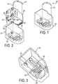
Fig. 1 is a perspective view of an exemplary diaphragm pump assembly according to the invention. -
Fig. 2 is an exploded perspective view of the diaphragm pump assembly, showing an exemplary noise mitigation boot removed from a diaphragm pump. -
Fig. 3 is an enlarged perspective view showing internal features of the noise mitigation boot. -
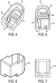
Fig. 4 is another perspective view of the noise mitigation boot. -
Fig. 5 is a plan view of the noise mitigation boot. -
Fig. 6 is another perspective view of the noise mitigation boot. -
Fig. 7 is an end elevational view of the noise mitigation boot. -
Fig. 8 is a transverse elevational view of the noise mitigation boot. -
Fig. 9 is still another perspective view of the noise mitigation boot. -
Fig. 10 is a bottom view of the noise mitigation boot. -
Fig. 11 is a bottom perspective view of the noise mitigation boot. -
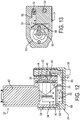
Fig. 12 is a vertical cross-sectional view of the diaphragm pump assembly taken along the line A-A ofFig. 15 , with the eccentric and diaphragm plunger removed. -
Fig. 13 is a horizontal cross-sectional view of the diaphragm pump assembly. -
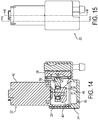
Fig. 14 is a vertical cross-sectional view taken along the line B-B ofFig. 15 , and showing the eccentric and diaphragm plunger. -
Fig. 15 is a side elevational view of the assembly. - In the discussion above and to follow, the terms "upper", "lower", "top", "bottom," "end," "inner," "left," "right," "level," "above," "below," "horizontal," "vertical," etc. refer to an exemplary diaphragm pump assembly oriented as shown in
Fig. 1 . These terms are used to reflect positional relationships with respect to the illustrated orientation and not to limit the diaphragm pump assembly to the illustrated orientation, as it will be appreciated the diaphragm pump assembly can be otherwise oriented. - Referring now in detail to
Figs. 1 and 2 , the exemplary diaphragm pump assembly is indicated generally byreference numeral 20. The diaphragm pump assembly comprises adiaphragm pump 22 and anoise mitigation boot 24 slipped over the diaphragm pump. - With additional reference to
Figs. 12 and 13 , thediaphragm pump 20 includes ahousing 28 having first andsecond ports interior chamber 34. Theinterior chamber 34 is divided by apumping diaphragm 36 into apumping chamber 38 and abackside chamber 40. The diaphragm may be of any suitable type and form, and typically will be formed of an elastomeric material although flexible metal diaphragms also could be used. In the illustrated diaphragm pump, the diaphragm is in the form of a generally planar sheet. - The
diaphragm pump 22 further includes amotor 42 for reciprocating the pumpingdiaphragm 36 for pumping air into and out of the pumpingchamber 38, and flowpassages second ports - In the illustrated embodiment, an electric rotary motor is used. The motor can be powered to drive an eccentric 48 that reciprocates a
plunger 50 back and forth for reciprocating the pumping diaphragm back and forth. This motion in one direction (intake/expansion stroke) increases the pumping chamber volume for drawing air into the pumping chamber via one of the flow passages. Motion in the reverse direction (outflow/compression stroke) forces the air out of the pumping chamber via the other of the flow passages. Theflow passages respective check valves - The
diaphragm pump 20 may be configured for use as either a vacuum pump or a pressure pump. In the illustrated embodiment, the diaphragm pump is configured for use as a vacuum pump. To this end, first (or intake)port 30 is configured for attachment to a vacuum flow line and the second (or exhaust)port 32 opens to an exterior surface of thehousing 28, such as the bottom surface 56 as best shown inFigs. 2 and12 . In particular, the first port is provided with atubular projection 58 that preferably is provided with at least one barb 60 for holding to the tubular projection a flow line that can be pushed onto the tubular projection. If used as a pressure pump, the exhaust port may be attached to a pressure flow line, and the intake port may draw in a fluid to be pumped. - The
check valves diaphragm 36, air is drawn in through theintake port 30 and during the outflow stroke the air in the expanded chamber is directed to theexhaust port 32. For use as a pressure pump, the check valves may be oppositely arranged. - As above mentioned, the
second port 32 opens to an exterior surface of the pump housing, such as the bottom surface 56 as best shown inFigs. 2 and12 . Thebackside chamber 38 also opens to an exterior surface of the pump housing, preferably at the same exterior surface 56 of the pump housing at anopening 62. - The
noise mitigation boot 24 has amuffler wall 64 overlying the exterior surface 56 of thehousing 28. The muffler wall has formed therein apassage 66 extending from thesecond port 32 to thebackside chamber 40 for effecting fluid communication between the second port and the backside chamber. Thepassage 66 forms a convoluted path, that has back and forth sections, which may be separated bybaffle walls 68, to form a serpentine path. The passage may have a minimum cross-sectional area equal or greater than the cross-sectional area of thesecond port 32, although smaller cross-sectional areas are possible. - As shown, the
passage 66 is formed by agroove 70 in an interior surface of themuffler wall 64 that is in juxtaposition with the exterior surface 56 of the housing. One end of the groove communicates with thesecond port 32 and the other end communicates with thebackside chamber 40. In particular, the groove at one end overlaps the second port and at the other end overlaps the backside chamber opening. Preferably, a plurality of the back and forth sections of the serpentine groove communicate directly with the backside chamber. - Hence, the
muffler wall 64 and more generally thenoise mitigation boot 24 provides pneumatic communication between thesecond port 32 and the backside chamber behind the pumping diaphragm. This is shown by the dashed lines inFigs 12 and 13 . This functions to reduce pneumatic noise. In particular, the exhaust air assists the compression stroke of the pump and is essentially idle during the expansion stroke. The pneumatic communication isolates pneumatic pumping noise with little performance impact. When the pump is used as a pressure pump, the reverse is true with air pulses being substantially cancelled. - The
noise mitigation boot 24 preferably is made of an elastomeric material, in particular butyl or chloroprene rubber, that can have a Shore A durometer hardness of between 40 and 80, preferably between 50 and 70, and more preferably between 55 and 65. Themuffler wall 64 preferably is pressed flush with the exterior surface such that the exterior surface closes the topside of the serpentine groove. - As best shown in
Figs. 3-11 , thenoise mitigation boot 24 can have a plurality of side walls 76-79 joined to the muffler wall. The side walls can have interior surfaces pressed flush with respective exterior surfaces of thehousing 22. The side walls preferably are stretched around the side walls of the housing for holding the noise mitigation boot on the housing. The noise mitigation boot can form a seal around the perimeter of the pump, although some infiltration of air between the noise mitigation boot and the housing is provided for efficient operation of the pump. At least one exhaust vent 80 (Fig. 14 ) can be provided in the noise mitigation boot for allowing the infiltration of air into the interior of the boot for communication with the backside chamber. Otherwise, the boot preferably fits tightly around the pump housing for aiding pneumatic communication between the second port and the backside chamber and to help reduce mechanical noise transmitted through the housing that typically will be made of plastic. - Generally, the diaphragm pump, with the noise mitigation boot installed, may experience a reduction in flow from 0% to 30%, or from 1% to 20%, or more typically 2% to 10%. The pump may also experience an increase in power consumption from 0% to 30%, or from 1% to 20%, and more typically from 2% to 10%.
- The
noise mitigation boot 24 preferably has anopening 84 through which thetubular port extension 58 extends. The noise mitigation boot may be sealed around the tubular extension at the opening in the boot. - Although the illustrated boot has other walls in addition to the
muffler wall 64 for enabling attachment of the boot to the pump, the boot may consist of only the muffler wall that may be integrated into the pump assembly in any suitable manner. - Although the invention has been shown and described with respect to a certain embodiment or embodiments, it is obvious that equivalent alterations and modifications (falling within the scope of the appended claims) will occur to others skilled in the art upon the reading and understanding of this specification and the annexed drawings.
Claims (11)
- A diaphragm pump assembly (20) comprising:a diaphragm pump (22); anda noise mitigation boot (24) attached to the diaphragm pump, the noise mitigation boot including a muffler wall (64) disposed on at least one side of the diaphragm pump;wherein the diaphragm pump includes a housing (28) having first and second ports (30, 32) and an interior chamber (34), a pumping diaphragm (36) disposed in the interior chamber and dividing the interior chamber into a pumping chamber (38) and a backside chamber (40), a motor (42) for reciprocating the pumping diaphragm for pumping air into and out of the pumping chamber, and flow passages (44, 46) connecting the pumping chamber to the first and second ports,wherein the second port (32) opens to an exterior surface (56) of the housing;wherein the muffler wall overlies the exterior surface of the housing, the wall having formed therein a passage (66) extending from the second port (32) to the backside chamber (40) for effecting fluid communication between the second port and the backside chamber;characterised in that:the passage (66) is formed by a groove (70) in an interior surface of the muffler wall (64) that is in juxtaposition with the exterior surface (56) of the housing;the groove has a serpentine shape including back and forth sections; andthe backside chamber (40) opens, at an end thereof opposite the pumping diaphragm (36), to the exterior surface of the housing at an opening, and the groove has a portion thereof overlapped by the opening.
- The diaphragm pump assembly of claim 1, wherein the first port (30) is configured for attachment to a flow line.
- The diaphragm pump assembly of claim 1, wherein a plurality of the back and forth sections communicate directly with the backside chamber.
- The diaphragm pump assembly of any preceding claim, wherein the noise mitigation boot is made of an elastomeric material.
- The diaphragm pump assembly of claim 4, wherein the elastomeric material, in particular butyl or chloroprene rubber, has a Shore A durometer hardness of between 40 and 80, and preferably between 50 and 70, and more preferably between 55 and 65.
- The diaphragm pump assembly of any preceding claim, wherein the muffler wall is pressed flush with the exterior surface.
- The diaphragm pump assembly of any preceding claim, wherein the noise mitigation boot has a plurality of side walls (76-79) joined to the muffler wall, and the side walls have interior surfaces pressed flush with respective exterior surfaces of the housing.
- The diaphragm pump assembly of claim 7, wherein the side walls are stretched around the side walls of the housing for holding the noise mitigation boot on the housing.
- The diaphragm pump assembly of claim 7 or 8, wherein the noise mitigation boot forms a seal around the perimeter of the pump but still allows some infiltration of air between the noise mitigation boot and the housing.
- The diaphragm pump assembly of claim 9, wherein at least one exhaust vent (80) is provided in the noise mitigation boot for allowing the infiltration of air into the interior of the boot for communication with the backside chamber.
- The diaphragm pump assembly of any preceding claim, wherein the first port has a tubular extension (58), preferably provided with a barb (60), projecting from the housing and though an opening in the noise mitigation boot that is sealed around the tubular extension.
Applications Claiming Priority (2)
| Application Number | Priority Date | Filing Date | Title |
|---|---|---|---|
| US201562156962P | 2015-05-05 | 2015-05-05 | |
| PCT/US2016/030917 WO2016179360A1 (en) | 2015-05-05 | 2016-05-05 | Miniature vacuum/pressure diaphragm pumps with noise mitigation boot |
Publications (2)
| Publication Number | Publication Date |
|---|---|
| EP3292304A1 EP3292304A1 (en) | 2018-03-14 |
| EP3292304B1 true EP3292304B1 (en) | 2020-12-09 |
Family
ID=56008874
Family Applications (1)
| Application Number | Title | Priority Date | Filing Date |
|---|---|---|---|
| EP16723219.8A Not-in-force EP3292304B1 (en) | 2015-05-05 | 2016-05-05 | Miniature vacuum/pressure diaphragm pumps with noise mitigation boot |
Country Status (5)
| Country | Link |
|---|---|
| US (1) | US10794375B2 (en) |
| EP (1) | EP3292304B1 (en) |
| CA (1) | CA2984613C (en) |
| MX (1) | MX2017014137A (en) |
| WO (1) | WO2016179360A1 (en) |
Families Citing this family (6)
| Publication number | Priority date | Publication date | Assignee | Title |
|---|---|---|---|---|
| CN109751229A (en) * | 2019-03-07 | 2019-05-14 | 宁波强生电机有限公司 | Modular booster pump |
| US12247562B2 (en) | 2019-11-01 | 2025-03-11 | Leggett & Platt Canada Co. | Pump noise attenuator and method thereof |
| EP4051904A4 (en) * | 2019-11-01 | 2024-01-31 | Leggett & Platt Canada Co. | PUMP NOISE ATTENUATOR AND METHOD THEREFOR |
| CN110726280A (en) * | 2019-11-20 | 2020-01-24 | 海信(山东)冰箱有限公司 | Low-temperature storage device |
| EP3915601A1 (en) * | 2020-05-25 | 2021-12-01 | Mölnlycke Health Care AB | Mobile negative pressure wound therapy device with reduced pump noise |
| CN114001012B (en) * | 2021-11-09 | 2023-05-30 | 山东凯恩真空技术有限公司 | Improved vacuum pump filtering device |
Citations (1)
| Publication number | Priority date | Publication date | Assignee | Title |
|---|---|---|---|---|
| US6007307A (en) * | 1996-11-26 | 1999-12-28 | Fujikin Incorporated | Air pump with noise reduction partitions in the housing |
Family Cites Families (18)
| Publication number | Priority date | Publication date | Assignee | Title |
|---|---|---|---|---|
| US3877842A (en) * | 1970-01-21 | 1975-04-15 | Itt | Air pumps |
| GB1354037A (en) * | 1971-06-01 | 1974-06-05 | Becker E | Diaphragm pumps |
| WO1987003650A1 (en) | 1985-12-11 | 1987-06-18 | Saggers Michael J | Improvements in vibratory diaphragm pumps |
| US5232353A (en) * | 1992-01-06 | 1993-08-03 | Grant Benton H | Pressurized diaphragm pump and directional flow controller therefor |
| GB9304445D0 (en) * | 1993-03-04 | 1993-04-21 | Wabco Automotive Uk | Vacuum pumps |
| US5731556A (en) | 1996-09-30 | 1998-03-24 | Ingersoll-Rand Company | Muffler for pneumatic device |
| WO2000048548A1 (en) | 1999-02-18 | 2000-08-24 | Koninklijke Philips Electronics N.V. | Vacuum massaging apparatus having a pump and having noise reduction means in the pump area |
| US6257842B1 (en) * | 1999-11-17 | 2001-07-10 | Techno Takatsuki Co., Ltd. | Silencer and electromagnetic vibrating type pump employing the same |
| PT1299648E (en) * | 2000-07-13 | 2012-03-20 | Electromed Inc | Body pulsating apparatus |
| US6485270B2 (en) * | 2001-02-22 | 2002-11-26 | Meiko Pet Corporation | Air pump with noise silence arrangement |
| US6644263B2 (en) * | 2001-12-04 | 2003-11-11 | Nicholas S. Hare | Engine with dry sump lubrication |
| DE10212239A1 (en) * | 2002-03-19 | 2003-10-09 | Knf Neuberger Gmbh | pump |
| US20040123247A1 (en) | 2002-12-20 | 2004-06-24 | Optimost Llc | Method and apparatus for dynamically altering electronic content |
| US20060034711A1 (en) * | 2004-08-13 | 2006-02-16 | Bergner Jeffrey W | Linear pump with sound attenuator |
| TWM292016U (en) | 2006-01-06 | 2006-06-11 | Tricore Corp | Air pump with reduced sound produced during air passage |
| DE202006006042U1 (en) * | 2006-04-13 | 2006-06-22 | Meiko Pet Corp., Ta Li | Aquarium pump, within a dome cap forming a housing, has an acoustic chamber at the outer side of its base with separate air sections interconnected by air holes to reduce noise emissions |
| DE102010009670B4 (en) | 2010-02-27 | 2013-09-19 | Knf Neuberger Gmbh | diaphragm pump |
| US9162004B1 (en) * | 2014-04-22 | 2015-10-20 | Prolitec Inc. | Removable cartridge for liquid diffusion device and cartridge insert thereof |
-
2016
- 2016-05-05 CA CA2984613A patent/CA2984613C/en active Active
- 2016-05-05 WO PCT/US2016/030917 patent/WO2016179360A1/en not_active Ceased
- 2016-05-05 EP EP16723219.8A patent/EP3292304B1/en not_active Not-in-force
- 2016-05-05 US US15/567,192 patent/US10794375B2/en not_active Expired - Fee Related
- 2016-05-05 MX MX2017014137A patent/MX2017014137A/en unknown
Patent Citations (1)
| Publication number | Priority date | Publication date | Assignee | Title |
|---|---|---|---|---|
| US6007307A (en) * | 1996-11-26 | 1999-12-28 | Fujikin Incorporated | Air pump with noise reduction partitions in the housing |
Also Published As
| Publication number | Publication date |
|---|---|
| EP3292304A1 (en) | 2018-03-14 |
| US20180135615A1 (en) | 2018-05-17 |
| CA2984613A1 (en) | 2016-11-10 |
| US10794375B2 (en) | 2020-10-06 |
| MX2017014137A (en) | 2018-03-15 |
| CA2984613C (en) | 2023-06-20 |
| WO2016179360A1 (en) | 2016-11-10 |
Similar Documents
| Publication | Publication Date | Title |
|---|---|---|
| CA2984613C (en) | Miniature vacuum/pressure diaphragm pumps with noise mitigation boot | |
| JP6625103B2 (en) | Pump cassette | |
| US7029245B2 (en) | Blood pumping unit, with a coplanar disk inlet valve and an annular outlet valve | |
| KR101386477B1 (en) | Noise reducing device for hermetic type compressor | |
| US20200318771A1 (en) | Fluid apparatus and buffer tank for use therein | |
| US9885348B2 (en) | Reciprocation pump and a dialysis apparatus equipped with the reciprocation pump | |
| EP1396637A3 (en) | Double diaphragm pump including spool valve air motor | |
| WO2016173457A1 (en) | Air valve, integrated air pump and wearable electronic sphygmomanometer | |
| CN222376673U (en) | Piezoelectric micropump | |
| CN118327943A (en) | A piezoelectric micro pump | |
| CN215805090U (en) | Pump head and pump valve integrated structure comprising same | |
| CN216812959U (en) | leak valve | |
| IL271629B1 (en) | Assembling a pump with a double-action reciprocating drive that can be used once | |
| CN215762157U (en) | Shock absorption diaphragm pump | |
| JP3103722B2 (en) | Fluid pump | |
| CN210068448U (en) | Gas diaphragm pump | |
| CN109838372B (en) | Gas diaphragm pump | |
| KR100273421B1 (en) | Oil supply of linear compressor | |
| CN216975183U (en) | Micropump and diaphragm device thereof | |
| KR102609582B1 (en) | Daiaphragm pump for suction device | |
| IL271644B1 (en) | Using balloon as damper for port of a reciprocating pump | |
| CN223529428U (en) | Passive exhaust valve and air pump for sphygmomanometer with such exhaust valve | |
| JP3770950B2 (en) | Diaphragm pump | |
| CN110318988B (en) | Diaphragm pump | |
| JP2004156514A (en) | Diaphragm pump |
Legal Events
| Date | Code | Title | Description |
|---|---|---|---|
| STAA | Information on the status of an ep patent application or granted ep patent |
Free format text: STATUS: THE INTERNATIONAL PUBLICATION HAS BEEN MADE |
|
| PUAI | Public reference made under article 153(3) epc to a published international application that has entered the european phase |
Free format text: ORIGINAL CODE: 0009012 |
|
| STAA | Information on the status of an ep patent application or granted ep patent |
Free format text: STATUS: REQUEST FOR EXAMINATION WAS MADE |
|
| 17P | Request for examination filed |
Effective date: 20171114 |
|
| AK | Designated contracting states |
Kind code of ref document: A1 Designated state(s): AL AT BE BG CH CY CZ DE DK EE ES FI FR GB GR HR HU IE IS IT LI LT LU LV MC MK MT NL NO PL PT RO RS SE SI SK SM TR |
|
| AX | Request for extension of the european patent |
Extension state: BA ME |
|
| DAV | Request for validation of the european patent (deleted) | ||
| DAX | Request for extension of the european patent (deleted) | ||
| STAA | Information on the status of an ep patent application or granted ep patent |
Free format text: STATUS: EXAMINATION IS IN PROGRESS |
|
| 17Q | First examination report despatched |
Effective date: 20181128 |
|
| RAP1 | Party data changed (applicant data changed or rights of an application transferred) |
Owner name: PARKER HANNIFIN CORPORATION |
|
| RAP1 | Party data changed (applicant data changed or rights of an application transferred) |
Owner name: PARKER-HANNIFIN CORPORATION |
|
| GRAP | Despatch of communication of intention to grant a patent |
Free format text: ORIGINAL CODE: EPIDOSNIGR1 |
|
| STAA | Information on the status of an ep patent application or granted ep patent |
Free format text: STATUS: GRANT OF PATENT IS INTENDED |
|
| RIC1 | Information provided on ipc code assigned before grant |
Ipc: F04B 45/04 20060101ALI20200513BHEP Ipc: F04B 45/047 20060101ALN20200513BHEP Ipc: F04B 39/14 20060101ALI20200513BHEP Ipc: F04B 39/00 20060101AFI20200513BHEP |
|
| RIC1 | Information provided on ipc code assigned before grant |
Ipc: F04B 45/04 20060101ALI20200520BHEP Ipc: F04B 39/14 20060101ALI20200520BHEP Ipc: F04B 39/00 20060101AFI20200520BHEP Ipc: F04B 45/047 20060101ALN20200520BHEP |
|
| INTG | Intention to grant announced |
Effective date: 20200610 |
|
| GRAJ | Information related to disapproval of communication of intention to grant by the applicant or resumption of examination proceedings by the epo deleted |
Free format text: ORIGINAL CODE: EPIDOSDIGR1 |
|
| STAA | Information on the status of an ep patent application or granted ep patent |
Free format text: STATUS: EXAMINATION IS IN PROGRESS |
|
| GRAR | Information related to intention to grant a patent recorded |
Free format text: ORIGINAL CODE: EPIDOSNIGR71 |
|
| GRAS | Grant fee paid |
Free format text: ORIGINAL CODE: EPIDOSNIGR3 |
|
| STAA | Information on the status of an ep patent application or granted ep patent |
Free format text: STATUS: GRANT OF PATENT IS INTENDED |
|
| INTC | Intention to grant announced (deleted) | ||
| RIC1 | Information provided on ipc code assigned before grant |
Ipc: F04B 39/00 20060101AFI20200929BHEP Ipc: F04B 45/047 20060101ALN20200929BHEP Ipc: F04B 39/14 20060101ALI20200929BHEP Ipc: F04B 45/04 20060101ALI20200929BHEP |
|
| GRAA | (expected) grant |
Free format text: ORIGINAL CODE: 0009210 |
|
| STAA | Information on the status of an ep patent application or granted ep patent |
Free format text: STATUS: THE PATENT HAS BEEN GRANTED |
|
| INTG | Intention to grant announced |
Effective date: 20201020 |
|
| AK | Designated contracting states |
Kind code of ref document: B1 Designated state(s): AL AT BE BG CH CY CZ DE DK EE ES FI FR GB GR HR HU IE IS IT LI LT LU LV MC MK MT NL NO PL PT RO RS SE SI SK SM TR |
|
| REG | Reference to a national code |
Ref country code: GB Ref legal event code: FG4D |
|
| REG | Reference to a national code |
Ref country code: AT Ref legal event code: REF Ref document number: 1343722 Country of ref document: AT Kind code of ref document: T Effective date: 20201215 Ref country code: CH Ref legal event code: EP |
|
| REG | Reference to a national code |
Ref country code: DE Ref legal event code: R096 Ref document number: 602016049396 Country of ref document: DE |
|
| REG | Reference to a national code |
Ref country code: IE Ref legal event code: FG4D |
|
| PG25 | Lapsed in a contracting state [announced via postgrant information from national office to epo] |
Ref country code: RS Free format text: LAPSE BECAUSE OF FAILURE TO SUBMIT A TRANSLATION OF THE DESCRIPTION OR TO PAY THE FEE WITHIN THE PRESCRIBED TIME-LIMIT Effective date: 20201209 Ref country code: NO Free format text: LAPSE BECAUSE OF FAILURE TO SUBMIT A TRANSLATION OF THE DESCRIPTION OR TO PAY THE FEE WITHIN THE PRESCRIBED TIME-LIMIT Effective date: 20210309 Ref country code: FI Free format text: LAPSE BECAUSE OF FAILURE TO SUBMIT A TRANSLATION OF THE DESCRIPTION OR TO PAY THE FEE WITHIN THE PRESCRIBED TIME-LIMIT Effective date: 20201209 Ref country code: GR Free format text: LAPSE BECAUSE OF FAILURE TO SUBMIT A TRANSLATION OF THE DESCRIPTION OR TO PAY THE FEE WITHIN THE PRESCRIBED TIME-LIMIT Effective date: 20210310 |
|
| REG | Reference to a national code |
Ref country code: AT Ref legal event code: MK05 Ref document number: 1343722 Country of ref document: AT Kind code of ref document: T Effective date: 20201209 |
|
| PG25 | Lapsed in a contracting state [announced via postgrant information from national office to epo] |
Ref country code: SE Free format text: LAPSE BECAUSE OF FAILURE TO SUBMIT A TRANSLATION OF THE DESCRIPTION OR TO PAY THE FEE WITHIN THE PRESCRIBED TIME-LIMIT Effective date: 20201209 Ref country code: BG Free format text: LAPSE BECAUSE OF FAILURE TO SUBMIT A TRANSLATION OF THE DESCRIPTION OR TO PAY THE FEE WITHIN THE PRESCRIBED TIME-LIMIT Effective date: 20210309 Ref country code: LV Free format text: LAPSE BECAUSE OF FAILURE TO SUBMIT A TRANSLATION OF THE DESCRIPTION OR TO PAY THE FEE WITHIN THE PRESCRIBED TIME-LIMIT Effective date: 20201209 |
|
| REG | Reference to a national code |
Ref country code: NL Ref legal event code: MP Effective date: 20201209 |
|
| PG25 | Lapsed in a contracting state [announced via postgrant information from national office to epo] |
Ref country code: NL Free format text: LAPSE BECAUSE OF FAILURE TO SUBMIT A TRANSLATION OF THE DESCRIPTION OR TO PAY THE FEE WITHIN THE PRESCRIBED TIME-LIMIT Effective date: 20201209 Ref country code: HR Free format text: LAPSE BECAUSE OF FAILURE TO SUBMIT A TRANSLATION OF THE DESCRIPTION OR TO PAY THE FEE WITHIN THE PRESCRIBED TIME-LIMIT Effective date: 20201209 |
|
| REG | Reference to a national code |
Ref country code: LT Ref legal event code: MG9D |
|
| PG25 | Lapsed in a contracting state [announced via postgrant information from national office to epo] |
Ref country code: PT Free format text: LAPSE BECAUSE OF FAILURE TO SUBMIT A TRANSLATION OF THE DESCRIPTION OR TO PAY THE FEE WITHIN THE PRESCRIBED TIME-LIMIT Effective date: 20210409 Ref country code: SK Free format text: LAPSE BECAUSE OF FAILURE TO SUBMIT A TRANSLATION OF THE DESCRIPTION OR TO PAY THE FEE WITHIN THE PRESCRIBED TIME-LIMIT Effective date: 20201209 Ref country code: RO Free format text: LAPSE BECAUSE OF FAILURE TO SUBMIT A TRANSLATION OF THE DESCRIPTION OR TO PAY THE FEE WITHIN THE PRESCRIBED TIME-LIMIT Effective date: 20201209 Ref country code: LT Free format text: LAPSE BECAUSE OF FAILURE TO SUBMIT A TRANSLATION OF THE DESCRIPTION OR TO PAY THE FEE WITHIN THE PRESCRIBED TIME-LIMIT Effective date: 20201209 Ref country code: SM Free format text: LAPSE BECAUSE OF FAILURE TO SUBMIT A TRANSLATION OF THE DESCRIPTION OR TO PAY THE FEE WITHIN THE PRESCRIBED TIME-LIMIT Effective date: 20201209 Ref country code: CZ Free format text: LAPSE BECAUSE OF FAILURE TO SUBMIT A TRANSLATION OF THE DESCRIPTION OR TO PAY THE FEE WITHIN THE PRESCRIBED TIME-LIMIT Effective date: 20201209 Ref country code: EE Free format text: LAPSE BECAUSE OF FAILURE TO SUBMIT A TRANSLATION OF THE DESCRIPTION OR TO PAY THE FEE WITHIN THE PRESCRIBED TIME-LIMIT Effective date: 20201209 |
|
| PG25 | Lapsed in a contracting state [announced via postgrant information from national office to epo] |
Ref country code: AT Free format text: LAPSE BECAUSE OF FAILURE TO SUBMIT A TRANSLATION OF THE DESCRIPTION OR TO PAY THE FEE WITHIN THE PRESCRIBED TIME-LIMIT Effective date: 20201209 Ref country code: PL Free format text: LAPSE BECAUSE OF FAILURE TO SUBMIT A TRANSLATION OF THE DESCRIPTION OR TO PAY THE FEE WITHIN THE PRESCRIBED TIME-LIMIT Effective date: 20201209 |
|
| REG | Reference to a national code |
Ref country code: DE Ref legal event code: R097 Ref document number: 602016049396 Country of ref document: DE |
|
| PG25 | Lapsed in a contracting state [announced via postgrant information from national office to epo] |
Ref country code: IS Free format text: LAPSE BECAUSE OF FAILURE TO SUBMIT A TRANSLATION OF THE DESCRIPTION OR TO PAY THE FEE WITHIN THE PRESCRIBED TIME-LIMIT Effective date: 20210409 |
|
| PLBE | No opposition filed within time limit |
Free format text: ORIGINAL CODE: 0009261 |
|
| STAA | Information on the status of an ep patent application or granted ep patent |
Free format text: STATUS: NO OPPOSITION FILED WITHIN TIME LIMIT |
|
| PG25 | Lapsed in a contracting state [announced via postgrant information from national office to epo] |
Ref country code: IT Free format text: LAPSE BECAUSE OF FAILURE TO SUBMIT A TRANSLATION OF THE DESCRIPTION OR TO PAY THE FEE WITHIN THE PRESCRIBED TIME-LIMIT Effective date: 20201209 Ref country code: AL Free format text: LAPSE BECAUSE OF FAILURE TO SUBMIT A TRANSLATION OF THE DESCRIPTION OR TO PAY THE FEE WITHIN THE PRESCRIBED TIME-LIMIT Effective date: 20201209 |
|
| 26N | No opposition filed |
Effective date: 20210910 |
|
| PG25 | Lapsed in a contracting state [announced via postgrant information from national office to epo] |
Ref country code: DK Free format text: LAPSE BECAUSE OF FAILURE TO SUBMIT A TRANSLATION OF THE DESCRIPTION OR TO PAY THE FEE WITHIN THE PRESCRIBED TIME-LIMIT Effective date: 20201209 Ref country code: SI Free format text: LAPSE BECAUSE OF FAILURE TO SUBMIT A TRANSLATION OF THE DESCRIPTION OR TO PAY THE FEE WITHIN THE PRESCRIBED TIME-LIMIT Effective date: 20201209 |
|
| REG | Reference to a national code |
Ref country code: CH Ref legal event code: PL |
|
| PG25 | Lapsed in a contracting state [announced via postgrant information from national office to epo] |
Ref country code: CH Free format text: LAPSE BECAUSE OF NON-PAYMENT OF DUE FEES Effective date: 20210531 Ref country code: LU Free format text: LAPSE BECAUSE OF NON-PAYMENT OF DUE FEES Effective date: 20210505 Ref country code: MC Free format text: LAPSE BECAUSE OF FAILURE TO SUBMIT A TRANSLATION OF THE DESCRIPTION OR TO PAY THE FEE WITHIN THE PRESCRIBED TIME-LIMIT Effective date: 20201209 Ref country code: LI Free format text: LAPSE BECAUSE OF NON-PAYMENT OF DUE FEES Effective date: 20210531 Ref country code: ES Free format text: LAPSE BECAUSE OF FAILURE TO SUBMIT A TRANSLATION OF THE DESCRIPTION OR TO PAY THE FEE WITHIN THE PRESCRIBED TIME-LIMIT Effective date: 20201209 |
|
| REG | Reference to a national code |
Ref country code: BE Ref legal event code: MM Effective date: 20210531 |
|
| PG25 | Lapsed in a contracting state [announced via postgrant information from national office to epo] |
Ref country code: IE Free format text: LAPSE BECAUSE OF NON-PAYMENT OF DUE FEES Effective date: 20210505 |
|
| PG25 | Lapsed in a contracting state [announced via postgrant information from national office to epo] |
Ref country code: IS Free format text: LAPSE BECAUSE OF FAILURE TO SUBMIT A TRANSLATION OF THE DESCRIPTION OR TO PAY THE FEE WITHIN THE PRESCRIBED TIME-LIMIT Effective date: 20210409 Ref country code: FR Free format text: LAPSE BECAUSE OF NON-PAYMENT OF DUE FEES Effective date: 20210531 |
|
| PG25 | Lapsed in a contracting state [announced via postgrant information from national office to epo] |
Ref country code: BE Free format text: LAPSE BECAUSE OF NON-PAYMENT OF DUE FEES Effective date: 20210531 |
|
| PG25 | Lapsed in a contracting state [announced via postgrant information from national office to epo] |
Ref country code: HU Free format text: LAPSE BECAUSE OF FAILURE TO SUBMIT A TRANSLATION OF THE DESCRIPTION OR TO PAY THE FEE WITHIN THE PRESCRIBED TIME-LIMIT; INVALID AB INITIO Effective date: 20160505 |
|
| P01 | Opt-out of the competence of the unified patent court (upc) registered |
Effective date: 20230524 |
|
| PG25 | Lapsed in a contracting state [announced via postgrant information from national office to epo] |
Ref country code: CY Free format text: LAPSE BECAUSE OF FAILURE TO SUBMIT A TRANSLATION OF THE DESCRIPTION OR TO PAY THE FEE WITHIN THE PRESCRIBED TIME-LIMIT Effective date: 20201209 |
|
| PGFP | Annual fee paid to national office [announced via postgrant information from national office to epo] |
Ref country code: DE Payment date: 20230530 Year of fee payment: 8 |
|
| PGFP | Annual fee paid to national office [announced via postgrant information from national office to epo] |
Ref country code: GB Payment date: 20230529 Year of fee payment: 8 |
|
| PG25 | Lapsed in a contracting state [announced via postgrant information from national office to epo] |
Ref country code: MK Free format text: LAPSE BECAUSE OF FAILURE TO SUBMIT A TRANSLATION OF THE DESCRIPTION OR TO PAY THE FEE WITHIN THE PRESCRIBED TIME-LIMIT Effective date: 20201209 |
|
| PG25 | Lapsed in a contracting state [announced via postgrant information from national office to epo] |
Ref country code: TR Free format text: LAPSE BECAUSE OF FAILURE TO SUBMIT A TRANSLATION OF THE DESCRIPTION OR TO PAY THE FEE WITHIN THE PRESCRIBED TIME-LIMIT Effective date: 20201209 |
|
| PG25 | Lapsed in a contracting state [announced via postgrant information from national office to epo] |
Ref country code: MT Free format text: LAPSE BECAUSE OF FAILURE TO SUBMIT A TRANSLATION OF THE DESCRIPTION OR TO PAY THE FEE WITHIN THE PRESCRIBED TIME-LIMIT Effective date: 20201209 |
|
| REG | Reference to a national code |
Ref country code: DE Ref legal event code: R119 Ref document number: 602016049396 Country of ref document: DE |
|
| GBPC | Gb: european patent ceased through non-payment of renewal fee |
Effective date: 20240505 |
|
| PG25 | Lapsed in a contracting state [announced via postgrant information from national office to epo] |
Ref country code: DE Free format text: LAPSE BECAUSE OF NON-PAYMENT OF DUE FEES Effective date: 20241203 |
|
| PG25 | Lapsed in a contracting state [announced via postgrant information from national office to epo] |
Ref country code: GB Free format text: LAPSE BECAUSE OF NON-PAYMENT OF DUE FEES Effective date: 20240505 |