EP3291466A1 - Electronic device and method - Google Patents
Electronic device and method Download PDFInfo
- Publication number
- EP3291466A1 EP3291466A1 EP16186939.1A EP16186939A EP3291466A1 EP 3291466 A1 EP3291466 A1 EP 3291466A1 EP 16186939 A EP16186939 A EP 16186939A EP 3291466 A1 EP3291466 A1 EP 3291466A1
- Authority
- EP
- European Patent Office
- Prior art keywords
- signal strength
- antenna
- movable
- electronic device
- calibration
- Prior art date
- Legal status (The legal status is an assumption and is not a legal conclusion. Google has not performed a legal analysis and makes no representation as to the accuracy of the status listed.)
- Granted
Links
Images




Classifications
-
- H—ELECTRICITY
- H04—ELECTRIC COMMUNICATION TECHNIQUE
- H04B—TRANSMISSION
- H04B17/00—Monitoring; Testing
- H04B17/20—Monitoring; Testing of receivers
- H04B17/27—Monitoring; Testing of receivers for locating or positioning the transmitter
-
- H—ELECTRICITY
- H04—ELECTRIC COMMUNICATION TECHNIQUE
- H04B—TRANSMISSION
- H04B17/00—Monitoring; Testing
- H04B17/30—Monitoring; Testing of propagation channels
- H04B17/309—Measuring or estimating channel quality parameters
- H04B17/318—Received signal strength
Definitions
- the invention relates to an electronic device for wirelessly transmitting and receiving data and a respective method.
- Modern electronic consumer devices communicate digital data over different channels, like e.g. wired networks or wireless networks.
- wireless data transmission systems like e.g. Wi-Fi or Bluetooth
- the quality of signal reception depends on a plurality of different factors, which are mostly external to the respective device.
- the consumer devices usually comprise an internal antenna, which is fixed to a certain position. Further, the devices cannot influence the external factors, which can further change continually. Therefore, with the changing external factors e.g. the speed of data transmission, and the stability of the connection also change continuously.
- the present invention provides an electronic device with the features of claim 1 and a method with the features of claim 8.
- an electronic device for wirelessly transmitting and receiving data comprises a movable antenna, which is controllably movable in at least one direction, and a calibration controller, which is configured to control in a calibration phase the antenna to move to a plurality of different positions and to measure the signal strength of a received signal at the different positions. Further, after moving the antenna to the plurality of different positions the calibration controller is further configured to position in a data communication phase the antenna at the position with the highest measured signal strength.
- a method for wirelessly transmitting and receiving data comprises controlling in a calibration phase a movable antenna, which is controllably movable in at least one direction, to move to a plurality of different positions and to measure the signal strength of a received signal at the different positions, and positioning in a data communication phase the antenna at the position with the highest measured signal strength after moving the antenna to the plurality of different positions.
- a device comprises a fixed antenna
- the user can e.g. move the device, if it is a movable device, to improve the signal reception in the device.
- this is only practical in small devices, like e.g. Tablet-PCs or the like.
- the device is e.g. a smart TV set with a large screen, like e.g. a 65 inch screen, it is not practical any more to move the TV set to improve the signal quality.
- the present invention therefore parts from the base that the electronic consumer device should not be moved by the user to improve the signal quality.
- the present patent application provides the electronic device with a movable antenna. That means, that the antenna can be moved inside of e.g. a housing of the electronic device while the electronic device is in use. This movement of the antenna is controlled by the calibration controller according to the present invention.
- the calibration controller in a calibration phase moves the antenna to a plurality of different positions. After moving the antenna to the plurality of positions, the calibration controller will then determine the position with the best signal strength and move the antenna to that position for data transmission in a data transmission phase. It is understood, that during the calibration phase data communication can already be actively performed. The difference will only lay in the varying signal strength.
- the signal strength can e.g. be measured by the calibration controller.
- the signal processing elements in the electronic device can provide the calibration controller with the signal strength value.
- the present invention therefore allows optimizing wireless data transmissions in electronic devices by moving the antenna of the electronic device to the optimal position within the movement limits of the antenna.
- the present invention therefore makes obsolete e.g. external antennas or the like.
- the calibration controller can be configured to permanently monitor the signal strength of the received signal, and if the monitored signal strength is lower than a predetermined threshold below the most recent signal strength at the position with the highest measured signal strength, repeat the calibration phase and position the antenna at the new position with the highest measured signal strength. This means that the calibration controller will permanently monitor the signal strength of the received signal and perform a re-calibration if the signal strength drops below the threshold value. During re-calibration the signal transmission can continue. There is no need to interrupt the signal transmission while the antenna moves. This allows the calibration controller to take into account a changing environment and adapt the antenna position during normal operation of the electronic device.
- a time out can be defined in the calibration controller.
- the calibration controller can e.g. only perform a re-calibration, if the signal strength drops below the threshold value for a time as long as the time out.
- the movable antenna can comprise a movable mechanical support and an antenna element, which is coupled to the movable mechanical support.
- the antenna element can e.g. be mechanically fixed to the mechanical support by soldering, gluing, clamping or the like.
- the electric connection of the antenna element can be performed via the mechanical support, i.e. via traces or the like.
- the antenna element can be contacted via a cable.
- the antenna element can e.g. be a surface mounted antenna, a PCB antenna, which is e.g. formed of copper traces on a substrate, or any other kind of antenna.
- the mechanical support can comprise an electro mechanic drive, which is configured to translatably move the mechanical support in the at least two directions.
- An electro mechanic drive is very flexible and can be easily controlled.
- the electro mechanic drive can comprise for every direction of movement a linear electric motor and/or a rotating electric motor with a spindle mechanic.
- Linear electric motors usually provide a mechanical support the moving object, in this case the antenna element. Therefore, with linear electric motors the mechanical structure can be provided with reduced complexity.
- the use of a rotating electric motor with a spindle mechanic provides a more flexible mechanic arrangement.
- a separate motor can be provided for different directions of movement, which can e.g. be perpendicular to each other.
- the different driving units e.g. the linear electric motors, can then be stacked on top of each other.
- the electro mechanic drive can e.g. form a kind of x-y cross table.
- the electro mechanic drive can comprise a movement guide with a spirally shaped opening and is configured to move the antenna element in two axis by rotating the mechanical support with the antenna element being placed in the spirally shaped opening.
- the movement guide can also be called a sliding block guide, since a block, which supports the antenna element moves in the spirally shaped opening. This allows moving the antenna in a plane with only the rotation of a single motor.
- the electro mechanic drive can comprise MEMS drives or any other electromechanical arrangement, which can move the antenna element in at least one direction.
- the calibration controller in the calibration phase or during re-calibration can be configured to move the antenna to the maximum position in every one of the directions and record the signal strength for a plurality of positions between the maximum positions. Further, the calibration controller can be configured to select the position of the antenna in the communication phase based on the recorded signal strengths.
- the controller can e.g. record the signal strengths in an array, where the array index refers to a specific position, i.e. every position is identified by a number, which is equal to the index of the respective cell/position of the array. Identifying the position with the highest signal strength can then simply be performed by identifying the array index with the highest recorded value.
- the electronic device 1 of Fig. 1 comprises a movable antenna 2, which is connected to the calibration controller 3.
- the electronic device 1 further comprises a signal processing unit 9, which performs the regular signal processing for receiving wireless signals 7 in and transmitting wireless signals from the electronic device 1.
- the movable antenna 2 is movable in two directions 4, 5, which are perpendicular to each other.
- the movement of the antenna 2 can be controlled via control commands 6, which are generated by the calibration controller 3.
- position sensors which can sense the position of the movable antenna 2 and provide respective measurement values to the calibration controller 3. It is understood, that such position sensors are just optional and that a drive system can be used, which comprises inherent positioning means. Such a drive system can e.g. use stepper motors, where the movement per step is known.
- the calibration controller 3 is further configured to evaluate the signal strength 8, also called RSSI (Received Signal Strength Indicator) of the received wireless signal 7.
- the movable antenna 2 can e.g. comprise signal processing elements, which determine the signal strength 8.
- the calibration controller 3 can determine the signal strength 8 based on the received signal 7, which can be provided by the movable antenna 2.
- the signal processing unit 9 can provide the calibration controller 3 with the signal strength 8.
- the calibration controller 3 will move the movable antenna 2 into a plurality of different positions within the range of movement of the movable antenna 2.
- the calibration controller 3 can e.g. perform a line-wise or column-wise scanning movement with the movable antenna 2.
- the calibration controller 3 will record the signal strengths 8 for the different positions of the movable antenna 2.
- the calibration controller 3 will determine the position of the movable antenna 2, at which the signal strength 8 is the highest. If the signal strength 8 is the highest at a certain position the quality and speed of the signal transmission will also be best at the respective position. Therefore, the calibration controller 3 will move the movable antenna 2 into the respective position for regular operation of the electronic device 1.
- the signal processing unit 9 can already start normal operation.
- the only difference to the normal operation or communication mode is that the signal strength 8 of the received signal 7 will vary at the signal processing unit 9.
- signal processing units 9 are usually configured to handle varying signal strengths, since this also happens in ordinary systems.
- the calibration controller 3 will not permanently move the movable antenna 2. Instead, the calibration controller 3 can optionally monitor the signal strength 8 in the normal operation mode, while the signal processing unit 9 performs the respective signal transmissions. Only if the signal strength drops below a predetermined threshold, the calibration controller 3 repeats the calibration, i.e. the moving of the movable antenna 2, the determining of the position of the highest signal strength and the final positioning.
- the threshold can e.g. be determined by subtracting a given value from the last determined maximum signal strength 8.
- Figs. 2 - 4 show exemplary embodiments of mechanical arrangements for moving the movable antenna 2.
- the electronic device 21 of Fig. 2 comprises a mechanical arrangement, which works like an x-y cross table.
- the arrangement comprises two perpendicular axis and an axis movement unit 37, 38 for every axis.
- Every axis movement unit 37, 38 comprises an electric motor 30, 32, which is functionally connected to a threaded rod 31, 32.
- a slide 34 is shown as an example of how to connect the threaded rod 31 to the moving element, in this case slide 34 of the antenna element 35.
- the axis movement unit 38 can be connected to the axis movement unit 37 in a similar way, i.e. one element of the axis movement unit 38 can comprise a thread, into which the threaded rod 33 of the axis movement unit 37 can be inserted.
- the electric motors 30 and 32 are controlled by the calibration controller 23, which generates respective control commands 26.
- the signal processing unit 29 is connected via a cable 36 to the antenna element 35.
- the signal processing unit 29 evaluates the received wireless signal 27 and provides the calibration controller 23 with the respective signal strength 28.
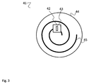
- Fig. 3 shows a top view of an alternate mechanical arrangement for moving the antenna element 43.
- a support plate 44 comprises a spiral-shaped guide 45.
- the spiral-shaped guide 45 is provided as a recess in the support plate 44.
- a slide 47 (see Fig. 4 ), which protrudes through the spiral-shaped guide 45 together with the antenna element 43 forms the movable antenna 42.
- Fig. 4 it can be seen that the slide 47 is positioned on a guide rod 48, which has no thread. Instead the slide 47 can freely glide on the guide rod 48.
- An electric motor 46 rotates the guide rod 48, such that the part of the slide 47 that protrudes through the support plate 44 will be guided by the spiral-shaped guide 45. That means that with every turn of the guide rod 48, the slide 47 will move to the next winding of the spiral-shaped guide 45. Therefore, depending on the direction of rotation of the guide rod 48, the antenna element 43 will move outwards or inwards.
- the arrangement of Figs. 3 and 4 can provide a two dimensional movement of the antenna element 43 with only one electric motor 46.
- Figs. 2 to 4 are just exemplary arrangements.
- Alternative arrangements can e.g. comprise a third direction of movement, i.e. elevation, or a rotation of the antenna element.
- Fig. 5 shows a flow diagram of an embodiment of a method for wirelessly transmitting and receiving data with an electronic device 1, 21, 41.
- the method comprises controlling S1 in a calibration phase a movable antenna 2, 22, 42, which is controllably movable in at least one direction 4, 5, 24.
- the controlling comprises moving the antenna 2, 22, 42 to a plurality of different positions and to measure the signal strength 8, 28 of a received signal 7, 27 at the different positions.
- the movable antenna 2, 22, 42 is positioned at the position with the highest measured signal strength 8, 28 after moving the movable antenna 2, 22, 42 to the plurality of different positions.
- the movable antenna 2, 22, 42 can e.g. be moved to the maximum position in every one of the directions 4, 5, 24. Further, the signal strength 8, 28 can be recorded for a plurality of positions between the maximum positions. E.g. a predetermined distance can be given for the different positions at which the signal strength 8, 28 is determined.
- the position of the movable antenna 2, 22, 42 in the communication phase, also normal operation phase, is then selected based on the recorded signal strengths 8, 28, especially on the maximum signal strength 8, 28.
- the method can further comprise permanently monitoring the signal strength 8, 28 of the received signal 7, 27, i.e. also during a normal operation mode of the electronic device 1, 21, 41. If the monitored signal strength 8, 28 is lower than or drops below a predetermined threshold below the most recent signal strength 8, 28 at the position with the highest measured signal strength 8, 28, the steps of controlling and positioning can be repeated. That means, that the calibration of the movable antenna 2, 22, 42 is repeated.
- a movable mechanical support 34, 47 can e.g. be moved, to which an antenna element 35, 43 is coupled.
- the mechanical support 34, 47 can e.g. be moved translatably or rotatably by an electro mechanic drive in the at least two directions 4, 5, 24.
- the electro mechanic drive can be provided for every direction 4, 5, 24 of movement with a linear electric motor 30, 32, 46 and/or a rotating electric motor 30, 32, 46 with a spindle mechanic.
- the electro mechanic drive can be provided with a movement guide 44 with a spirally shaped opening 45.
- the antenna element 35, 43 can then be moved in two axis by rotating the mechanical support 34, 47 with the antenna element 35, 43 being placed in the spirally shaped opening 45.
- the present invention provides an electronic device for wirelessly transmitting and receiving data.
- the device comprises a movable antenna, which is controllably movable in at least one direction, and a calibration controller, which is configured to control in a calibration phase the movable antenna to move to a plurality of different positions and to measure the signal strength of a received signal at the different positions. Further, after moving the movable antenna to the plurality of different positions the calibration controller is further configured to position in a data communication phase the movable antenna at the position with the highest measured signal strength.
- the present invention further provides a corresponding method.
Landscapes
- Engineering & Computer Science (AREA)
- Physics & Mathematics (AREA)
- Electromagnetism (AREA)
- Computer Networks & Wireless Communication (AREA)
- Signal Processing (AREA)
- Quality & Reliability (AREA)
- Variable-Direction Aerials And Aerial Arrays (AREA)
- Lock And Its Accessories (AREA)
Abstract
Description
- The invention relates to an electronic device for wirelessly transmitting and receiving data and a respective method.
- Although applicable to any system that uses wireless data transmission, the present patent application will mainly be described in conjunction with consumer electronic devices like e.g. TV sets, set-top boxes, printers, scanners and the like.
- Modern electronic consumer devices communicate digital data over different channels, like e.g. wired networks or wireless networks. Especially in wireless data transmission systems, like e.g. Wi-Fi or Bluetooth, the quality of signal reception depends on a plurality of different factors, which are mostly external to the respective device. The consumer devices usually comprise an internal antenna, which is fixed to a certain position. Further, the devices cannot influence the external factors, which can further change continually. Therefore, with the changing external factors e.g. the speed of data transmission, and the stability of the connection also change continuously.
- Accordingly, there is a need for an improved wireless data transmission in consumer devices.
- The present invention provides an electronic device with the features of
claim 1 and a method with the features ofclaim 8. - Accordingly, an electronic device for wirelessly transmitting and receiving data comprises a movable antenna, which is controllably movable in at least one direction, and a calibration controller, which is configured to control in a calibration phase the antenna to move to a plurality of different positions and to measure the signal strength of a received signal at the different positions. Further, after moving the antenna to the plurality of different positions the calibration controller is further configured to position in a data communication phase the antenna at the position with the highest measured signal strength.
- Further, a method for wirelessly transmitting and receiving data comprises controlling in a calibration phase a movable antenna, which is controllably movable in at least one direction, to move to a plurality of different positions and to measure the signal strength of a received signal at the different positions, and positioning in a data communication phase the antenna at the position with the highest measured signal strength after moving the antenna to the plurality of different positions.
- In the frequency range of wireless data transmissions in consumer devices, e.g. via Wi-Fi or Bluetooth, movements of the antenna in the range of millimeters or centimeters can have a huge impact on the signal quality and therefore on the speed of data transmission, and the stability of the connection.
- If a device comprises a fixed antenna, the user can e.g. move the device, if it is a movable device, to improve the signal reception in the device. However, this is only practical in small devices, like e.g. Tablet-PCs or the like. If the device is e.g. a smart TV set with a large screen, like e.g. a 65 inch screen, it is not practical any more to move the TV set to improve the signal quality.
- The present invention therefore parts from the base that the electronic consumer device should not be moved by the user to improve the signal quality. Instead, the present patent application provides the electronic device with a movable antenna. That means, that the antenna can be moved inside of e.g. a housing of the electronic device while the electronic device is in use. This movement of the antenna is controlled by the calibration controller according to the present invention.
- The calibration controller in a calibration phase moves the antenna to a plurality of different positions. After moving the antenna to the plurality of positions, the calibration controller will then determine the position with the best signal strength and move the antenna to that position for data transmission in a data transmission phase. It is understood, that during the calibration phase data communication can already be actively performed. The difference will only lay in the varying signal strength.
- The signal strength can e.g. be measured by the calibration controller. As an alternative, the signal processing elements in the electronic device can provide the calibration controller with the signal strength value.
- The present invention therefore allows optimizing wireless data transmissions in electronic devices by moving the antenna of the electronic device to the optimal position within the movement limits of the antenna. The present invention therefore makes obsolete e.g. external antennas or the like.
- Further embodiments of the present invention are subject of the further subclaims and of the following description, referring to the drawings.
- In one embodiment, the calibration controller can be configured to permanently monitor the signal strength of the received signal, and if the monitored signal strength is lower than a predetermined threshold below the most recent signal strength at the position with the highest measured signal strength, repeat the calibration phase and position the antenna at the new position with the highest measured signal strength. This means that the calibration controller will permanently monitor the signal strength of the received signal and perform a re-calibration if the signal strength drops below the threshold value. During re-calibration the signal transmission can continue. There is no need to interrupt the signal transmission while the antenna moves. This allows the calibration controller to take into account a changing environment and adapt the antenna position during normal operation of the electronic device.
- Further, a time out can be defined in the calibration controller. The calibration controller can e.g. only perform a re-calibration, if the signal strength drops below the threshold value for a time as long as the time out.
- In one embodiment, the movable antenna can comprise a movable mechanical support and an antenna element, which is coupled to the movable mechanical support. The antenna element can e.g. be mechanically fixed to the mechanical support by soldering, gluing, clamping or the like. At the same time the electric connection of the antenna element can be performed via the mechanical support, i.e. via traces or the like. As an alternative, the antenna element can be contacted via a cable.
- The antenna element can e.g. be a surface mounted antenna, a PCB antenna, which is e.g. formed of copper traces on a substrate, or any other kind of antenna.
- In one embodiment, the mechanical support can comprise an electro mechanic drive, which is configured to translatably move the mechanical support in the at least two directions. An electro mechanic drive is very flexible and can be easily controlled.
- In one embodiment, the electro mechanic drive can comprise for every direction of movement a linear electric motor and/or a rotating electric motor with a spindle mechanic. Linear electric motors usually provide a mechanical support the moving object, in this case the antenna element. Therefore, with linear electric motors the mechanical structure can be provided with reduced complexity. The use of a rotating electric motor with a spindle mechanic provides a more flexible mechanic arrangement.
- It is understood, that for different directions of movement, which can e.g. be perpendicular to each other, a separate motor can be provided. The different driving units, e.g. the linear electric motors, can then be stacked on top of each other. The electro mechanic drive can e.g. form a kind of x-y cross table.
- In one embodiment, the electro mechanic drive can comprise a movement guide with a spirally shaped opening and is configured to move the antenna element in two axis by rotating the mechanical support with the antenna element being placed in the spirally shaped opening. The movement guide can also be called a sliding block guide, since a block, which supports the antenna element moves in the spirally shaped opening. This allows moving the antenna in a plane with only the rotation of a single motor.
- In other embodiments, the electro mechanic drive can comprise MEMS drives or any other electromechanical arrangement, which can move the antenna element in at least one direction.
- In one embodiment, in the calibration phase or during re-calibration the calibration controller can be configured to move the antenna to the maximum position in every one of the directions and record the signal strength for a plurality of positions between the maximum positions. Further, the calibration controller can be configured to select the position of the antenna in the communication phase based on the recorded signal strengths. The controller can e.g. record the signal strengths in an array, where the array index refers to a specific position, i.e. every position is identified by a number, which is equal to the index of the respective cell/position of the array. Identifying the position with the highest signal strength can then simply be performed by identifying the array index with the highest recorded value.
- For a more complete understanding of the present invention and advantages thereof, reference is now made to the following description taken in conjunction with the accompanying drawings. The invention is explained in more detail below using exemplary embodiments which are specified in the schematic figures of the drawings, in which:
-
Fig. 1 shows a block diagram of an embodiment of an electronic device according to the present invention; -
Fig. 2 shows a block diagram of another embodiment of an electronic device according to the present invention; -
Fig. 3 shows a block diagram of another embodiment of an electronic device according to the present invention in a top view; -
Fig. 4 shows a block diagram of the embodiment of an electronic device ofFig. 3 in a side view; and -
Fig. 5 shows a flow diagram of an embodiment of a method according to the present invention. - In the figures like reference signs denote like elements unless stated otherwise.
- The
electronic device 1 ofFig. 1 comprises amovable antenna 2, which is connected to thecalibration controller 3. Theelectronic device 1 further comprises asignal processing unit 9, which performs the regular signal processing for receivingwireless signals 7 in and transmitting wireless signals from theelectronic device 1. - The
movable antenna 2 is movable in twodirections antenna 2 can be controlled via control commands 6, which are generated by thecalibration controller 3. Further, not shown are possible position sensors, which can sense the position of themovable antenna 2 and provide respective measurement values to thecalibration controller 3. It is understood, that such position sensors are just optional and that a drive system can be used, which comprises inherent positioning means. Such a drive system can e.g. use stepper motors, where the movement per step is known. - The
calibration controller 3 is further configured to evaluate thesignal strength 8, also called RSSI (Received Signal Strength Indicator) of the receivedwireless signal 7. Themovable antenna 2 can e.g. comprise signal processing elements, which determine thesignal strength 8. As an alternative, thecalibration controller 3 can determine thesignal strength 8 based on the receivedsignal 7, which can be provided by themovable antenna 2. As a further alternative, as shown inFig. 2 , thesignal processing unit 9 can provide thecalibration controller 3 with thesignal strength 8. - In a calibration mode, the
calibration controller 3 will move themovable antenna 2 into a plurality of different positions within the range of movement of themovable antenna 2. Thecalibration controller 3 can e.g. perform a line-wise or column-wise scanning movement with themovable antenna 2. At the same time, thecalibration controller 3 will record thesignal strengths 8 for the different positions of themovable antenna 2. Finally, after performing the full scan, i.e. after moving themovable antenna 2 to all required positions, thecalibration controller 3 will determine the position of themovable antenna 2, at which thesignal strength 8 is the highest. If thesignal strength 8 is the highest at a certain position the quality and speed of the signal transmission will also be best at the respective position. Therefore, thecalibration controller 3 will move themovable antenna 2 into the respective position for regular operation of theelectronic device 1. - In the calibration phase, i.e. while the
calibration controller 3 moves themovable antenna 2, thesignal processing unit 9 can already start normal operation. The only difference to the normal operation or communication mode is that thesignal strength 8 of the receivedsignal 7 will vary at thesignal processing unit 9. However,signal processing units 9 are usually configured to handle varying signal strengths, since this also happens in ordinary systems. - As an option, in the normal operation mode of the
electronic device 1, thecalibration controller 3 will not permanently move themovable antenna 2. Instead, thecalibration controller 3 can optionally monitor thesignal strength 8 in the normal operation mode, while thesignal processing unit 9 performs the respective signal transmissions. Only if the signal strength drops below a predetermined threshold, thecalibration controller 3 repeats the calibration, i.e. the moving of themovable antenna 2, the determining of the position of the highest signal strength and the final positioning. The threshold can e.g. be determined by subtracting a given value from the last determinedmaximum signal strength 8. -
Figs. 2 - 4 show exemplary embodiments of mechanical arrangements for moving themovable antenna 2. - The electronic device 21 of
Fig. 2 comprises a mechanical arrangement, which works like an x-y cross table. The arrangement comprises two perpendicular axis and anaxis movement unit axis movement unit electric motor rod - On the threaded rods 31 a
slide 34 is shown as an example of how to connect the threadedrod 31 to the moving element, in this case slide 34 of theantenna element 35. Theaxis movement unit 38 can be connected to theaxis movement unit 37 in a similar way, i.e. one element of theaxis movement unit 38 can comprise a thread, into which the threadedrod 33 of theaxis movement unit 37 can be inserted. Theelectric motors calibration controller 23, which generates respective control commands 26. - In
Fig. 2 thesignal processing unit 29 is connected via acable 36 to theantenna element 35. Thesignal processing unit 29 evaluates the receivedwireless signal 27 and provides thecalibration controller 23 with therespective signal strength 28. -
Fig. 3 shows a top view of an alternate mechanical arrangement for moving theantenna element 43. InFig. 3 asupport plate 44 comprises a spiral-shapedguide 45. The spiral-shapedguide 45 is provided as a recess in thesupport plate 44. A slide 47 (seeFig. 4 ), which protrudes through the spiral-shapedguide 45 together with theantenna element 43 forms themovable antenna 42. - In
Fig. 4 it can be seen that theslide 47 is positioned on aguide rod 48, which has no thread. Instead theslide 47 can freely glide on theguide rod 48. Anelectric motor 46 rotates theguide rod 48, such that the part of theslide 47 that protrudes through thesupport plate 44 will be guided by the spiral-shapedguide 45. That means that with every turn of theguide rod 48, theslide 47 will move to the next winding of the spiral-shapedguide 45. Therefore, depending on the direction of rotation of theguide rod 48, theantenna element 43 will move outwards or inwards. - The arrangement of
Figs. 3 and4 can provide a two dimensional movement of theantenna element 43 with only oneelectric motor 46. - It is understood, that the mechanical arrangements of
Figs. 2 to 4 are just exemplary arrangements. Alternative arrangements can e.g. comprise a third direction of movement, i.e. elevation, or a rotation of the antenna element. -
Fig. 5 shows a flow diagram of an embodiment of a method for wirelessly transmitting and receiving data with anelectronic device 1, 21, 41. - The method comprises controlling S1 in a calibration phase a
movable antenna direction antenna signal strength signal - Further in a data communication phase the
movable antenna signal strength movable antenna - In the calibration phase the
movable antenna directions signal strength signal strength - The position of the
movable antenna signal strengths maximum signal strength - The method can further comprise permanently monitoring the
signal strength signal electronic device 1, 21, 41. If the monitoredsignal strength recent signal strength signal strength movable antenna - When moving the
movable antenna mechanical support antenna element mechanical support directions - In one example, the electro mechanic drive can be provided for every
direction electric motor electric motor - For example the electro mechanic drive can be provided with a
movement guide 44 with a spirally shapedopening 45. Theantenna element mechanical support antenna element opening 45. - Although specific embodiments have been illustrated and described herein, it will be appreciated by those of ordinary skill in the art that a variety of alternate and/or equivalent implementations exist. It should be appreciated that the exemplary embodiment or exemplary embodiments are only examples, and are not intended to limit the scope, applicability, or configuration in any way. Rather, the foregoing summary and detailed description will provide those skilled in the art with a convenient road map for implementing at least one exemplary embodiment, it being understood that various changes may be made in the function and arrangement of elements described in an exemplary embodiment without departing from the scope as set forth in the appended claims and their legal equivalents. Generally, this application is intended to cover any adaptations or variations of the specific embodiments discussed herein.
- The present invention provides an electronic device for wirelessly transmitting and receiving data. The device comprises a movable antenna, which is controllably movable in at least one direction, and a calibration controller, which is configured to control in a calibration phase the movable antenna to move to a plurality of different positions and to measure the signal strength of a received signal at the different positions. Further, after moving the movable antenna to the plurality of different positions the calibration controller is further configured to position in a data communication phase the movable antenna at the position with the highest measured signal strength. The present invention further provides a corresponding method.
-
- 1, 21, 41
- electronic device
- 2, 22, 42
- movable antenna
- 3, 23
- calibration controller
- 4, 5, 24
- direction
- 6, 26
- control command
- 7, 27
- received signal
- 8, 28
- signal strength
- 9, 29
- signal processing unit
- 30, 32, 46
- electric motor
- 31, 33
- threaded rod
- 34,47
- slide
- 35, 43
- antenna element
- 36
- cable
- 37, 38
- axis movement unit
- 44
- support plate
- 45
- spiral guide
- 48
- guide rod
- S1, S2
- method steps
Claims (14)
- Electronic device (1, 21, 41) for wirelessly transmitting and receiving data, the device comprising:a movable antenna (2, 22, 42), which is controllably movable in at least one direction (4, 5, 24), anda calibration controller (3, 23), which is configured to control in a calibration phase the movable antenna (2, 22, 42) to move to a plurality of different positions and to measure the signal strength (8, 28) of a received signal (7, 27) at the different positions,wherein after moving the movable antenna (2, 22, 42) to the plurality of different positions the calibration controller (3, 23) is further configured to position in a data communication phase the movable antenna (2, 22, 42) at the position with the highest measured signal strength (8, 28).
- Electronic device (1, 21, 41) according to claim 1, wherein the calibration controller (3, 23) is configured to permanently monitor the signal strength of the received signal (7, 27), and if the monitored signal strength (8, 28) is lower than a predetermined threshold below the most recent signal strength (8, 28) at the position with the highest measured signal strength (8, 28), repeat the calibration phase and position the movable antenna (2, 22, 42) at the new position with the highest measured signal strength (8, 28).
- Electronic device (1, 21, 41) according to any one of the previous claims, wherein the movable antenna (2, 22, 42) comprises a movable mechanical support (34, 47) and an antenna element (35, 43), which is coupled to the movable mechanical support (34, 47).
- Electronic device (1, 21, 41) according claim 3, wherein the mechanical support (34, 47) comprises an electro mechanic drive, which is configured to translatable move the mechanical support (34, 47) in the at least two directions (4, 5, 24).
- Electronic device (1, 21, 41) according claim 4, wherein the electro mechanic drive comprises for every direction (4, 5, 24) of movement a linear electric motor (30, 32, 46) and/or a rotating electric motor (30, 32, 46) with a spindle mechanic.
- Electronic device (1, 21, 41) according claim 4, wherein the electro mechanic drive comprises a movement guide (44) with a spirally shaped opening (45) and is configured to move the antenna element (35, 43) in two axis by rotating the mechanical support (34, 47) with the antenna element (35, 43) being placed in the spirally shaped opening (45).
- Electronic device (1, 21, 41) according to any one of the preceding claims, wherein in the calibration phase the calibration controller (3, 23) is configured to move the movable antenna (2, 22, 42) to the maximum position in every one of the directions (4, 5, 24) and record the signal strength (8, 28) for a plurality of positions between the maximum positions, and wherein the calibration controller (3, 23) is configured to select the position of the movable antenna (2, 22, 42) in the communication phase based on the recorded signal strengths (8, 28).
- Method for wirelessly transmitting and receiving data, the method comprising:controlling (S1) in a calibration phase a movable antenna (2, 22, 42), which is controllably movable in at least one direction (4, 5, 24), to move to a plurality of different positions and to measure the signal strength (8, 28) of a received signal (7, 27) at the different positions, andpositioning (S2) in a data communication phase the movable antenna (2, 22, 42) at the position with the highest measured signal strength (8, 28) after moving the movable antenna (2, 22, 42) to the plurality of different positions.
- Method according to claim 8, further comprising permanently monitoring the signal strength (8, 28) of the received signal (7, 27),
wherein if the monitored signal strength (8, 28) is lower than a predetermined threshold below the most recent signal strength (8, 28) at the position with the highest measured signal strength (8, 28), the steps of controlling and positioning are repeated. - Method according to any one of the previous claims 8 and 9, wherein when moving the movable antenna (2, 22, 42) a movable mechanical support (34, 47) is moved, to which an antenna element (35, 43) is coupled.
- Method according claim 10, wherein the mechanical support (34, 47) is moved translatable by an electro mechanic drive in the at least two directions (4, 5, 24).
- Method according claim 11, wherein the electro mechanic drive is provided for every direction (4, 5, 24) of movement with a linear electric motor (30, 32, 46) and/or a rotating electric motor (30, 32, 46) with a spindle mechanic.
- Method according claim 11, wherein the electro mechanic drive is provided with a movement guide (44) with a spirally shaped opening (45) and the antenna element (35, 43) is moved in two axis by rotating the mechanical support (34, 47) with the antenna element (35, 43) being placed in the spirally shaped opening (45).
- Method according to any one of the preceding claims 8 to 13, wherein in the calibration phase the movable antenna (2, 22, 42) is moved to the maximum position in every one of the directions (4, 5, 24) and the signal strength (8, 28) is recorded for a plurality of positions between the maximum positions, and
wherein the position of the movable antenna (2, 22, 42) in the communication phase is selected based on the recorded signal strengths (8, 28).
Priority Applications (2)
| Application Number | Priority Date | Filing Date | Title |
|---|---|---|---|
| EP16186939.1A EP3291466B1 (en) | 2016-09-02 | 2016-09-02 | Electronic device and method |
| TR2017/02407A TR201702407A2 (en) | 2016-09-02 | 2017-02-17 | Electronic device and method. |
Applications Claiming Priority (1)
| Application Number | Priority Date | Filing Date | Title |
|---|---|---|---|
| EP16186939.1A EP3291466B1 (en) | 2016-09-02 | 2016-09-02 | Electronic device and method |
Publications (2)
| Publication Number | Publication Date |
|---|---|
| EP3291466A1 true EP3291466A1 (en) | 2018-03-07 |
| EP3291466B1 EP3291466B1 (en) | 2020-03-11 |
Family
ID=56920501
Family Applications (1)
| Application Number | Title | Priority Date | Filing Date |
|---|---|---|---|
| EP16186939.1A Active EP3291466B1 (en) | 2016-09-02 | 2016-09-02 | Electronic device and method |
Country Status (2)
| Country | Link |
|---|---|
| EP (1) | EP3291466B1 (en) |
| TR (1) | TR201702407A2 (en) |
Cited By (1)
| Publication number | Priority date | Publication date | Assignee | Title |
|---|---|---|---|---|
| CN110299952A (en) * | 2018-10-18 | 2019-10-01 | 武汉滨湖电子有限责任公司 | A kind of series connection receives corrective network and bearing calibration |
Citations (2)
| Publication number | Priority date | Publication date | Assignee | Title |
|---|---|---|---|---|
| EP1107356A2 (en) * | 1999-12-10 | 2001-06-13 | Deutsche Thomson-Brandt Gmbh | Device for wireless reception of radio signals |
| US20060020978A1 (en) * | 2004-07-23 | 2006-01-26 | Funai Electric Co., Ltd. | Digital television broadcast signal receiver |
Family Cites Families (1)
| Publication number | Priority date | Publication date | Assignee | Title |
|---|---|---|---|---|
| WO2003035262A1 (en) * | 2001-10-25 | 2003-05-01 | Van Der Zanden, Rosemarie, Johanna | Stepped rotor |
-
2016
- 2016-09-02 EP EP16186939.1A patent/EP3291466B1/en active Active
-
2017
- 2017-02-17 TR TR2017/02407A patent/TR201702407A2/en unknown
Patent Citations (2)
| Publication number | Priority date | Publication date | Assignee | Title |
|---|---|---|---|---|
| EP1107356A2 (en) * | 1999-12-10 | 2001-06-13 | Deutsche Thomson-Brandt Gmbh | Device for wireless reception of radio signals |
| US20060020978A1 (en) * | 2004-07-23 | 2006-01-26 | Funai Electric Co., Ltd. | Digital television broadcast signal receiver |
Cited By (1)
| Publication number | Priority date | Publication date | Assignee | Title |
|---|---|---|---|---|
| CN110299952A (en) * | 2018-10-18 | 2019-10-01 | 武汉滨湖电子有限责任公司 | A kind of series connection receives corrective network and bearing calibration |
Also Published As
| Publication number | Publication date |
|---|---|
| TR201702407A2 (en) | 2018-03-21 |
| EP3291466B1 (en) | 2020-03-11 |
Similar Documents
| Publication | Publication Date | Title |
|---|---|---|
| EP4047912B1 (en) | Mobile terminal | |
| EP1724596B1 (en) | Apparatus for measuring read range between RFID tag and reader | |
| KR102091887B1 (en) | Integrated antenna transceiver for sensor and data transmission on rotating shafts | |
| US12633783B2 (en) | Self-alignment for wireless charging | |
| US20120229140A1 (en) | Magnetic resonance electric power-transmitting apparatus and magnetic resonance electric power-receiving apparatus | |
| EP3104459A1 (en) | Antenna-direction adjusting device and antenna-direction adjusting method | |
| US9329031B2 (en) | Testing device for testing dimensions of workpieces | |
| KR20190072484A (en) | System and method for autonomous wireless charging based on power loss tracking | |
| US8282398B2 (en) | Energy transfer via rolling elements of rolling-element bearings | |
| EP3291466B1 (en) | Electronic device and method | |
| JP2011006213A (en) | Position detecting system and cable unit | |
| JP5824559B1 (en) | Automatic screw tightening device | |
| US8643726B2 (en) | Test system and method for testing camera module having voice coil motor | |
| CN110657958A (en) | Screen brightness detection device | |
| KR101497646B1 (en) | Apparatus for automatically switching a first side coil tab | |
| KR20130106536A (en) | Camera module and calibration method thereof | |
| CN111147715B (en) | Image pickup device, method for controlling movement of image pickup device, and electronic apparatus | |
| CN210867439U (en) | Cloud platform | |
| US10564525B2 (en) | Image capturing apparatus, support apparatus, and methods of controlling these | |
| US9989961B2 (en) | Antenna positioning system | |
| CN108286963B (en) | Device and method for accurately positioning linear push rod | |
| KR100505477B1 (en) | method of winding a wire setting in array automatically using image information and wire winding device using the method | |
| US7550896B1 (en) | Piezoelectric actuator system with position detection function and method thereof | |
| KR101626322B1 (en) | Shape measurement apparatus | |
| JP5035107B2 (en) | Apparatus and method for automatically adjusting gap between induction radio antenna and induction wire |
Legal Events
| Date | Code | Title | Description |
|---|---|---|---|
| PUAI | Public reference made under article 153(3) epc to a published international application that has entered the european phase |
Free format text: ORIGINAL CODE: 0009012 |
|
| STAA | Information on the status of an ep patent application or granted ep patent |
Free format text: STATUS: THE APPLICATION HAS BEEN PUBLISHED |
|
| AK | Designated contracting states |
Kind code of ref document: A1 Designated state(s): AL AT BE BG CH CY CZ DE DK EE ES FI FR GB GR HR HU IE IS IT LI LT LU LV MC MK MT NL NO PL PT RO RS SE SI SK SM TR |
|
| AX | Request for extension of the european patent |
Extension state: BA ME |
|
| STAA | Information on the status of an ep patent application or granted ep patent |
Free format text: STATUS: REQUEST FOR EXAMINATION WAS MADE |
|
| 17P | Request for examination filed |
Effective date: 20180904 |
|
| RBV | Designated contracting states (corrected) |
Designated state(s): AL AT BE BG CH CY CZ DE DK EE ES FI FR GB GR HR HU IE IS IT LI LT LU LV MC MK MT NL NO PL PT RO RS SE SI SK SM TR |
|
| STAA | Information on the status of an ep patent application or granted ep patent |
Free format text: STATUS: EXAMINATION IS IN PROGRESS |
|
| 17Q | First examination report despatched |
Effective date: 20181015 |
|
| GRAP | Despatch of communication of intention to grant a patent |
Free format text: ORIGINAL CODE: EPIDOSNIGR1 |
|
| STAA | Information on the status of an ep patent application or granted ep patent |
Free format text: STATUS: GRANT OF PATENT IS INTENDED |
|
| INTG | Intention to grant announced |
Effective date: 20191209 |
|
| GRAS | Grant fee paid |
Free format text: ORIGINAL CODE: EPIDOSNIGR3 |
|
| GRAA | (expected) grant |
Free format text: ORIGINAL CODE: 0009210 |
|
| STAA | Information on the status of an ep patent application or granted ep patent |
Free format text: STATUS: THE PATENT HAS BEEN GRANTED |
|
| AK | Designated contracting states |
Kind code of ref document: B1 Designated state(s): AL AT BE BG CH CY CZ DE DK EE ES FI FR GB GR HR HU IE IS IT LI LT LU LV MC MK MT NL NO PL PT RO RS SE SI SK SM TR |
|
| REG | Reference to a national code |
Ref country code: GB Ref legal event code: FG4D |
|
| REG | Reference to a national code |
Ref country code: CH Ref legal event code: EP |
|
| REG | Reference to a national code |
Ref country code: AT Ref legal event code: REF Ref document number: 1244473 Country of ref document: AT Kind code of ref document: T Effective date: 20200315 |
|
| REG | Reference to a national code |
Ref country code: DE Ref legal event code: R096 Ref document number: 602016031397 Country of ref document: DE |
|
| REG | Reference to a national code |
Ref country code: IE Ref legal event code: FG4D |
|
| PG25 | Lapsed in a contracting state [announced via postgrant information from national office to epo] |
Ref country code: RS Free format text: LAPSE BECAUSE OF FAILURE TO SUBMIT A TRANSLATION OF THE DESCRIPTION OR TO PAY THE FEE WITHIN THE PRESCRIBED TIME-LIMIT Effective date: 20200311 Ref country code: NO Free format text: LAPSE BECAUSE OF FAILURE TO SUBMIT A TRANSLATION OF THE DESCRIPTION OR TO PAY THE FEE WITHIN THE PRESCRIBED TIME-LIMIT Effective date: 20200611 Ref country code: FI Free format text: LAPSE BECAUSE OF FAILURE TO SUBMIT A TRANSLATION OF THE DESCRIPTION OR TO PAY THE FEE WITHIN THE PRESCRIBED TIME-LIMIT Effective date: 20200311 |
|
| REG | Reference to a national code |
Ref country code: NL Ref legal event code: MP Effective date: 20200311 |
|
| PG25 | Lapsed in a contracting state [announced via postgrant information from national office to epo] |
Ref country code: HR Free format text: LAPSE BECAUSE OF FAILURE TO SUBMIT A TRANSLATION OF THE DESCRIPTION OR TO PAY THE FEE WITHIN THE PRESCRIBED TIME-LIMIT Effective date: 20200311 Ref country code: LV Free format text: LAPSE BECAUSE OF FAILURE TO SUBMIT A TRANSLATION OF THE DESCRIPTION OR TO PAY THE FEE WITHIN THE PRESCRIBED TIME-LIMIT Effective date: 20200311 Ref country code: SE Free format text: LAPSE BECAUSE OF FAILURE TO SUBMIT A TRANSLATION OF THE DESCRIPTION OR TO PAY THE FEE WITHIN THE PRESCRIBED TIME-LIMIT Effective date: 20200311 Ref country code: GR Free format text: LAPSE BECAUSE OF FAILURE TO SUBMIT A TRANSLATION OF THE DESCRIPTION OR TO PAY THE FEE WITHIN THE PRESCRIBED TIME-LIMIT Effective date: 20200612 Ref country code: BG Free format text: LAPSE BECAUSE OF FAILURE TO SUBMIT A TRANSLATION OF THE DESCRIPTION OR TO PAY THE FEE WITHIN THE PRESCRIBED TIME-LIMIT Effective date: 20200611 |
|
| REG | Reference to a national code |
Ref country code: LT Ref legal event code: MG4D |
|
| PG25 | Lapsed in a contracting state [announced via postgrant information from national office to epo] |
Ref country code: NL Free format text: LAPSE BECAUSE OF FAILURE TO SUBMIT A TRANSLATION OF THE DESCRIPTION OR TO PAY THE FEE WITHIN THE PRESCRIBED TIME-LIMIT Effective date: 20200311 |
|
| PG25 | Lapsed in a contracting state [announced via postgrant information from national office to epo] |
Ref country code: SM Free format text: LAPSE BECAUSE OF FAILURE TO SUBMIT A TRANSLATION OF THE DESCRIPTION OR TO PAY THE FEE WITHIN THE PRESCRIBED TIME-LIMIT Effective date: 20200311 Ref country code: EE Free format text: LAPSE BECAUSE OF FAILURE TO SUBMIT A TRANSLATION OF THE DESCRIPTION OR TO PAY THE FEE WITHIN THE PRESCRIBED TIME-LIMIT Effective date: 20200311 Ref country code: LT Free format text: LAPSE BECAUSE OF FAILURE TO SUBMIT A TRANSLATION OF THE DESCRIPTION OR TO PAY THE FEE WITHIN THE PRESCRIBED TIME-LIMIT Effective date: 20200311 Ref country code: SK Free format text: LAPSE BECAUSE OF FAILURE TO SUBMIT A TRANSLATION OF THE DESCRIPTION OR TO PAY THE FEE WITHIN THE PRESCRIBED TIME-LIMIT Effective date: 20200311 Ref country code: PT Free format text: LAPSE BECAUSE OF FAILURE TO SUBMIT A TRANSLATION OF THE DESCRIPTION OR TO PAY THE FEE WITHIN THE PRESCRIBED TIME-LIMIT Effective date: 20200805 Ref country code: CZ Free format text: LAPSE BECAUSE OF FAILURE TO SUBMIT A TRANSLATION OF THE DESCRIPTION OR TO PAY THE FEE WITHIN THE PRESCRIBED TIME-LIMIT Effective date: 20200311 Ref country code: IS Free format text: LAPSE BECAUSE OF FAILURE TO SUBMIT A TRANSLATION OF THE DESCRIPTION OR TO PAY THE FEE WITHIN THE PRESCRIBED TIME-LIMIT Effective date: 20200711 Ref country code: RO Free format text: LAPSE BECAUSE OF FAILURE TO SUBMIT A TRANSLATION OF THE DESCRIPTION OR TO PAY THE FEE WITHIN THE PRESCRIBED TIME-LIMIT Effective date: 20200311 |
|
| REG | Reference to a national code |
Ref country code: AT Ref legal event code: MK05 Ref document number: 1244473 Country of ref document: AT Kind code of ref document: T Effective date: 20200311 |
|
| REG | Reference to a national code |
Ref country code: DE Ref legal event code: R097 Ref document number: 602016031397 Country of ref document: DE |
|
| PLBE | No opposition filed within time limit |
Free format text: ORIGINAL CODE: 0009261 |
|
| STAA | Information on the status of an ep patent application or granted ep patent |
Free format text: STATUS: NO OPPOSITION FILED WITHIN TIME LIMIT |
|
| PG25 | Lapsed in a contracting state [announced via postgrant information from national office to epo] |
Ref country code: ES Free format text: LAPSE BECAUSE OF FAILURE TO SUBMIT A TRANSLATION OF THE DESCRIPTION OR TO PAY THE FEE WITHIN THE PRESCRIBED TIME-LIMIT Effective date: 20200311 Ref country code: IT Free format text: LAPSE BECAUSE OF FAILURE TO SUBMIT A TRANSLATION OF THE DESCRIPTION OR TO PAY THE FEE WITHIN THE PRESCRIBED TIME-LIMIT Effective date: 20200311 Ref country code: DK Free format text: LAPSE BECAUSE OF FAILURE TO SUBMIT A TRANSLATION OF THE DESCRIPTION OR TO PAY THE FEE WITHIN THE PRESCRIBED TIME-LIMIT Effective date: 20200311 Ref country code: AT Free format text: LAPSE BECAUSE OF FAILURE TO SUBMIT A TRANSLATION OF THE DESCRIPTION OR TO PAY THE FEE WITHIN THE PRESCRIBED TIME-LIMIT Effective date: 20200311 |
|
| 26N | No opposition filed |
Effective date: 20201214 |
|
| PG25 | Lapsed in a contracting state [announced via postgrant information from national office to epo] |
Ref country code: SI Free format text: LAPSE BECAUSE OF FAILURE TO SUBMIT A TRANSLATION OF THE DESCRIPTION OR TO PAY THE FEE WITHIN THE PRESCRIBED TIME-LIMIT Effective date: 20200311 Ref country code: PL Free format text: LAPSE BECAUSE OF FAILURE TO SUBMIT A TRANSLATION OF THE DESCRIPTION OR TO PAY THE FEE WITHIN THE PRESCRIBED TIME-LIMIT Effective date: 20200311 |
|
| REG | Reference to a national code |
Ref country code: CH Ref legal event code: PL |
|
| REG | Reference to a national code |
Ref country code: BE Ref legal event code: MM Effective date: 20200930 |
|
| PG25 | Lapsed in a contracting state [announced via postgrant information from national office to epo] |
Ref country code: LU Free format text: LAPSE BECAUSE OF NON-PAYMENT OF DUE FEES Effective date: 20200902 |
|
| PG25 | Lapsed in a contracting state [announced via postgrant information from national office to epo] |
Ref country code: FR Free format text: LAPSE BECAUSE OF NON-PAYMENT OF DUE FEES Effective date: 20200930 |
|
| PG25 | Lapsed in a contracting state [announced via postgrant information from national office to epo] |
Ref country code: BE Free format text: LAPSE BECAUSE OF NON-PAYMENT OF DUE FEES Effective date: 20200930 Ref country code: CH Free format text: LAPSE BECAUSE OF NON-PAYMENT OF DUE FEES Effective date: 20200930 Ref country code: LI Free format text: LAPSE BECAUSE OF NON-PAYMENT OF DUE FEES Effective date: 20200930 Ref country code: IE Free format text: LAPSE BECAUSE OF NON-PAYMENT OF DUE FEES Effective date: 20200902 |
|
| PG25 | Lapsed in a contracting state [announced via postgrant information from national office to epo] |
Ref country code: MT Free format text: LAPSE BECAUSE OF FAILURE TO SUBMIT A TRANSLATION OF THE DESCRIPTION OR TO PAY THE FEE WITHIN THE PRESCRIBED TIME-LIMIT Effective date: 20200311 Ref country code: CY Free format text: LAPSE BECAUSE OF FAILURE TO SUBMIT A TRANSLATION OF THE DESCRIPTION OR TO PAY THE FEE WITHIN THE PRESCRIBED TIME-LIMIT Effective date: 20200311 |
|
| PG25 | Lapsed in a contracting state [announced via postgrant information from national office to epo] |
Ref country code: MK Free format text: LAPSE BECAUSE OF FAILURE TO SUBMIT A TRANSLATION OF THE DESCRIPTION OR TO PAY THE FEE WITHIN THE PRESCRIBED TIME-LIMIT Effective date: 20200311 Ref country code: MC Free format text: LAPSE BECAUSE OF FAILURE TO SUBMIT A TRANSLATION OF THE DESCRIPTION OR TO PAY THE FEE WITHIN THE PRESCRIBED TIME-LIMIT Effective date: 20200311 Ref country code: AL Free format text: LAPSE BECAUSE OF FAILURE TO SUBMIT A TRANSLATION OF THE DESCRIPTION OR TO PAY THE FEE WITHIN THE PRESCRIBED TIME-LIMIT Effective date: 20200311 |
|
| PGFP | Annual fee paid to national office [announced via postgrant information from national office to epo] |
Ref country code: TR Payment date: 20250827 Year of fee payment: 10 |
|
| PGFP | Annual fee paid to national office [announced via postgrant information from national office to epo] |
Ref country code: DE Payment date: 20251021 Year of fee payment: 10 |
|
| PGFP | Annual fee paid to national office [announced via postgrant information from national office to epo] |
Ref country code: GB Payment date: 20251024 Year of fee payment: 10 |