EP3291415A2 - Interior permanent magnet rotor - Google Patents
Interior permanent magnet rotor Download PDFInfo
- Publication number
- EP3291415A2 EP3291415A2 EP17188274.9A EP17188274A EP3291415A2 EP 3291415 A2 EP3291415 A2 EP 3291415A2 EP 17188274 A EP17188274 A EP 17188274A EP 3291415 A2 EP3291415 A2 EP 3291415A2
- Authority
- EP
- European Patent Office
- Prior art keywords
- ipm
- rotor
- permanent magnet
- spoke
- rotor body
- Prior art date
- Legal status (The legal status is an assumption and is not a legal conclusion. Google has not performed a legal analysis and makes no representation as to the accuracy of the status listed.)
- Withdrawn
Links
Images



Classifications
-
- H—ELECTRICITY
- H02—GENERATION; CONVERSION OR DISTRIBUTION OF ELECTRIC POWER
- H02K—DYNAMO-ELECTRIC MACHINES
- H02K1/00—Details of the magnetic circuit
- H02K1/06—Details of the magnetic circuit characterised by the shape, form or construction
- H02K1/22—Rotating parts of the magnetic circuit
- H02K1/27—Rotor cores with permanent magnets
- H02K1/2706—Inner rotors
-
- H—ELECTRICITY
- H02—GENERATION; CONVERSION OR DISTRIBUTION OF ELECTRIC POWER
- H02K—DYNAMO-ELECTRIC MACHINES
- H02K1/00—Details of the magnetic circuit
- H02K1/06—Details of the magnetic circuit characterised by the shape, form or construction
- H02K1/22—Rotating parts of the magnetic circuit
- H02K1/27—Rotor cores with permanent magnets
- H02K1/2706—Inner rotors
- H02K1/272—Inner rotors the magnetisation axis of the magnets being perpendicular to the rotor axis
- H02K1/274—Inner rotors the magnetisation axis of the magnets being perpendicular to the rotor axis the rotor consisting of two or more circumferentially positioned magnets
- H02K1/2753—Inner rotors the magnetisation axis of the magnets being perpendicular to the rotor axis the rotor consisting of two or more circumferentially positioned magnets the rotor consisting of magnets or groups of magnets arranged with alternating polarity
- H02K1/276—Magnets embedded in the magnetic core, e.g. interior permanent magnets [IPM]
- H02K1/2766—Magnets embedded in the magnetic core, e.g. interior permanent magnets [IPM] having a flux concentration effect
-
- H—ELECTRICITY
- H02—GENERATION; CONVERSION OR DISTRIBUTION OF ELECTRIC POWER
- H02K—DYNAMO-ELECTRIC MACHINES
- H02K15/00—Processes or apparatus specially adapted for manufacturing, assembling, maintaining or repairing of dynamo-electric machines
- H02K15/02—Processes or apparatus specially adapted for manufacturing, assembling, maintaining or repairing of dynamo-electric machines of stator or rotor bodies
- H02K15/03—Processes or apparatus specially adapted for manufacturing, assembling, maintaining or repairing of dynamo-electric machines of stator or rotor bodies having permanent magnets
-
- H—ELECTRICITY
- H02—GENERATION; CONVERSION OR DISTRIBUTION OF ELECTRIC POWER
- H02K—DYNAMO-ELECTRIC MACHINES
- H02K21/00—Synchronous motors having permanent magnets; Synchronous generators having permanent magnets
- H02K21/12—Synchronous motors having permanent magnets; Synchronous generators having permanent magnets with stationary armatures and rotating magnets
- H02K21/14—Synchronous motors having permanent magnets; Synchronous generators having permanent magnets with stationary armatures and rotating magnets with magnets rotating within the armatures
-
- H—ELECTRICITY
- H02—GENERATION; CONVERSION OR DISTRIBUTION OF ELECTRIC POWER
- H02K—DYNAMO-ELECTRIC MACHINES
- H02K1/00—Details of the magnetic circuit
- H02K1/06—Details of the magnetic circuit characterised by the shape, form or construction
- H02K1/22—Rotating parts of the magnetic circuit
- H02K1/27—Rotor cores with permanent magnets
-
- H—ELECTRICITY
- H02—GENERATION; CONVERSION OR DISTRIBUTION OF ELECTRIC POWER
- H02K—DYNAMO-ELECTRIC MACHINES
- H02K2213/00—Specific aspects, not otherwise provided for and not covered by codes H02K2201/00 - H02K2211/00
- H02K2213/03—Machines characterised by numerical values, ranges, mathematical expressions or similar information
Definitions
- the subject matter disclosed herein generally relates to a permanent magnet rotor and, more particularly, to the interior placement of permanent magnets within a permanent magnet rotor.
- PM Permanent magnet
- synchronous motors are found in a broad assortment of applications ranging from automotive, aircraft, watercraft, robotics, machinery, and other areas as well.
- aerospace electromechanical drives have been used in electric fuel pumps, electric actuation systems for flight control, electric cabin air compressors, nitrogen generation systems, compartment refrigeration units, and supplemental cooling units.
- rotor configuration for PM synchronous motors have included: (a) surface-magnet rotor; (b) spoke-type magnet rotor; (c) interior-magnet rotor with flat PMs; (d) inset-magnet rotor; (e) rotor with double-layer interior magnets; and (f) rotor with buried magnets asymmetrically distributed.
- d-axis directly axis
- q-axis quadrature axis
- an interior permanent magnet (IPM) rotor is provided.
- the IPM rotor includes a rotor body that rotates around a central rotational axis, wherein the rotor body is a ferromagnetic core with a central axial bore and includes a plurality of rotor segments, wherein each rotor segment corresponds to a pole of the IPM motor, and wherein at least one of the rotor segments of the plurality of rotor segments includes a spoke-type interior permanent magnet (IPM) disposed within the rotor body and extending radially outward from the central axial bore to an outer surface of the rotor body, and a curved interior permanent magnet (IPM) disposed within the rotor body and extending radially outward at an incline with respect to a radial plane extending through a center of the spoke-type IPM.
- IPM interior permanent magnet
- further embodiments may include a bridge distance extending from an interior surface of the rotor body from the central axial bore to a surface of the spoke-type IPM that is nearest the central axial bore.
- further embodiments may include, wherein the bridge distance is selected to obtain full magnetic saturation of the bridge area.
- further embodiments may include wherein the bridge distance is selected that maintains mechanical structural integrity of the rotor body.
- further embodiments may include wherein the bridge distance is less than 1 millimeter.
- IPM rotor is a 4-pole IPM rotor.
- IPM rotor is at least one selected from a group consisting of a 2-pole IPM rotor, a 6-pole IPM rotor, 8-pole IPM rotor, a 10-pole IPM rotor, an 12-pole IPM rotor, an 14-pole IPM rotor, and a 16-pole IPM rotor.
- further embodiments may include wherein the plurality of segments are arranged such that an alternating pattern is provided between the spoke-type magnets and curved IPMs.
- further embodiments may include wherein the curved IPM is V-shaped.
- further embodiments may include wherein the curved IPM is one selected from a group consisting of a C-shaped IPM, a U-shaped IPM, and a half-ring shaped IPM.
- further embodiments may include multiple curved-shaped IPMs disposed in layers extending radially outward within the rotor body.
- further embodiments may include a stator attached to an outer surface of the rotor.
- spoke-type IPM and the curved IPM are selected from one or more of a SmCo permanent magnet and an NdFeB permanent magnet.
- spoke-type IPM and the curved IPM are ferrite magnets.
- a permanent magnet synchronous motor system includes an interior permanent magnet (IPM) rotor including a rotor body that rotates around a central rotational axis, wherein the rotor is a ferromagnetic core with a central axial bore and is included of a plurality of rotor segments, wherein each segment corresponds to a pole of the IPM motor, wherein at least one of the rotor segments of the plurality of rotor segments includes a spoke-type interior permanent magnet (IPM) disposed within the rotor body and extending radially outward from the central axial bore to an outer surface of the rotor body, and a curved interior permanent magnet (IPM) disposed within the rotor body and extending radially outward at an incline with respect to a radial plane extending through a center of the spoke-type IPM, and a stator attached to an outer surface of the interior permanent magnet (IPM) rotor.
- IPM interior permanent magnet
- further embodiments may include wherein the PM synchronous motor system is a PM synchronous brushless motor system.
- further embodiments may include a bridge distance extending from an interior surface of the rotor body from the central axial bore to a surface of the spoke-type IPM that is nearest the central axial bore.
- further embodiments may include wherein the plurality of segments are arranged such that an alternating pattern is provided between the spoke-type magnets and curved IPMs.
- further embodiments may include multiple curved-shaped IPMs disposed in layers extending radially outward within the rotor body.
- further embodiments may include wherein the bridge distance is selected to obtain full magnetic saturation of the bridge area, and wherein the bridge distance is selected that maintains mechanical structural integrity of the rotor body.
- a method of providing an interior permanent magnet (IPM) rotor includes providing a rotor body that rotates around a central rotational axis that is a ferromagnetic core with a central axial bore and is included of a plurality of rotor segments that each correspond to a pole of the IPM motor, providing, in at least one of the plurality of rotor segments, a spoke-type interior permanent magnet (IPM) within the rotor body and extending radially outward from the central axial bore to an outer surface of the rotor body, and providing, in the at least one of the plurality of rotor segments, a curved interior permanent magnet (IPM) within the rotor body and extending radially outward at an incline with respect to a radial plane extending through a center of the spoke-type IPM.
- IPM interior permanent magnet
- Embodiments described herein are directed to an interior permanent magnet (IPM) rotor that includes a rotor body that rotates around a central rotational axis.
- the rotor body is a ferromagnetic core with a central axial bore and is comprised of a plurality of rotor segments.
- each segment corresponds to a pole of the IPM motor.
- At least one of the rotor segments of the plurality of rotor segments includes a spoke-type interior permanent magnet (IPM) disposed within the rotor body and extending radially outward from the central axial bore to an outer surface of the rotor body.
- the at least one rotor segment also includes a curved interior permanent magnet (IPM) disposed within the rotor body and extending radially outward at an incline with respect to a radial plane extending through a center of the spoke-type IPM.
- a PM synchronous brushless motor includes a four pole IPM rotor as shown in FIGs. 2A & 2B .
- This motor has a higher magnetic flux density in the air gap than other PM rotors shown in FIG. 1 .
- this IPM motor can provide a higher torque and better dynamic performance.
- the IPM rotor is easy to manufacture, because it does not need any non-ferromagnetic retaining sleeve.
- the PM motor is provided with a high degree of reliable, because the PMs are naturally protected against mechanical centrifugal stresses by being located within the rotor body. Additionally, the reliability of the PM motor is improved compared to other designs because the PMs are electromagnetically protected against demagnetization at reversals or abnormal operation because the armature reaction magnetic flux penetrating from the stator to the rotor goes through laminated ferromagnetic core (low reluctance), thus omitting PMs. Also, the IPM motor allows for application of cost-effective ferrite magnets instead of expensive SmCo or NdFeB PMs. Though either can be used in accordance with embodiments disclosed herein.
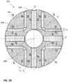
- FIGs. 2A & 2B a cross sectional view of a four pole interior permanent magnet (IPM) rotor 200 is shown in accordance with one or more embodiments.
- This IPM rotor 200 is part of an IPM motor 100 which can include stators 201 connected to the outer surface of the IPM rotor 200.
- the IPM rotor 200 includes a rotor body 202.
- the rotor body 202 is a ferromagnetic core with a central axial bore 208 and is comprised of a plurality of rotor segments.
- the IPM rotor further includes at least one spoke-type IPM 204 that is placed within the rotor body and extends radially outward from the central axial bore to an outer surface of the rotor body 202.
- the rotor body 202 also includes at least one curved IPM 206.
- the curved IPM is located within the rotor body and extends radially outward at an incline with respect to radial plane extending through a center of the spoke-type IPM.
- the magnetic poles of each of the IPM magnets are designated with “N” and “S” to show the north and south poles of each magnet in the arrangement.
- the IPM rotor includes bridge distance h 1 extending from an interior surface of the rotor body 202 from the central axial bore 208 to a surface of the spoke-type IPM 204 that is nearest the central axial bore 208.
- This distance h 1 is selected to obtain full magnetic saturation of the bridge area.
- the distance h 1 is selected that maintains mechanical structural integrity of the rotor body. According to one embodiment the distance h1 is less than 1 millimeter but is not limited thereto.
- the selection of thickness of bridge h 1 between vertical PMs and shaft does not exceed h 1 ⁇ 1.0 mm, in order to obtain high saturation of the ferromagnetic bridge. Otherwise, the leakage flux between neighboring vertical PMs is high.
- the thickness of the bridge h 2 between V-shaped PMs and shaft can be greater, but usually, dependent on the size of the rotor and dimensions of PMs. For example, in one embodiment the bridge is less than h 2 ⁇ 10 mm. In one embodiment, if the bridge h 1 must be very thin from electromagnetic point of view, the rotor can be protected against mechanical stresses with the aid of two non-ferromagnetic disks at each end of the stack and axial bolts.
- a second bridge distance h 2 can also be provided that extends from the inner surface of the rotor body 202 from the central axial bore 208 to a surface of the curved IPM 206 that is nearest the central axial bore 208 as shown.
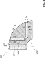
- FIG. 3 is a cross sectional view of one segment 301 of an interior permanent magnet (IPM) rotor in accordance with one or more embodiments of the present disclosure.
- the segment 301 includes a portion of the rotor body 302 that includes one set of magnets.
- the segment 301 of the rotor body 302 includes a spoke-type IPM 304 and a curved IPM 306.
- the central axial bore 308 makes up the inner most portion of the segment 301.
- this particular segment 301 would make up one fourth an entire IPM rotor in the case of a four pole machine.
- the segment can be compressed such that 6 or as many as 10 or more segments are provided that make up the IPM rotor, dependent on the number of poles. A version of such compression in shown in FIG. 4 .
- FIG. 4 is a cross-sectional view of another interior permanent magnet (IPM) rotor 400 in accordance with one or more embodiments of the present disclosure.
- the IPM rotor 400 includes a plurality of spoke-type IPMs 404 and a plurality of V-shaped IPMs 406. These elements are arranged in an alternating pattern around the central axial bore 208 as shown. As shown, this IPM rotor 400 has six segments that correspond to a six pole motor. According to other embodiments, more or less poles can be provided.
- FIG. 5 is a cross sectional view of one segment 501 of an interior permanent magnet (IPM) rotor in accordance with one or more exemplary embodiments of the present disclosure.
- the segment 501 includes a part of the rotor body 502 and a pair of magnets.
- the segment 501 includes a spoke-type magnet 504 and a U-shaped magnet 506 that are arranged extending radially outward from the central axial bore 508.
- FIG. 6 is a cross sectional view of one segment 501 of an interior permanent magnet (IPM) rotor in accordance with one or more embodiments of the present disclosure.
- This segment 501 includes a part of rotor body 502 that includes a number of magnets.
- a spoke-type IPM 504 is provided that extends radially outward from the central axial bore 508.
- a first curved magnet 606.1, a second curved magnet 606.2, and a third magnet 606.3 that are provided in layers extending outward from the central axial bore 508.
- FIG. 7 is a flowchart of a method of providing an interior permanent magnet (IPM) rotor in accordance with one or more embodiments of the present disclosure.
- the method 700 includes providing a rotor body that rotates around a central rotational axis that is a ferromagnetic core with a central axial bore and is comprised of a plurality of rotor segments that each correspond to a pole of the IPM motor (operation 705).
- the method 700 also includes providing, in at least one of the plurality of rotor segments, a spoke-type interior permanent magnet (IPM) within the rotor body and extending radially outward from the central axial bore to an outer surface of the rotor body (operation 710).
- IPM interior permanent magnet
- the method 700 includes providing, in the at least one of the plurality of rotor segments, a curved interior permanent magnet (IPM) within the rotor body and extending radially outward at an incline with respect to a radial plane extending through a center of the spoke-type IPM.
- IPM interior permanent magnet
- embodiments described herein provide a result of synergistic integration. For example the performance, manufacturing process and reliability is improved. The weight and volume of the motor can be also reduced.
- the IPM rotor shows the following advantages: (a) High magnetic flux density in the air gap as a result of integration of spoke-type PMs with V-shaped PMs; (b) High magnetic flux density in the air gap which provides high torque and dynamic performance of IPM synchronous motor; (c) High magnetic flux density in the air gap also allows for reduction of the volume envelope and weight of the machine; (d) Easy manufacture, because the IPM rotor does not need any non-ferromagnetic retaining sleeve; (e) High reliability; and (f) Cost-effective manufacturing because, if necessary, SmCo or NdFeB PMs can be replaced with cheaper ferrite magnets.
- each block in the flowchart or block diagrams may represent a module, segment, or portion of instructions, which comprises one or more executable instructions for implementing the specified logical function(s).
- the functions noted in the blocks may occur out of the order noted in the Figures.
- two blocks shown in succession may, in fact, be executed substantially concurrently, or the blocks may sometimes be executed in the reverse order, depending upon the functionality involved.
Landscapes
- Engineering & Computer Science (AREA)
- Power Engineering (AREA)
- Manufacturing & Machinery (AREA)
- Permanent Field Magnets Of Synchronous Machinery (AREA)
Abstract
Description
- The subject matter disclosed herein generally relates to a permanent magnet rotor and, more particularly, to the interior placement of permanent magnets within a permanent magnet rotor.
- Permanent magnet (PM) synchronous motors are found in a broad assortment of applications ranging from automotive, aircraft, watercraft, robotics, machinery, and other areas as well. As way of example only, in aerospace electromechanical drives have been used in electric fuel pumps, electric actuation systems for flight control, electric cabin air compressors, nitrogen generation systems, compartment refrigeration units, and supplemental cooling units.
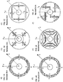
- A number of different arrangements of the magnets have been provided within permanent magnet motors. For example, as shown in
FIG. 1A through FIG. 1F rotor configuration for PM synchronous motors have included: (a) surface-magnet rotor; (b) spoke-type magnet rotor; (c) interior-magnet rotor with flat PMs; (d) inset-magnet rotor; (e) rotor with double-layer interior magnets; and (f) rotor with buried magnets asymmetrically distributed. d-axis (direct axis) is the center axis of magnetic pole, q-axis (quadrature axis) is the axis electromagnetically orthogonal to the d-axis. However, this list is not exhaustive of all possible arrangements. - Accordingly, there is a constant desire for improvements in the magnet arrangement within these PM motors to provide desired motor properties.
- According to one embodiment an interior permanent magnet (IPM) rotor is provided. The IPM rotor includes a rotor body that rotates around a central rotational axis, wherein the rotor body is a ferromagnetic core with a central axial bore and includes a plurality of rotor segments, wherein each rotor segment corresponds to a pole of the IPM motor, and wherein at least one of the rotor segments of the plurality of rotor segments includes a spoke-type interior permanent magnet (IPM) disposed within the rotor body and extending radially outward from the central axial bore to an outer surface of the rotor body, and a curved interior permanent magnet (IPM) disposed within the rotor body and extending radially outward at an incline with respect to a radial plane extending through a center of the spoke-type IPM.
- In addition to one or more of the features described above, or as an alternative, further embodiments may include a bridge distance extending from an interior surface of the rotor body from the central axial bore to a surface of the spoke-type IPM that is nearest the central axial bore.
- In addition to one or more of the features described above, or as an alternative, further embodiments may include, wherein the bridge distance is selected to obtain full magnetic saturation of the bridge area.
- In addition to one or more of the features described above, or as an alternative, further embodiments may include wherein the bridge distance is selected that maintains mechanical structural integrity of the rotor body.
- In addition to one or more of the features described above, or as an alternative, further embodiments may include wherein the bridge distance is less than 1 millimeter.
- In addition to one or more of the features described above, or as an alternative, further embodiments may include wherein the IPM rotor is a 4-pole IPM rotor.
- In addition to one or more of the features described above, or as an alternative, further embodiments may include wherein the IPM rotor is at least one selected from a group consisting of a 2-pole IPM rotor, a 6-pole IPM rotor, 8-pole IPM rotor, a 10-pole IPM rotor, an 12-pole IPM rotor, an 14-pole IPM rotor, and a 16-pole IPM rotor.
- In addition to one or more of the features described above, or as an alternative, further embodiments may include wherein the plurality of segments are arranged such that an alternating pattern is provided between the spoke-type magnets and curved IPMs.
- In addition to one or more of the features described above, or as an alternative, further embodiments may include wherein the curved IPM is V-shaped.
- In addition to one or more of the features described above, or as an alternative, further embodiments may include wherein the curved IPM is one selected from a group consisting of a C-shaped IPM, a U-shaped IPM, and a half-ring shaped IPM.
- In addition to one or more of the features described above, or as an alternative, further embodiments may include multiple curved-shaped IPMs disposed in layers extending radially outward within the rotor body.
- In addition to one or more of the features described above, or as an alternative, further embodiments may include a stator attached to an outer surface of the rotor.
- In addition to one or more of the features described above, or as an alternative, further embodiments may include wherein the spoke-type IPM and the curved IPM are selected from one or more of a SmCo permanent magnet and an NdFeB permanent magnet.
- In addition to one or more of the features described above, or as an alternative, further embodiments may include wherein the spoke-type IPM and the curved IPM are ferrite magnets.
- According to an embodiment a permanent magnet synchronous motor system is provided. The system includes an interior permanent magnet (IPM) rotor including a rotor body that rotates around a central rotational axis, wherein the rotor is a ferromagnetic core with a central axial bore and is included of a plurality of rotor segments, wherein each segment corresponds to a pole of the IPM motor, wherein at least one of the rotor segments of the plurality of rotor segments includes a spoke-type interior permanent magnet (IPM) disposed within the rotor body and extending radially outward from the central axial bore to an outer surface of the rotor body, and a curved interior permanent magnet (IPM) disposed within the rotor body and extending radially outward at an incline with respect to a radial plane extending through a center of the spoke-type IPM, and a stator attached to an outer surface of the interior permanent magnet (IPM) rotor.
- In addition to one or more of the features described above, or as an alternative, further embodiments may include wherein the PM synchronous motor system is a PM synchronous brushless motor system.
- In addition to one or more of the features described above, or as an alternative, further embodiments may include a bridge distance extending from an interior surface of the rotor body from the central axial bore to a surface of the spoke-type IPM that is nearest the central axial bore.
- In addition to one or more of the features described above, or as an alternative, further embodiments may include wherein the plurality of segments are arranged such that an alternating pattern is provided between the spoke-type magnets and curved IPMs.
- In addition to one or more of the features described above, or as an alternative, further embodiments may include multiple curved-shaped IPMs disposed in layers extending radially outward within the rotor body.
- In addition to one or more of the features described above, or as an alternative, further embodiments may include wherein the bridge distance is selected to obtain full magnetic saturation of the bridge area, and wherein the bridge distance is selected that maintains mechanical structural integrity of the rotor body.
- According to an embodiment a method of providing an interior permanent magnet (IPM) rotor is provided. The method includes providing a rotor body that rotates around a central rotational axis that is a ferromagnetic core with a central axial bore and is included of a plurality of rotor segments that each correspond to a pole of the IPM motor, providing, in at least one of the plurality of rotor segments, a spoke-type interior permanent magnet (IPM) within the rotor body and extending radially outward from the central axial bore to an outer surface of the rotor body, and providing, in the at least one of the plurality of rotor segments, a curved interior permanent magnet (IPM) within the rotor body and extending radially outward at an incline with respect to a radial plane extending through a center of the spoke-type IPM.
- The foregoing features and elements may be combined in various combinations without exclusivity, unless expressly indicated otherwise. These features and elements as well as the operation thereof will become more apparent in light of the following description and the accompanying drawings. It should be understood, however, that the following description and drawings are intended to be illustrative and explanatory in nature and non-limiting.
- The foregoing and other features, and advantages of the present disclosure are apparent from the following detailed description taken in conjunction with the accompanying drawings in which:
-
FIGs. 1A, 1B, 1C, 1D , IE, and 1F are cross sectional views of permanent magnet motor arrangements; -
FIG. 2A is a cross sectional view of a four pole interior permanent magnet (IPM) motor in accordance with one or more embodiments of the present disclosure; -
FIG. 2B is a cross sectional view of a four pole interior permanent magnet (IPM) rotor in accordance with one or more embodiments of the present disclosure; -
FIG. 3 is a cross sectional view of one segment of an interior permanent magnet (IPM) rotor in accordance with one or more embodiments of the present disclosure; -
FIG. 4 is a cross sectional view of another interior permanent magnet (IPM) rotor in accordance with one or more embodiments of the present disclosure; -
FIG. 5 is a cross sectional view of one segment of an interior permanent magnet (IPM) rotor in accordance with one or more embodiments of the present disclosure; -
FIG. 6 is a cross sectional view of one segment of an interior permanent magnet (IPM) rotor in accordance with one or more embodiments of the present disclosure; and -
FIG. 7 is a flowchart of a method of providing an interior permanent magnet (IPM) rotor in accordance with one or more embodiments of the present disclosure. - As shown and described herein, various features of the disclosure will be presented. Various embodiments may have the same or similar features and thus the same or similar features may be labeled with the same reference numeral, but preceded by a different first number indicating the figure to which the feature is shown. Thus, for example, element "a" that is shown in FIG. X may be labeled "Xa" and a similar feature in FIG. Z may be labeled "Za." Although similar reference numbers may be used in a generic sense, various embodiments will be described and various features may include changes, alterations, modifications, etc. as will be appreciated by those of skill in the art, whether explicitly described or otherwise would be appreciated by those of skill in the art.
- Embodiments described herein are directed to an interior permanent magnet (IPM) rotor that includes a rotor body that rotates around a central rotational axis. The rotor body is a ferromagnetic core with a central axial bore and is comprised of a plurality of rotor segments.
- Further, each segment corresponds to a pole of the IPM motor. At least one of the rotor segments of the plurality of rotor segments includes a spoke-type interior permanent magnet (IPM) disposed within the rotor body and extending radially outward from the central axial bore to an outer surface of the rotor body. Also, the at least one rotor segment also includes a curved interior permanent magnet (IPM) disposed within the rotor body and extending radially outward at an incline with respect to a radial plane extending through a center of the spoke-type IPM.
- According to one or more embodiments, a PM synchronous brushless motor (PM motor) includes a four pole IPM rotor as shown in
FIGs. 2A &2B . This motor has a higher magnetic flux density in the air gap than other PM rotors shown inFIG. 1 . By providing a higher magnetic flux density in the air gap this IPM motor can provide a higher torque and better dynamic performance. Further, the IPM rotor is easy to manufacture, because it does not need any non-ferromagnetic retaining sleeve. - Additionally, in accordance with one or more embodiments, the PM motor is provided with a high degree of reliable, because the PMs are naturally protected against mechanical centrifugal stresses by being located within the rotor body. Additionally, the reliability of the PM motor is improved compared to other designs because the PMs are electromagnetically protected against demagnetization at reversals or abnormal operation because the armature reaction magnetic flux penetrating from the stator to the rotor goes through laminated ferromagnetic core (low reluctance), thus omitting PMs. Also, the IPM motor allows for application of cost-effective ferrite magnets instead of expensive SmCo or NdFeB PMs. Though either can be used in accordance with embodiments disclosed herein.
- For example, turning now to
FIGs. 2A &2B , a cross sectional view of a four pole interior permanent magnet (IPM)rotor 200 is shown in accordance with one or more embodiments. ThisIPM rotor 200 is part of an IPM motor 100 which can includestators 201 connected to the outer surface of theIPM rotor 200. TheIPM rotor 200 includes arotor body 202. Therotor body 202 is a ferromagnetic core with a centralaxial bore 208 and is comprised of a plurality of rotor segments. The IPM rotor further includes at least one spoke-type IPM 204 that is placed within the rotor body and extends radially outward from the central axial bore to an outer surface of therotor body 202. Therotor body 202 also includes at least onecurved IPM 206. The curved IPM is located within the rotor body and extends radially outward at an incline with respect to radial plane extending through a center of the spoke-type IPM. - The magnetic poles of each of the IPM magnets are designated with "N" and "S" to show the north and south poles of each magnet in the arrangement.
- Further, the IPM rotor includes bridge distance h1 extending from an interior surface of the
rotor body 202 from the centralaxial bore 208 to a surface of the spoke-type IPM 204 that is nearest the centralaxial bore 208. This distance h1 is selected to obtain full magnetic saturation of the bridge area. Further, according to another embodiment, the distance h1 is selected that maintains mechanical structural integrity of the rotor body. According to one embodiment the distance h1 is less than 1 millimeter but is not limited thereto. - According to one embodiment, for example, the selection of thickness of bridge h1 between vertical PMs and shaft does not exceed h1≤ 1.0 mm, in order to obtain high saturation of the ferromagnetic bridge. Otherwise, the leakage flux between neighboring vertical PMs is high. The thickness of the bridge h2 between V-shaped PMs and shaft can be greater, but usually, dependent on the size of the rotor and dimensions of PMs. For example, in one embodiment the bridge is less than h2 ≤ 10 mm. In one embodiment, if the bridge h1 must be very thin from electromagnetic point of view, the rotor can be protected against mechanical stresses with the aid of two non-ferromagnetic disks at each end of the stack and axial bolts.
- Further, according to another embodiment, a second bridge distance h2 can also be provided that extends from the inner surface of the
rotor body 202 from the centralaxial bore 208 to a surface of thecurved IPM 206 that is nearest the centralaxial bore 208 as shown. -
FIG. 3 is a cross sectional view of onesegment 301 of an interior permanent magnet (IPM) rotor in accordance with one or more embodiments of the present disclosure. Thesegment 301 includes a portion of therotor body 302 that includes one set of magnets. Specifically, thesegment 301 of therotor body 302 includes a spoke-type IPM 304 and acurved IPM 306. As shown the centralaxial bore 308 makes up the inner most portion of thesegment 301. As shown, thisparticular segment 301 would make up one fourth an entire IPM rotor in the case of a four pole machine. However, according to other embodiments, the segment can be compressed such that 6 or as many as 10 or more segments are provided that make up the IPM rotor, dependent on the number of poles. A version of such compression in shown inFIG. 4 . - For example,
FIG. 4 is a cross-sectional view of another interior permanent magnet (IPM)rotor 400 in accordance with one or more embodiments of the present disclosure. TheIPM rotor 400 includes a plurality of spoke-type IPMs 404 and a plurality of V-shapedIPMs 406. These elements are arranged in an alternating pattern around the centralaxial bore 208 as shown. As shown, thisIPM rotor 400 has six segments that correspond to a six pole motor. According to other embodiments, more or less poles can be provided. - According to another embodiment,
FIG. 5 is a cross sectional view of onesegment 501 of an interior permanent magnet (IPM) rotor in accordance with one or more exemplary embodiments of the present disclosure. Thesegment 501 includes a part of therotor body 502 and a pair of magnets. Specifically thesegment 501 includes a spoke-type magnet 504 and aU-shaped magnet 506 that are arranged extending radially outward from the centralaxial bore 508. - According to other embodiments,
FIG. 6 is a cross sectional view of onesegment 501 of an interior permanent magnet (IPM) rotor in accordance with one or more embodiments of the present disclosure. Thissegment 501 includes a part ofrotor body 502 that includes a number of magnets. Specifically, a spoke-type IPM 504 is provided that extends radially outward from the centralaxial bore 508. Also provided are a first curved magnet 606.1, a second curved magnet 606.2, and a third magnet 606.3 that are provided in layers extending outward from the centralaxial bore 508. -
FIG. 7 is a flowchart of a method of providing an interior permanent magnet (IPM) rotor in accordance with one or more embodiments of the present disclosure. Themethod 700 includes providing a rotor body that rotates around a central rotational axis that is a ferromagnetic core with a central axial bore and is comprised of a plurality of rotor segments that each correspond to a pole of the IPM motor (operation 705). Themethod 700 also includes providing, in at least one of the plurality of rotor segments, a spoke-type interior permanent magnet (IPM) within the rotor body and extending radially outward from the central axial bore to an outer surface of the rotor body (operation 710). Further, themethod 700 includes providing, in the at least one of the plurality of rotor segments, a curved interior permanent magnet (IPM) within the rotor body and extending radially outward at an incline with respect to a radial plane extending through a center of the spoke-type IPM. - Advantageously, embodiments described herein provide a result of synergistic integration. For example the performance, manufacturing process and reliability is improved. The weight and volume of the motor can be also reduced.
- Additionally, the IPM rotor shows the following advantages: (a) High magnetic flux density in the air gap as a result of integration of spoke-type PMs with V-shaped PMs; (b) High magnetic flux density in the air gap which provides high torque and dynamic performance of IPM synchronous motor; (c) High magnetic flux density in the air gap also allows for reduction of the volume envelope and weight of the machine; (d) Easy manufacture, because the IPM rotor does not need any non-ferromagnetic retaining sleeve; (e) High reliability; and (f) Cost-effective manufacturing because, if necessary, SmCo or NdFeB PMs can be replaced with cheaper ferrite magnets.
- While the present disclosure has been described in detail in connection with only a limited number of embodiments, it should be readily understood that the present disclosure is not limited to such disclosed embodiments. Rather, the present disclosure can be modified to incorporate any number of variations, alterations, substitutions, combinations, sub-combinations, or equivalent arrangements not heretofore described, but which are within the scope of the present invention as defined by the claims. Additionally, while various embodiments of the present disclosure have been described, it is to be understood that aspects of the present disclosure may include only some of the described embodiments.
- The terminology used herein is for the purpose of describing particular embodiments only and is not intended to be limiting. As used herein, the singular forms "a", "an" and "the" are intended to include the plural forms as well, unless the context clearly indicates otherwise. It will be further understood that the terms "comprises" and/or "comprising," when used in this specification, specify the presence of stated features, integers, steps, operations, elements, and/or components, but do not preclude the presence or addition of one or more other features, integers, steps, operations, elements, components, and/or groups thereof.
- The corresponding structures, materials, acts, and equivalents of all means or step plus function elements in the claims below are intended to include any structure, material, or act for performing the function in combination with other claimed elements as specifically claimed. The description has been presented for purposes of illustration and description, but is not intended to be exhaustive or limited to the embodiments in the form disclosed. Many modifications and variations will be apparent to those of ordinary skill in the art without departing from the scope of the invention as defined by the claims. The embodiments were chosen and described in order to best explain the principles of the disclosure and the practical application, and to enable others of ordinary skill in the art to understand various embodiments with various modifications as are suited to the particular use contemplated.
- Aspects of the present invention are described herein with reference to flowchart illustrations and/or block diagrams of methods, apparatus (systems), and computer program products according to embodiments. It will be understood that each block of the flowchart illustrations and/or block diagrams, and combinations of blocks in the flowchart illustrations and/or block diagrams, can be implemented by computer readable program instructions.
- The flowchart and block diagrams in the Figures illustrate the architecture, functionality, and operation of possible implementations of systems, methods, and computer program products according to various embodiments. In this regard, each block in the flowchart or block diagrams may represent a module, segment, or portion of instructions, which comprises one or more executable instructions for implementing the specified logical function(s). In some alternative implementations, the functions noted in the blocks may occur out of the order noted in the Figures. For example, two blocks shown in succession may, in fact, be executed substantially concurrently, or the blocks may sometimes be executed in the reverse order, depending upon the functionality involved. It will also be noted that each block of the block diagrams and/or flowchart illustration, and combinations of blocks in the block diagrams and/or flowchart illustration, can be implemented by special purpose hardware-based systems that perform the specified functions or acts or carry out combinations of special purpose hardware and computer instructions.
- The descriptions of the various embodiments have been presented for purposes of illustration, but are not intended to be exhaustive or limited to the embodiments disclosed. Many modifications and variations will be apparent to those of ordinary skill in the art without departing from the scope of the claims. The terminology used herein was chosen to best explain the principles of the embodiments, the practical application or technical improvement over technologies found in the marketplace, or to enable others of ordinary skill in the art to understand the embodiments disclosed herein.
- Accordingly, the present disclosure is not to be seen as limited by the foregoing description, but is only limited by the scope of the appended claims.
Claims (15)
- An interior permanent magnet, IPM, rotor comprising:a rotor body (202) that rotates around a central rotational axis,wherein the rotor body is a ferromagnetic core with a central axial bore (208) and is comprised of a plurality of rotor segments,wherein each rotor segment corresponds to a pole of the IPM motor, andwherein at least one of the rotor segments of the plurality of rotor segments comprises:a spoke-type interior permanent magnet, IPM, (204) disposed within the rotor body and extending radially outward from the central axial bore to an outer surface of the rotor body; anda curved interior permanent magnet, IPM, (206) disposed within the rotor body and extending radially outward at an incline with respect to a radial plane extending through a center of the spoke-type IPM,wherein the ferromagnetic core has a bridge distance extending from an interior surface of the rotor body from the central axial bore to a surface of the spoke-type IPM that is nearest the central axial bore, the bridge distance configured to control leakage flux between the spoke-type, IPM and the central axis bore.
- The IPM rotor of claim 1,
wherein the bridge distance is selected to obtain full magnetic saturation of the bridge area. - The IPM rotor of claim 1,
wherein a bridge distance is selected that maintains mechanical structural integrity of the rotor body. - The IPM rotor of claim 1,
wherein the bridge distance is less than 1 millimeter. - The IPM rotor of any preceding claim,
wherein the IPM rotor is at least one selected from a group consisting· of a 2- pole IPM rotor, a 4-pole IPM rotor, a 6-pole IPM rotor, 8-pole IPM rotor, a 10-pole IPM rotor, an 12-pole IPM rotor, an 14-pole IPM rotor, and a 16-pole IPM rotor. - The IPM rotor of any preceding claim,
wherein the curved IPM is V-shaped. - The IPM rotor of any of claims 1 to 5,
wherein the curved IPM is one selected from a group consisting of a C-shaped IPM, a U-shaped IPM, and a half-ring shaped IPM. - The IPM rotor of any preceding claim, further comprising:a stator (201) attached to an outer surface of the rotor.
- The IPM rotor of any preceding claim,
wherein the spoke-type IPM and the curved IPM are selected from one or more of a SmCo permanent magnet and anNdFeB permanent magnet. - The IPM rotor of any of claims 1 to 8,
wherein the spoke-type IPM and the curved IPM are ferrite magnets. - A permanent magnet synchronous motor system comprising:an interior permanent magnet, IPM, rotor (200) comprising:a rotor body (202) that rotates around a central rotational axis (208), wherein the rotor is a ferromagnetic core with a central axial bore and is comprised of a plurality of rotor segments, wherein each segment corresponds to a pole of the IPM motor,wherein at least one of the rotor segments of the plurality of rotor segments comprises:a spoke-type interior permanent magnet, IPM, (204) disposed within the rotor body and extending radially outward from the central axial bore to an outer surface of the rotor body; anda curved interior permanent magnet, IPM, (206) disposed within the rotor body and extending radially outward at an incline with respect to a radial plane extending through a center of the spoke-type IPM; anda stator (201) attached to an outer surface of the interior permanent magnet (IPM) rotor,wherein a bridge distance exists extending from an interior surface of the rotor body from the central axial bore to a surface of the spoke-type IPM that is nearest the central axial bore, the bridge distance configured to control leakage flux between the spoke-type IPM and the central axis bore;.
- The permanent magnet synchronous motor system of claim 11,
wherein the PM synchronous motor system is a PM synchronous brushless motor system. - The permanent magnet synchronous motor system of claims 12 or 12,
wherein the plurality of segments are arranged such that an alternating pattern is provided between the spoke-type magnets and curved IPMs. - The permanent magnet synchronous motor system of any of claims 11 to 13, further comprising:multiple curved-shaped IPMs disposed in layers extending radially outward within the rotor body.
- The permanent magnet synchronous motor system of claim 14,
wherein the bridge distance is selected to obtain full magnetic saturation of the bridge area, and
wherein the bridge distance is selected that maintains mechanical structural integrity of the rotor body.
Applications Claiming Priority (1)
| Application Number | Priority Date | Filing Date | Title |
|---|---|---|---|
| US15/251,149 US10516307B2 (en) | 2016-08-30 | 2016-08-30 | Interior permanent magnet motor/rotor with curved and spoke-type permanent magnets |
Publications (2)
| Publication Number | Publication Date |
|---|---|
| EP3291415A2 true EP3291415A2 (en) | 2018-03-07 |
| EP3291415A3 EP3291415A3 (en) | 2018-03-21 |
Family
ID=59738252
Family Applications (1)
| Application Number | Title | Priority Date | Filing Date |
|---|---|---|---|
| EP17188274.9A Withdrawn EP3291415A3 (en) | 2016-08-30 | 2017-08-29 | Interior permanent magnet rotor |
Country Status (2)
| Country | Link |
|---|---|
| US (1) | US10516307B2 (en) |
| EP (1) | EP3291415A3 (en) |
Families Citing this family (12)
| Publication number | Priority date | Publication date | Assignee | Title |
|---|---|---|---|---|
| FR3064837B1 (en) * | 2017-04-03 | 2020-01-17 | Moving Magnet Technologies | ROTOR FOR ELECTRIC MACHINE WITH INTERNAL PERMANENT MAGNETS |
| US11063485B2 (en) * | 2018-05-11 | 2021-07-13 | Steering Solutions Ip Holding Corporation | Interior permanent magnet machine with hybrid rotor topology |
| CN113875136A (en) * | 2019-06-04 | 2021-12-31 | 三菱电机株式会社 | Ring for magnetization, magnetization method, magnetization device, rotor, electric motor, compressor and air conditioner |
| WO2021134276A1 (en) | 2019-12-30 | 2021-07-08 | 安徽威灵汽车部件有限公司 | Rotor of electric motor, driving electric motor, and vehicle |
| CN113131643B (en) * | 2019-12-30 | 2022-12-02 | 安徽威灵汽车部件有限公司 | Rotor of motor, driving motor and vehicle |
| CN111049345B (en) * | 2020-01-06 | 2022-03-11 | 浙江大学 | Axial Flux Vernier Motor |
| TWI744860B (en) * | 2020-04-13 | 2021-11-01 | 國立成功大學 | Motor and its spoke type rotor structure having oblique matching dual magnetic parts |
| JP7478104B2 (en) * | 2021-01-08 | 2024-05-02 | 株式会社アイシン | Rotor core |
| JP7090773B1 (en) * | 2021-04-01 | 2022-06-24 | 三菱電機株式会社 | Rotating electric machine |
| JP7679475B2 (en) * | 2021-07-30 | 2025-05-19 | 川崎重工業株式会社 | Rotor and motor |
| CN114123584A (en) * | 2021-11-22 | 2022-03-01 | 华中科技大学 | Built-in vernier permanent magnet motor |
| CN115795704A (en) * | 2022-10-10 | 2023-03-14 | 东风汽车集团股份有限公司 | Design method and system of V-shaped built-in high-speed permanent magnet rotor with multiple magnetic bridges |
Family Cites Families (31)
| Publication number | Priority date | Publication date | Assignee | Title |
|---|---|---|---|---|
| US4405873A (en) * | 1981-10-26 | 1983-09-20 | General Electric Company | Rotor for a line-start permanent-magnet motor |
| TW364234B (en) * | 1997-04-14 | 1999-07-11 | Sanyo Electric Co | Rotor for an electric motor |
| JP3818340B2 (en) * | 1997-09-26 | 2006-09-06 | 株式会社富士通ゼネラル | Permanent magnet motor |
| JPH11103546A (en) * | 1997-09-29 | 1999-04-13 | Fujitsu General Ltd | Permanent magnet motor |
| JP3906882B2 (en) * | 1997-10-24 | 2007-04-18 | 株式会社富士通ゼネラル | Permanent magnet motor |
| DE19933009A1 (en) | 1998-07-24 | 2000-02-10 | Matsushita Electric Industrial Co Ltd | Electric motor e.g. for automobile air conditioning unit, has rotor core provided with slits for reception of internal permanent magnets with non-magnetic section between each permanent magnet and rotor periphery |
| FR2784816B1 (en) * | 1998-10-20 | 2001-01-05 | Valeo Equip Electr Moteur | ROTATING ELECTRIC MACHINE HAVING A NEW ARRANGEMENT OF ROTOR EXCITATION BY PERMANENT MAGNETS |
| FR2787646B1 (en) * | 1998-12-18 | 2001-03-09 | Valeo Equip Electr Moteur | ROTATING ELECTRIC MACHINE WITH PERMANENT MAGNETS AND RELUCTANCE HAVING AN IMPROVED CONSTRUCTION |
| EP1471621A3 (en) * | 2003-04-24 | 2005-12-14 | Minebea Co., Ltd. | Rotor element for an electrical motor |
| US6847144B1 (en) | 2003-12-10 | 2005-01-25 | Industrial Technology Research Institute | Permanent magnet rotor assembly for interior permanent magnet electric motor |
| JP2008253124A (en) * | 2007-03-05 | 2008-10-16 | Nsk Ltd | Rolling bearing device having a radial planar arrangement structure of a rotation sensor |
| JP5134846B2 (en) * | 2007-03-26 | 2013-01-30 | 株式会社東芝 | Permanent magnet motor drive system |
| US7923881B2 (en) | 2007-05-04 | 2011-04-12 | A.O. Smith Corporation | Interior permanent magnet motor and rotor |
| WO2010014844A2 (en) | 2008-07-30 | 2010-02-04 | A.O. Smith Corporation | Interior permanent magnet motor including rotor with unequal poles |
| CN201294443Y (en) * | 2008-12-01 | 2009-08-19 | 东元总合科技(杭州)有限公司 | Permanent magnet self-startup synchronous motor rotor |
| US8004140B2 (en) * | 2009-04-30 | 2011-08-23 | General Electric Company | Dovetail spoke internal permanent magnet machine |
| KR101021120B1 (en) | 2009-07-14 | 2011-03-14 | 한양대학교 산학협력단 | Rotor for high speed motor |
| KR101220381B1 (en) | 2010-12-01 | 2013-01-09 | 현대자동차주식회사 | Interior permanent magnet motor and manufacturing method for the same |
| JP5480176B2 (en) * | 2011-02-03 | 2014-04-23 | アイシン・エィ・ダブリュ株式会社 | Rotating machine rotor |
| KR101566047B1 (en) | 2011-03-29 | 2015-11-05 | 한양대학교 산학협력단 | Spoke type permanent magnet motor |
| EP2568578A3 (en) * | 2011-09-07 | 2017-12-06 | Samsung Electronics Co., Ltd. | Motor and washing machine having the same |
| JP5488625B2 (en) * | 2012-02-13 | 2014-05-14 | 株式会社デンソー | Double stator synchronous motor |
| FR2987184B1 (en) | 2012-02-20 | 2016-07-29 | Moteurs Leroy-Somer | ROTOR OF ROTATING ELECTRIC MACHINE WITH FLOW CONCENTRATION. |
| JP5948127B2 (en) | 2012-04-23 | 2016-07-06 | 日立オートモティブシステムズ株式会社 | Permanent magnet rotating electric machine and electric vehicle using the same |
| KR101418154B1 (en) | 2012-07-17 | 2014-07-09 | 주식회사 팬택 | Terminal having speaker unit |
| KR102073005B1 (en) * | 2013-07-17 | 2020-02-04 | 삼성전자주식회사 | Motor |
| US20150288233A1 (en) | 2014-04-02 | 2015-10-08 | Samsung Electronics Co., Ltd. | Rotor and motor using the same |
| EP2961044B1 (en) * | 2014-06-27 | 2017-09-13 | Samsung Electronics Co., Ltd. | Motor and its permanent magnet rotor |
| US20160141928A1 (en) | 2014-11-13 | 2016-05-19 | Hiwin Mikrosystem Corp. | Rotor structure of interior-permanent-magnet motor |
| KR20160112412A (en) * | 2015-03-19 | 2016-09-28 | 주식회사 고아정공 | Rotor comprising a rotor core and manufacturing method thereof |
| CN205105071U (en) | 2015-11-11 | 2016-03-23 | 南京康尼电子科技有限公司 | A rotor structure for tangential formula permanent magnet brushless DC motor and motor thereof |
-
2016
- 2016-08-30 US US15/251,149 patent/US10516307B2/en active Active
-
2017
- 2017-08-29 EP EP17188274.9A patent/EP3291415A3/en not_active Withdrawn
Non-Patent Citations (1)
| Title |
|---|
| None |
Also Published As
| Publication number | Publication date |
|---|---|
| US20180062461A1 (en) | 2018-03-01 |
| EP3291415A3 (en) | 2018-03-21 |
| US10516307B2 (en) | 2019-12-24 |
Similar Documents
| Publication | Publication Date | Title |
|---|---|---|
| US10516307B2 (en) | Interior permanent magnet motor/rotor with curved and spoke-type permanent magnets | |
| US11277045B2 (en) | Radially embedded permanent magnet rotor and methods thereof | |
| JP6422595B2 (en) | Electric motor and air conditioner | |
| US9099905B2 (en) | Radially embedded permanent magnet rotor and methods thereof | |
| US9362792B2 (en) | Radially embedded permanent magnet rotor having magnet retention features and methods thereof | |
| US9882440B2 (en) | Radially embedded permanent magnet rotor and methods thereof | |
| US10033234B2 (en) | Motor | |
| US9831727B2 (en) | Permanent magnet rotor and methods thereof | |
| US9577483B2 (en) | Rotor for a permanent-magnet embedded motor having permanent magnets fitted into a plurality of magnet insertion holes formed in a circumferential direction | |
| US9899897B2 (en) | Permanent magnet buried type electric motor and compressor | |
| US20140103772A1 (en) | Radially embedded permanent magnet rotor and methods thereof | |
| EP2553792A1 (en) | Rotor of an electric machine with embedded permanent magnets and electric machine | |
| CN107078618B (en) | Reluctance assisted external rotor PMSM | |
| JP2000333389A (en) | Permanent magnet motor | |
| US20170179779A1 (en) | Rotor laminations having reduced stress magnet stop | |
| US20220368183A1 (en) | Rotor for a synchronous machine | |
| US20220200375A1 (en) | Four-pole synchronous reluctance motor | |
| EP4047788A1 (en) | Rotary electric machine | |
| EP3271995B1 (en) | External rotor electric machine with smc blocks interposed between permanent magnets | |
| JPH11285186A (en) | Permanent magnet motor | |
| CN115208095A (en) | Motor | |
| US20200220400A1 (en) | Interior permanent magnet electric machine with tapered bridge structure | |
| KR20170075595A (en) | A rotor for interior permanent magnet motors | |
| HK1249969A1 (en) | External rotor electric machine with smc blocks interposed between permanent magnets | |
| HK1243239A1 (en) | Reluctance assisted external rotor pmsm |
Legal Events
| Date | Code | Title | Description |
|---|---|---|---|
| PUAI | Public reference made under article 153(3) epc to a published international application that has entered the european phase |
Free format text: ORIGINAL CODE: 0009012 |
|
| STAA | Information on the status of an ep patent application or granted ep patent |
Free format text: STATUS: THE APPLICATION HAS BEEN PUBLISHED |
|
| PUAL | Search report despatched |
Free format text: ORIGINAL CODE: 0009013 |
|
| AK | Designated contracting states |
Kind code of ref document: A2 Designated state(s): AL AT BE BG CH CY CZ DE DK EE ES FI FR GB GR HR HU IE IS IT LI LT LU LV MC MK MT NL NO PL PT RO RS SE SI SK SM TR |
|
| AX | Request for extension of the european patent |
Extension state: BA ME |
|
| AK | Designated contracting states |
Kind code of ref document: A3 Designated state(s): AL AT BE BG CH CY CZ DE DK EE ES FI FR GB GR HR HU IE IS IT LI LT LU LV MC MK MT NL NO PL PT RO RS SE SI SK SM TR |
|
| AX | Request for extension of the european patent |
Extension state: BA ME |
|
| RIC1 | Information provided on ipc code assigned before grant |
Ipc: H02K 1/27 20060101AFI20180210BHEP |
|
| STAA | Information on the status of an ep patent application or granted ep patent |
Free format text: STATUS: REQUEST FOR EXAMINATION WAS MADE |
|
| 17P | Request for examination filed |
Effective date: 20180921 |
|
| RBV | Designated contracting states (corrected) |
Designated state(s): AL AT BE BG CH CY CZ DE DK EE ES FI FR GB GR HR HU IE IS IT LI LT LU LV MC MK MT NL NO PL PT RO RS SE SI SK SM TR |
|
| STAA | Information on the status of an ep patent application or granted ep patent |
Free format text: STATUS: EXAMINATION IS IN PROGRESS |
|
| 17Q | First examination report despatched |
Effective date: 20201202 |
|
| STAA | Information on the status of an ep patent application or granted ep patent |
Free format text: STATUS: THE APPLICATION IS DEEMED TO BE WITHDRAWN |
|
| 18D | Application deemed to be withdrawn |
Effective date: 20221115 |