EP3291399A1 - Protection apparatus - Google Patents
Protection apparatus Download PDFInfo
- Publication number
- EP3291399A1 EP3291399A1 EP16186690.0A EP16186690A EP3291399A1 EP 3291399 A1 EP3291399 A1 EP 3291399A1 EP 16186690 A EP16186690 A EP 16186690A EP 3291399 A1 EP3291399 A1 EP 3291399A1
- Authority
- EP
- European Patent Office
- Prior art keywords
- electrical network
- impedance
- protection
- admittance
- electrical
- Prior art date
- Legal status (The legal status is an assumption and is not a legal conclusion. Google has not performed a legal analysis and makes no representation as to the accuracy of the status listed.)
- Granted
Links
Images


Classifications
-
- H—ELECTRICITY
- H02—GENERATION; CONVERSION OR DISTRIBUTION OF ELECTRIC POWER
- H02H—EMERGENCY PROTECTIVE CIRCUIT ARRANGEMENTS
- H02H7/00—Emergency protective circuit arrangements specially adapted for specific types of electric machines or apparatus or for sectionalised protection of cable or line systems, and effecting automatic switching in the event of an undesired change from normal working conditions
- H02H7/26—Sectionalised protection of cable or line systems, e.g. for disconnecting a section on which a short-circuit, earth fault, or arc discharge has occured
- H02H7/261—Sectionalised protection of cable or line systems, e.g. for disconnecting a section on which a short-circuit, earth fault, or arc discharge has occured involving signal transmission between at least two stations
-
- H—ELECTRICITY
- H02—GENERATION; CONVERSION OR DISTRIBUTION OF ELECTRIC POWER
- H02H—EMERGENCY PROTECTIVE CIRCUIT ARRANGEMENTS
- H02H3/00—Emergency protective circuit arrangements for automatic disconnection directly responsive to an undesired change from normal electric working condition with or without subsequent reconnection ; integrated protection
- H02H3/006—Calibration or setting of parameters
-
- H—ELECTRICITY
- H02—GENERATION; CONVERSION OR DISTRIBUTION OF ELECTRIC POWER
- H02H—EMERGENCY PROTECTIVE CIRCUIT ARRANGEMENTS
- H02H3/00—Emergency protective circuit arrangements for automatic disconnection directly responsive to an undesired change from normal electric working condition with or without subsequent reconnection ; integrated protection
- H02H3/08—Emergency protective circuit arrangements for automatic disconnection directly responsive to an undesired change from normal electric working condition with or without subsequent reconnection ; integrated protection responsive to excess current
-
- H—ELECTRICITY
- H02—GENERATION; CONVERSION OR DISTRIBUTION OF ELECTRIC POWER
- H02H—EMERGENCY PROTECTIVE CIRCUIT ARRANGEMENTS
- H02H3/00—Emergency protective circuit arrangements for automatic disconnection directly responsive to an undesired change from normal electric working condition with or without subsequent reconnection ; integrated protection
- H02H3/40—Emergency protective circuit arrangements for automatic disconnection directly responsive to an undesired change from normal electric working condition with or without subsequent reconnection ; integrated protection responsive to ratio of voltage and current
Definitions
- This invention relates to a protection apparatus, and to a method of operating a protection apparatus.
- protection devices such as circuit breakers and relays, which are operated in the event of a fault in order to protect an electrical network from the fault.
- a protection apparatus for protecting an electrical network comprising:
- the topological structure of the electrical network may change as a result of a change in condition of one or more components of the electrical network, such as an in-operation connection or disconnection of a component to or from the electrical network, a temporary or permanent removal of a component from the electrical network, and a temporary or permanent addition of a new component to or from the electrical network.
- the change in topological structure of the electrical network may include at least one of:
- An example of an electrical source is, but is not limited to, a distributed generator.
- An example of an electrical load is, but is not limited to, a bus or a feeder.
- the connection or disconnection of a previously open or closed electrical link may arise as a result of a change in switching state of an associated switching device (such as a relay, circuit breaker, and the like).
- the controller may receive the real-time information on the change in topological structure of the electrical network from, for example, another controller, one or more sensors, and one or more components of the electrical network.
- the real-time information may relate to, for example, at least one electrical property of the electrical network, at least one electrical property of one or more components of the electrical network, and a switching state of at least one switching device.
- the protection criterion of the or each protection device is designed on the basis of the previous topological structure of the electrical network prior to the occurrence of the change in topological structure of the electrical network, the change in the topological structure of the electrical network may lead to mal-operation or loss of the protection of the or each protection device as a result of the or each protection criterion not matching up with the new topological structure of the electrical network. Consequently the ability of the or each protection device to react appropriately to a fault would be adversely affected. For example, under such circumstances, the protection ability of the or each protection device may become active when it is not required to do so, or may remain inactive when it is required to do so.
- the protection apparatus of the invention is designed to enable the dynamic and automatic adaptation of the protection criterion of the or each protection device in accordance with the change in the topological structure of the electrical network, which is particularly crucial when the topological structure of the electrical network changes frequently and/or unexpectedly. This in turn eliminates or minimises the exposure of the electrical network to the risk of mal-operation or loss of protection of the or each protection device.
- the ability to dynamically and automatically adapt the protection criterion of the or each protection device in response to the change in the topological structure of the electrical network obviates the need to bring the or each protection device offline (which leaves the electrical network vulnerable to faults) in order to prevent mal-operation or loss of protection of the or each protection device.
- the use of the real-time impedance or admittance matrix conveys information about the new topological structure of the electrical network that permits determination of the or each new protection criterion in a time-efficient manner.
- the controller may be configured to adapt the or each protection criterion by determining an equivalent source voltage and/or an equivalent impedance or admittance seen by the or each protection device based on the real-time impedance or admittance matrix, and by determining the or each protection criterion based on the determined equivalent source voltage and/or equivalent impedance or admittance.
- the controller may be configured to adapt the or each protection criterion by determining an equivalent source voltage and/or an equivalent impedance or admittance seen by the or each protection device based on the real-time impedance or admittance matrix and on measured voltage and current of a part (e.g. a node) of the electrical network corresponding to the or each protection device, and by determining the or each protection criterion based on the determined equivalent source voltage and/or equivalent impedance or admittance.
- a part e.g. a node
- Information about the new topological structure of the electrical network conveyed in the form of the equivalent source voltage and/or the equivalent impedance or admittance seen by the or each protection device enables ready determination of the or each new protection criterion.
- the equivalent source voltage and the equivalent impedance or admittance are respectively the Thevenin equivalent source voltage and the Thevenin equivalent impedance or admittance.
- the controller may be configured to perform the online determination of the real-time impedance or admittance matrix of the electrical network by modifying a reference impedance or admittance matrix of the electrical network based on the change in topological structure of the electrical network so as to determine the real-time impedance or admittance matrix.
- Modifying the reference impedance or admittance matrix results in a more time-efficient determination of the real-time impedance or admittance matrix, especially when the topological structure of the electrical network changes frequently and/or unexpectedly, when compared to determining the real-time impedance or admittance matrix without using a reference starting point.
- the controller may be configured to receive information on the topological structure of the electrical network and to perform a determination of the reference impedance or admittance matrix prior to the change in topological structure of the electrical network. Configuring the controller in this manner permits automatic determination of the reference impedance or admittance matrix.
- One way of determining the reference impedance or admittance matrix may be or may include the use of the branch addition method.
- the determination of the reference impedance or admittance matrix may be an offline determination of the reference impedance or admittance matrix. Such offline determination by the controller may be carried out, for example, during installation of the electrical network or a new component of the electrical network, or when the electrical network is brought offline.
- the reference impedance or admittance matrix may be determined offline through other means, such as a controller or computer external to the electrical network, before the reference impedance or admittance matrix is provided as an input to the controller.
- the reference impedance or admittance matrix may omit at least one electrical source of the electrical network and/or at least one electrical load of the electrical network. This simplifies the determination of the reference impedance or admittance matrix, since the electrical network may experience frequent and/or unexpected connection and disconnections of at least one electrical source and/or at least one electrical load.
- the controller may be configured to determine an equivalent impedance or admittance value of at least one component of the electrical network and to combine the or each equivalent impedance or admittance value into the reference impedance or admittance matrix by addition or subtraction so as to determine the real-time impedance or admittance matrix.
- the modification of the reference impedance or admittance matrix in this manner provides a real-time impedance or admittance matrix that accurately reflects the current state of the topological structure of the electrical network.
- the or each equivalent impedance or admittance value may be selected from a group including:
- the controller may be configured in a variety of ways, examples of which are described as follows.
- the controller may be a single control unit or may include a plurality of control units.
- the controller may include a first control unit and at least one second control unit, the first control unit in communication with the or each second control unit.
- the or each second control unit may be associated with the or the respective protection device.
- the first control unit may be a higher level controller, such as a substation level controller.
- the first control unit and/or the or each second control unit may also be in communication with one or more other control units, for example, a global controller.
- the first control unit may be configured to: receive real-time information about a part of the electrical network corresponding to the or each protection device from the or each second control unit; and perform the online determination of the real-time impedance or admittance matrix based on the received real-time information from the or each second control unit.
- the real-time information from the or each second control unit may relate to, for example, electrical properties of the or each protection device, such as current and voltage, and a switching state of the or each protection device.
- the first control unit may be configured to transmit the real-time impedance or admittance matrix to the or each second control unit, and the or each second control unit may be configured to adapt the or each protection criterion based on the real-time impedance or admittance matrix.
- Determining the real-time impedance or admittance matrix using the first control unit and adapt the or each protection criterion using the or each second control unit in this manner enables the determination of the real-time impedance or admittance matrix and the adaptation of the or each protection criterion to be performed on different levels. This in turn permits a reduction in the dimension of the real-time impedance or admittance matrix, which improves the reliability efficiency of the controller in carrying out its various tasks.
- Dividing the tasks of determining the real-time impedance or admittance matrix and adapting the or each protection criterion between the first and second control units in the foregoing manner can be particularly effective when there are a high number of protection devices and therefore a high number of second control units, or when the invention is used for an electrical network with a large and/or a complex topology.
- the or each protection device may be or may include an overcurrent relay
- the or each protection criterion may be or may include a fault level of a circuit interruption device (e.g. a circuit breaker) associated with the overcurrent relay and/or a setting value of the overcurrent relay.
- a circuit interruption device e.g. a circuit breaker
- the invention is particularly applicable to an overcurrent relay, since the fault level of a circuit interruption device associated with the overcurrent relay and/or a setting value of the overcurrent relay can be affected by a change in topological structure of the electrical network.
- the or each protection device may be or may include a distance protection relay
- the or each protection criterion may be or may include a reach setting value of the distance protection relay.
- the invention is particularly applicable to a distance protection relay, since the accuracy of the reach setting value of the distance protection relay can be affected by a change in topological structure of the electrical network.
- a protection apparatus for protecting an electrical network
- the protection apparatus comprising at least one protection device configured to protect the electrical network from a fault in response to a or a respective protection criterion being met, the method including the steps of:
- the change in topological structure of the electrical network may include at least one of:
- the method of the invention may include the step of adapting the or each protection criterion by determining an equivalent source voltage and/or an equivalent impedance or admittance seen by the or each protection device based on the real-time impedance or admittance matrix, and by determining the or each protection criterion based on the determined equivalent source voltage and/or equivalent impedance or admittance.
- the method of the invention may further include the step of adapting the or each protection criterion by determining an equivalent source voltage and/or an equivalent impedance or admittance seen by the or each protection device based on the real-time impedance or admittance matrix and on measured voltage and current of a part (e.g. a node) of the electrical network corresponding to the or each protection device, and by determining the or each protection criterion based on the determined equivalent source voltage and/or equivalent impedance or admittance.
- a part e.g. a node
- the equivalent source voltage and the equivalent impedance or admittance may be respectively the Thevenin equivalent source voltage and the Thevenin equivalent impedance or admittance.
- the method of the invention may further include the step of performing the online determination of the real-time impedance or admittance matrix of the electrical network by modifying a reference impedance or admittance matrix of the electrical network based on the change in topological structure of the electrical network so as to determine the real-time impedance or admittance matrix.
- the method of the invention may further include the steps of: receiving information on the topological structure of the electrical network and performing a determination of the reference impedance or admittance matrix prior to the change in topological structure of the electrical network.
- the determination of the reference impedance or admittance matrix may be an offline determination of the reference impedance or admittance matrix.
- the reference impedance or admittance matrix may omit at least one electrical source of the electrical network and/or at least one electrical load of the electrical network.
- the method of the invention may further include the steps of: determining an equivalent impedance or admittance value of at least one component of the electrical network; and combining the or each equivalent impedance or admittance value into the reference impedance or admittance matrix by addition or subtraction so as to determine the real-time impedance or admittance matrix.
- the or each equivalent impedance or admittance value may be selected from a group including:
- the or each protection device may be or may include an overcurrent relay
- the or each protection criterion may be or may include a fault level of a circuit interruption device (e.g. a circuit breaker) associated with the overcurrent relay and/or a setting value of the overcurrent relay.
- a circuit interruption device e.g. a circuit breaker
- the or each protection device may be or may include a distance protection relay, and the or each protection criterion may be or may include a reach setting value of the distance protection relay.
- An electrical network 20 is shown in Figure 1 and is designated generally by the reference numeral 20.
- the electrical network 20 includes a substation with first, second and third buses 22, 24, 26.
- the first bus 22 is connected to a higher level section of the electrical network 20 (such as a power transmission section) which is depicted by an equivalent source voltage and system impedance Z s .
- the first bus 22 is connected to the second bus 24 via a transformer, and the first bus 22 is also connected to the third bus 26 via another transformer.
- Respective breakers are connected on both sides of each transformer.
- the second and third buses 24, 26 are interconnected via an electrical link that includes a breaker.
- a plurality of feeders 30 extends from the second bus 24, and a distributed generator 32 is connected to one of the feeders 30 extending from the second bus 24.
- Another plurality of feeders 30 extends from the third bus 26, and another distributed generator 32 is connected via a breaker to the third bus 26.
- each protection device is in the form of an overcurrent relay, which is configured to operate an associated breaker to switch to an open state to disconnect the corresponding feeder 30 in the event of an overcurrent resulting in its protection criterion being met.
- the configuration of each overcurrent relay in this way enables it to protect the corresponding feeder 30 from the overcurrent.
- Each protection criterion i.e. the fault level of the breaker associated with each overcurrent relay and the setting value of each overcurrent relay, is calculated from the equivalent source voltage E TH and the equivalent impedance Z TH of the electrical network 20 as seen by each overcurrent relay.
- Figure 2 schematically shows the Thevenin equivalent source voltage E TH and the Thevenin equivalent impedance Z TH seen by a protection device of the electrical network 20 of Figure 1 .
- the equivalent source voltage and the equivalent impedance of the electrical network 20 as seen by each overcurrent relay may change due to a change in topological structure of the electrical network 20.
- the change in topological structure of the electrical network 20 may include at least one of: a connection or disconnection of at least one distributed generator 32 into or from the electrical network 20; a connection or disconnection of at least one feeder 30 into or from the electrical network 20; a connection of at least one previously open electrical link of the electrical network 20 due to the closing of an associated breaker; a disconnection of at least one previously closed electrical link of the electrical network 20 due to the opening of an associated breaker; an increase or decrease in power of at least one connected feeder 30 or at least one connected distributed generator 32 of the electrical network 20.
- the change in the equivalent source voltage E TH and the equivalent impedance Z TH of the electrical network 20 as seen by a given overcurrent relay means that the corresponding protection criterion no longer matches the new topological structure of the electrical network 20, which could lead to mal-operation or loss of protection of the or each protection device. This in turn leaves the electrical network 20 vulnerable to overcurrents, and adversely affects the performance of each protection device.
- the protection apparatus further includes a controller.
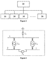
- the controller includes a first control unit, which is in the form of a central control unit 34, and a plurality of second control units, which is in the form of a distributed control unit 36.
- Each distributed control unit 36 is associated with a respective one of the overcurrent relays.
- the central control unit 34 is in communication with each of the distributed control units 36. In this way the central control unit 34 can obtain real-time information from each distributed control unit 36 and transmit information back to each distributed control unit 36, while each distributed control unit 36 can obtain real-time information about the corresponding overcurrent relay and feeder 30 and provide the obtained real-time information to the central control unit 34.
- Each distributed control unit 36 is configured to set the protection criterion of the corresponding overcurrent relay.
- the controller is configured to enable the dynamic and automatic adaptation of each protection criterion in response to the change in topological structure of the electrical network 20.
- Such configuration of the controller is described as follows, with reference to Figures 3 to 6 .
- a reference impedance matrix Z M0 is formulated using the branch addition method.
- the loads and the distributed generators 32 connected on the buses 24, 26 are accounted in the formulation of the reference impedance matrix Z M0 .
- the formulation of the reference impedance matrix Z M0 is performed offline, and then provided as an input to the central control unit 34.
- Figure 4 illustrates the determination of a reference impedance matrix Z M0 of the electrical network 20 of Figure 1 using the branch addition method.
- the buses 22, 24, 26 in the electrical network 20 are numbered as 1, 2 and 3.
- the reference impedance matrix Z M0 will increase by a row and a column (assume that the dimension of the reference impedance matrix Z M0 is (n-1)*(n-1)), in which:
- the dimension of the new reference impedance matrix Z M0 is the same as the prior reference impedance matrix Z M0 .
- the central unit receives the reference impedance matrix Z M0 and uses the reference impedance matrix Z M0 to perform an online determination of a real-time impedance matrix Z MD of the electrical network 20 based on the change in topological structure of the electrical network 20.
- the online determination of the real-time impedance matrix Z MD involves the modification of the reference impedance matrix Z M0 to take into account based on the change in topological structure of the electrical network 20.
- the modification of the reference impedance matrix Z M0 to determine the real-time impedance matrix Z MD is performed as follows:
- the central control unit 34 After the online determination of the real-time impedance matrix Z MD , the central control unit 34 then transmits the real-time impedance matrix Z MD to each distributed control unit 36. Thereafter, each distributed control calculates the equivalent source voltage E TH and the equivalent impedance Z TH seen by the corresponding overcurrent relay using the real-time impedance matrix and the measured voltage and current of the corresponding feeder 30.
- V R and I R are the measured voltage and current of the corresponding feeder 30.
- Z MDNew i j Z MD i j ⁇ Z MD i k Z MD k j Z MD k k ⁇ z Feeder
- the feeder 30 is connected on the k th bus.
- the feeder 30 is connected on the k th bus.
- each distributed control unit 36 determines the new protection criterion of the corresponding overcurrent relay and then update the protection criterion for the corresponding overcurrent relay.
- the protection criterion for each overcurrent relay is adapted to correspond to the new topological structure of the electrical network 20, thus avoiding the mal-operation or loss of protection of the overcurrent relays.
- topology of the electrical network 20 of Figure 1 is merely chosen to help illustrate the working of the invention, and the invention is applicable to electrical networks with other topologies.
- overcurrent relays of the electrical network 20 of Figure 1 is merely chosen to help illustrate the working of the invention, and the invention is applicable to other types of protection devices.
- a given protection device may be in the form of a distance protection relay, where the relevant protection criterion may be or may include a reach setting value of the distance protection relay.
- the reach setting value may be updated based on the equivalent impedance Z TH seen by the distance protection relay.
Landscapes
- Emergency Protection Circuit Devices (AREA)
Abstract
Description
- This invention relates to a protection apparatus, and to a method of operating a protection apparatus.
- It is known to use protection devices, such as circuit breakers and relays, which are operated in the event of a fault in order to protect an electrical network from the fault.
- According to a first aspect of the invention, there is provided a protection apparatus for protecting an electrical network, the protection apparatus comprising:
- at least one protection device configured to protect the electrical network from a fault in response to a or a respective protection criterion being met; and
- a controller configured to: receive real-time information on a change in topological structure of the electrical network; perform an online determination of the real-time impedance or admittance matrix of the electrical network based on the change in topological structure of the electrical network; and adapt the or each protection criterion based on the real-time impedance or admittance matrix.
- During the operation of the electrical network, the topological structure of the electrical network may change as a result of a change in condition of one or more components of the electrical network, such as an in-operation connection or disconnection of a component to or from the electrical network, a temporary or permanent removal of a component from the electrical network, and a temporary or permanent addition of a new component to or from the electrical network.
- For example, the change in topological structure of the electrical network may include at least one of:
- a connection of at least one electrical source into the electrical network;
- a disconnection of at least one electrical source from the electrical network;
- a connection of at least one electrical load into the electrical network;
- a disconnection of at least one electrical load from the electrical network;
- a connection of at least one previously open electrical link of the electrical network;
- a disconnection of at least one previously closed electrical link of the electrical network;
- an increase or decrease in power of at least one connected electrical load or at least one connected electrical source of the electrical network.
- An example of an electrical source is, but is not limited to, a distributed generator. An example of an electrical load is, but is not limited to, a bus or a feeder. The connection or disconnection of a previously open or closed electrical link may arise as a result of a change in switching state of an associated switching device (such as a relay, circuit breaker, and the like).
- The controller may receive the real-time information on the change in topological structure of the electrical network from, for example, another controller, one or more sensors, and one or more components of the electrical network. The real-time information may relate to, for example, at least one electrical property of the electrical network, at least one electrical property of one or more components of the electrical network, and a switching state of at least one switching device.
- Since the protection criterion of the or each protection device is designed on the basis of the previous topological structure of the electrical network prior to the occurrence of the change in topological structure of the electrical network, the change in the topological structure of the electrical network may lead to mal-operation or loss of the protection of the or each protection device as a result of the or each protection criterion not matching up with the new topological structure of the electrical network. Consequently the ability of the or each protection device to react appropriately to a fault would be adversely affected. For example, under such circumstances, the protection ability of the or each protection device may become active when it is not required to do so, or may remain inactive when it is required to do so.
- In order to avoid the aforementioned mal-operation or loss of protection, the protection apparatus of the invention is designed to enable the dynamic and automatic adaptation of the protection criterion of the or each protection device in accordance with the change in the topological structure of the electrical network, which is particularly crucial when the topological structure of the electrical network changes frequently and/or unexpectedly. This in turn eliminates or minimises the exposure of the electrical network to the risk of mal-operation or loss of protection of the or each protection device.
- In contrast, relying on an offline determination of the or each new protection criterion and manually updating the or each protection criterion may not match the variation of the topological structure of the electrical network or may not match the powers of the electrical loads and electrical sources and thereby runs a high risk of exposing the electrical network to mal-operation or loss of protection of the or each protection device. Also, it is impossible to perform the offline determination of the real-time impedance or admittance matrix and manual updating of the or each protection criterion for an electrical network with a topological structure that changes frequently and/or unexpectedly. This is because the or each protection criterion for an electrical network would normally be calculated offline based on a worst case scenario, and the or each offline-calculated protection criterion would then be fixed regardless of any change in the topological structure of the electrical network.
- In addition the ability to dynamically and automatically adapt the protection criterion of the or each protection device in response to the change in the topological structure of the electrical network obviates the need to bring the or each protection device offline (which leaves the electrical network vulnerable to faults) in order to prevent mal-operation or loss of protection of the or each protection device.
- Furthermore the use of the real-time impedance or admittance matrix conveys information about the new topological structure of the electrical network that permits determination of the or each new protection criterion in a time-efficient manner.
- The provision of the controller in the protection apparatus of the invention therefore results in reliable and accurate protection for the electrical network.
- In embodiments of the invention, the controller may be configured to adapt the or each protection criterion by determining an equivalent source voltage and/or an equivalent impedance or admittance seen by the or each protection device based on the real-time impedance or admittance matrix, and by determining the or each protection criterion based on the determined equivalent source voltage and/or equivalent impedance or admittance.
- In such embodiments, the controller may be configured to adapt the or each protection criterion by determining an equivalent source voltage and/or an equivalent impedance or admittance seen by the or each protection device based on the real-time impedance or admittance matrix and on measured voltage and current of a part (e.g. a node) of the electrical network corresponding to the or each protection device, and by determining the or each protection criterion based on the determined equivalent source voltage and/or equivalent impedance or admittance.
- Information about the new topological structure of the electrical network conveyed in the form of the equivalent source voltage and/or the equivalent impedance or admittance seen by the or each protection device enables ready determination of the or each new protection criterion.
- Preferably the equivalent source voltage and the equivalent impedance or admittance are respectively the Thevenin equivalent source voltage and the Thevenin equivalent impedance or admittance.
- In further embodiments of the invention, the controller may be configured to perform the online determination of the real-time impedance or admittance matrix of the electrical network by modifying a reference impedance or admittance matrix of the electrical network based on the change in topological structure of the electrical network so as to determine the real-time impedance or admittance matrix.
- Modifying the reference impedance or admittance matrix results in a more time-efficient determination of the real-time impedance or admittance matrix, especially when the topological structure of the electrical network changes frequently and/or unexpectedly, when compared to determining the real-time impedance or admittance matrix without using a reference starting point.
- The controller may be configured to receive information on the topological structure of the electrical network and to perform a determination of the reference impedance or admittance matrix prior to the change in topological structure of the electrical network. Configuring the controller in this manner permits automatic determination of the reference impedance or admittance matrix.
- One way of determining the reference impedance or admittance matrix may be or may include the use of the branch addition method.
- The determination of the reference impedance or admittance matrix may be an offline determination of the reference impedance or admittance matrix. Such offline determination by the controller may be carried out, for example, during installation of the electrical network or a new component of the electrical network, or when the electrical network is brought offline.
- Alternatively, in other embodiments, the reference impedance or admittance matrix may be determined offline through other means, such as a controller or computer external to the electrical network, before the reference impedance or admittance matrix is provided as an input to the controller.
- The reference impedance or admittance matrix may omit at least one electrical source of the electrical network and/or at least one electrical load of the electrical network. This simplifies the determination of the reference impedance or admittance matrix, since the electrical network may experience frequent and/or unexpected connection and disconnections of at least one electrical source and/or at least one electrical load.
- In further embodiments of the invention, the controller may be configured to determine an equivalent impedance or admittance value of at least one component of the electrical network and to combine the or each equivalent impedance or admittance value into the reference impedance or admittance matrix by addition or subtraction so as to determine the real-time impedance or admittance matrix.
- The modification of the reference impedance or admittance matrix in this manner provides a real-time impedance or admittance matrix that accurately reflects the current state of the topological structure of the electrical network.
- The or each equivalent impedance or admittance value may be selected from a group including:
- an equivalent load impedance or admittance of an electrical load of the electrical network;
- an equivalent source impedance or admittance of an electrical source of the electrical network;
- an equivalent impedance or admittance of an electrical link of the electrical network.
- The controller may be configured in a variety of ways, examples of which are described as follows.
- The controller may be a single control unit or may include a plurality of control units.
- The controller may include a first control unit and at least one second control unit, the first control unit in communication with the or each second control unit. The or each second control unit may be associated with the or the respective protection device.
- The first control unit may be a higher level controller, such as a substation level controller.
- The first control unit and/or the or each second control unit may also be in communication with one or more other control units, for example, a global controller.
- The first control unit may be configured to: receive real-time information about a part of the electrical network corresponding to the or each protection device from the or each second control unit; and perform the online determination of the real-time impedance or admittance matrix based on the received real-time information from the or each second control unit. The real-time information from the or each second control unit may relate to, for example, electrical properties of the or each protection device, such as current and voltage, and a switching state of the or each protection device.
- In such embodiments, the first control unit may be configured to transmit the real-time impedance or admittance matrix to the or each second control unit, and the or each second control unit may be configured to adapt the or each protection criterion based on the real-time impedance or admittance matrix.
- Determining the real-time impedance or admittance matrix using the first control unit and adapt the or each protection criterion using the or each second control unit in this manner enables the determination of the real-time impedance or admittance matrix and the adaptation of the or each protection criterion to be performed on different levels. This in turn permits a reduction in the dimension of the real-time impedance or admittance matrix, which improves the reliability efficiency of the controller in carrying out its various tasks.
- Dividing the tasks of determining the real-time impedance or admittance matrix and adapting the or each protection criterion between the first and second control units in the foregoing manner can be particularly effective when there are a high number of protection devices and therefore a high number of second control units, or when the invention is used for an electrical network with a large and/or a complex topology.
- In still further embodiments of the invention, the or each protection device may be or may include an overcurrent relay, and the or each protection criterion may be or may include a fault level of a circuit interruption device (e.g. a circuit breaker) associated with the overcurrent relay and/or a setting value of the overcurrent relay. The invention is particularly applicable to an overcurrent relay, since the fault level of a circuit interruption device associated with the overcurrent relay and/or a setting value of the overcurrent relay can be affected by a change in topological structure of the electrical network.
- In even still further embodiments of the invention, the or each protection device may be or may include a distance protection relay, and the or each protection criterion may be or may include a reach setting value of the distance protection relay. The invention is particularly applicable to a distance protection relay, since the accuracy of the reach setting value of the distance protection relay can be affected by a change in topological structure of the electrical network.
- According to a second aspect of the invention, there is provided a method of operating a protection apparatus for protecting an electrical network, the protection apparatus comprising at least one protection device configured to protect the electrical network from a fault in response to a or a respective protection criterion being met, the method including the steps of:
- receiving real-time information on a change in topological structure of the electrical network;
- performing an online determination of the real-time impedance or admittance matrix of the electrical network based on the change in topological structure of the electrical network; and
- adapting the or each protection criterion based on the real-time impedance or admittance matrix.
- The advantages of the protection apparatus of the first aspect of the invention and its embodiments apply mutatis mutandis to the method of the second aspect of the invention and its embodiments.
- In the method of the invention, the change in topological structure of the electrical network may include at least one of:
- a connection of at least one electrical source into the electrical network;
- a disconnection of at least one electrical source from the electrical network;
- a connection of at least one electrical load into the electrical network;
- a disconnection of at least one electrical load from the electrical network;
- a connection of at least one previously open electrical link of the electrical network;
- a disconnection of at least one previously closed electrical link of the electrical network.
- an increase or decrease in power of at least one connected electrical load or at least one connected electrical source of the electrical network.
- The method of the invention may include the step of adapting the or each protection criterion by determining an equivalent source voltage and/or an equivalent impedance or admittance seen by the or each protection device based on the real-time impedance or admittance matrix, and by determining the or each protection criterion based on the determined equivalent source voltage and/or equivalent impedance or admittance.
- The method of the invention may further include the step of adapting the or each protection criterion by determining an equivalent source voltage and/or an equivalent impedance or admittance seen by the or each protection device based on the real-time impedance or admittance matrix and on measured voltage and current of a part (e.g. a node) of the electrical network corresponding to the or each protection device, and by determining the or each protection criterion based on the determined equivalent source voltage and/or equivalent impedance or admittance.
- In the method of the invention, the equivalent source voltage and the equivalent impedance or admittance may be respectively the Thevenin equivalent source voltage and the Thevenin equivalent impedance or admittance.
- The method of the invention may further include the step of performing the online determination of the real-time impedance or admittance matrix of the electrical network by modifying a reference impedance or admittance matrix of the electrical network based on the change in topological structure of the electrical network so as to determine the real-time impedance or admittance matrix.
- The method of the invention may further include the steps of: receiving information on the topological structure of the electrical network and performing a determination of the reference impedance or admittance matrix prior to the change in topological structure of the electrical network.
- In the method of the invention, the determination of the reference impedance or admittance matrix may be an offline determination of the reference impedance or admittance matrix.
- In the method of the invention, the reference impedance or admittance matrix may omit at least one electrical source of the electrical network and/or at least one electrical load of the electrical network.
- The method of the invention may further include the steps of: determining an equivalent impedance or admittance value of at least one component of the electrical network; and combining the or each equivalent impedance or admittance value into the reference impedance or admittance matrix by addition or subtraction so as to determine the real-time impedance or admittance matrix.
- The or each equivalent impedance or admittance value may be selected from a group including:
- an equivalent load impedance or admittance of an electrical load of the electrical network;
- an equivalent source impedance or admittance of an electrical source of the electrical network;
- an equivalent impedance or admittance of an electrical link of the electrical network.
- In the method of the invention, the or each protection device may be or may include an overcurrent relay, and the or each protection criterion may be or may include a fault level of a circuit interruption device (e.g. a circuit breaker) associated with the overcurrent relay and/or a setting value of the overcurrent relay.
- In the method of the invention, the or each protection device may be or may include a distance protection relay, and the or each protection criterion may be or may include a reach setting value of the distance protection relay.
- A preferred embodiment of the invention will now be described, by way of a nonlimiting example, with reference to the accompanying figures in which:
-
Figure 1 schematically shows an electrical network which includes a protection apparatus according to an embodiment of the invention; -
Figure 2 schematically shows the equivalent source voltage and the equivalent impedance seen by a protection device of the electrical network ofFigure 1 . -
Figure 3 schematically show a layout of a controller of the protection apparatus ofFigure 1 ; -
Figure 4 illustrates the determination of a reference impedance matrix of the electrical network ofFigure 1 using the branch addition method; and -
Figures 5 and 6 illustrates the determination of a real-time impedance matrix of the electrical network ofFigure 1 . - The figures are not necessarily to scale, and certain features and certain views of the figures may be shown exaggerated in scale or in schematic form in the interests of clarity and conciseness.
- An
electrical network 20 is shown inFigure 1 and is designated generally by thereference numeral 20. - The
electrical network 20 includes a substation with first, second andthird buses first bus 22 is connected to a higher level section of the electrical network 20 (such as a power transmission section) which is depicted by an equivalent source voltage and system impedance Zs. Thefirst bus 22 is connected to thesecond bus 24 via a transformer, and thefirst bus 22 is also connected to thethird bus 26 via another transformer. Respective breakers are connected on both sides of each transformer. The second andthird buses - A plurality of
feeders 30 extends from thesecond bus 24, and a distributedgenerator 32 is connected to one of thefeeders 30 extending from thesecond bus 24. Another plurality offeeders 30 extends from thethird bus 26, and another distributedgenerator 32 is connected via a breaker to thethird bus 26. - A respective protection device is connected in each
feeder 30. In the embodiment shown, each protection device is in the form of an overcurrent relay, which is configured to operate an associated breaker to switch to an open state to disconnect thecorresponding feeder 30 in the event of an overcurrent resulting in its protection criterion being met. The configuration of each overcurrent relay in this way enables it to protect thecorresponding feeder 30 from the overcurrent. - Each protection criterion, i.e. the fault level of the breaker associated with each overcurrent relay and the setting value of each overcurrent relay, is calculated from the equivalent source voltage ETH and the equivalent impedance ZTH of the
electrical network 20 as seen by each overcurrent relay.Figure 2 schematically shows the Thevenin equivalent source voltage ETH and the Thevenin equivalent impedance ZTH seen by a protection device of theelectrical network 20 ofFigure 1 . - For each
feeder 30, the fault level IFL of each breaker associated with a respective overcurrent relay is calculated as IFL = ETH/ZTH, while the setting value Iset of each overcurrent relay is calculated as Iset = 1.2 * Eth/(ZTH + ZL), where ZL is the overall impedance of thecorresponding feeder 30. It will be appreciated that the coefficient of 1.2 for the setting value Iset calculation may be replaced by another coefficient of a different value. - However, during the operation of the
electrical network 20, the equivalent source voltage and the equivalent impedance of theelectrical network 20 as seen by each overcurrent relay may change due to a change in topological structure of theelectrical network 20. For example, the change in topological structure of theelectrical network 20 may include at least one of: a connection or disconnection of at least one distributedgenerator 32 into or from theelectrical network 20; a connection or disconnection of at least onefeeder 30 into or from theelectrical network 20; a connection of at least one previously open electrical link of theelectrical network 20 due to the closing of an associated breaker; a disconnection of at least one previously closed electrical link of theelectrical network 20 due to the opening of an associated breaker; an increase or decrease in power of at least oneconnected feeder 30 or at least one connected distributedgenerator 32 of theelectrical network 20. - The change in the equivalent source voltage ETH and the equivalent impedance ZTH of the
electrical network 20 as seen by a given overcurrent relay means that the corresponding protection criterion no longer matches the new topological structure of theelectrical network 20, which could lead to mal-operation or loss of protection of the or each protection device. This in turn leaves theelectrical network 20 vulnerable to overcurrents, and adversely affects the performance of each protection device. - The protection apparatus further includes a controller. The controller includes a first control unit, which is in the form of a
central control unit 34, and a plurality of second control units, which is in the form of a distributedcontrol unit 36. Each distributedcontrol unit 36 is associated with a respective one of the overcurrent relays. - As shown in
Figure 3 , thecentral control unit 34 is in communication with each of the distributedcontrol units 36. In this way thecentral control unit 34 can obtain real-time information from each distributedcontrol unit 36 and transmit information back to each distributedcontrol unit 36, while each distributedcontrol unit 36 can obtain real-time information about the corresponding overcurrent relay andfeeder 30 and provide the obtained real-time information to thecentral control unit 34. Each distributedcontrol unit 36 is configured to set the protection criterion of the corresponding overcurrent relay. - The controller is configured to enable the dynamic and automatic adaptation of each protection criterion in response to the change in topological structure of the
electrical network 20. Such configuration of the controller is described as follows, with reference toFigures 3 to 6 . - Initially a reference impedance matrix ZM0 is formulated using the branch addition method. The loads and the distributed
generators 32 connected on thebuses central control unit 34. -
Figure 4 illustrates the determination of a reference impedance matrix ZM0 of theelectrical network 20 ofFigure 1 using the branch addition method. - The
buses electrical network 20 are numbered as 1, 2 and 3. - The branch impedance of an arbitrary grounded branch connected to the 1st
bus 22 is added to the reference impedance matrix ZM0 so that ZM0 = [Zs]. k is then set as 1. This is followed by a so-called "branch addition" step of adding another branch connected with the kth bus and the nth bus (assuming that the branch impedance is zkn) into the previous reference impedance matrix ZM0. - If the nth bus is a new bus, then the reference impedance matrix ZM0 will increase by a row and a column (assume that the dimension of the reference impedance matrix ZM0 is (n-1)*(n-1)), in which:
- the elements of the nth column are given by:

- the elements of the nth row are given by:

- the element of the nth row and nth column is given by:

- When adding the branch between the 1st and 2nd
buses buses 
- When adding the branch between the 2nd and 3rd
buses buses 
- If the kth bus and the nth bus are existing buses in the prior reference impedance matrix ZM0, it means that the corresponding branch is an electrical link. Hence, the dimension of the new reference impedance matrix ZM0 is the same as the prior reference impedance matrix ZM0. The elements of the new reference impedance matrix ZM0 will be given by:

- If one bus of the branch is an existing bus, and another bus of the branch is ground, then the branch is a grounded electrical link. This means that the dimension of the new reference impedance matrix ZM0 is the same as the prior reference impedance matrix ZM0. The elements of the new reference impedance matrix ZM0 will be given by:

- The above "branch addition" step is repeated until all of the branches of the
electrical network 20 are added to the reference impedance matrix ZM0. - Next, the central unit receives the reference impedance matrix ZM0 and uses the reference impedance matrix ZM0 to perform an online determination of a real-time impedance matrix ZMD of the
electrical network 20 based on the change in topological structure of theelectrical network 20. In particular, the online determination of the real-time impedance matrix ZMD involves the modification of the reference impedance matrix ZM0 to take into account based on the change in topological structure of theelectrical network 20. - The modification of the reference impedance matrix ZM0 to determine the real-time impedance matrix ZMD is performed as follows:
- a. The equivalent load impedance of the electrical load at each of the second and
third buses central control unit 34 inFigure 6 ). The equivalent load impedance of the kth bus equals the voltage phasor of the kth bus divided by all the current phasors flowing out from the kth bus, and is given by:
The voltage and current phasors are based on the voltages and currents measured by the distributedcontrol units 36 and sent to thecentral control unit 34. - b. Then the equivalent load impedance of the kth bus is added to the reference impedance matrix ZM0 as follows (shown by block B of the
central control unit 34 inFigure 6 ):
- c. If an electrical link is disconnected from the
electrical network 20, the information about the disconnection of the electrical link can be obtained from the status of the corresponding breaker(s). For example, if the branch between the first andsecond buses 
- After the online determination of the real-time impedance matrix ZMD, the
central control unit 34 then transmits the real-time impedance matrix ZMD to each distributedcontrol unit 36. Thereafter, each distributed control calculates the equivalent source voltage ETH and the equivalent impedance ZTH seen by the corresponding overcurrent relay using the real-time impedance matrix and the measured voltage and current of thecorresponding feeder 30. - The calculation of the equivalent source voltage ETH and the equivalent impedance ZTH seen by the corresponding overcurrent relay can be performed using two methods, which are shown as follows.
- Firstly the equivalent load impedance of the
feeder 30 is given by:
- Wherein VR and IR are the measured voltage and current of the
corresponding feeder 30. - Next, a value of -ZFeeder is added to the real-time impedance matrix ZMD, which was received from the central control, as shown by:

- In [12], the
feeder 30 is connected on the kth bus. - Finally the equivalent source voltage ETH and the equivalent impedance ZTH are given by:


- Firstly the equivalent load impedance of the
feeder 30 is obtained using [11] of Method I above. - Next, an equivalent injection current into the kth bus is given by:

- In [15], the
feeder 30 is connected on the kth bus. - Finally the equivalent source voltage ETH and the equivalent impedance ZTH are given by:


- The determination of the equivalent source voltage ETH and the equivalent impedance ZTH seen by the corresponding overcurrent relay allows each distributed
control unit 36 to calculate the new protection criterion of the corresponding overcurrent relay and then update the protection criterion for the corresponding overcurrent relay. - In this manner the protection criterion for each overcurrent relay is adapted to correspond to the new topological structure of the
electrical network 20, thus avoiding the mal-operation or loss of protection of the overcurrent relays. - It will be appreciated that the topology of the
electrical network 20 ofFigure 1 is merely chosen to help illustrate the working of the invention, and the invention is applicable to electrical networks with other topologies. - It will also be appreciated that the overcurrent relays of the
electrical network 20 ofFigure 1 is merely chosen to help illustrate the working of the invention, and the invention is applicable to other types of protection devices. - For example, a given protection device may be in the form of a distance protection relay, where the relevant protection criterion may be or may include a reach setting value of the distance protection relay. Following a change in the topological structure of the
electrical network 20, the reach setting value may be updated based on the equivalent impedance ZTH seen by the distance protection relay. By updating the reach setting value, this ensures that the desired distance protection zone of the distance protection relay accurately corresponds to the new topological structure of theelectrical network 20, and thereby avoids over-reach or under-reach of the distance protection zone of the distance protection relay. Otherwise, if the reach setting value of the distance protection relay is not updated following a change in the topological structure of theelectrical network 20, the accuracy of the protection operation of the distance protection relay may be adversely affected by an expansion or deflation of the actual distance protection zone.
Claims (15)
- A protection apparatus for protecting an electrical network (20), the protection apparatus comprising:at least one protection device configured to protect the electrical network (20) from a fault in response to a or a respective protection criterion being met; anda controller (34, 36) configured to: receive real-time information on a change in topological structure of the electrical network (20); perform an online determination of the real-time impedance or admittance matrix (ZMD) of the electrical network (20) based on the change in topological structure of the electrical network (20); and adapt the or each protection criterion based on the real-time impedance or admittance matrix (ZMD).
- A protection apparatus according to Claim 1 wherein the change in topological structure of the electrical network (20) includes at least one of:a connection of at least one electrical source (32) into the electrical network (20);a disconnection of at least one electrical source (32) from the electrical network (20);a connection of at least one electrical load (22, 24, 26, 30) into the electrical network (20);a disconnection of at least one electrical load (22, 24, 26, 30) from the electrical network (20);a connection of at least one previously open electrical link of the electrical network (20);a disconnection of at least one previously closed electrical link of the electrical network (20);an increase or decrease in power of at least one connected electrical load (22, 24, 26, 30) or at least one connected electrical source (32) of the electrical network (20).
- A protection apparatus according to Claim 1 or Claim 2 wherein the controller (34, 36) is configured to adapt the or each protection criterion by determining an equivalent source voltage and/or an equivalent impedance or admittance seen by the or each protection device based on the real-time impedance or admittance matrix (ZMD), and by determining the or each protection criterion based on the determined equivalent source voltage and/or equivalent impedance or admittance.
- A protection apparatus according to Claim 3 wherein the controller (34, 36) is configured to adapt the or each protection criterion by determining an equivalent source voltage and/or an equivalent impedance or admittance seen by the or each protection device based on the real-time impedance or admittance matrix (ZMD) and on measured voltage and current (VR, IR) of a part of the electrical network (20) corresponding to the or each protection device, and by determining the or each protection criterion based on the determined equivalent source voltage and/or equivalent impedance or admittance.
- A protection apparatus according to Claim 3 or Claim 4 wherein the equivalent source voltage and the equivalent impedance or admittance are respectively the Thevenin equivalent source voltage (ETH) and the Thevenin equivalent impedance or admittance (ZTH).
- A protection apparatus according to any one of the preceding claims wherein the controller (34, 36) is configured to perform the online determination of the real-time impedance or admittance matrix (ZMD) of the electrical network (20) by modifying a reference impedance or admittance matrix (ZM0) of the electrical network (20) based on the change in topological structure of the electrical network so as to determine the real-time impedance or admittance matrix (ZMD).
- A protection apparatus according to Claim 6 wherein the controller (34, 36) is configured to receive information on the topological structure of the electrical network (20) and to perform a determination of the reference impedance or admittance matrix (ZM0) prior to the change in topological structure of the electrical network (20).
- A protection apparatus according to Claim 7 wherein the determination of the reference impedance or admittance matrix (ZM0) is an offline determination of the reference impedance or admittance matrix (ZM0).
- A protection apparatus according to any one of Claims 6 to 8 wherein the reference impedance or admittance matrix (ZM0) omits at least one electrical source (32) of the electrical network (20) and/or at least one electrical load (22, 24, 26, 30) of the electrical network (20).
- A protection apparatus according to any one of the preceding claims wherein the controller (34, 36) is configured to determine an equivalent impedance or admittance value of at least one component of the electrical network (20) and to combine the or each equivalent impedance or admittance value into the reference impedance or admittance matrix (ZM0) by addition or subtraction so as to determine the real-time impedance or admittance matrix (ZMD).
- A protection apparatus according to Claim 10 wherein the or each equivalent impedance or admittance value is selected from a group including:an equivalent load impedance or admittance of an electrical load (22, 24, 26, 30) of the electrical network (20);an equivalent source impedance or admittance of an electrical source (32) of the electrical network (20);an equivalent impedance or admittance of an electrical link of the electrical network (20).
- A protection apparatus according to any one of the preceding claims wherein the controller (34, 36) includes a first control unit (34) and at least one second control unit (36), the first control unit (34) in communication with the or each second control unit (36), the or each second control unit (36) associated with the or the respective protection device, wherein the first control unit (34) is configured to: receive real-time information about a part of the electrical network (20) corresponding to the or each protection device from the or each second control unit (36); and perform the online determination of the real-time impedance or admittance matrix (ZMD) based on the received real-time information from the or each second control unit (36).
- A protection apparatus according to Claim 12 wherein the first control unit (34) is configured to transmit the real-time impedance or admittance matrix (ZMD) to the or each second control unit (36), and the or each second control unit (36) is configured to adapt the or each protection criterion based on the real-time impedance or admittance matrix (ZMD).
- A protection apparatus according to any one of the preceding claims wherein the or each protection device is or includes an overcurrent relay, and the or each protection criterion is or includes a fault level of a circuit interruption device associated with the overcurrent relay and/or a setting value of the overcurrent relay, or wherein the or each protection device is or includes a distance protection relay, and the or each protection criterion is or includes a reach setting value of the distance protection relay.
- A method of operating a protection apparatus for protecting an electrical network (20), the protection apparatus comprising at least one protection device configured to protect the electrical network (20) from a fault in response to a or a respective protection criterion being met, the method including the steps of:receiving real-time information on a change in topological structure of the electrical network (20);performing an online determination of the real-time impedance or admittance matrix (ZMD) of the electrical network (20) based on the change in topological structure of the electrical network (20); andadapting the or each protection criterion based on the real-time impedance or admittance matrix (ZMD).
Priority Applications (5)
| Application Number | Priority Date | Filing Date | Title |
|---|---|---|---|
| EP16186690.0A EP3291399B1 (en) | 2016-08-31 | 2016-08-31 | Protection apparatus |
| ES16186690T ES2744222T3 (en) | 2016-08-31 | 2016-08-31 | Protection device |
| CA3033916A CA3033916C (en) | 2016-08-31 | 2017-08-10 | Protection apparatus |
| US16/329,379 US10998715B2 (en) | 2016-08-31 | 2017-08-10 | Protection apparatus |
| PCT/EP2017/070328 WO2018041589A1 (en) | 2016-08-31 | 2017-08-10 | Protection apparatus |
Applications Claiming Priority (1)
| Application Number | Priority Date | Filing Date | Title |
|---|---|---|---|
| EP16186690.0A EP3291399B1 (en) | 2016-08-31 | 2016-08-31 | Protection apparatus |
Publications (2)
| Publication Number | Publication Date |
|---|---|
| EP3291399A1 true EP3291399A1 (en) | 2018-03-07 |
| EP3291399B1 EP3291399B1 (en) | 2019-06-05 |
Family
ID=56852161
Family Applications (1)
| Application Number | Title | Priority Date | Filing Date |
|---|---|---|---|
| EP16186690.0A Active EP3291399B1 (en) | 2016-08-31 | 2016-08-31 | Protection apparatus |
Country Status (5)
| Country | Link |
|---|---|
| US (1) | US10998715B2 (en) |
| EP (1) | EP3291399B1 (en) |
| CA (1) | CA3033916C (en) |
| ES (1) | ES2744222T3 (en) |
| WO (1) | WO2018041589A1 (en) |
Cited By (2)
| Publication number | Priority date | Publication date | Assignee | Title |
|---|---|---|---|---|
| CN111009886A (en) * | 2019-11-20 | 2020-04-14 | 金诗瑶 | Remote-set power protection method and device |
| WO2021008002A1 (en) * | 2019-07-16 | 2021-01-21 | 中国电力科学研究院有限公司 | Same-tower multi-circuit variable time limit distance protection timing method and device |
Families Citing this family (5)
| Publication number | Priority date | Publication date | Assignee | Title |
|---|---|---|---|---|
| FI3561980T3 (en) * | 2018-04-25 | 2023-08-28 | Schneider Electric Ind Sas | Microgrid overcurrent protection device |
| CN110957707B (en) * | 2019-11-29 | 2021-08-10 | 国家电网有限公司 | Differential protection method and system for elements in substation |
| CN112332370A (en) * | 2020-11-12 | 2021-02-05 | 施耐德电气(中国)有限公司 | Transformer protection method and device, relay protector and power supply system |
| EP4030573A1 (en) | 2021-01-19 | 2022-07-20 | Hitachi Energy Switzerland AG | Device, system, and method for performing an online-update of a two-port equivalent |
| CN115036880A (en) * | 2021-08-26 | 2022-09-09 | 鄢杰 | Micro-distance differential algorithm of power distribution network and composition principle thereof |
Citations (3)
| Publication number | Priority date | Publication date | Assignee | Title |
|---|---|---|---|---|
| CN102403792A (en) * | 2011-09-08 | 2012-04-04 | 天津理工大学 | Multi-Agent power grid self-adapting intelligent coordination protection control method and control system |
| US20150346286A1 (en) * | 2012-06-26 | 2015-12-03 | Siemens Aktiengesellschaft | Fault detection in energy supply networks |
| US20160116522A1 (en) * | 2014-10-27 | 2016-04-28 | King Fahd University Of Petroleum And Minerals | Fully adaptive fault location method |
Family Cites Families (9)
| Publication number | Priority date | Publication date | Assignee | Title |
|---|---|---|---|---|
| EP2194656B1 (en) * | 2008-12-03 | 2014-06-25 | ABB Research Ltd. | Electrical power network management system |
| US8725484B2 (en) * | 2011-04-08 | 2014-05-13 | Physware, Inc. | Adaptive redundancy-extraction for 3D electromagnetic simulation of electronic systems |
| EP2710700B1 (en) * | 2011-05-19 | 2015-11-25 | ABB Technology AG | System and method for protecting an electrical power grid |
| KR101247088B1 (en) * | 2011-09-29 | 2013-03-25 | 한국전력공사 | Apparatus and method for auto-coordinating the protectice device of smart power distribution operating system |
| US10401417B2 (en) * | 2013-02-13 | 2019-09-03 | General Electric Technology Gmbh | Electrical fault location determination in a distribution system based on phasor information |
| US9876352B2 (en) * | 2013-02-26 | 2018-01-23 | Washington State University | Voltage stability monitoring in power systems |
| CN105474493B (en) * | 2013-08-23 | 2018-09-11 | Abb研究有限公司 | Adaptive protection for distribution grids based on zone concept |
| WO2015150577A1 (en) * | 2014-04-04 | 2015-10-08 | Danmarks Tekniske Universitet | Thévenin equivalent based static contingency assessment |
| US10079486B2 (en) * | 2015-12-03 | 2018-09-18 | Abb Inc. | Securing against malicious control of circuit breakers in electrical substations |
-
2016
- 2016-08-31 ES ES16186690T patent/ES2744222T3/en active Active
- 2016-08-31 EP EP16186690.0A patent/EP3291399B1/en active Active
-
2017
- 2017-08-10 WO PCT/EP2017/070328 patent/WO2018041589A1/en not_active Ceased
- 2017-08-10 CA CA3033916A patent/CA3033916C/en active Active
- 2017-08-10 US US16/329,379 patent/US10998715B2/en active Active
Patent Citations (3)
| Publication number | Priority date | Publication date | Assignee | Title |
|---|---|---|---|---|
| CN102403792A (en) * | 2011-09-08 | 2012-04-04 | 天津理工大学 | Multi-Agent power grid self-adapting intelligent coordination protection control method and control system |
| US20150346286A1 (en) * | 2012-06-26 | 2015-12-03 | Siemens Aktiengesellschaft | Fault detection in energy supply networks |
| US20160116522A1 (en) * | 2014-10-27 | 2016-04-28 | King Fahd University Of Petroleum And Minerals | Fully adaptive fault location method |
Cited By (3)
| Publication number | Priority date | Publication date | Assignee | Title |
|---|---|---|---|---|
| WO2021008002A1 (en) * | 2019-07-16 | 2021-01-21 | 中国电力科学研究院有限公司 | Same-tower multi-circuit variable time limit distance protection timing method and device |
| US11749985B2 (en) | 2019-07-16 | 2023-09-05 | China Electric Power Research Institute | Method and device for timing in time-varying distance protection based on multiple lines in tower |
| CN111009886A (en) * | 2019-11-20 | 2020-04-14 | 金诗瑶 | Remote-set power protection method and device |
Also Published As
| Publication number | Publication date |
|---|---|
| WO2018041589A1 (en) | 2018-03-08 |
| US10998715B2 (en) | 2021-05-04 |
| CA3033916C (en) | 2022-05-10 |
| US20190199090A1 (en) | 2019-06-27 |
| ES2744222T3 (en) | 2020-02-24 |
| CA3033916A1 (en) | 2018-03-08 |
| EP3291399B1 (en) | 2019-06-05 |
Similar Documents
| Publication | Publication Date | Title |
|---|---|---|
| US10998715B2 (en) | Protection apparatus | |
| US10418804B2 (en) | Fault protection system and method for an electrical power distribution system | |
| US9088160B2 (en) | Load restoration for feeder automation in electric power distribution systems | |
| CN101641849B (en) | Fuse saving power distribution system fault protection | |
| EP2514059A1 (en) | Protection for parallel lines in an electrical power supply system | |
| CN111226363B (en) | Method and device for identifying fault sections in a multi-terminal hybrid line | |
| US20160020601A1 (en) | Power bay protection device and a method for portecting power bays | |
| US12566200B2 (en) | Device, system, and method for performing an online-update of a two-port equivalent | |
| Kim et al. | Active TCC based protection coordination scheme for networked distribution system | |
| JP2011259533A (en) | Automatic optimization system of protective relay setting value | |
| CN100511911C (en) | Method and apparatus for selecting and setting measures in the event of instability in an electric power system | |
| Hasan et al. | A simulation testbed for cascade analysis | |
| EP3204636B1 (en) | Method and system for protecting wind farm during disconnection to utility grid | |
| KR102917791B1 (en) | Method and system for detecting phenomena in power networks | |
| Gangwar et al. | Adaptive relay setting for distribution system during reconfiguration | |
| US8755159B2 (en) | System of current protection of a primary electrical distribution box | |
| EP1069665A2 (en) | Power transmission line and method of control | |
| JP2014192953A (en) | Transmission line protection device, and transmission line protection system | |
| Kuznetsov et al. | Digital Protection of Traction Network and Setting Calculation Features | |
| So et al. | The influence of time coordination method on supply reliability | |
| Rombouts et al. | A dedicated tool for analysing protection selectivity and back-up in large MV networks | |
| Mehmed-Hamza | Simulation models of the automatic transfer switch in the electrical power distribution network | |
| Eleschova et al. | Analysis of power system collapse risk | |
| JPH0458718A (en) | Trip testing device for looped system protective device |
Legal Events
| Date | Code | Title | Description |
|---|---|---|---|
| PUAI | Public reference made under article 153(3) epc to a published international application that has entered the european phase |
Free format text: ORIGINAL CODE: 0009012 |
|
| STAA | Information on the status of an ep patent application or granted ep patent |
Free format text: STATUS: THE APPLICATION HAS BEEN PUBLISHED |
|
| AK | Designated contracting states |
Kind code of ref document: A1 Designated state(s): AL AT BE BG CH CY CZ DE DK EE ES FI FR GB GR HR HU IE IS IT LI LT LU LV MC MK MT NL NO PL PT RO RS SE SI SK SM TR |
|
| AX | Request for extension of the european patent |
Extension state: BA ME |
|
| STAA | Information on the status of an ep patent application or granted ep patent |
Free format text: STATUS: REQUEST FOR EXAMINATION WAS MADE |
|
| 17P | Request for examination filed |
Effective date: 20180907 |
|
| RBV | Designated contracting states (corrected) |
Designated state(s): AL AT BE BG CH CY CZ DE DK EE ES FI FR GB GR HR HU IE IS IT LI LT LU LV MC MK MT NL NO PL PT RO RS SE SI SK SM TR |
|
| RIC1 | Information provided on ipc code assigned before grant |
Ipc: H02H 3/08 20060101ALN20181029BHEP Ipc: H02H 7/26 20060101ALI20181029BHEP Ipc: H02H 3/00 20060101AFI20181029BHEP Ipc: H02H 3/40 20060101ALN20181029BHEP |
|
| GRAP | Despatch of communication of intention to grant a patent |
Free format text: ORIGINAL CODE: EPIDOSNIGR1 |
|
| STAA | Information on the status of an ep patent application or granted ep patent |
Free format text: STATUS: GRANT OF PATENT IS INTENDED |
|
| RIC1 | Information provided on ipc code assigned before grant |
Ipc: H02H 7/26 20060101ALI20181213BHEP Ipc: H02H 3/08 20060101ALN20181213BHEP Ipc: H02H 3/40 20060101ALN20181213BHEP Ipc: H02H 3/00 20060101AFI20181213BHEP |
|
| INTG | Intention to grant announced |
Effective date: 20190102 |
|
| GRAS | Grant fee paid |
Free format text: ORIGINAL CODE: EPIDOSNIGR3 |
|
| GRAA | (expected) grant |
Free format text: ORIGINAL CODE: 0009210 |
|
| STAA | Information on the status of an ep patent application or granted ep patent |
Free format text: STATUS: THE PATENT HAS BEEN GRANTED |
|
| AK | Designated contracting states |
Kind code of ref document: B1 Designated state(s): AL AT BE BG CH CY CZ DE DK EE ES FI FR GB GR HR HU IE IS IT LI LT LU LV MC MK MT NL NO PL PT RO RS SE SI SK SM TR |
|
| REG | Reference to a national code |
Ref country code: GB Ref legal event code: FG4D |
|
| REG | Reference to a national code |
Ref country code: CH Ref legal event code: EP |
|
| REG | Reference to a national code |
Ref country code: AT Ref legal event code: REF Ref document number: 1140955 Country of ref document: AT Kind code of ref document: T Effective date: 20190615 |
|
| REG | Reference to a national code |
Ref country code: IE Ref legal event code: FG4D |
|
| REG | Reference to a national code |
Ref country code: DE Ref legal event code: R096 Ref document number: 602016014732 Country of ref document: DE |
|
| REG | Reference to a national code |
Ref country code: SE Ref legal event code: TRGR |
|
| REG | Reference to a national code |
Ref country code: NL Ref legal event code: MP Effective date: 20190605 |
|
| REG | Reference to a national code |
Ref country code: LT Ref legal event code: MG4D |
|
| PG25 | Lapsed in a contracting state [announced via postgrant information from national office to epo] |
Ref country code: HR Free format text: LAPSE BECAUSE OF FAILURE TO SUBMIT A TRANSLATION OF THE DESCRIPTION OR TO PAY THE FEE WITHIN THE PRESCRIBED TIME-LIMIT Effective date: 20190605 Ref country code: NO Free format text: LAPSE BECAUSE OF FAILURE TO SUBMIT A TRANSLATION OF THE DESCRIPTION OR TO PAY THE FEE WITHIN THE PRESCRIBED TIME-LIMIT Effective date: 20190905 Ref country code: AL Free format text: LAPSE BECAUSE OF FAILURE TO SUBMIT A TRANSLATION OF THE DESCRIPTION OR TO PAY THE FEE WITHIN THE PRESCRIBED TIME-LIMIT Effective date: 20190605 Ref country code: FI Free format text: LAPSE BECAUSE OF FAILURE TO SUBMIT A TRANSLATION OF THE DESCRIPTION OR TO PAY THE FEE WITHIN THE PRESCRIBED TIME-LIMIT Effective date: 20190605 Ref country code: LT Free format text: LAPSE BECAUSE OF FAILURE TO SUBMIT A TRANSLATION OF THE DESCRIPTION OR TO PAY THE FEE WITHIN THE PRESCRIBED TIME-LIMIT Effective date: 20190605 |
|
| PG25 | Lapsed in a contracting state [announced via postgrant information from national office to epo] |
Ref country code: GR Free format text: LAPSE BECAUSE OF FAILURE TO SUBMIT A TRANSLATION OF THE DESCRIPTION OR TO PAY THE FEE WITHIN THE PRESCRIBED TIME-LIMIT Effective date: 20190906 Ref country code: BG Free format text: LAPSE BECAUSE OF FAILURE TO SUBMIT A TRANSLATION OF THE DESCRIPTION OR TO PAY THE FEE WITHIN THE PRESCRIBED TIME-LIMIT Effective date: 20190905 Ref country code: RS Free format text: LAPSE BECAUSE OF FAILURE TO SUBMIT A TRANSLATION OF THE DESCRIPTION OR TO PAY THE FEE WITHIN THE PRESCRIBED TIME-LIMIT Effective date: 20190605 Ref country code: LV Free format text: LAPSE BECAUSE OF FAILURE TO SUBMIT A TRANSLATION OF THE DESCRIPTION OR TO PAY THE FEE WITHIN THE PRESCRIBED TIME-LIMIT Effective date: 20190605 |
|
| REG | Reference to a national code |
Ref country code: AT Ref legal event code: MK05 Ref document number: 1140955 Country of ref document: AT Kind code of ref document: T Effective date: 20190605 |
|
| PG25 | Lapsed in a contracting state [announced via postgrant information from national office to epo] |
Ref country code: NL Free format text: LAPSE BECAUSE OF FAILURE TO SUBMIT A TRANSLATION OF THE DESCRIPTION OR TO PAY THE FEE WITHIN THE PRESCRIBED TIME-LIMIT Effective date: 20190605 Ref country code: AT Free format text: LAPSE BECAUSE OF FAILURE TO SUBMIT A TRANSLATION OF THE DESCRIPTION OR TO PAY THE FEE WITHIN THE PRESCRIBED TIME-LIMIT Effective date: 20190605 Ref country code: EE Free format text: LAPSE BECAUSE OF FAILURE TO SUBMIT A TRANSLATION OF THE DESCRIPTION OR TO PAY THE FEE WITHIN THE PRESCRIBED TIME-LIMIT Effective date: 20190605 Ref country code: CZ Free format text: LAPSE BECAUSE OF FAILURE TO SUBMIT A TRANSLATION OF THE DESCRIPTION OR TO PAY THE FEE WITHIN THE PRESCRIBED TIME-LIMIT Effective date: 20190605 Ref country code: RO Free format text: LAPSE BECAUSE OF FAILURE TO SUBMIT A TRANSLATION OF THE DESCRIPTION OR TO PAY THE FEE WITHIN THE PRESCRIBED TIME-LIMIT Effective date: 20190605 Ref country code: SK Free format text: LAPSE BECAUSE OF FAILURE TO SUBMIT A TRANSLATION OF THE DESCRIPTION OR TO PAY THE FEE WITHIN THE PRESCRIBED TIME-LIMIT Effective date: 20190605 Ref country code: PT Free format text: LAPSE BECAUSE OF FAILURE TO SUBMIT A TRANSLATION OF THE DESCRIPTION OR TO PAY THE FEE WITHIN THE PRESCRIBED TIME-LIMIT Effective date: 20191007 |
|
| REG | Reference to a national code |
Ref country code: ES Ref legal event code: FG2A Ref document number: 2744222 Country of ref document: ES Kind code of ref document: T3 Effective date: 20200224 |
|
| PG25 | Lapsed in a contracting state [announced via postgrant information from national office to epo] |
Ref country code: IS Free format text: LAPSE BECAUSE OF FAILURE TO SUBMIT A TRANSLATION OF THE DESCRIPTION OR TO PAY THE FEE WITHIN THE PRESCRIBED TIME-LIMIT Effective date: 20191005 Ref country code: SM Free format text: LAPSE BECAUSE OF FAILURE TO SUBMIT A TRANSLATION OF THE DESCRIPTION OR TO PAY THE FEE WITHIN THE PRESCRIBED TIME-LIMIT Effective date: 20190605 Ref country code: IT Free format text: LAPSE BECAUSE OF FAILURE TO SUBMIT A TRANSLATION OF THE DESCRIPTION OR TO PAY THE FEE WITHIN THE PRESCRIBED TIME-LIMIT Effective date: 20190605 |
|
| REG | Reference to a national code |
Ref country code: DE Ref legal event code: R097 Ref document number: 602016014732 Country of ref document: DE |
|
| PG25 | Lapsed in a contracting state [announced via postgrant information from national office to epo] |
Ref country code: TR Free format text: LAPSE BECAUSE OF FAILURE TO SUBMIT A TRANSLATION OF THE DESCRIPTION OR TO PAY THE FEE WITHIN THE PRESCRIBED TIME-LIMIT Effective date: 20190605 |
|
| PLBE | No opposition filed within time limit |
Free format text: ORIGINAL CODE: 0009261 |
|
| STAA | Information on the status of an ep patent application or granted ep patent |
Free format text: STATUS: NO OPPOSITION FILED WITHIN TIME LIMIT |
|
| PG25 | Lapsed in a contracting state [announced via postgrant information from national office to epo] |
Ref country code: PL Free format text: LAPSE BECAUSE OF FAILURE TO SUBMIT A TRANSLATION OF THE DESCRIPTION OR TO PAY THE FEE WITHIN THE PRESCRIBED TIME-LIMIT Effective date: 20190605 Ref country code: DK Free format text: LAPSE BECAUSE OF FAILURE TO SUBMIT A TRANSLATION OF THE DESCRIPTION OR TO PAY THE FEE WITHIN THE PRESCRIBED TIME-LIMIT Effective date: 20190605 |
|
| 26N | No opposition filed |
Effective date: 20200306 |
|
| PG25 | Lapsed in a contracting state [announced via postgrant information from national office to epo] |
Ref country code: LI Free format text: LAPSE BECAUSE OF NON-PAYMENT OF DUE FEES Effective date: 20190831 Ref country code: SI Free format text: LAPSE BECAUSE OF FAILURE TO SUBMIT A TRANSLATION OF THE DESCRIPTION OR TO PAY THE FEE WITHIN THE PRESCRIBED TIME-LIMIT Effective date: 20190605 Ref country code: CH Free format text: LAPSE BECAUSE OF NON-PAYMENT OF DUE FEES Effective date: 20190831 Ref country code: MC Free format text: LAPSE BECAUSE OF FAILURE TO SUBMIT A TRANSLATION OF THE DESCRIPTION OR TO PAY THE FEE WITHIN THE PRESCRIBED TIME-LIMIT Effective date: 20190605 Ref country code: LU Free format text: LAPSE BECAUSE OF NON-PAYMENT OF DUE FEES Effective date: 20190831 |
|
| REG | Reference to a national code |
Ref country code: BE Ref legal event code: MM Effective date: 20190831 |
|
| PG25 | Lapsed in a contracting state [announced via postgrant information from national office to epo] |
Ref country code: IE Free format text: LAPSE BECAUSE OF NON-PAYMENT OF DUE FEES Effective date: 20190831 |
|
| PG25 | Lapsed in a contracting state [announced via postgrant information from national office to epo] |
Ref country code: BE Free format text: LAPSE BECAUSE OF NON-PAYMENT OF DUE FEES Effective date: 20190831 |
|
| PG25 | Lapsed in a contracting state [announced via postgrant information from national office to epo] |
Ref country code: CY Free format text: LAPSE BECAUSE OF FAILURE TO SUBMIT A TRANSLATION OF THE DESCRIPTION OR TO PAY THE FEE WITHIN THE PRESCRIBED TIME-LIMIT Effective date: 20190605 |
|
| PG25 | Lapsed in a contracting state [announced via postgrant information from national office to epo] |
Ref country code: HU Free format text: LAPSE BECAUSE OF FAILURE TO SUBMIT A TRANSLATION OF THE DESCRIPTION OR TO PAY THE FEE WITHIN THE PRESCRIBED TIME-LIMIT; INVALID AB INITIO Effective date: 20160831 Ref country code: MT Free format text: LAPSE BECAUSE OF FAILURE TO SUBMIT A TRANSLATION OF THE DESCRIPTION OR TO PAY THE FEE WITHIN THE PRESCRIBED TIME-LIMIT Effective date: 20190605 |
|
| PG25 | Lapsed in a contracting state [announced via postgrant information from national office to epo] |
Ref country code: MK Free format text: LAPSE BECAUSE OF FAILURE TO SUBMIT A TRANSLATION OF THE DESCRIPTION OR TO PAY THE FEE WITHIN THE PRESCRIBED TIME-LIMIT Effective date: 20190605 |
|
| P01 | Opt-out of the competence of the unified patent court (upc) registered |
Effective date: 20230522 |
|
| PGFP | Annual fee paid to national office [announced via postgrant information from national office to epo] |
Ref country code: ES Payment date: 20250901 Year of fee payment: 10 |
|
| PGFP | Annual fee paid to national office [announced via postgrant information from national office to epo] |
Ref country code: DE Payment date: 20250724 Year of fee payment: 10 |
|
| PGFP | Annual fee paid to national office [announced via postgrant information from national office to epo] |
Ref country code: GB Payment date: 20250725 Year of fee payment: 10 |
|
| PGFP | Annual fee paid to national office [announced via postgrant information from national office to epo] |
Ref country code: FR Payment date: 20250723 Year of fee payment: 10 |
|
| PGFP | Annual fee paid to national office [announced via postgrant information from national office to epo] |
Ref country code: SE Payment date: 20250723 Year of fee payment: 10 |