EP3291255A1 - Bi-directional oil-flow adapter for attaching to a valve controlled port of a transformer - Google Patents
Bi-directional oil-flow adapter for attaching to a valve controlled port of a transformer Download PDFInfo
- Publication number
- EP3291255A1 EP3291255A1 EP17185593.5A EP17185593A EP3291255A1 EP 3291255 A1 EP3291255 A1 EP 3291255A1 EP 17185593 A EP17185593 A EP 17185593A EP 3291255 A1 EP3291255 A1 EP 3291255A1
- Authority
- EP
- European Patent Office
- Prior art keywords
- oil
- directional
- flow adapter
- valve
- port
- Prior art date
- Legal status (The legal status is an assumption and is not a legal conclusion. Google has not performed a legal analysis and makes no representation as to the accuracy of the status listed.)
- Granted
Links
Images



Classifications
-
- G—PHYSICS
- G01—MEASURING; TESTING
- G01N—INVESTIGATING OR ANALYSING MATERIALS BY DETERMINING THEIR CHEMICAL OR PHYSICAL PROPERTIES
- G01N33/00—Investigating or analysing materials by specific methods not covered by groups G01N1/00 - G01N31/00
- G01N33/26—Oils; Viscous liquids; Paints; Inks
- G01N33/28—Oils, i.e. hydrocarbon liquids
- G01N33/2835—Specific substances contained in the oils or fuels
- G01N33/2841—Gas in oils, e.g. hydrogen in insulating oils
-
- F—MECHANICAL ENGINEERING; LIGHTING; HEATING; WEAPONS; BLASTING
- F15—FLUID-PRESSURE ACTUATORS; HYDRAULICS OR PNEUMATICS IN GENERAL
- F15D—FLUID DYNAMICS, i.e. METHODS OR MEANS FOR INFLUENCING THE FLOW OF GASES OR LIQUIDS
- F15D1/00—Influencing flow of fluids
- F15D1/02—Influencing flow of fluids in pipes or conduits
-
- F—MECHANICAL ENGINEERING; LIGHTING; HEATING; WEAPONS; BLASTING
- F16—ENGINEERING ELEMENTS AND UNITS; GENERAL MEASURES FOR PRODUCING AND MAINTAINING EFFECTIVE FUNCTIONING OF MACHINES OR INSTALLATIONS; THERMAL INSULATION IN GENERAL
- F16K—VALVES; TAPS; COCKS; ACTUATING-FLOATS; DEVICES FOR VENTING OR AERATING
- F16K11/00—Multiple-way valves, e.g. mixing valves; Pipe fittings incorporating such valves
- F16K11/10—Multiple-way valves, e.g. mixing valves; Pipe fittings incorporating such valves with two or more closure members not moving as a unit
- F16K11/20—Multiple-way valves, e.g. mixing valves; Pipe fittings incorporating such valves with two or more closure members not moving as a unit operated by separate actuating members
- F16K11/22—Multiple-way valves, e.g. mixing valves; Pipe fittings incorporating such valves with two or more closure members not moving as a unit operated by separate actuating members with an actuating member for each valve, e.g. interconnected to form multiple-way valves
-
- G—PHYSICS
- G01—MEASURING; TESTING
- G01L—MEASURING FORCE, STRESS, TORQUE, WORK, MECHANICAL POWER, MECHANICAL EFFICIENCY, OR FLUID PRESSURE
- G01L19/00—Details of, or accessories for, apparatus for measuring steady or quasi-steady pressure of a fluent medium insofar as such details or accessories are not special to particular types of pressure gauges
-
- G—PHYSICS
- G01—MEASURING; TESTING
- G01N—INVESTIGATING OR ANALYSING MATERIALS BY DETERMINING THEIR CHEMICAL OR PHYSICAL PROPERTIES
- G01N1/00—Sampling; Preparing specimens for investigation
- G01N1/02—Devices for withdrawing samples
-
- G—PHYSICS
- G01—MEASURING; TESTING
- G01N—INVESTIGATING OR ANALYSING MATERIALS BY DETERMINING THEIR CHEMICAL OR PHYSICAL PROPERTIES
- G01N33/00—Investigating or analysing materials by specific methods not covered by groups G01N1/00 - G01N31/00
- G01N33/0004—Gaseous mixtures, e.g. polluted air
- G01N33/0009—General constructional details of gas analysers, e.g. portable test equipment
- G01N33/0027—General constructional details of gas analysers, e.g. portable test equipment concerning the detector
- G01N33/0036—General constructional details of gas analysers, e.g. portable test equipment concerning the detector specially adapted to detect a particular component
- G01N33/004—CO or CO2
-
- G—PHYSICS
- G01—MEASURING; TESTING
- G01N—INVESTIGATING OR ANALYSING MATERIALS BY DETERMINING THEIR CHEMICAL OR PHYSICAL PROPERTIES
- G01N33/00—Investigating or analysing materials by specific methods not covered by groups G01N1/00 - G01N31/00
- G01N33/0004—Gaseous mixtures, e.g. polluted air
- G01N33/0009—General constructional details of gas analysers, e.g. portable test equipment
- G01N33/0027—General constructional details of gas analysers, e.g. portable test equipment concerning the detector
- G01N33/0036—General constructional details of gas analysers, e.g. portable test equipment concerning the detector specially adapted to detect a particular component
- G01N33/005—H2
-
- H—ELECTRICITY
- H01—ELECTRIC ELEMENTS
- H01F—MAGNETS; INDUCTANCES; TRANSFORMERS; SELECTION OF MATERIALS FOR THEIR MAGNETIC PROPERTIES
- H01F27/00—Details of transformers or inductances, in general
- H01F27/08—Cooling; Ventilating
- H01F27/10—Liquid cooling
- H01F27/12—Oil cooling
-
- H—ELECTRICITY
- H01—ELECTRIC ELEMENTS
- H01F—MAGNETS; INDUCTANCES; TRANSFORMERS; SELECTION OF MATERIALS FOR THEIR MAGNETIC PROPERTIES
- H01F27/00—Details of transformers or inductances, in general
- H01F27/08—Cooling; Ventilating
- H01F27/10—Liquid cooling
- H01F27/12—Oil cooling
- H01F27/14—Expansion chambers; Oil conservators; Gas cushions; Arrangements for purifying, drying, or filling
-
- H—ELECTRICITY
- H01—ELECTRIC ELEMENTS
- H01F—MAGNETS; INDUCTANCES; TRANSFORMERS; SELECTION OF MATERIALS FOR THEIR MAGNETIC PROPERTIES
- H01F27/00—Details of transformers or inductances, in general
- H01F27/40—Structural association with built-in electric component, e.g. fuse
-
- H—ELECTRICITY
- H01—ELECTRIC ELEMENTS
- H01F—MAGNETS; INDUCTANCES; TRANSFORMERS; SELECTION OF MATERIALS FOR THEIR MAGNETIC PROPERTIES
- H01F27/00—Details of transformers or inductances, in general
- H01F27/40—Structural association with built-in electric component, e.g. fuse
- H01F27/402—Association of measuring or protective means
-
- F—MECHANICAL ENGINEERING; LIGHTING; HEATING; WEAPONS; BLASTING
- F16—ENGINEERING ELEMENTS AND UNITS; GENERAL MEASURES FOR PRODUCING AND MAINTAINING EFFECTIVE FUNCTIONING OF MACHINES OR INSTALLATIONS; THERMAL INSULATION IN GENERAL
- F16K—VALVES; TAPS; COCKS; ACTUATING-FLOATS; DEVICES FOR VENTING OR AERATING
- F16K3/00—Gate valves or sliding valves, i.e. cut-off apparatus with closing members having a sliding movement along the seat for opening and closing
-
- G—PHYSICS
- G01—MEASURING; TESTING
- G01N—INVESTIGATING OR ANALYSING MATERIALS BY DETERMINING THEIR CHEMICAL OR PHYSICAL PROPERTIES
- G01N1/00—Sampling; Preparing specimens for investigation
- G01N1/02—Devices for withdrawing samples
- G01N1/10—Devices for withdrawing samples in the liquid or fluent state
- G01N1/20—Devices for withdrawing samples in the liquid or fluent state for flowing or falling materials
Definitions
- This disclosure relates to a power transformer, and more particularly, to a bi-directional oil flow adapter for attaching to a valve-controlled port of a power transformer.
- a power transformer typically includes a housing containing oil that is used to cool the coils of the power transformer. Over time, the oil deteriorates and becomes less efficient in operating as a cooling agent. Consequently, the oil contained inside the power transformer is periodically replaced with fresh oil.
- the oil replacement procedure is generally carried out by injecting fresh oil into a first valve-controlled port of the housing while draining out the old oil via a second valve-controlled port of the housing. Using such a draining procedure ensures that the fresh oil flushes out the old oil.
- various fixtures piping, insulation, gaskets, tanks etc.
- Certain embodiments of the disclosure can provide a technical effect and/or solution to provide a bi-directional oil-flow adapter that can be attached to a valve-controlled port that is a part of a transformer housing in which oil is contained for purposes of cooling various parts of a transformer, such as a primary coil, a secondary coil, and a core.
- the bi-directional oil-flow adapter not only allows for an oil sample to be drawn out of the transformer housing via the valve-controlled port for various purposes, but also allows for the oil sample to combined with an additional volume of oil if so desired and used for flushing the valve-controlled port. The flushing can be carried out to ensure that a subsequent oil sample is different than a current oil sample.
- the one or more oil samples drawn out of the transformer can be provided to a dissolved gas analyzer (DGA) for purposes of detecting and analyzing one or more gases that may be present in the oil sample.
- DGA dissolved gas analyzer
- the presence and/or concentration of these one or more gases can be used to detect a contaminant in the oil sample and/or to determine a level of contamination of the oil sample.
- a system can include a transformer, a bi-directional oil-flow adapter, and a dissolved gas analyzer.
- the transformer can include a valve-controlled port for use when accessing oil contained inside the transformer.
- the bi-directional oil-flow adapter can be attached to the valve-controlled port and can include an oil outlet port, a first conduit contained inside the bi-directional oil-flow adapter, an oil inlet port, and a second conduit contained inside the bi-directional oil-flow adapter.
- the oil outlet port can be configured to output an oil sample acquired from the transformer via the valve-controlled port and the bi-directional oil-flow adapter when the bi-directional oil-flow adapter can be attached to the valve-controlled port.
- the first conduit contained inside the bi-directional oil-flow adapter has a first cross-sectional area that is selected to provide a first oil flow velocity to the oil sample when flowing from the valve-controlled port and through the bi-directional oil-flow adapter to the oil outlet port.
- the oil inlet port can be configured to accept an inflow of a volume of oil into the bi-directional oil-flow adapter.
- the second conduit has a second cross-sectional area that is smaller than the first cross-sectional area, the second cross-sectional area selected to provide a second oil flow velocity to the volume of oil when flowing from the oil inlet port and through the bi-directional oil-flow adapter into the valve-controlled port.
- the second oil flow velocity is higher than the first oil flow velocity.
- the dissolved gas analyzer can be coupled to the oil outlet port of the bi-directional oil-flow adapter and is operable to analyze the oil sample for evaluating at least one gas content of the oil sample.
- a bi-directional oil-flow adapter that is attachable to a valve-controlled port of a transformer can include an oil outlet port, a first conduit contained inside the bi-directional oil-flow adapter, an oil inlet port, and a second conduit contained inside the bi-directional oil-flow adapter.
- the oil outlet port can be configured to output an oil sample acquired from the transformer via the valve-controlled port and the bi-directional oil-flow adapter when the bi-directional oil-flow adapter is attached to the valve-controlled port.
- the first conduit has a first cross-sectional area that is selected to provide a first oil flow velocity to the oil sample when flowing from the valve-controlled port and through the bi-directional oil-flow adapter to the oil outlet port.
- the oil inlet port can be configured to accept an inflow of a volume of oil into the bi-directional oil-flow adapter.
- the second conduit has a second cross-sectional area that is smaller than the first cross-sectional area, the second cross-sectional area selected to provide a second oil flow velocity to the volume of oil when flowing from the oil inlet port and through the bi-directional oil-flow adapter into the valve-controlled port.
- the second oil flow velocity is higher than the first oil flow velocity.
- a method can include providing a bi-directional oil-flow adapter connected to a valve-controlled port of a transformer; providing a dissolved gas analyzer that is coupled to an oil outlet port of the bi-directional oil-flow adapter; drawing oil from the valve-controlled port via a first conduit of the bi-directional oil-flow adapter, the first conduit having a first cross-sectional area that is selected to provide a first oil flow velocity; providing at least one oil sample to the dissolved gas analyzer, via the oil outlet port that is located at one end of the first conduit; analyzing, in the dissolved gas analyzer, the at least one oil sample for evaluating at least one gas content in the at least one oil sample; transferring the at least one oil sample from the dissolved gas analyzer to a purge tank containing a volume of oil; and pumping at least a portion of the volume of oil from the purge tank and into the valve-controlled port of the transformer via an oil inlet port located at one end of a second conduit of the bi-directional
- FIG. 1 shows an exemplary system 100 that can include a transformer 105 and a bi-directional oil-flow adapter 115 attached to a valve-controlled port 110 of a transformer housing 106 inside which various components of the transformer 105 are housed.
- the transformer housing 106 also contains oil that is used for cooling the various components of the transformer 105 contained inside, such as a primary coil and/or a secondary coil.
- the valve-controlled port 110 can be used in accordance with traditional practice for draining out old oil while replacing the old oil with fresh oil via another valve-controlled port (not shown).
- the valve-controlled port 110 can incorporate various traditional elements such as a gate valve, a butterfly valve, or a globe valve, each of which can be manually operated using a control wheel or lever, such as the control wheel 111 shown in FIG. 1 .
- the bi-directional oil-flow adapter 115 not only allows for an oil sample to be extracted out of the transformer housing 106 via the valve-controlled port 110 for various purposes, but also allows for the oil sample to be used in a flushing procedure for flushing the valve-controlled port.
- the flushing which can be used to ensure that the contents in a subsequent oil sample are different than in a current oil sample, can be carried out by combining the extracted oil sample with an additional volume of oil stored in a purge tank 145, as will be described below in more detail.
- the oil sample that is extracted from the transformer housing 106 via the valve-controlled port 110 can flow through a first conduit 116 inside the bi-directional oil-flow adapter 115 and out of an oil outlet port 119 of the bi-directional oil-flow adapter 115.
- the first conduit 116 can have a first cross-sectional area that can be specifically selected to provide a first oil flow velocity to the oil sample when flowing from the valve-controlled port 110 and through the bi-directional oil-flow adapter 115 to the oil outlet port 119.
- the oil sample can be transferred to a purge tank 145 after a dissolved gas analysis of the oil sample is carried out.
- the oil sample can be subsequently combined with a volume of oil that is optionally added to the purge tank 145, and forcefully reintroduced into the valve-controlled port 110 through an inlet port 138 for purposes of purging the valve-controlled port 110 of old and/or stagnant oil.
- the reintroduction procedure can be carried out by using a pump 128 to forcefully inject the oil sample combined, if so desired, with the volume of oil stored in the purge tank 145 back into the valve-controlled port 110 via a second conduit 117 contained inside the bi-directional oil-flow adapter 115.
- the second conduit 117 can have a second cross-sectional area that is relatively smaller than the first cross-sectional area of the first conduit 116 and can be specifically selected to provide a second oil flow velocity to the oil sample when flowing through the bi-directional oil-flow adapter 115 and into the valve-controlled port 110.
- the smaller cross-sectional area of the second conduit 117 can ensure, in certain instances, that the second oil flow velocity directed towards the valve-controlled port 110 is relatively higher than the first oil flow velocity out of the valve-controlled port 110.
- An oil pipe section 121 can be coupled to the outlet port 119 for transporting the oil sample from the bi-directional oil-flow adapter 115 to a gas sensor assembly 125.
- the gas sensor assembly 125 which is an optional element and can be omitted in some implementations, can be configured to detect a rate of release of at least one gas contained in the oil sample and to generate one or more sensor signals that can be provided to a dissolved gas analyzer (DGA) 135 via a signal line 123.
- DGA dissolved gas analyzer
- the gas sensor assembly 125 can detect a rate of release of a gas contained in the oil sample and determine that the oil sample has a level of contamination that may warrant an analysis procedure in the DGA 135.
- the various gases processed by the gas sensor assembly 125 can include a family of gases, including a family of low-k gases such as hydrogen and/or carbon monoxide.
- the oil pipe section 121 can be further coupled to a control valve 127 that can be activated to route the oil sample into the DGA 135 via an oil pipe section 124.
- the oil sample can be drawn into the DGA 135 via the oil pipe section 124, by using a pump (not shown) that is located inside the DGA 135.
- the DGA 135 can perform a gas analysis procedure to identify and/or measure the concentration of various gases in the oil sample so as to assess the quality of the oil sample.
- the gas analysis procedure can be used to determine if the oil contained inside the transformer housing 106 warrants carrying out an oil replacement.
- Gas analysis procedures associated with the DGA 135 are known in the art and any number of such procedures can be performed by the DGA 135.
- the results of the gas analysis procedure(s) performed by the DGA 135 can be provided to a computer 140 that is communicatively coupled to the DGA 135.
- the computer 140 can use the results of the gas analysis procedures for various purposes, such as to provide alarms, messages, and alerts to personnel associated with the transformer 105 (a technician, a manager, a data analyst etc.).
- the DGA 135 can transfer the oil sample to the purge tank 145 via an oil pipe section 136 where oil flow can be controlled by using a control valve 129. It should be understood that the gas analysis procedure carried out by the DGA 135 can be repeated on several oil samples provided via the bi-directional oil-flow adapter 115. The several oil samples can be obtained over a period of time in a periodic or intermittent manner, as desired.
- the purge tank 145 can be configured to not only store the oil sample provided by the DGA 135 via the oil pipe section 136, but to also store an additional volume of oil that can be directed into the purge tank 145 via an oil pipe section 126.
- the control valve 127 which can be a directional valve to route oil into at least two different oil pipe sections, can not only be actuated to route the oil sample from the bi-directional oil-flow adapter 115 into the DGA 135, but can be also actuated to alternatively route an amount of oil (other than the oil sample) from the bi-directional oil-flow adapter 115 into the purge tank 145.
- the additional volume of oil can be combined with the oil sample provided by the DGA 135, if so desired, and used to forcefully purge the valve-controlled port 110 of old and/or stagnant oil.
- the pump 128 and a control valve 134 can be used for this purpose.
- the purge tank 145 can include various elements such as a first level sensor 132 for sensing an oil level exceeding a high threshold level, and a second level sensor 133 for sensing an oil level dropping below a low threshold level.
- An air inlet assembly can also be provided in the form of an air inlet pipe 137 and a control valve 131 that can be actuated to allow air to enter the purge tank 145 via the air inlet pipe 137, if so desired.
- the air can be provided for example, when the oil stored in the purge tank 145 is being pumped out by the pump 128.
- the malfunction detection system 130 can be coupled to a signal line 122 that can carry one or more oil pressure signals or gas level indication signals from the pressure sensor 120 to the dissolved gas analyzer (DGA) 135.
- the pressure sensor 120 can be attached to the bi-directional oil-flow adapter 115 (at a pressure monitoring port 118) for monitoring an oil pressure and/or a gas pressure in the bi-directional oil-flow adapter 115. Changes in the oil pressure and/or the gas pressure can be indicative of various malfunctions, such as a malfunction in the valve-controlled port 110 and/or in the bi-directional oil-flow adapter 115.
- the malfunction detection system 130 can transmit various alarms, messages, and/or alerts to various personnel associated with the transformer 105 (such as a technician, a manager, and/or a data analyst).
- the malfunction detection system 130 can be communicatively coupled to the computer 140 for facilating and/or processing of the various alarms, messages, and/or alerts by the computer 140.
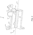
- FIG. 2 shows an exemplary implementation of the bi-directional oil-flow adapter 115 in accordance with an embodiment of the disclosure.
- the bi-directional oil-flow adapter 115 can include a flange 305 that can be used to mechanically couple the bi-directional oil-flow adapter 115 to the valve-controlled port 110 (shown in FIG. 1 ).
- the flange 305 can be located at one end of a cylindrical body portion 208 that includes an opening 206 through which oil enters the bi-directional oil-flow adapter 115 from the valve-controlled port 110.
- the oil outlet port 119 can be located at an opposing end of the cylindrical body portion 208.
- Also located at the opposing end of the cylindrical body portion 208 can be an oil inlet port 128 that is coupled to the pump 128 (via a control valve 134 as shown in FIG. 1 ).
- the cylindrical internal surface of the cylindrical body portion 208 can constitute a peripheral circumference of the first conduit 116.
- Arranged concentric to the cylindrically-shaped internal surface of the cylindrically-shaped body portion 208 (i.e., the first conduit 116) can be a cylindrically-shaped pipe that constitutes the second conduit 117. It can be understood that each of a longitudinal axis of the first conduit 116 and a longitudinal axis of the second conduit 117 can coincide with a longitudinal axis 209 of the bi-directional oil-flow adapter 115.
- the pressure sensor 120 can be coupled into the bi-directional oil-flow adapter 115 at one of various openings provided in the cylindrical body portion 208, such as the pressure monitoring port 118 located near the oil outlet port 119.
- FIG. 3 illustrates an example first oil flow characteristic 310 when oil is drawn through an opening 305 in the valve-controlled port 110, when the valve-controlled port 110 is coupled to the transformer housing 106, according to an embodiment of the disclosure.
- the valve-controlled port 110 can include a gate valve 315 that blocks the flow of oil when actuated to block the internal opening 320.
- the gate valve 315 when the gate valve 315 is actuated to unblock the internal opening 320, oil can flow through the valve-controlled port 110 along the first oil flow characteristic 310 (indicated by the dashed line) and out through the opening 330 (into the bi-directional oil-flow adapter 115).
- an area 325 of the valve-controlled port 110 can accumulate stagnant oil as a result of being located away from the main oil flow path (designated by the first oil flow characteristic 310). It can be undesirable that the oil remains stagnant in nooks and crannies, such as the area 325, for various reasons. One of these reasons can be attributed to the stagnant oil constituting a stale oil sample that does not replicate the characteristics of the oil contained inside the transformer housing 106 and can provide misleading results if drawn through the valve-controlled port 110 and into the bi-directional oil-flow adapter 115 for sampling purposes.
- FIG. 4 illustrates an example second oil flow characteristic 410 when the sampled oil is forcefully injected into the valve-controlled port 110 via the opening 330 from the bi-directional oil-flow adapter 115, according to an embodiment of the disclosure.
- the forceful injection of the sample oil (by using the pump 128 shown in FIG. 1 ) can flush out any stagnant oil that may be present in locations such as the area 325 thereby ensuring that the next oil sample drawn from the transformer housing 106 via the valve-controlled port 110 more accurately represents the oil contained inside the transformer housing 106.
- the forceful injection of the sample oil can also flush out stale oil from other locations such as in the bi-directional oil-flow adapter 115, and/or in pipework associated with the bi-directional oil-flow adapter 115 and/or the valve-controlled port 110.
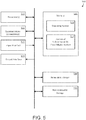
- FIG. 5 illustrates an example computer 140 incorporating one or more processors, such as a processor 505, for executing an oil sampling procedure upon the transformer 105 by using a bi-directional oil-flow adapter 115 in accordance with an embodiment of the disclosure.
- the processor 505 can be configured to communicatively cooperate with various elements contained in the system 100 shown in FIG. 1 , including a memory 525.
- the processor 505 can be implemented and operated using appropriate hardware, software, firmware, or combinations thereof.
- Software or firmware implementations can include computer-executable or machine-executable instructions written in any suitable programming language to perform the various functions described.
- instructions associated with a function block language can be stored in the memory 525 and executed by the processor 505.
- the memory 525 can be used to store program instructions that are loadable and executable by the processor 505, as well as to store data generated during the execution of these programs.
- the memory 525 can be volatile (such as random access memory (RAM)) and/or non-volatile (such as read-only memory (ROM), flash memory, etc.).
- the memory devices can also include additional removable storage 530 and/or non-removable storage 535 including, but not limited to, magnetic storage, optical disks, and/or tape storage.
- the disk drives and their associated computer-readable media can provide non-volatile storage of computer-readable instructions, data structures, program modules, and other data.
- the memory 525 can include multiple different types of memory, such as static random access memory (SRAM), dynamic random access memory (DRAM), or ROM.
- SRAM static random access memory
- DRAM dynamic random access memory
- ROM read-only memory
- the memory 525, the removable storage, and the non-removable storage are all examples of non-transient computer-readable storage media.
- Such non-transient computer-readable storage media can be implemented in any method or technology for storage of information such as computer-readable instructions, data structures, program modules or other data. Additional types of non-transient computer storage media that can be present include, but are not limited to, programmable random access memory (PRAM), SRAM, DRAM, ROM, electrically erasable programmable read-only memory (EEPROM), compact disc read-only memory (CD-ROM), digital versatile discs (DVD) or other optical storage, magnetic cassettes, magnetic tapes, magnetic disk storage or other magnetic storage devices, or any other medium which can be used to store the desired information and which can be accessed by the processor 505. Combinations of any of the above should also be included within the scope of non-transient computer-readable media.
- the memory 525 can include, but is not limited to, an operating system (OS) and one or more application programs or services for implementing the features and aspects disclosed herein.
- OS operating system
- application programs or services can include software and/or firmware portions of the system 100 that is associated with the bi-directional oil-flow adapter 527, such as for processing one or more signals provided by the DGA 135, actuating various automatically controlled valves (such as the valve 127, for example), and processing various alarm/warning/status signals provided by the malfunction detection system 130.
- FIG. 6 illustrates an example flowchart of a method for executing an oil sampling procedure upon a transformer by using a bi-directional oil-flow adapter 115 in accordance with an embodiment of the disclosure.
- Block 605 pertains to providing a bi-directional oil-flow adapter 115 connected to a valve-controlled port 110 of a transformer.
- Block 610 pertains to providing a dissolved gas analyzer 135 that is coupled to an oil outlet port 119 of the bi-directional oil-flow adapter 115.
- a gas sensor assembly 125 can be optionally included to provide to the DGA 135, one or more signals indicative of a rate of release of at least one gas contained in an oil sample.
- Block 615 pertains to drawing oil from the valve-controlled port 110 via a first conduit 116 of the bi-directional oil-flow adapter 115, the first conduit 116 having a first cross-sectional area that is selected to provide a first oil flow velocity.
- Block 620 pertains to providing at least one oil sample to the DGA 135, via the oil outlet port 119 that is located at one end of the first conduit 116.
- Block 625 pertains to analyzing, in the DGA 135, the at least one oil sample for evaluating at least one gas content in the at least one oil sample. A number of oil samples can be analyzed by the DGA 135 over a period of time.
- Block 630 pertains to transferring the at least one oil sample from the DGA 135 to a purge tank 145 containing a volume of oil.
- Block 635 pertains to pumping at least a portion of the volume of oil from the purge tank 145 and into the valve-controlled port 110 of the transformer 105 via an oil inlet port 138 located at one end of a second conduit 117 of the bi-directional oil-flow adapter 115, the second conduit 117 having a second cross-sectional area that is smaller than the first cross-sectional area of the first conduit 116, the second cross-sectional area providing a second oil flow velocity that is greater than the first oil flow velocity.
Landscapes
- Engineering & Computer Science (AREA)
- Power Engineering (AREA)
- Chemical & Material Sciences (AREA)
- Health & Medical Sciences (AREA)
- Life Sciences & Earth Sciences (AREA)
- Physics & Mathematics (AREA)
- General Physics & Mathematics (AREA)
- Pathology (AREA)
- Immunology (AREA)
- Analytical Chemistry (AREA)
- Biochemistry (AREA)
- General Health & Medical Sciences (AREA)
- Food Science & Technology (AREA)
- Medicinal Chemistry (AREA)
- General Engineering & Computer Science (AREA)
- Mechanical Engineering (AREA)
- Chemical Kinetics & Catalysis (AREA)
- General Chemical & Material Sciences (AREA)
- Oil, Petroleum & Natural Gas (AREA)
- Combustion & Propulsion (AREA)
- Fluid Mechanics (AREA)
- Sampling And Sample Adjustment (AREA)
- Housings And Mounting Of Transformers (AREA)
- Transformer Cooling (AREA)
Abstract
Description
- This disclosure relates to a power transformer, and more particularly, to a bi-directional oil flow adapter for attaching to a valve-controlled port of a power transformer.
- A power transformer typically includes a housing containing oil that is used to cool the coils of the power transformer. Over time, the oil deteriorates and becomes less efficient in operating as a cooling agent. Consequently, the oil contained inside the power transformer is periodically replaced with fresh oil. The oil replacement procedure is generally carried out by injecting fresh oil into a first valve-controlled port of the housing while draining out the old oil via a second valve-controlled port of the housing. Using such a draining procedure ensures that the fresh oil flushes out the old oil. However, this operation requires that various fixtures (piping, insulation, gaskets, tanks etc.) be provided on each of the two valve-controlled ports and, thus, reserved for performing oil replacement procedures.
- Certain embodiments of the disclosure can provide a technical effect and/or solution to provide a bi-directional oil-flow adapter that can be attached to a valve-controlled port that is a part of a transformer housing in which oil is contained for purposes of cooling various parts of a transformer, such as a primary coil, a secondary coil, and a core. The bi-directional oil-flow adapter not only allows for an oil sample to be drawn out of the transformer housing via the valve-controlled port for various purposes, but also allows for the oil sample to combined with an additional volume of oil if so desired and used for flushing the valve-controlled port. The flushing can be carried out to ensure that a subsequent oil sample is different than a current oil sample. The one or more oil samples drawn out of the transformer can be provided to a dissolved gas analyzer (DGA) for purposes of detecting and analyzing one or more gases that may be present in the oil sample. The presence and/or concentration of these one or more gases can be used to detect a contaminant in the oil sample and/or to determine a level of contamination of the oil sample.
- Accordingly, in one exemplary embodiment of the disclosure, a system can include a transformer, a bi-directional oil-flow adapter, and a dissolved gas analyzer. The transformer can include a valve-controlled port for use when accessing oil contained inside the transformer. The bi-directional oil-flow adapter can be attached to the valve-controlled port and can include an oil outlet port, a first conduit contained inside the bi-directional oil-flow adapter, an oil inlet port, and a second conduit contained inside the bi-directional oil-flow adapter. The oil outlet port can be configured to output an oil sample acquired from the transformer via the valve-controlled port and the bi-directional oil-flow adapter when the bi-directional oil-flow adapter can be attached to the valve-controlled port. The first conduit contained inside the bi-directional oil-flow adapter has a first cross-sectional area that is selected to provide a first oil flow velocity to the oil sample when flowing from the valve-controlled port and through the bi-directional oil-flow adapter to the oil outlet port. The oil inlet port can be configured to accept an inflow of a volume of oil into the bi-directional oil-flow adapter. The second conduit has a second cross-sectional area that is smaller than the first cross-sectional area, the second cross-sectional area selected to provide a second oil flow velocity to the volume of oil when flowing from the oil inlet port and through the bi-directional oil-flow adapter into the valve-controlled port. The second oil flow velocity is higher than the first oil flow velocity. The dissolved gas analyzer can be coupled to the oil outlet port of the bi-directional oil-flow adapter and is operable to analyze the oil sample for evaluating at least one gas content of the oil sample.
- According to another exemplary embodiment of the disclosure, a bi-directional oil-flow adapter that is attachable to a valve-controlled port of a transformer can include an oil outlet port, a first conduit contained inside the bi-directional oil-flow adapter, an oil inlet port, and a second conduit contained inside the bi-directional oil-flow adapter. The oil outlet port can be configured to output an oil sample acquired from the transformer via the valve-controlled port and the bi-directional oil-flow adapter when the bi-directional oil-flow adapter is attached to the valve-controlled port. The first conduit has a first cross-sectional area that is selected to provide a first oil flow velocity to the oil sample when flowing from the valve-controlled port and through the bi-directional oil-flow adapter to the oil outlet port. The oil inlet port can be configured to accept an inflow of a volume of oil into the bi-directional oil-flow adapter. The second conduit has a second cross-sectional area that is smaller than the first cross-sectional area, the second cross-sectional area selected to provide a second oil flow velocity to the volume of oil when flowing from the oil inlet port and through the bi-directional oil-flow adapter into the valve-controlled port. The second oil flow velocity is higher than the first oil flow velocity.
- According to yet another exemplary embodiment of the disclosure, a method can include providing a bi-directional oil-flow adapter connected to a valve-controlled port of a transformer; providing a dissolved gas analyzer that is coupled to an oil outlet port of the bi-directional oil-flow adapter; drawing oil from the valve-controlled port via a first conduit of the bi-directional oil-flow adapter, the first conduit having a first cross-sectional area that is selected to provide a first oil flow velocity; providing at least one oil sample to the dissolved gas analyzer, via the oil outlet port that is located at one end of the first conduit; analyzing, in the dissolved gas analyzer, the at least one oil sample for evaluating at least one gas content in the at least one oil sample; transferring the at least one oil sample from the dissolved gas analyzer to a purge tank containing a volume of oil; and pumping at least a portion of the volume of oil from the purge tank and into the valve-controlled port of the transformer via an oil inlet port located at one end of a second conduit of the bi-directional oil-flow adapter, the second conduit having a second cross-sectional area that is smaller than the first cross-sectional area of the first conduit, the second cross-sectional area providing a second oil flow velocity that is greater than the first oil flow velocity.
- Other embodiments and aspects of the disclosure will become apparent from the following description taken in conjunction with the following drawings.
- Having thus described the disclosure in general terms, reference will now be made to the accompanying drawings, which are not necessarily drawn to scale, and wherein:
-
FIG. 1 shows an exemplary system that includes a transformer and a bi-directional oil-flow adapter attached to a valve-controlled port of a transformer housing in which some components of the transformer are housed, in accordance with an embodiment of the disclosure. -
FIG. 2 shows an exemplary implementation of a bi-directional oil-flow adapter in accordance with an embodiment of the disclosure. -
FIG. 3 illustrates a first oil flow characteristic when oil is drawn through the valve-controlled port by using the bi-directional oil-flow adapter in accordance with an embodiment of the disclosure. -
FIG. 4 illustrates a second oil flow characteristic when oil is injected into the valve-controlled port by using the bi-directional oil-flow adapter in accordance with an embodiment of the disclosure. -
FIG. 5 illustrates an example computer incorporating a processor for executing an oil sampling procedure upon a transformer by using a bi-directional oil-flow adapter in accordance with an embodiment of the disclosure. -
FIG. 6 illustrates an example flowchart of a method for executing an oil sampling procedure upon a transformer by using a bi-directional oil-flow adapter in accordance with an embodiment of the disclosure. - The disclosure will be described more fully hereinafter with reference to the accompanying drawings, in which exemplary embodiments of the disclosure are shown. This disclosure may, however, be embodied in many different forms and should not be construed as limited to the exemplary embodiments set forth herein; rather, these embodiments are provided so that this disclosure will satisfy applicable legal requirements. Like numbers refer to like elements throughout. It should be understood that certain words and terms are used herein solely for convenience and such words and terms should be interpreted as referring to various objects and actions that are generally understood in various forms and equivalencies by persons of ordinary skill in the art. It should be understood that the words "example" and "exemplary" as used herein are intended to be non-exclusionary and non-limiting in nature. More particularly, the word "exemplary" as used herein indicates one among several examples, and it should be understood that no undue emphasis or preference is being directed to the particular example being described.
- Attention is first drawn to
FIG. 1 , which shows anexemplary system 100 that can include atransformer 105 and a bi-directional oil-flow adapter 115 attached to a valve-controlledport 110 of atransformer housing 106 inside which various components of thetransformer 105 are housed. Thetransformer housing 106 also contains oil that is used for cooling the various components of thetransformer 105 contained inside, such as a primary coil and/or a secondary coil. The valve-controlledport 110 can be used in accordance with traditional practice for draining out old oil while replacing the old oil with fresh oil via another valve-controlled port (not shown). As can be understood, the valve-controlledport 110 can incorporate various traditional elements such as a gate valve, a butterfly valve, or a globe valve, each of which can be manually operated using a control wheel or lever, such as thecontrol wheel 111 shown inFIG. 1 . - In accordance with certain embodiments of the disclosure, the bi-directional oil-
flow adapter 115 not only allows for an oil sample to be extracted out of thetransformer housing 106 via the valve-controlledport 110 for various purposes, but also allows for the oil sample to be used in a flushing procedure for flushing the valve-controlled port. The flushing, which can be used to ensure that the contents in a subsequent oil sample are different than in a current oil sample, can be carried out by combining the extracted oil sample with an additional volume of oil stored in apurge tank 145, as will be described below in more detail. - The oil sample that is extracted from the
transformer housing 106 via the valve-controlledport 110, can flow through afirst conduit 116 inside the bi-directional oil-flow adapter 115 and out of anoil outlet port 119 of the bi-directional oil-flow adapter 115. Thefirst conduit 116 can have a first cross-sectional area that can be specifically selected to provide a first oil flow velocity to the oil sample when flowing from the valve-controlledport 110 and through the bi-directional oil-flow adapter 115 to theoil outlet port 119. - In a procedure that will be described below in more detail, the oil sample can be transferred to a
purge tank 145 after a dissolved gas analysis of the oil sample is carried out. The oil sample can be subsequently combined with a volume of oil that is optionally added to thepurge tank 145, and forcefully reintroduced into the valve-controlledport 110 through aninlet port 138 for purposes of purging the valve-controlledport 110 of old and/or stagnant oil. The reintroduction procedure can be carried out by using apump 128 to forcefully inject the oil sample combined, if so desired, with the volume of oil stored in thepurge tank 145 back into the valve-controlledport 110 via asecond conduit 117 contained inside the bi-directional oil-flow adapter 115. Thesecond conduit 117 can have a second cross-sectional area that is relatively smaller than the first cross-sectional area of thefirst conduit 116 and can be specifically selected to provide a second oil flow velocity to the oil sample when flowing through the bi-directional oil-flow adapter 115 and into the valve-controlledport 110. The smaller cross-sectional area of thesecond conduit 117 can ensure, in certain instances, that the second oil flow velocity directed towards the valve-controlledport 110 is relatively higher than the first oil flow velocity out of the valve-controlledport 110. - An
oil pipe section 121 can be coupled to theoutlet port 119 for transporting the oil sample from the bi-directional oil-flow adapter 115 to agas sensor assembly 125. Thegas sensor assembly 125, which is an optional element and can be omitted in some implementations, can be configured to detect a rate of release of at least one gas contained in the oil sample and to generate one or more sensor signals that can be provided to a dissolved gas analyzer (DGA) 135 via a signal line 123. For example, thegas sensor assembly 125 can detect a rate of release of a gas contained in the oil sample and determine that the oil sample has a level of contamination that may warrant an analysis procedure in theDGA 135. The various gases processed by thegas sensor assembly 125 can include a family of gases, including a family of low-k gases such as hydrogen and/or carbon monoxide. - The
oil pipe section 121 can be further coupled to acontrol valve 127 that can be activated to route the oil sample into the DGA 135 via anoil pipe section 124. In one example implementation, the oil sample can be drawn into theDGA 135 via theoil pipe section 124, by using a pump (not shown) that is located inside theDGA 135. - The
DGA 135 can perform a gas analysis procedure to identify and/or measure the concentration of various gases in the oil sample so as to assess the quality of the oil sample. For example, the gas analysis procedure can be used to determine if the oil contained inside thetransformer housing 106 warrants carrying out an oil replacement. Gas analysis procedures associated with theDGA 135 are known in the art and any number of such procedures can be performed by theDGA 135. In any instance, the results of the gas analysis procedure(s) performed by theDGA 135 can be provided to acomputer 140 that is communicatively coupled to theDGA 135. Thecomputer 140 can use the results of the gas analysis procedures for various purposes, such as to provide alarms, messages, and alerts to personnel associated with the transformer 105 (a technician, a manager, a data analyst etc.). - After executing one or more gas analysis procedures upon the oil sample, the
DGA 135 can transfer the oil sample to thepurge tank 145 via anoil pipe section 136 where oil flow can be controlled by using acontrol valve 129. It should be understood that the gas analysis procedure carried out by theDGA 135 can be repeated on several oil samples provided via the bi-directional oil-flow adapter 115. The several oil samples can be obtained over a period of time in a periodic or intermittent manner, as desired. - The
purge tank 145 can be configured to not only store the oil sample provided by theDGA 135 via theoil pipe section 136, but to also store an additional volume of oil that can be directed into thepurge tank 145 via anoil pipe section 126. Specifically, thecontrol valve 127, which can be a directional valve to route oil into at least two different oil pipe sections, can not only be actuated to route the oil sample from the bi-directional oil-flow adapter 115 into theDGA 135, but can be also actuated to alternatively route an amount of oil (other than the oil sample) from the bi-directional oil-flow adapter 115 into thepurge tank 145. The additional volume of oil can be combined with the oil sample provided by theDGA 135, if so desired, and used to forcefully purge the valve-controlledport 110 of old and/or stagnant oil. Thepump 128 and a control valve 134 (optional) can be used for this purpose. - The
purge tank 145 can include various elements such as afirst level sensor 132 for sensing an oil level exceeding a high threshold level, and asecond level sensor 133 for sensing an oil level dropping below a low threshold level. An air inlet assembly can also be provided in the form of anair inlet pipe 137 and acontrol valve 131 that can be actuated to allow air to enter thepurge tank 145 via theair inlet pipe 137, if so desired. The air can be provided for example, when the oil stored in thepurge tank 145 is being pumped out by thepump 128. - Attention is now drawn to a
malfunction detection system 130 and apressure sensor 120 shown inFIG. 1 , each of which can be optionally included in some example implementations. Themalfunction detection system 130 can be coupled to asignal line 122 that can carry one or more oil pressure signals or gas level indication signals from thepressure sensor 120 to the dissolved gas analyzer (DGA) 135. Thepressure sensor 120 can be attached to the bi-directional oil-flow adapter 115 (at a pressure monitoring port 118) for monitoring an oil pressure and/or a gas pressure in the bi-directional oil-flow adapter 115. Changes in the oil pressure and/or the gas pressure can be indicative of various malfunctions, such as a malfunction in the valve-controlledport 110 and/or in the bi-directional oil-flow adapter 115. Upon detecting such a malfunction (based on processing the signal(s) carried on signal line 122), themalfunction detection system 130 can transmit various alarms, messages, and/or alerts to various personnel associated with the transformer 105 (such as a technician, a manager, and/or a data analyst). In some implementations, themalfunction detection system 130 can be communicatively coupled to thecomputer 140 for facilating and/or processing of the various alarms, messages, and/or alerts by thecomputer 140. -
FIG. 2 shows an exemplary implementation of the bi-directional oil-flow adapter 115 in accordance with an embodiment of the disclosure. In this exemplary implementation, the bi-directional oil-flow adapter 115 can include aflange 305 that can be used to mechanically couple the bi-directional oil-flow adapter 115 to the valve-controlled port 110 (shown inFIG. 1 ). Theflange 305 can be located at one end of acylindrical body portion 208 that includes anopening 206 through which oil enters the bi-directional oil-flow adapter 115 from the valve-controlledport 110. Theoil outlet port 119 can be located at an opposing end of thecylindrical body portion 208. Also located at the opposing end of thecylindrical body portion 208 can be anoil inlet port 128 that is coupled to the pump 128 (via a control valve 134 as shown inFIG. 1 ). - The cylindrical internal surface of the
cylindrical body portion 208 can constitute a peripheral circumference of thefirst conduit 116. Arranged concentric to the cylindrically-shaped internal surface of the cylindrically-shaped body portion 208 (i.e., the first conduit 116) can be a cylindrically-shaped pipe that constitutes thesecond conduit 117. It can be understood that each of a longitudinal axis of thefirst conduit 116 and a longitudinal axis of thesecond conduit 117 can coincide with alongitudinal axis 209 of the bi-directional oil-flow adapter 115. - The
pressure sensor 120 can be coupled into the bi-directional oil-flow adapter 115 at one of various openings provided in thecylindrical body portion 208, such as thepressure monitoring port 118 located near theoil outlet port 119. -
FIG. 3 illustrates an example first oil flow characteristic 310 when oil is drawn through anopening 305 in the valve-controlledport 110, when the valve-controlledport 110 is coupled to thetransformer housing 106, according to an embodiment of the disclosure. In this exemplary implementation, the valve-controlledport 110 can include agate valve 315 that blocks the flow of oil when actuated to block theinternal opening 320. On the other hand, when thegate valve 315 is actuated to unblock theinternal opening 320, oil can flow through the valve-controlledport 110 along the first oil flow characteristic 310 (indicated by the dashed line) and out through the opening 330 (into the bi-directional oil-flow adapter 115). As can be understood from the firstoil flow characteristic 310, anarea 325 of the valve-controlledport 110 can accumulate stagnant oil as a result of being located away from the main oil flow path (designated by the first oil flow characteristic 310). It can be undesirable that the oil remains stagnant in nooks and crannies, such as thearea 325, for various reasons. One of these reasons can be attributed to the stagnant oil constituting a stale oil sample that does not replicate the characteristics of the oil contained inside thetransformer housing 106 and can provide misleading results if drawn through the valve-controlledport 110 and into the bi-directional oil-flow adapter 115 for sampling purposes. -
FIG. 4 illustrates an example second oil flow characteristic 410 when the sampled oil is forcefully injected into the valve-controlledport 110 via theopening 330 from the bi-directional oil-flow adapter 115, according to an embodiment of the disclosure. The forceful injection of the sample oil (by using thepump 128 shown inFIG. 1 ) can flush out any stagnant oil that may be present in locations such as thearea 325 thereby ensuring that the next oil sample drawn from thetransformer housing 106 via the valve-controlledport 110 more accurately represents the oil contained inside thetransformer housing 106. In addition to flushing the valve-controlledport 110, the forceful injection of the sample oil can also flush out stale oil from other locations such as in the bi-directional oil-flow adapter 115, and/or in pipework associated with the bi-directional oil-flow adapter 115 and/or the valve-controlledport 110. -
FIG. 5 illustrates anexample computer 140 incorporating one or more processors, such as aprocessor 505, for executing an oil sampling procedure upon thetransformer 105 by using a bi-directional oil-flow adapter 115 in accordance with an embodiment of the disclosure. Theprocessor 505 can be configured to communicatively cooperate with various elements contained in thesystem 100 shown inFIG. 1 , including amemory 525. Theprocessor 505 can be implemented and operated using appropriate hardware, software, firmware, or combinations thereof. Software or firmware implementations can include computer-executable or machine-executable instructions written in any suitable programming language to perform the various functions described. In one embodiment, instructions associated with a function block language can be stored in thememory 525 and executed by theprocessor 505. - The
memory 525 can be used to store program instructions that are loadable and executable by theprocessor 505, as well as to store data generated during the execution of these programs. Depending on the configuration and type of thesystem 100, thememory 525 can be volatile (such as random access memory (RAM)) and/or non-volatile (such as read-only memory (ROM), flash memory, etc.). In some embodiments, the memory devices can also include additionalremovable storage 530 and/ornon-removable storage 535 including, but not limited to, magnetic storage, optical disks, and/or tape storage. The disk drives and their associated computer-readable media can provide non-volatile storage of computer-readable instructions, data structures, program modules, and other data. In some implementations, thememory 525 can include multiple different types of memory, such as static random access memory (SRAM), dynamic random access memory (DRAM), or ROM. - The
memory 525, the removable storage, and the non-removable storage are all examples of non-transient computer-readable storage media. Such non-transient computer-readable storage media can be implemented in any method or technology for storage of information such as computer-readable instructions, data structures, program modules or other data. Additional types of non-transient computer storage media that can be present include, but are not limited to, programmable random access memory (PRAM), SRAM, DRAM, ROM, electrically erasable programmable read-only memory (EEPROM), compact disc read-only memory (CD-ROM), digital versatile discs (DVD) or other optical storage, magnetic cassettes, magnetic tapes, magnetic disk storage or other magnetic storage devices, or any other medium which can be used to store the desired information and which can be accessed by theprocessor 505. Combinations of any of the above should also be included within the scope of non-transient computer-readable media. - Turning to the contents of the
memory 525, thememory 525 can include, but is not limited to, an operating system (OS) and one or more application programs or services for implementing the features and aspects disclosed herein. Such applications or services can include software and/or firmware portions of thesystem 100 that is associated with the bi-directional oil-flow adapter 527, such as for processing one or more signals provided by theDGA 135, actuating various automatically controlled valves (such as thevalve 127, for example), and processing various alarm/warning/status signals provided by themalfunction detection system 130. -
FIG. 6 illustrates an example flowchart of a method for executing an oil sampling procedure upon a transformer by using a bi-directional oil-flow adapter 115 in accordance with an embodiment of the disclosure. The various blocks of the example flowchart are described here with reference toFIG. 1 .Block 605 pertains to providing a bi-directional oil-flow adapter 115 connected to a valve-controlledport 110 of a transformer.Block 610 pertains to providing a dissolvedgas analyzer 135 that is coupled to anoil outlet port 119 of the bi-directional oil-flow adapter 115. Agas sensor assembly 125 can be optionally included to provide to theDGA 135, one or more signals indicative of a rate of release of at least one gas contained in an oil sample.Block 615 pertains to drawing oil from the valve-controlledport 110 via afirst conduit 116 of the bi-directional oil-flow adapter 115, thefirst conduit 116 having a first cross-sectional area that is selected to provide a first oil flow velocity.Block 620 pertains to providing at least one oil sample to theDGA 135, via theoil outlet port 119 that is located at one end of thefirst conduit 116.Block 625 pertains to analyzing, in theDGA 135, the at least one oil sample for evaluating at least one gas content in the at least one oil sample. A number of oil samples can be analyzed by theDGA 135 over a period of time.Block 630 pertains to transferring the at least one oil sample from theDGA 135 to apurge tank 145 containing a volume of oil.Block 635 pertains to pumping at least a portion of the volume of oil from thepurge tank 145 and into the valve-controlledport 110 of thetransformer 105 via anoil inlet port 138 located at one end of asecond conduit 117 of the bi-directional oil-flow adapter 115, thesecond conduit 117 having a second cross-sectional area that is smaller than the first cross-sectional area of thefirst conduit 116, the second cross-sectional area providing a second oil flow velocity that is greater than the first oil flow velocity. - Many modifications and other embodiments of the example descriptions set forth herein to which these descriptions pertain will come to mind having the benefit of the teachings presented in the foregoing descriptions and the associated drawings. Thus, it will be appreciated the disclosure may be embodied in many forms and should not be limited to the exemplary embodiments described above. Therefore, it is to be understood that the disclosure is not to be limited to the specific embodiments disclosed and that modifications and other embodiments are intended to be included within the scope of the appended claims. Although specific terms are employed herein, they are used in a generic and descriptive sense only and not for purposes of limitation.
Claims (17)
- A bi-directional oil-flow adapter that is attachable to a valve-controlled port (110) of a transformer (105), the bi-directional oil-flow adapter (115) comprising:an oil outlet port (119) configured to output an oil sample acquired from the transformer (105) via the valve-controlled port (110) and the bi-directional oil-flow adapter (115) when the bi-directional oil-flow adapter (115) is attached to the valve-controlled port (110);a first conduit (116) contained inside the bi-directional oil-flow adapter (115), the first conduit (116) having a first cross-sectional area that is selected to provide a first oil flow velocity to the oil sample when flowing from the valve-controlled port (110) and through the bi-directional oil-flow adapter (115) to the oil outlet port (119);an oil inlet port (138) configured to accept an inflow of a volume of oil into the bi-directional oil-flow adapter (115); anda second conduit (117) contained inside the bi-directional oil-flow adapter (115), the second conduit (117) having a second cross-sectional area that is smaller than the first cross-sectional area, the second cross-sectional area selected to provide a second oil flow velocity to the volume of oil when flowing from the oil inlet port (138) and through the bi-directional oil-flow adapter (115) into the valve-controlled port (110), the second oil flow velocity higher than the first oil flow velocity.
- The bi-directional oil-flow adapter of claim 1, wherein each of a longitudinal axis of the first conduit (116) and a longitudinal axis of the second conduit (117) coincides with a longitudinal axis of the bi-directional oil-flow adapter (115).
- The bi-directional oil-flow adapter of claim 1 or 2, wherein the first conduit (116) is arranged concentric to the second conduit (117).
- The bi-directional oil-flow adapter of any of claims 1 to 3, further comprising a pressure sensor (120) operable to obtain an oil pressure reading of oil contained in the bi-directional oil-flow adapter (115).
- A system comprising:a transformer (105) comprising a valve-controlled port (110) for use when accessing oil contained inside the transformer (105);a bi-directional oil-flow adapter (115) that is attachable to the valve-controlled port (110), the bi-directional oil-flow adapter as defined in any of claims 1 to 4; anda dissolved gas analyzer (135) coupled to the oil outlet port (138) of the bi-directional oil-flow adapter (115), the dissolved gas analyzer (135) operable to analyze the oil sample for evaluating at least one gas content of the oil sample.
- The system of claim 5, further comprising:a pressure sensor (120) attached to the bi-directional oil-flow adapter (115); anda malfunction detection system (130) coupled to at least one of the pressure sensor (120) or the dissolved gas analyzer (135), the malfunction detection system (130) configured to obtain at least one of an oil pressure reading from the pressure sensor (120) or a gas level indication from the dissolved gas analyzer (135) and to use the at least one of the oil pressure reading or the gas level indication to determine a malfunctioning of the valve-controlled port (110).
- The system of claim 5 or 6, further comprising:a gas sensor assembly (125) coupled to the oil outlet port (138) of the bi-directional oil-flow adapter (115), the gas sensor assembly (125) configured to detect a rate of release of at least one gas contained in the oil sample and to generate one or more sensor signals that are provided to the dissolved gas analyzer (135).
- The system of claim 7, wherein the at least one gas is a low-k gas selected from a family of gases, the family of gases comprising hydrogen and carbon monoxide.
- The system of any of claims 5 to 8, further comprising:a purge tank (145) configured to store the volume of oil; anda pump (128) that is operable to pump the volume of oil from the purge tank (145) and into the oil inlet port (138) of the bi-directional oil-flow adapter (115).
- The system of claim 9, wherein the purge tank (145) is further configured to store the oil sample as a part of the volume of oil, after analyzing by the dissolved gas analyzer (135).
- A method comprising:providing a bi-directional oil-flow adapter (115) connected to a valve-controlled port (110) of a transformer (105);providing a dissolved gas analyzer (135) that is coupled to an oil outlet port (119) of the bi-directional oil-flow adapter (115);drawing oil from the valve-controlled port (110) via a first conduit (116) of the bi-directional oil-flow adapter (115), the first conduit (116) having a first cross-sectional area that is selected to provide a first oil flow velocity;providing at least one oil sample to the dissolved gas analyzer (135), via the oil outlet port (119) that is located at one end of the first conduit (116);analyzing, in the dissolved gas analyzer (135), the at least one oil sample for evaluating at least one gas content in the at least one oil sample;transferring the at least one oil sample from the dissolved gas analyzer (135) to a purge tank (145) containing a volume of oil; andpumping at least a portion of the volume of oil from the purge tank (145) and into the valve-controlled port (110) of the transformer (105) via an oil inlet port (138) located at one end of a second conduit (117) of the bi-directional oil-flow adapter (115), the second conduit (117) having a second cross-sectional area that is smaller than the first cross-sectional area of the first conduit (116), the second cross-sectional area providing a second oil flow velocity that is greater than the first oil flow velocity.
- The method of claim 11, wherein the at least one gas content in the at least one oil sample is indicative of a contaminant in oil contained inside the transformer (105).
- The method of claim 11 or 12, wherein the second oil flow velocity is directed at purging oil from an area inside at least one of the bi-directional oil-flow adapter (115), the valve-controlled port (110), or pipework associated with at least one of the bi-directional oil-flow adapter (115) or the valve-controlled port (110).
- The method of any of claims 11 to 13, wherein the at least one oil sample comprises a plurality of oil samples obtained by the dissolved gas analyzer (135) from the transformer (105) over a period of time.
- The method of any of claims 11 to 14, further comprising:coupling a pressure sensor to a pressure (120) sensing port of the bi-directional oil-flow adapter (115);using the pressure sensor (120) to obtain an oil pressure reading of oil contained in the bi-directional oil-flow adapter (115); anddetermining from the oil pressure reading, a malfunctioning of the valve-controlled port (110).
- The method of claim 15, wherein the malfunctioning of the valve-controlled port (110) is characterized by at least one of the oil pressure reading exceeding a first threshold pressure or the oil pressure reading falling below a second threshold pressure.
- The method of any of claims 11 to 16, further comprising:detecting a rate of release of at least one gas contained in the at least one oil sample and generating one or more sensor signals that are coupled into the dissolved gas analyzer (135); anddetecting a malfunctioning of the valve-controlled port (110) based at least in part on the rate of release of the at least one gas contained in the at least one oil sample.
Applications Claiming Priority (1)
| Application Number | Priority Date | Filing Date | Title |
|---|---|---|---|
| US15/250,162 US10495622B2 (en) | 2016-08-29 | 2016-08-29 | Bi-directional oil-flow adapter for attaching to a valve-controlled port of a transformer |
Publications (2)
| Publication Number | Publication Date |
|---|---|
| EP3291255A1 true EP3291255A1 (en) | 2018-03-07 |
| EP3291255B1 EP3291255B1 (en) | 2020-06-24 |
Family
ID=59745161
Family Applications (1)
| Application Number | Title | Priority Date | Filing Date |
|---|---|---|---|
| EP17185593.5A Active EP3291255B1 (en) | 2016-08-29 | 2017-08-09 | Bi-directional oil-flow adapter attached to a valve controlled port of a transformer |
Country Status (6)
| Country | Link |
|---|---|
| US (1) | US10495622B2 (en) |
| EP (1) | EP3291255B1 (en) |
| JP (1) | JP7277045B2 (en) |
| CN (1) | CN107799275A (en) |
| CA (1) | CA2976664A1 (en) |
| MX (1) | MX375760B (en) |
Cited By (1)
| Publication number | Priority date | Publication date | Assignee | Title |
|---|---|---|---|---|
| FR3142828A1 (en) | 2022-12-05 | 2024-06-07 | Transfo Services | Sensor support for hermetic transformer, associated transformer assembly, safety assembly and transformer installation |
Families Citing this family (12)
| Publication number | Priority date | Publication date | Assignee | Title |
|---|---|---|---|---|
| WO2016179693A1 (en) | 2015-05-11 | 2016-11-17 | 9334-3275 Quebec Inc. | Photoacoustic detector |
| ES3050209T3 (en) * | 2017-09-27 | 2025-12-19 | Cc Jensen As | Vacuum filtration system |
| US10365209B1 (en) * | 2017-11-15 | 2019-07-30 | Morgan Schaffer Ltd. | Apparatus and method for performing dissolved gas analysis on a piece of electrical equipment using resonant photo-acoustic spectroscopy and use thereof |
| KR102014265B1 (en) * | 2018-07-10 | 2019-08-27 | 한국전력공사 | Potable device for storing and supplying standard oil, method for verifying sensor of dissolved gas in oil and diagnosing fault type of transformer using the same |
| CN108735450B (en) * | 2018-07-18 | 2023-06-30 | 中车株洲电机有限公司 | Cooling system for traction transformer of railway vehicle |
| CN110107796B (en) * | 2019-06-06 | 2024-01-02 | 山东洁普斯自动化科技有限公司 | Straight-through type quantitative valve |
| US11639919B1 (en) * | 2019-12-27 | 2023-05-02 | Dynamic Ratings Pty. Ltd. | Headspace gas monitor |
| CN112649254B (en) * | 2021-01-19 | 2025-03-18 | 华北电力科学研究院有限责任公司 | Transformer simulation sampling system and sampling method |
| CN113790399A (en) * | 2021-09-15 | 2021-12-14 | 广东电网有限责任公司 | A kind of transformer oil pressure automatic adjustment device |
| CN114964586B (en) * | 2022-05-16 | 2024-07-09 | 玉环普天单向器有限公司 | Isolator torsion test fixture |
| US12504419B2 (en) | 2023-05-18 | 2025-12-23 | Morgan Schaffer Ltd. | Apparatus, systems and method for monitoring a piece of electrical equipment |
| GB2633357A (en) * | 2023-09-07 | 2025-03-12 | Siemens Energy Global Gmbh & Co Kg | Transformer device, transformer protection and monitoring device and connecting element |
Citations (3)
| Publication number | Priority date | Publication date | Assignee | Title |
|---|---|---|---|---|
| US5271263A (en) * | 1990-04-25 | 1993-12-21 | Gibeault Jean Pierre | Fluid sampler for detection and monitoring of failure conditions in fluid insulated electrical equipment |
| US20080127714A1 (en) * | 2006-12-01 | 2008-06-05 | Josef Altmann | Quantitative Measurement of Production and Consumption of Gases in Power Transformers |
| CN105805403A (en) * | 2016-06-07 | 2016-07-27 | 李奇元 | Oil drain valve for 10KV oil-immersed transformers |
Family Cites Families (13)
| Publication number | Priority date | Publication date | Assignee | Title |
|---|---|---|---|---|
| GB1125437A (en) * | 1964-12-11 | 1968-08-28 | English Electric Co Ltd | Improvements in electrical transformers and reactors |
| JPH03128917U (en) * | 1990-04-06 | 1991-12-25 | ||
| US5070738A (en) * | 1990-06-14 | 1991-12-10 | Morgan Schaffer Systems Incorporated | Device and method for recirculating a stream of fluid from a vessel |
| JPH0673336B2 (en) * | 1992-07-15 | 1994-09-14 | 大阪瓦斯株式会社 | Abnormality prediction system for oil-filled transformer |
| JPH097840A (en) * | 1995-06-19 | 1997-01-10 | Hitachi Ltd | Transformer diagnostic equipment |
| CN101604571B (en) * | 2009-04-15 | 2012-05-16 | 青海送变电工程公司 | totally-enclosed transformer oil treatment system |
| JP2011151236A (en) * | 2010-01-22 | 2011-08-04 | Mitsubishi Electric Corp | Abnormality detection device for pump, and pump controller |
| US8839658B2 (en) * | 2011-03-31 | 2014-09-23 | Qualitrol Company, Llc | Combination of hydrogen and pressure sensors |
| US8511160B2 (en) * | 2011-03-31 | 2013-08-20 | Qualitrol Company, Llc | Combined hydrogen and pressure sensor assembly |
| US9176107B2 (en) * | 2012-02-01 | 2015-11-03 | Lumasense Technologies Holdings, Inc. | System and method for monitoring asset health by dissolved gas measurement |
| KR101327998B1 (en) * | 2012-11-13 | 2013-11-13 | 주식회사 효성 | Apparatus for partial discharge detectin to transformer and transformer having the same |
| CN103257197A (en) * | 2013-05-21 | 2013-08-21 | 杭州申昊信息科技有限公司 | Gassing device for transformer oil monitoring |
| CN103424296B (en) * | 2013-08-19 | 2015-09-23 | 中国科学院电工研究所 | A kind of gases dissolved in insulation oil ON-LINE SEPARATION system of vacuum pump less |
-
2016
- 2016-08-29 US US15/250,162 patent/US10495622B2/en active Active
-
2017
- 2017-08-09 EP EP17185593.5A patent/EP3291255B1/en active Active
- 2017-08-15 JP JP2017156692A patent/JP7277045B2/en active Active
- 2017-08-17 CA CA2976664A patent/CA2976664A1/en active Pending
- 2017-08-28 MX MX2017011057A patent/MX375760B/en active IP Right Grant
- 2017-08-29 CN CN201710757639.8A patent/CN107799275A/en active Pending
Patent Citations (3)
| Publication number | Priority date | Publication date | Assignee | Title |
|---|---|---|---|---|
| US5271263A (en) * | 1990-04-25 | 1993-12-21 | Gibeault Jean Pierre | Fluid sampler for detection and monitoring of failure conditions in fluid insulated electrical equipment |
| US20080127714A1 (en) * | 2006-12-01 | 2008-06-05 | Josef Altmann | Quantitative Measurement of Production and Consumption of Gases in Power Transformers |
| CN105805403A (en) * | 2016-06-07 | 2016-07-27 | 李奇元 | Oil drain valve for 10KV oil-immersed transformers |
Cited By (2)
| Publication number | Priority date | Publication date | Assignee | Title |
|---|---|---|---|---|
| FR3142828A1 (en) | 2022-12-05 | 2024-06-07 | Transfo Services | Sensor support for hermetic transformer, associated transformer assembly, safety assembly and transformer installation |
| EP4383288A1 (en) | 2022-12-05 | 2024-06-12 | Transfo Services | Sensor holder for hermetic transformer, transformer unit, safety unit and associated transformer installation |
Also Published As
| Publication number | Publication date |
|---|---|
| CN107799275A (en) | 2018-03-13 |
| US10495622B2 (en) | 2019-12-03 |
| CA2976664A1 (en) | 2018-02-28 |
| JP7277045B2 (en) | 2023-05-18 |
| JP2018056554A (en) | 2018-04-05 |
| MX375760B (en) | 2025-03-04 |
| EP3291255B1 (en) | 2020-06-24 |
| US20180059087A1 (en) | 2018-03-01 |
| MX2017011057A (en) | 2018-09-20 |
| BR102017017824A2 (en) | 2018-03-13 |
Similar Documents
| Publication | Publication Date | Title |
|---|---|---|
| US10495622B2 (en) | Bi-directional oil-flow adapter for attaching to a valve-controlled port of a transformer | |
| JP6264620B2 (en) | Apparatus and system for sampling fluid and supplying it to an analyzer | |
| JP2013044750A (en) | Method and apparatus for capturing and re-testing excursion material of online toc | |
| KR20140046999A (en) | Apparatus for diagnosing cavitation | |
| Ahmad et al. | Correlation of intra-operative frozen section consultation with the final diagnosis at a referral center in Karachi, Pakistan | |
| US20150355076A1 (en) | Fouling probe for measuring fouling in a process fluid | |
| JP2010127417A (en) | Cavitation diagnosis device | |
| CN114252303B (en) | Smoke detection sampling point | |
| US2928726A (en) | Corrosion testing device | |
| BR102017017824B1 (en) | BIDIRECTIONAL OIL FLOW SYSTEM AND ADAPTER | |
| US10656050B2 (en) | System and method for detecting a leak in an exhaust gas sampling apparatus | |
| Eckert et al. | Corrosion management of MIC contributes to pipeline integrity | |
| US20210294361A1 (en) | Process fluid monitoring system | |
| CN108020499A (en) | New refinery installs pipes Corrosion monitoring test specimen | |
| CN109001347B (en) | VOC on-Line Monitor Device and its fault detection method in flue gas | |
| JP2005214666A (en) | Leak detection apparatus and method | |
| CN112528735A (en) | Automatic pipeline spiral weld flux leakage identification method and device | |
| CN214584398U (en) | Improved DNA sample loading buffer solution preparation device | |
| KR102838354B1 (en) | Metabolites composition for predicting exposure of salinity changing in abalone and method for diagnosing exposure of salinity changing thereof | |
| US7806010B2 (en) | Test port assembly for allowing a test probe to be inserted into a conduit | |
| Eden et al. | Making Credible Corrosion Measurements-Real Corrosion, Real Time | |
| Al-Shahrani et al. | Proactive Corrosion Management for Dead-Legs | |
| Abu Baker et al. | Pro-Active Detection of Potentially Wrong Diagnoses Due to Substantial Changes of Laboratory Measurements | |
| Kapoor | Stability of test criteria and fault hierarchies in software testing | |
| Terpstra et al. | Analysis of Large Numbers of Inspection Data to Assess Corrosion Remnant Life in Offshore Pipework |
Legal Events
| Date | Code | Title | Description |
|---|---|---|---|
| PUAI | Public reference made under article 153(3) epc to a published international application that has entered the european phase |
Free format text: ORIGINAL CODE: 0009012 |
|
| STAA | Information on the status of an ep patent application or granted ep patent |
Free format text: STATUS: THE APPLICATION HAS BEEN PUBLISHED |
|
| AK | Designated contracting states |
Kind code of ref document: A1 Designated state(s): AL AT BE BG CH CY CZ DE DK EE ES FI FR GB GR HR HU IE IS IT LI LT LU LV MC MK MT NL NO PL PT RO RS SE SI SK SM TR |
|
| AX | Request for extension of the european patent |
Extension state: BA ME |
|
| STAA | Information on the status of an ep patent application or granted ep patent |
Free format text: STATUS: REQUEST FOR EXAMINATION WAS MADE |
|
| 17P | Request for examination filed |
Effective date: 20180907 |
|
| RBV | Designated contracting states (corrected) |
Designated state(s): AL AT BE BG CH CY CZ DE DK EE ES FI FR GB GR HR HU IE IS IT LI LT LU LV MC MK MT NL NO PL PT RO RS SE SI SK SM TR |
|
| GRAP | Despatch of communication of intention to grant a patent |
Free format text: ORIGINAL CODE: EPIDOSNIGR1 |
|
| STAA | Information on the status of an ep patent application or granted ep patent |
Free format text: STATUS: GRANT OF PATENT IS INTENDED |
|
| INTG | Intention to grant announced |
Effective date: 20190409 |
|
| GRAJ | Information related to disapproval of communication of intention to grant by the applicant or resumption of examination proceedings by the epo deleted |
Free format text: ORIGINAL CODE: EPIDOSDIGR1 |
|
| STAA | Information on the status of an ep patent application or granted ep patent |
Free format text: STATUS: REQUEST FOR EXAMINATION WAS MADE |
|
| INTC | Intention to grant announced (deleted) | ||
| GRAP | Despatch of communication of intention to grant a patent |
Free format text: ORIGINAL CODE: EPIDOSNIGR1 |
|
| STAA | Information on the status of an ep patent application or granted ep patent |
Free format text: STATUS: GRANT OF PATENT IS INTENDED |
|
| INTG | Intention to grant announced |
Effective date: 20191001 |
|
| GRAS | Grant fee paid |
Free format text: ORIGINAL CODE: EPIDOSNIGR3 |
|
| GRAA | (expected) grant |
Free format text: ORIGINAL CODE: 0009210 |
|
| STAA | Information on the status of an ep patent application or granted ep patent |
Free format text: STATUS: THE PATENT HAS BEEN GRANTED |
|
| AK | Designated contracting states |
Kind code of ref document: B1 Designated state(s): AL AT BE BG CH CY CZ DE DK EE ES FI FR GB GR HR HU IE IS IT LI LT LU LV MC MK MT NL NO PL PT RO RS SE SI SK SM TR |
|
| REG | Reference to a national code |
Ref country code: GB Ref legal event code: FG4D |
|
| REG | Reference to a national code |
Ref country code: CH Ref legal event code: EP |
|
| REG | Reference to a national code |
Ref country code: AT Ref legal event code: REF Ref document number: 1284720 Country of ref document: AT Kind code of ref document: T Effective date: 20200715 |
|
| REG | Reference to a national code |
Ref country code: DE Ref legal event code: R096 Ref document number: 602017018570 Country of ref document: DE |
|
| REG | Reference to a national code |
Ref country code: IE Ref legal event code: FG4D |
|
| REG | Reference to a national code |
Ref country code: SE Ref legal event code: TRGR |
|
| PG25 | Lapsed in a contracting state [announced via postgrant information from national office to epo] |
Ref country code: NO Free format text: LAPSE BECAUSE OF FAILURE TO SUBMIT A TRANSLATION OF THE DESCRIPTION OR TO PAY THE FEE WITHIN THE PRESCRIBED TIME-LIMIT Effective date: 20200924 Ref country code: GR Free format text: LAPSE BECAUSE OF FAILURE TO SUBMIT A TRANSLATION OF THE DESCRIPTION OR TO PAY THE FEE WITHIN THE PRESCRIBED TIME-LIMIT Effective date: 20200925 Ref country code: FI Free format text: LAPSE BECAUSE OF FAILURE TO SUBMIT A TRANSLATION OF THE DESCRIPTION OR TO PAY THE FEE WITHIN THE PRESCRIBED TIME-LIMIT Effective date: 20200624 Ref country code: LT Free format text: LAPSE BECAUSE OF FAILURE TO SUBMIT A TRANSLATION OF THE DESCRIPTION OR TO PAY THE FEE WITHIN THE PRESCRIBED TIME-LIMIT Effective date: 20200624 |
|
| REG | Reference to a national code |
Ref country code: LT Ref legal event code: MG4D |
|
| PG25 | Lapsed in a contracting state [announced via postgrant information from national office to epo] |
Ref country code: HR Free format text: LAPSE BECAUSE OF FAILURE TO SUBMIT A TRANSLATION OF THE DESCRIPTION OR TO PAY THE FEE WITHIN THE PRESCRIBED TIME-LIMIT Effective date: 20200624 Ref country code: LV Free format text: LAPSE BECAUSE OF FAILURE TO SUBMIT A TRANSLATION OF THE DESCRIPTION OR TO PAY THE FEE WITHIN THE PRESCRIBED TIME-LIMIT Effective date: 20200624 Ref country code: BG Free format text: LAPSE BECAUSE OF FAILURE TO SUBMIT A TRANSLATION OF THE DESCRIPTION OR TO PAY THE FEE WITHIN THE PRESCRIBED TIME-LIMIT Effective date: 20200924 Ref country code: RS Free format text: LAPSE BECAUSE OF FAILURE TO SUBMIT A TRANSLATION OF THE DESCRIPTION OR TO PAY THE FEE WITHIN THE PRESCRIBED TIME-LIMIT Effective date: 20200624 |
|
| REG | Reference to a national code |
Ref country code: NL Ref legal event code: MP Effective date: 20200624 |
|
| REG | Reference to a national code |
Ref country code: AT Ref legal event code: MK05 Ref document number: 1284720 Country of ref document: AT Kind code of ref document: T Effective date: 20200624 |
|
| PG25 | Lapsed in a contracting state [announced via postgrant information from national office to epo] |
Ref country code: NL Free format text: LAPSE BECAUSE OF FAILURE TO SUBMIT A TRANSLATION OF THE DESCRIPTION OR TO PAY THE FEE WITHIN THE PRESCRIBED TIME-LIMIT Effective date: 20200624 Ref country code: AL Free format text: LAPSE BECAUSE OF FAILURE TO SUBMIT A TRANSLATION OF THE DESCRIPTION OR TO PAY THE FEE WITHIN THE PRESCRIBED TIME-LIMIT Effective date: 20200624 |
|
| PG25 | Lapsed in a contracting state [announced via postgrant information from national office to epo] |
Ref country code: ES Free format text: LAPSE BECAUSE OF FAILURE TO SUBMIT A TRANSLATION OF THE DESCRIPTION OR TO PAY THE FEE WITHIN THE PRESCRIBED TIME-LIMIT Effective date: 20200624 Ref country code: PT Free format text: LAPSE BECAUSE OF FAILURE TO SUBMIT A TRANSLATION OF THE DESCRIPTION OR TO PAY THE FEE WITHIN THE PRESCRIBED TIME-LIMIT Effective date: 20201026 Ref country code: AT Free format text: LAPSE BECAUSE OF FAILURE TO SUBMIT A TRANSLATION OF THE DESCRIPTION OR TO PAY THE FEE WITHIN THE PRESCRIBED TIME-LIMIT Effective date: 20200624 Ref country code: EE Free format text: LAPSE BECAUSE OF FAILURE TO SUBMIT A TRANSLATION OF THE DESCRIPTION OR TO PAY THE FEE WITHIN THE PRESCRIBED TIME-LIMIT Effective date: 20200624 Ref country code: IT Free format text: LAPSE BECAUSE OF FAILURE TO SUBMIT A TRANSLATION OF THE DESCRIPTION OR TO PAY THE FEE WITHIN THE PRESCRIBED TIME-LIMIT Effective date: 20200624 Ref country code: SM Free format text: LAPSE BECAUSE OF FAILURE TO SUBMIT A TRANSLATION OF THE DESCRIPTION OR TO PAY THE FEE WITHIN THE PRESCRIBED TIME-LIMIT Effective date: 20200624 Ref country code: CZ Free format text: LAPSE BECAUSE OF FAILURE TO SUBMIT A TRANSLATION OF THE DESCRIPTION OR TO PAY THE FEE WITHIN THE PRESCRIBED TIME-LIMIT Effective date: 20200624 Ref country code: RO Free format text: LAPSE BECAUSE OF FAILURE TO SUBMIT A TRANSLATION OF THE DESCRIPTION OR TO PAY THE FEE WITHIN THE PRESCRIBED TIME-LIMIT Effective date: 20200624 |
|
| PG25 | Lapsed in a contracting state [announced via postgrant information from national office to epo] |
Ref country code: PL Free format text: LAPSE BECAUSE OF FAILURE TO SUBMIT A TRANSLATION OF THE DESCRIPTION OR TO PAY THE FEE WITHIN THE PRESCRIBED TIME-LIMIT Effective date: 20200624 Ref country code: SK Free format text: LAPSE BECAUSE OF FAILURE TO SUBMIT A TRANSLATION OF THE DESCRIPTION OR TO PAY THE FEE WITHIN THE PRESCRIBED TIME-LIMIT Effective date: 20200624 Ref country code: IS Free format text: LAPSE BECAUSE OF FAILURE TO SUBMIT A TRANSLATION OF THE DESCRIPTION OR TO PAY THE FEE WITHIN THE PRESCRIBED TIME-LIMIT Effective date: 20201024 |
|
| REG | Reference to a national code |
Ref country code: DE Ref legal event code: R097 Ref document number: 602017018570 Country of ref document: DE |
|
| PG25 | Lapsed in a contracting state [announced via postgrant information from national office to epo] |
Ref country code: MC Free format text: LAPSE BECAUSE OF FAILURE TO SUBMIT A TRANSLATION OF THE DESCRIPTION OR TO PAY THE FEE WITHIN THE PRESCRIBED TIME-LIMIT Effective date: 20200624 |
|
| REG | Reference to a national code |
Ref country code: CH Ref legal event code: PL |
|
| PG25 | Lapsed in a contracting state [announced via postgrant information from national office to epo] |
Ref country code: CH Free format text: LAPSE BECAUSE OF NON-PAYMENT OF DUE FEES Effective date: 20200831 Ref country code: DK Free format text: LAPSE BECAUSE OF FAILURE TO SUBMIT A TRANSLATION OF THE DESCRIPTION OR TO PAY THE FEE WITHIN THE PRESCRIBED TIME-LIMIT Effective date: 20200624 Ref country code: LU Free format text: LAPSE BECAUSE OF NON-PAYMENT OF DUE FEES Effective date: 20200809 Ref country code: LI Free format text: LAPSE BECAUSE OF NON-PAYMENT OF DUE FEES Effective date: 20200831 |
|
| PLBE | No opposition filed within time limit |
Free format text: ORIGINAL CODE: 0009261 |
|
| STAA | Information on the status of an ep patent application or granted ep patent |
Free format text: STATUS: NO OPPOSITION FILED WITHIN TIME LIMIT |
|
| REG | Reference to a national code |
Ref country code: BE Ref legal event code: MM Effective date: 20200831 |
|
| 26N | No opposition filed |
Effective date: 20210325 |
|
| PG25 | Lapsed in a contracting state [announced via postgrant information from national office to epo] |
Ref country code: SI Free format text: LAPSE BECAUSE OF FAILURE TO SUBMIT A TRANSLATION OF THE DESCRIPTION OR TO PAY THE FEE WITHIN THE PRESCRIBED TIME-LIMIT Effective date: 20200624 Ref country code: BE Free format text: LAPSE BECAUSE OF NON-PAYMENT OF DUE FEES Effective date: 20200831 |
|
| PG25 | Lapsed in a contracting state [announced via postgrant information from national office to epo] |
Ref country code: TR Free format text: LAPSE BECAUSE OF FAILURE TO SUBMIT A TRANSLATION OF THE DESCRIPTION OR TO PAY THE FEE WITHIN THE PRESCRIBED TIME-LIMIT Effective date: 20200624 Ref country code: MT Free format text: LAPSE BECAUSE OF FAILURE TO SUBMIT A TRANSLATION OF THE DESCRIPTION OR TO PAY THE FEE WITHIN THE PRESCRIBED TIME-LIMIT Effective date: 20200624 Ref country code: CY Free format text: LAPSE BECAUSE OF FAILURE TO SUBMIT A TRANSLATION OF THE DESCRIPTION OR TO PAY THE FEE WITHIN THE PRESCRIBED TIME-LIMIT Effective date: 20200624 |
|
| PG25 | Lapsed in a contracting state [announced via postgrant information from national office to epo] |
Ref country code: MK Free format text: LAPSE BECAUSE OF FAILURE TO SUBMIT A TRANSLATION OF THE DESCRIPTION OR TO PAY THE FEE WITHIN THE PRESCRIBED TIME-LIMIT Effective date: 20200624 |
|
| P01 | Opt-out of the competence of the unified patent court (upc) registered |
Effective date: 20230522 |
|
| PGFP | Annual fee paid to national office [announced via postgrant information from national office to epo] |
Ref country code: IE Payment date: 20230724 Year of fee payment: 7 Ref country code: GB Payment date: 20230720 Year of fee payment: 7 |
|
| PGFP | Annual fee paid to national office [announced via postgrant information from national office to epo] |
Ref country code: SE Payment date: 20230720 Year of fee payment: 7 Ref country code: FR Payment date: 20230720 Year of fee payment: 7 Ref country code: DE Payment date: 20230720 Year of fee payment: 7 |
|
| REG | Reference to a national code |
Ref country code: DE Ref legal event code: R119 Ref document number: 602017018570 Country of ref document: DE |
|
| REG | Reference to a national code |
Ref country code: SE Ref legal event code: EUG |
|
| GBPC | Gb: european patent ceased through non-payment of renewal fee |
Effective date: 20240809 |
|
| PG25 | Lapsed in a contracting state [announced via postgrant information from national office to epo] |
Ref country code: DE Free format text: LAPSE BECAUSE OF NON-PAYMENT OF DUE FEES Effective date: 20250301 |
|
| PG25 | Lapsed in a contracting state [announced via postgrant information from national office to epo] |
Ref country code: GB Free format text: LAPSE BECAUSE OF NON-PAYMENT OF DUE FEES Effective date: 20240809 |
|
| PG25 | Lapsed in a contracting state [announced via postgrant information from national office to epo] |
Ref country code: FR Free format text: LAPSE BECAUSE OF NON-PAYMENT OF DUE FEES Effective date: 20240831 |
|
| PG25 | Lapsed in a contracting state [announced via postgrant information from national office to epo] |
Ref country code: IE Free format text: LAPSE BECAUSE OF NON-PAYMENT OF DUE FEES Effective date: 20240809 |
|
| PG25 | Lapsed in a contracting state [announced via postgrant information from national office to epo] |
Ref country code: SE Free format text: LAPSE BECAUSE OF NON-PAYMENT OF DUE FEES Effective date: 20240810 |