EP3291242A1 - Passively operating cooling device for ex-vessel corium - Google Patents
Passively operating cooling device for ex-vessel corium Download PDFInfo
- Publication number
- EP3291242A1 EP3291242A1 EP15890804.6A EP15890804A EP3291242A1 EP 3291242 A1 EP3291242 A1 EP 3291242A1 EP 15890804 A EP15890804 A EP 15890804A EP 3291242 A1 EP3291242 A1 EP 3291242A1
- Authority
- EP
- European Patent Office
- Prior art keywords
- cooling water
- corium
- string
- injection valve
- fusible plug
- Prior art date
- Legal status (The legal status is an assumption and is not a legal conclusion. Google has not performed a legal analysis and makes no representation as to the accuracy of the status listed.)
- Granted
Links
Images


Classifications
-
- G—PHYSICS
- G21—NUCLEAR PHYSICS; NUCLEAR ENGINEERING
- G21C—NUCLEAR REACTORS
- G21C15/00—Cooling arrangements within the pressure vessel containing the core; Selection of specific coolants
- G21C15/18—Emergency cooling arrangements; Removing shut-down heat
-
- G—PHYSICS
- G21—NUCLEAR PHYSICS; NUCLEAR ENGINEERING
- G21C—NUCLEAR REACTORS
- G21C9/00—Emergency protection arrangements structurally associated with the reactor, e.g. safety valves provided with pressure equalisation devices
- G21C9/016—Core catchers
-
- Y—GENERAL TAGGING OF NEW TECHNOLOGICAL DEVELOPMENTS; GENERAL TAGGING OF CROSS-SECTIONAL TECHNOLOGIES SPANNING OVER SEVERAL SECTIONS OF THE IPC; TECHNICAL SUBJECTS COVERED BY FORMER USPC CROSS-REFERENCE ART COLLECTIONS [XRACs] AND DIGESTS
- Y02—TECHNOLOGIES OR APPLICATIONS FOR MITIGATION OR ADAPTATION AGAINST CLIMATE CHANGE
- Y02E—REDUCTION OF GREENHOUSE GAS [GHG] EMISSIONS, RELATED TO ENERGY GENERATION, TRANSMISSION OR DISTRIBUTION
- Y02E30/00—Energy generation of nuclear origin
- Y02E30/30—Nuclear fission reactors
Definitions
- the present invention relates to a passively operating cooling device for ex-vessel corium, the passively operating cooling device having a core catcher 3 provided below a reactor pressure vessel 2 in a reactor cavity area so as to prepare for severe accidents damaging to the nuclear reactor pressure vessel, and injecting, by gravity, cooling water for cooling corium, by the water supply source of an in-containment refueling water storage tank 4 when a cooling water injection valve 5 is opened, wherein the cooling water injection valve is interlocked with a string so as to be opened according to a temperature, of which the value exceeds a set value, and is mechanically driven using the tension of the string.
- cooling water is directly or indirectly supplied to remove decay heat of the corium and in this case, stable cooling water supplying is a required element for high-temperature corium.
- cooling water injection used is a method in which when a signal exceeding a certain temperature is generated from a temperature measuring instrument installed at a specific point in a cavity around the core catcher by a motor driven valve (MOV) powered by a DC battery provided separately from an inside/outside power supply, a valve is opened to inject the cooling water.
- MOV motor driven valve
- Korean Patent Laid-Open Publication No. 10-2014-0139947 discloses a passively operating sequential cooling device of corium including an intra-vessel structure primarily cooling the corium and an ex-vessel structure that injects cooling water and gas into the corium collected for secondarily cooling the corium and
- Korean Patent Laid-Open Publication 10-2014-0051622 discloses corium cooling method using a liquid metallic layer and a reactor cooling system using the same, but is significantly different in a technical configuration and an action effect from providing a passively operating ex-vessel corium cooling device in which a cooling water injection valve which is a main technical component of the present invention is opened by using tension of a string by a temperature which exceeds a set value by interlocking with a string and when the valve is opened, cooling water is supplied by gravity.
- An object to be solved by the present invention is contrived to solve the problem and is to provide a passively operating ex-vessel corium cooling device which is mechanically driven by the tension of a string without requiring power and measurement in cooling water injection of a core catcher.
- a solving means of the problem of the present invention is provide a passively operating cooling device for ex-vessel corium, which includes: corium released through a damaged part of a reactor pressure vessel; a fusible plug installed at a lowermost portion of an insulation in which the corium is collected by gravity; a string cut off when the fusible plug is damaged by a metallic material below the fusible plug and buried and installed so as to transfer a mechanical signal to a cooling water injection valve; a core catcher installed immediately below the fusible plug so as to contain the corium while the corium drops by penetrating the fusible plug; a cooling water tank outside a nuclear reactor in order to cool the corium; a pipe for transporting the cooling water in the cooling water tank to the core catcher having the corium; and a cooling water injection valve configured to be installed at one side of the pipe and interlocked with the string, in which the cooling water injection valve which is kept to be closed by tension of the string connecting both ends of the fusible plug and the cooling water injection valve is configured to
- Another solving means of the problem of the present invention is to provide the passively operating cooling device for ex-vessel corium, in which a string tension controller is installed between an end of the string fixedly buried in the fusible plug and a cooling water injection valve driving device at the opposite end, and the tension of the string which supports both ends is configured to be periodically checked and adjusted by the string tension controller.
- Yet another solving means of the problem of the present invention is to provide the passively operating cooling device for ex-vessel corium, in which the string is disposed and installed so as to be maximally accommodated with an area of the fusible plug and installed bidirectionally in two series and two strings are installed in one cooling water injection valve for each series so as to minimize a mechanical malfunction possibility in a normal state, and the cooling water injection valve is opened only when all of two strings are cut off.
- Still yet another solving means of the problem of the present invention is to provide the passively operating cooling device for ex-vessel corium, in which the pipe for transporting the cooling water in the cooling water tank to the core catcher having the corium is fixedly installed at a height corresponding to a lower end of the cooling water tank and the lower end of the core catcher so as to rapidly transport the cooling water by water pressure.
- a core catcher By a core catcher according to the present invention, since the core catcher is passively driven without a power supply and a measurement instrument in injecting cooling water, an operation failure possibility by power and measurement related elements is fundamentally excluded to minimize a possibility of stream explosion due to the flooding of cooling water before corium reaches and this corium cooling device can be easily inspected.
- the present invention provides a passively operating cooling device for ex-vessel corium, which includes: corium released through a damaged part of a reactor pressure vessel; a fusible plug installed at a lowermost portion of an insulation in which the corium is collected by gravity; a string cut off when the fusible plug is damaged by a metallic material below the fusible plug and buried and installed so as to transfer a mechanical signal to a cooling water injection valve; a core catcher installed immediately below the fusible plug so as to contain the corium while the corium drops by penetrating the fusible plug; a cooling water tank outside a nuclear reactor in order to cool the corium; a pipe for transporting the cooling water in the cooling water tank to the core catcher having the corium; and a cooling water injection valve configured to be installed at one side of the pipe and interlocked with the string, in which the cooling water injection valve which is kept to be closed by tension of the string connecting both ends of the fusible plug and the cooling water injection valve is configured to be switched to be opened while the string
- the present invention relates to a passively operating cooling device for ex-vessel corium, the passively operating cooling device having a core catcher provided below a reactor pressure vessel in a reactor cavity area so as to prepare for severe accidents damaging to the reactor pressure vessel, and injecting, by gravity, cooling water for cooling corium, by the water supply source of an in-containment refueling water storage tank when a cooling water injection valve is opened, wherein the cooling water injection valve is interlocked with a string so as to be opened according to a temperature, of which the value exceeds a set value, and is mechanically driven using the tension of the string.
- FIG. 1 is a cross-sectional configuration diagram schematically illustrating a core catcher system installed in the related art.
- a core catcher 3 is installed below a reactor pressure vessel 2 so as to prepare for severe accidents damaging to a reactor pressure vessel, a water source of an in-containment refueling water storage tank 4 is used, and the water for cooling the corium is injected by gravity when the cooling water injection valve 5 is opened and the valve is opened by a temperature which exceeds a set value by receiving a signal of a temperature measurement instrument 6 installed in a reactor cavity.
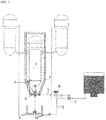
- FIG. 2 illustrates a detailed configuration and an operation of a passively operating ex-vessel corium cooling device which is mechanically driven by using tension of a string.
- a cooling system may be configured, which is passively operating so as to open the cooling water injection valve by mechanical driving force at the time when a fusible plug is damaged by the corium by mechanically connecting a fusible plug part of a reactor insulation and the cooling water injection valve supplied to the core catcher.
- the corium 2 released through a damaged portion of the nuclear pressure vessel 1 is primarily collected in an insulation body 3 installed outside the nuclear pressure vessel and finally collected in a fusible plug (4) part at a lowermost end of the insulation body by the gravity.
- the fusible plug (4) part is constituted by two layers and an upper layer is made of a sacrificial material which is large in reactivity with the corium and is easily eroded and damaged and a lower layer is configured to fixedly bury a string 6 which is a mediator that transfers a mechanical signal to the cooling water injection valve 7 when the fusible plug 4, made in a metallic material, is damaged.
- the cooling water injection valve which is kept to be closed by the tension of the string connecting both ends of the fusible plug 4 and the cooling water injection valve 7 is configured to be switched to be opened by the tension of the string 6 fixedly buried and installed in the fusible plug 4, when the corium drops, and finally the cooling water injection starts.
- a string tension controller 8 is installed between an end of the string 6 fixedly buried in the fusible plug 4 and a cooling water injection valve (7) driving device at the opposite end, and the tension of the string 6 which supports both ends is configured to be periodically checked and adjusted by the string tension controller 8.
- the string 6 is controlled not to be cut off in a situation in which no severe accident occurs to minimize a cooling water injection failure possibility.
- FIG. 3 illustrates an example of a layout of a string 6 fixed and buried in a fusible plug 4.
- the string is disposed and installed so as to maximally accommodate an area of the fusible plug 4 positioned at the lowermost end where the corium released to the insulation body is finally collected and installed in two series bidirectionally to ensure the redundancy on the supply of the cooling water.
- the string is installed in two series bidirectionally and two strings are connected and installed into one cooling water injection valve for each series and only when both of two installed strings are cut off, the cooling water injection valve is made to be opened, thereby minimizing a mechanical malfunction possibility in a normal state.
- two or more strings may be installed by considering reliability and the malfunction possibility.
- a basement 10 made of concrete is installed under the core catcher.
- the cooling is made while the cooling water passes a channel between the basement 10 and the core catcher.
- direct cooling is made while the cooling water flows into an upper portion of the core catcher and after the direct cooling, the cooing is made through natural circulation.
- a pipe 9 for transporting the cooling water in the cooling water tank to the core catcher having the corium is preferably connected and installed at a height corresponding to a lower end of the cooling water tank and the lower end of the core catcher so as to rapidly transport the cooling water by using water pressure.
- the present invention includes corium 2 released through a damaged portion of a reactor pressure vessel 1, a fusible plug 4 installed at a lowermost end of an insulation body 3 in which the corium is collected by gravity, and a string 6 buried and installed on a lower layer of the fusible plug 4 as a mediator so as to transfer a mechanical signal to a cooling water injection valve 7 when the fusible plug 4 made in a metallic material is damaged.
- the present invention includes a core catcher 5 installed immediately below the fusible plug so as to contain the corium while the corium drops by penetrating the fusible plug, a cooling water tank outside a reactor pressure vessel, and a pipe 9 connected and installed for transporting the cooling water in the cooling water tank to the core catcher 5 having the corium.
- the cooling water injection valve 7 is installed, which is installed at one side of the pipe and is interlocked with the string.
- the cooling water injection valve which is kept to be closed by the tension of the string connecting both ends of the fusible plug 4 and the cooling water injection valve 7 is configured to be switched to be opened by the tension of the string 6 fixedly buried and installed in the fusible plug 4 when the corium drops.
- the passively operating cooling device having a core catcher 3 provided at the lower part of a reactor pressure vessel 2 in a reactor cavity area so as to prepare for severe accidents damaging to the reactor pressure vessel, and injecting, by gravity, cooling water for cooling corium, by the water supply source of an in-containment refueling water storage tank 4 when a cooling water injection valve 5 is opened, wherein the cooling water injection valve is interlocked with a string so as to be opened according to a temperature, of which the value exceeds a set value, and is mechanically driven using the tension of a string so that industrial applicability is very high.
Landscapes
- Physics & Mathematics (AREA)
- Engineering & Computer Science (AREA)
- Plasma & Fusion (AREA)
- General Engineering & Computer Science (AREA)
- High Energy & Nuclear Physics (AREA)
- Structure Of Emergency Protection For Nuclear Reactors (AREA)
- Monitoring And Testing Of Nuclear Reactors (AREA)
Abstract
Description
- The present invention relates to a passively operating cooling device for ex-vessel corium, the passively operating cooling device having a
core catcher 3 provided below areactor pressure vessel 2 in a reactor cavity area so as to prepare for severe accidents damaging to the nuclear reactor pressure vessel, and injecting, by gravity, cooling water for cooling corium, by the water supply source of an in-containment refuelingwater storage tank 4 when a coolingwater injection valve 5 is opened, wherein the cooling water injection valve is interlocked with a string so as to be opened according to a temperature, of which the value exceeds a set value, and is mechanically driven using the tension of the string. - When a severe accident, which a core is melted, occurs in a reactor pressure vessel installed inside a containment building of a nuclear power plant, corium is released to a reactor cavity through a damaged part of a reactor pressure vessel. A facility that collects, holds, and cools the corium in a containment building cavity is called an ex-vessel corium cooling device (core catcher) in preparation for such a situation.
- In general, after the corium released from the reactor pressure vessel reaches the core catcher, cooling water is directly or indirectly supplied to remove decay heat of the corium and in this case, stable cooling water supplying is a required element for high-temperature corium.
- In the cooling water injection in the related art, used is a method in which when a signal exceeding a certain temperature is generated from a temperature measuring instrument installed at a specific point in a cavity around the core catcher by a motor driven valve (MOV) powered by a DC battery provided separately from an inside/outside power supply, a valve is opened to inject the cooling water.
- However, in such a core catcher cooling water injection method, there is a cooling water injection failure possibility due to an active device failure, lack of integrity of a temperature measuring instrument in a serious accident condition, and lowered reliability of the temperature signal.
- Korean Patent Laid-Open Publication No.
10-2014-0139947 10-2014-0051622 - An object to be solved by the present invention is contrived to solve the problem and is to provide a passively operating ex-vessel corium cooling device which is mechanically driven by the tension of a string without requiring power and measurement in cooling water injection of a core catcher.
- A solving means of the problem of the present invention is provide a passively operating cooling device for ex-vessel corium, which includes: corium released through a damaged part of a reactor pressure vessel; a fusible plug installed at a lowermost portion of an insulation in which the corium is collected by gravity; a string cut off when the fusible plug is damaged by a metallic material below the fusible plug and buried and installed so as to transfer a mechanical signal to a cooling water injection valve; a core catcher installed immediately below the fusible plug so as to contain the corium while the corium drops by penetrating the fusible plug; a cooling water tank outside a nuclear reactor in order to cool the corium; a pipe for transporting the cooling water in the cooling water tank to the core catcher having the corium; and a cooling water injection valve configured to be installed at one side of the pipe and interlocked with the string, in which the cooling water injection valve which is kept to be closed by tension of the string connecting both ends of the fusible plug and the cooling water injection valve is configured to be switched to be opened while the string fixedly buried and installed in the fusible plug when the corium drops.
- Another solving means of the problem of the present invention is to provide the passively operating cooling device for ex-vessel corium, in which a string tension controller is installed between an end of the string fixedly buried in the fusible plug and a cooling water injection valve driving device at the opposite end, and the tension of the string which supports both ends is configured to be periodically checked and adjusted by the string tension controller.
- Yet another solving means of the problem of the present invention is to provide the passively operating cooling device for ex-vessel corium, in which the string is disposed and installed so as to be maximally accommodated with an area of the fusible plug and installed bidirectionally in two series and two strings are installed in one cooling water injection valve for each series so as to minimize a mechanical malfunction possibility in a normal state, and the cooling water injection valve is opened only when all of two strings are cut off.
- Still yet another solving means of the problem of the present invention is to provide the passively operating cooling device for ex-vessel corium, in which the pipe for transporting the cooling water in the cooling water tank to the core catcher having the corium is fixedly installed at a height corresponding to a lower end of the cooling water tank and the lower end of the core catcher so as to rapidly transport the cooling water by water pressure.
- By a core catcher according to the present invention, since the core catcher is passively driven without a power supply and a measurement instrument in injecting cooling water, an operation failure possibility by power and measurement related elements is fundamentally excluded to minimize a possibility of stream explosion due to the flooding of cooling water before corium reaches and this corium cooling device can be easily inspected.
-
-
FIG. 1 is a cross-sectional configuration diagram schematically illustrating a core catcher system installed in the related art. -
FIG. 2 illustrates a detailed configuration and an operation of a passively operating ex-vessel corium cooling device which is mechanically driven by the tension of a string. -
FIG. 3 illustrates an example of a layout of a string fixed and buried in a fusible plug. - The present invention provides a passively operating cooling device for ex-vessel corium, which includes: corium released through a damaged part of a reactor pressure vessel; a fusible plug installed at a lowermost portion of an insulation in which the corium is collected by gravity; a string cut off when the fusible plug is damaged by a metallic material below the fusible plug and buried and installed so as to transfer a mechanical signal to a cooling water injection valve; a core catcher installed immediately below the fusible plug so as to contain the corium while the corium drops by penetrating the fusible plug; a cooling water tank outside a nuclear reactor in order to cool the corium; a pipe for transporting the cooling water in the cooling water tank to the core catcher having the corium; and a cooling water injection valve configured to be installed at one side of the pipe and interlocked with the string, in which the cooling water injection valve which is kept to be closed by tension of the string connecting both ends of the fusible plug and the cooling water injection valve is configured to be switched to be opened while the string fixedly buried and installed in the fusible plug at the time when the corium drops.
- Detailed contents for carrying out the present invention will be described.
- The present invention relates to a passively operating cooling device for ex-vessel corium, the passively operating cooling device having a core catcher provided below a reactor pressure vessel in a reactor cavity area so as to prepare for severe accidents damaging to the reactor pressure vessel, and injecting, by gravity, cooling water for cooling corium, by the water supply source of an in-containment refueling water storage tank when a cooling water injection valve is opened, wherein the cooling water injection valve is interlocked with a string so as to be opened according to a temperature, of which the value exceeds a set value, and is mechanically driven using the tension of the string. A detailed embodiment according to the present invention will be described.
- A detailed embodiment according to the present invention will be described based on drawings.
-
FIG. 1 is a cross-sectional configuration diagram schematically illustrating a core catcher system installed in the related art. There is a scheme in which acore catcher 3 is installed below areactor pressure vessel 2 so as to prepare for severe accidents damaging to a reactor pressure vessel, a water source of an in-containment refuelingwater storage tank 4 is used, and the water for cooling the corium is injected by gravity when the coolingwater injection valve 5 is opened and the valve is opened by a temperature which exceeds a set value by receiving a signal of atemperature measurement instrument 6 installed in a reactor cavity. -
FIG. 2 illustrates a detailed configuration and an operation of a passively operating ex-vessel corium cooling device which is mechanically driven by using tension of a string. A cooling system may be configured, which is passively operating so as to open the cooling water injection valve by mechanical driving force at the time when a fusible plug is damaged by the corium by mechanically connecting a fusible plug part of a reactor insulation and the cooling water injection valve supplied to the core catcher. Thecorium 2 released through a damaged portion of the nuclear pressure vessel 1 is primarily collected in aninsulation body 3 installed outside the nuclear pressure vessel and finally collected in a fusible plug (4) part at a lowermost end of the insulation body by the gravity. - The fusible plug (4) part is constituted by two layers and an upper layer is made of a sacrificial material which is large in reactivity with the corium and is easily eroded and damaged and a lower layer is configured to fixedly bury a
string 6 which is a mediator that transfers a mechanical signal to the coolingwater injection valve 7 when the fusible plug 4, made in a metallic material, is damaged. - When the erosion of the sacrificial material starts through a mutual reaction of a high-temperature corium and the sacrificial material of the fusible plug and the corium drops to the
core catcher 5 installed at a direct lower portion by penetrating the fusible plug part by continuous erosion, the cooling water injection valve which is kept to be closed by the tension of the string connecting both ends of thefusible plug 4 and the coolingwater injection valve 7 is configured to be switched to be opened by the tension of thestring 6 fixedly buried and installed in thefusible plug 4, when the corium drops, and finally the cooling water injection starts. - Further, a
string tension controller 8 is installed between an end of thestring 6 fixedly buried in thefusible plug 4 and a cooling water injection valve (7) driving device at the opposite end, and the tension of thestring 6 which supports both ends is configured to be periodically checked and adjusted by thestring tension controller 8. - The
string 6 is controlled not to be cut off in a situation in which no severe accident occurs to minimize a cooling water injection failure possibility. -
FIG. 3 illustrates an example of a layout of astring 6 fixed and buried in afusible plug 4. - The string is disposed and installed so as to maximally accommodate an area of the
fusible plug 4 positioned at the lowermost end where the corium released to the insulation body is finally collected and installed in two series bidirectionally to ensure the redundancy on the supply of the cooling water. - Further, the string is installed in two series bidirectionally and two strings are connected and installed into one cooling water injection valve for each series and only when both of two installed strings are cut off, the cooling water injection valve is made to be opened, thereby minimizing a mechanical malfunction possibility in a normal state. Of course, two or more strings may be installed by considering reliability and the malfunction possibility.
- A
basement 10 made of concrete is installed under the core catcher. When the cooling water first flows in, the cooling is made while the cooling water passes a channel between thebasement 10 and the core catcher. - After a predetermined time, direct cooling is made while the cooling water flows into an upper portion of the core catcher and after the direct cooling, the cooing is made through natural circulation.
- A
pipe 9 for transporting the cooling water in the cooling water tank to the core catcher having the corium is preferably connected and installed at a height corresponding to a lower end of the cooling water tank and the lower end of the core catcher so as to rapidly transport the cooling water by using water pressure. - The technical configuration of the passively operating cooling device for ex-vessel corium described above is summarized as below.
- The present invention includes
corium 2 released through a damaged portion of a reactor pressure vessel 1, afusible plug 4 installed at a lowermost end of aninsulation body 3 in which the corium is collected by gravity, and astring 6 buried and installed on a lower layer of thefusible plug 4 as a mediator so as to transfer a mechanical signal to a coolingwater injection valve 7 when thefusible plug 4 made in a metallic material is damaged. - Further, the present invention includes a
core catcher 5 installed immediately below the fusible plug so as to contain the corium while the corium drops by penetrating the fusible plug, a cooling water tank outside a reactor pressure vessel, and apipe 9 connected and installed for transporting the cooling water in the cooling water tank to thecore catcher 5 having the corium. - The cooling
water injection valve 7 is installed, which is installed at one side of the pipe and is interlocked with the string. - The cooling water injection valve which is kept to be closed by the tension of the string connecting both ends of the
fusible plug 4 and the coolingwater injection valve 7 is configured to be switched to be opened by the tension of thestring 6 fixedly buried and installed in thefusible plug 4 when the corium drops. - In the present invention, since easy cooling can be made by providing a passively operating cooling device for ex-vessel corium, the passively operating cooling device having a
core catcher 3 provided at the lower part of areactor pressure vessel 2 in a reactor cavity area so as to prepare for severe accidents damaging to the reactor pressure vessel, and injecting, by gravity, cooling water for cooling corium, by the water supply source of an in-containment refuelingwater storage tank 4 when a coolingwater injection valve 5 is opened, wherein the cooling water injection valve is interlocked with a string so as to be opened according to a temperature, of which the value exceeds a set value, and is mechanically driven using the tension of a string so that industrial applicability is very high.
Claims (4)
- A passively operating cooling device for ex-vessel corium, comprising:corium 2 released through a damaged part of a nuclear pressure vessel 1;a fusible plug 4 installed at a lowermost portion of an insulation 3 in which the corium is collected by gravity;a string 6 cut off when the fusible plug 4 is damaged by a metallic material under the fusible plug 4 and buried and installed so as to transfer a mechanical signal to a cooling water injection valve 7;a core catcher 5 installed immediately below the fusible plug so as to contain the corium while the corium drops by penetrating the fusible plug;a cooling water tank outside a nuclear reactor in order to cool the corium;a pipe for transporting the cooling water in the cooling water tank to the core catcher 5 having the corium; anda cooling water injection valve 7 configured to be installed at one side of the pipe and interlocked with the string,wherein the cooling water injection valve which is kept to be closed by tension of the string connecting both ends of the fusible plug 4 and the cooling water injection valve 7 is configured to be switched to be opened while the string 6 fixedly buried and installed in the fusible plug 4 is cut when the corium drops.
- The passively operating cooling device for ex-vessel corium of claim 1, wherein a string tension controller 8 is installed between an end of the string fixedly buried in the fusible plug and a cooling water injection valve driving device at the opposite end, and
the tension of the string 6 which supports both ends is configured to be periodically checked and adjusted by the string tension controller 8. - The passively operating cooling device for ex-vessel corium of claim 2, wherein the string is disposed and installed so as to be maximally accommodated with an area of the fusible plug and installed bidirectionally in two series and the cooling water injection valve is configured to be opened only when all of two strings are cut off in one cooling water injection valve even for each series so as to minimize a mechanical malfunction possibility in a normal state.
- The passively operating cooling device for ex-vessel corium of claim 2, wherein the pipe 9 for transporting the cooling water in the cooling water tank to the core catcher having the corium is fixedly installed at a height corresponding to a lower end of the cooling water tank and the lower end of the core catcher so as to rapidly transport the cooling water by using water pressure.
Priority Applications (1)
| Application Number | Priority Date | Filing Date | Title |
|---|---|---|---|
| PL15890804T PL3291242T3 (en) | 2015-04-27 | 2015-05-13 | Passively operating cooling device for ex-vessel corium |
Applications Claiming Priority (2)
| Application Number | Priority Date | Filing Date | Title |
|---|---|---|---|
| KR1020150058933A KR101665248B1 (en) | 2015-04-27 | 2015-04-27 | Passive Actuator for Ex-vessel Corium Cooling System |
| PCT/KR2015/004751 WO2016175363A1 (en) | 2015-04-27 | 2015-05-13 | Passively operating cooling device for ex-vessel corium |
Publications (3)
| Publication Number | Publication Date |
|---|---|
| EP3291242A1 true EP3291242A1 (en) | 2018-03-07 |
| EP3291242A4 EP3291242A4 (en) | 2018-12-26 |
| EP3291242B1 EP3291242B1 (en) | 2019-12-18 |
Family
ID=57173347
Family Applications (1)
| Application Number | Title | Priority Date | Filing Date |
|---|---|---|---|
| EP15890804.6A Active EP3291242B1 (en) | 2015-04-27 | 2015-05-13 | Passively operating cooling device for ex-vessel corium |
Country Status (5)
| Country | Link |
|---|---|
| EP (1) | EP3291242B1 (en) |
| KR (1) | KR101665248B1 (en) |
| CN (1) | CN107873102B (en) |
| PL (1) | PL3291242T3 (en) |
| WO (1) | WO2016175363A1 (en) |
Cited By (1)
| Publication number | Priority date | Publication date | Assignee | Title |
|---|---|---|---|---|
| EP3336852A4 (en) * | 2015-08-11 | 2019-03-27 | Korea Hydro & Nuclear Power Co., Ltd | Nuclear reactor insulator having molten core collecting function |
Families Citing this family (7)
| Publication number | Priority date | Publication date | Assignee | Title |
|---|---|---|---|---|
| KR101988265B1 (en) * | 2017-05-24 | 2019-06-12 | 한국원자력연구원 | Cooling Facility in a Reactor Vessel and Electric Power Generation System |
| CN108053895B (en) * | 2017-11-06 | 2021-06-25 | 中国核电工程有限公司 | A reactor core melt capture device with sub-package enhanced cooling |
| CN109346197B (en) * | 2018-11-13 | 2020-01-31 | 中国核动力研究设计院 | double-barrier melt containment protection system |
| CN111810707B (en) * | 2020-08-26 | 2021-09-03 | 中国原子能科学研究院 | Valve gate |
| KR102512170B1 (en) | 2020-12-15 | 2023-03-20 | 한국수력원자력 주식회사 | Core catcher apparatus having improved safety in supply of coolant |
| KR102514705B1 (en) | 2020-12-29 | 2023-03-27 | 한국수력원자력 주식회사 | Core catcher apparatus having improved operation safety |
| CN113450933B (en) * | 2021-08-19 | 2024-05-14 | 中国原子能科学研究院 | Reactor waste heat discharging system and method |
Family Cites Families (14)
| Publication number | Priority date | Publication date | Assignee | Title |
|---|---|---|---|---|
| JPH0762717B2 (en) * | 1988-09-21 | 1995-07-05 | 株式会社日立製作所 | Liquid injection device for high temperature and high pressure vessels |
| RU2063071C1 (en) * | 1994-05-30 | 1996-06-27 | Опытное Конструкторское Бюро "Гидропресс" | Emergency core-disruptive cooling system for nuclear power reactor |
| KR100549862B1 (en) * | 2004-02-10 | 2006-02-08 | 한국원자력연구소 | Core melt cooling device through reactor vessel and method |
| KR100873647B1 (en) * | 2007-06-29 | 2008-12-12 | 한국원자력연구원 | Out-of-furnace steam explosion prevention device and method |
| JP4987681B2 (en) * | 2007-12-12 | 2012-07-25 | 株式会社東芝 | Primary containment vessel and leak detection floor |
| JP5235614B2 (en) * | 2008-11-05 | 2013-07-10 | 日立Geニュークリア・エナジー株式会社 | Nuclear power plant and control method |
| KR101106456B1 (en) * | 2010-04-16 | 2012-01-20 | 국립대학법인 울산과학기술대학교 산학협력단 | Method for using graphene / graphene-oxide dispersion coolant and reactor core melt cooling system using the same |
| KR101233314B1 (en) * | 2011-09-20 | 2013-02-14 | 한국수력원자력 주식회사 | Passive multiple cooling device for the molten corium of a reactor vessel |
| KR101389276B1 (en) * | 2012-07-13 | 2014-04-25 | 한국원자력연구원 | Passive Safety System of Integral Reactor |
| EP2747087A1 (en) * | 2012-12-22 | 2014-06-25 | AREVA GmbH | Pipe shut-off device and apparatus for the emergency supply of cooling fluid to the fuel rods arranged in the reactor vessel of an nuclear power station with such a pipe shut-off device |
| US11373768B2 (en) * | 2013-03-12 | 2022-06-28 | Bwxt Mpower, Inc. | Refueling water storage tank (RWST) with tailored passive emergency core cooling (ECC) flow |
| KR101504217B1 (en) * | 2013-05-28 | 2015-03-20 | 한국원자력연구원 | Passive and sequential cooling device of the core melt and nuclear power plant with the device |
| US20140376680A1 (en) * | 2013-06-25 | 2014-12-25 | Areva Inc. | Containment Sump Ceramic Drain Plug |
| KR101445494B1 (en) * | 2013-07-18 | 2014-09-26 | 한국원자력연구원 | Passive residual heat removal system of reserch reactor using gravity core cooling tank |
-
2015
- 2015-04-27 KR KR1020150058933A patent/KR101665248B1/en active Active
- 2015-05-13 EP EP15890804.6A patent/EP3291242B1/en active Active
- 2015-05-13 WO PCT/KR2015/004751 patent/WO2016175363A1/en not_active Ceased
- 2015-05-13 CN CN201580079333.0A patent/CN107873102B/en active Active
- 2015-05-13 PL PL15890804T patent/PL3291242T3/en unknown
Cited By (1)
| Publication number | Priority date | Publication date | Assignee | Title |
|---|---|---|---|---|
| EP3336852A4 (en) * | 2015-08-11 | 2019-03-27 | Korea Hydro & Nuclear Power Co., Ltd | Nuclear reactor insulator having molten core collecting function |
Also Published As
| Publication number | Publication date |
|---|---|
| EP3291242B1 (en) | 2019-12-18 |
| PL3291242T3 (en) | 2020-04-30 |
| EP3291242A4 (en) | 2018-12-26 |
| CN107873102B (en) | 2020-03-27 |
| CN107873102A (en) | 2018-04-03 |
| KR101665248B1 (en) | 2016-10-12 |
| WO2016175363A1 (en) | 2016-11-03 |
Similar Documents
| Publication | Publication Date | Title |
|---|---|---|
| EP3291242B1 (en) | Passively operating cooling device for ex-vessel corium | |
| KR101389276B1 (en) | Passive Safety System of Integral Reactor | |
| CN101939793B (en) | a nuclear reactor | |
| CN202102728U (en) | Safety system used for guaranteeing safety of nuclear power plant | |
| KR101434532B1 (en) | Passive Safety Injection System using Safety Injection Tank | |
| CN203366760U (en) | Reactor cavity water-injection system of nuclear power station | |
| CN201570286U (en) | A reactor cavity water injection system for nuclear power system | |
| CN102881340A (en) | Emergency shut-down system and method combining activeness and passiveness | |
| WO2013184207A2 (en) | Emergency and back-up cooling of nuclear fuel and reactors | |
| CN205751540U (en) | Major accident mitigation system of nuclear | |
| US9911514B2 (en) | Nuclear reactor cavity floor passive heat removal system | |
| KR101463441B1 (en) | High concentration boron injection system and safety injection system having the same | |
| Chun et al. | Safety evaluation of small-break LOCA with various locations and sizes for SMART adopting fully passive safety system using MARS code | |
| CN204303360U (en) | The non-active Reactor cavity flooding system of nuclear power station | |
| CN107845434B (en) | Reactor core auxiliary cooling system of passive reactor | |
| CN106651217B (en) | Core flooding evaluation method for nuclear power plant equipped with core catcher | |
| CN103426484A (en) | Method used for preventing pressure vessels from melting damages caused by molten materials in reactors, and system used for method | |
| CN209625811U (en) | A kind of safety injection system and nuclear power station | |
| KR100873647B1 (en) | Out-of-furnace steam explosion prevention device and method | |
| CN204407021U (en) | Nuclear power station non-active spentnuclear fuel pond emergence compensating water system | |
| CN110610770A (en) | A pressurized water reactor nuclear power plant safety injection box automatic isolation system and method | |
| CN104751907A (en) | Passive water replenishment system for spent fuel pool in nuclear power plant | |
| KR102557539B1 (en) | Direct cooling water filling system of nuclear reactor containment building | |
| CN114038588A (en) | Severe accident handling system and method for nuclear power station and nuclear power station | |
| CN114068046A (en) | Reactor and safety method for reactor for core melting event |
Legal Events
| Date | Code | Title | Description |
|---|---|---|---|
| STAA | Information on the status of an ep patent application or granted ep patent |
Free format text: STATUS: THE INTERNATIONAL PUBLICATION HAS BEEN MADE |
|
| PUAI | Public reference made under article 153(3) epc to a published international application that has entered the european phase |
Free format text: ORIGINAL CODE: 0009012 |
|
| STAA | Information on the status of an ep patent application or granted ep patent |
Free format text: STATUS: REQUEST FOR EXAMINATION WAS MADE |
|
| 17P | Request for examination filed |
Effective date: 20171025 |
|
| AK | Designated contracting states |
Kind code of ref document: A1 Designated state(s): AL AT BE BG CH CY CZ DE DK EE ES FI FR GB GR HR HU IE IS IT LI LT LU LV MC MK MT NL NO PL PT RO RS SE SI SK SM TR |
|
| AX | Request for extension of the european patent |
Extension state: BA ME |
|
| RIN1 | Information on inventor provided before grant (corrected) |
Inventor name: LEE, GEUN SUNG Inventor name: KIM, YONG SU Inventor name: KIM, GEE HYAN Inventor name: HWANG, DO HYEON |
|
| DAV | Request for validation of the european patent (deleted) | ||
| DAX | Request for extension of the european patent (deleted) | ||
| A4 | Supplementary search report drawn up and despatched |
Effective date: 20181127 |
|
| RIC1 | Information provided on ipc code assigned before grant |
Ipc: G21C 15/18 20060101AFI20181119BHEP Ipc: G21C 9/016 20060101ALI20181119BHEP |
|
| GRAP | Despatch of communication of intention to grant a patent |
Free format text: ORIGINAL CODE: EPIDOSNIGR1 |
|
| STAA | Information on the status of an ep patent application or granted ep patent |
Free format text: STATUS: GRANT OF PATENT IS INTENDED |
|
| INTG | Intention to grant announced |
Effective date: 20190802 |
|
| GRAS | Grant fee paid |
Free format text: ORIGINAL CODE: EPIDOSNIGR3 |
|
| GRAA | (expected) grant |
Free format text: ORIGINAL CODE: 0009210 |
|
| STAA | Information on the status of an ep patent application or granted ep patent |
Free format text: STATUS: THE PATENT HAS BEEN GRANTED |
|
| AK | Designated contracting states |
Kind code of ref document: B1 Designated state(s): AL AT BE BG CH CY CZ DE DK EE ES FI FR GB GR HR HU IE IS IT LI LT LU LV MC MK MT NL NO PL PT RO RS SE SI SK SM TR |
|
| REG | Reference to a national code |
Ref country code: CH Ref legal event code: EP |
|
| REG | Reference to a national code |
Ref country code: IE Ref legal event code: FG4D |
|
| REG | Reference to a national code |
Ref country code: DE Ref legal event code: R096 Ref document number: 602015044097 Country of ref document: DE |
|
| REG | Reference to a national code |
Ref country code: AT Ref legal event code: REF Ref document number: 1215490 Country of ref document: AT Kind code of ref document: T Effective date: 20200115 |
|
| REG | Reference to a national code |
Ref country code: FI Ref legal event code: FGE |
|
| REG | Reference to a national code |
Ref country code: NL Ref legal event code: MP Effective date: 20191218 |
|
| PG25 | Lapsed in a contracting state [announced via postgrant information from national office to epo] |
Ref country code: BG Free format text: LAPSE BECAUSE OF FAILURE TO SUBMIT A TRANSLATION OF THE DESCRIPTION OR TO PAY THE FEE WITHIN THE PRESCRIBED TIME-LIMIT Effective date: 20200318 Ref country code: LT Free format text: LAPSE BECAUSE OF FAILURE TO SUBMIT A TRANSLATION OF THE DESCRIPTION OR TO PAY THE FEE WITHIN THE PRESCRIBED TIME-LIMIT Effective date: 20191218 Ref country code: GR Free format text: LAPSE BECAUSE OF FAILURE TO SUBMIT A TRANSLATION OF THE DESCRIPTION OR TO PAY THE FEE WITHIN THE PRESCRIBED TIME-LIMIT Effective date: 20200319 Ref country code: NO Free format text: LAPSE BECAUSE OF FAILURE TO SUBMIT A TRANSLATION OF THE DESCRIPTION OR TO PAY THE FEE WITHIN THE PRESCRIBED TIME-LIMIT Effective date: 20200318 Ref country code: SE Free format text: LAPSE BECAUSE OF FAILURE TO SUBMIT A TRANSLATION OF THE DESCRIPTION OR TO PAY THE FEE WITHIN THE PRESCRIBED TIME-LIMIT Effective date: 20191218 Ref country code: LV Free format text: LAPSE BECAUSE OF FAILURE TO SUBMIT A TRANSLATION OF THE DESCRIPTION OR TO PAY THE FEE WITHIN THE PRESCRIBED TIME-LIMIT Effective date: 20191218 |
|
| REG | Reference to a national code |
Ref country code: LT Ref legal event code: MG4D |
|
| PG25 | Lapsed in a contracting state [announced via postgrant information from national office to epo] |
Ref country code: HR Free format text: LAPSE BECAUSE OF FAILURE TO SUBMIT A TRANSLATION OF THE DESCRIPTION OR TO PAY THE FEE WITHIN THE PRESCRIBED TIME-LIMIT Effective date: 20191218 Ref country code: RS Free format text: LAPSE BECAUSE OF FAILURE TO SUBMIT A TRANSLATION OF THE DESCRIPTION OR TO PAY THE FEE WITHIN THE PRESCRIBED TIME-LIMIT Effective date: 20191218 |
|
| PG25 | Lapsed in a contracting state [announced via postgrant information from national office to epo] |
Ref country code: AL Free format text: LAPSE BECAUSE OF FAILURE TO SUBMIT A TRANSLATION OF THE DESCRIPTION OR TO PAY THE FEE WITHIN THE PRESCRIBED TIME-LIMIT Effective date: 20191218 |
|
| PG25 | Lapsed in a contracting state [announced via postgrant information from national office to epo] |
Ref country code: EE Free format text: LAPSE BECAUSE OF FAILURE TO SUBMIT A TRANSLATION OF THE DESCRIPTION OR TO PAY THE FEE WITHIN THE PRESCRIBED TIME-LIMIT Effective date: 20191218 Ref country code: NL Free format text: LAPSE BECAUSE OF FAILURE TO SUBMIT A TRANSLATION OF THE DESCRIPTION OR TO PAY THE FEE WITHIN THE PRESCRIBED TIME-LIMIT Effective date: 20191218 Ref country code: RO Free format text: LAPSE BECAUSE OF FAILURE TO SUBMIT A TRANSLATION OF THE DESCRIPTION OR TO PAY THE FEE WITHIN THE PRESCRIBED TIME-LIMIT Effective date: 20191218 Ref country code: PT Free format text: LAPSE BECAUSE OF FAILURE TO SUBMIT A TRANSLATION OF THE DESCRIPTION OR TO PAY THE FEE WITHIN THE PRESCRIBED TIME-LIMIT Effective date: 20200513 |
|
| PG25 | Lapsed in a contracting state [announced via postgrant information from national office to epo] |
Ref country code: SM Free format text: LAPSE BECAUSE OF FAILURE TO SUBMIT A TRANSLATION OF THE DESCRIPTION OR TO PAY THE FEE WITHIN THE PRESCRIBED TIME-LIMIT Effective date: 20191218 Ref country code: SK Free format text: LAPSE BECAUSE OF FAILURE TO SUBMIT A TRANSLATION OF THE DESCRIPTION OR TO PAY THE FEE WITHIN THE PRESCRIBED TIME-LIMIT Effective date: 20191218 Ref country code: IS Free format text: LAPSE BECAUSE OF FAILURE TO SUBMIT A TRANSLATION OF THE DESCRIPTION OR TO PAY THE FEE WITHIN THE PRESCRIBED TIME-LIMIT Effective date: 20200418 |
|
| REG | Reference to a national code |
Ref country code: DE Ref legal event code: R097 Ref document number: 602015044097 Country of ref document: DE |
|
| REG | Reference to a national code |
Ref country code: AT Ref legal event code: MK05 Ref document number: 1215490 Country of ref document: AT Kind code of ref document: T Effective date: 20191218 |
|
| PLBE | No opposition filed within time limit |
Free format text: ORIGINAL CODE: 0009261 |
|
| STAA | Information on the status of an ep patent application or granted ep patent |
Free format text: STATUS: NO OPPOSITION FILED WITHIN TIME LIMIT |
|
| PG25 | Lapsed in a contracting state [announced via postgrant information from national office to epo] |
Ref country code: DK Free format text: LAPSE BECAUSE OF FAILURE TO SUBMIT A TRANSLATION OF THE DESCRIPTION OR TO PAY THE FEE WITHIN THE PRESCRIBED TIME-LIMIT Effective date: 20191218 Ref country code: ES Free format text: LAPSE BECAUSE OF FAILURE TO SUBMIT A TRANSLATION OF THE DESCRIPTION OR TO PAY THE FEE WITHIN THE PRESCRIBED TIME-LIMIT Effective date: 20191218 |
|
| 26N | No opposition filed |
Effective date: 20200921 |
|
| PG25 | Lapsed in a contracting state [announced via postgrant information from national office to epo] |
Ref country code: SI Free format text: LAPSE BECAUSE OF FAILURE TO SUBMIT A TRANSLATION OF THE DESCRIPTION OR TO PAY THE FEE WITHIN THE PRESCRIBED TIME-LIMIT Effective date: 20191218 Ref country code: AT Free format text: LAPSE BECAUSE OF FAILURE TO SUBMIT A TRANSLATION OF THE DESCRIPTION OR TO PAY THE FEE WITHIN THE PRESCRIBED TIME-LIMIT Effective date: 20191218 |
|
| REG | Reference to a national code |
Ref country code: DE Ref legal event code: R119 Ref document number: 602015044097 Country of ref document: DE |
|
| PG25 | Lapsed in a contracting state [announced via postgrant information from national office to epo] |
Ref country code: CH Free format text: LAPSE BECAUSE OF NON-PAYMENT OF DUE FEES Effective date: 20200531 Ref country code: IT Free format text: LAPSE BECAUSE OF FAILURE TO SUBMIT A TRANSLATION OF THE DESCRIPTION OR TO PAY THE FEE WITHIN THE PRESCRIBED TIME-LIMIT Effective date: 20191218 Ref country code: LI Free format text: LAPSE BECAUSE OF NON-PAYMENT OF DUE FEES Effective date: 20200531 Ref country code: MC Free format text: LAPSE BECAUSE OF FAILURE TO SUBMIT A TRANSLATION OF THE DESCRIPTION OR TO PAY THE FEE WITHIN THE PRESCRIBED TIME-LIMIT Effective date: 20191218 |
|
| REG | Reference to a national code |
Ref country code: BE Ref legal event code: MM Effective date: 20200531 |
|
| PG25 | Lapsed in a contracting state [announced via postgrant information from national office to epo] |
Ref country code: LU Free format text: LAPSE BECAUSE OF NON-PAYMENT OF DUE FEES Effective date: 20200513 |
|
| PG25 | Lapsed in a contracting state [announced via postgrant information from national office to epo] |
Ref country code: IE Free format text: LAPSE BECAUSE OF NON-PAYMENT OF DUE FEES Effective date: 20200513 |
|
| PG25 | Lapsed in a contracting state [announced via postgrant information from national office to epo] |
Ref country code: BE Free format text: LAPSE BECAUSE OF NON-PAYMENT OF DUE FEES Effective date: 20200531 Ref country code: DE Free format text: LAPSE BECAUSE OF NON-PAYMENT OF DUE FEES Effective date: 20201201 |
|
| PG25 | Lapsed in a contracting state [announced via postgrant information from national office to epo] |
Ref country code: TR Free format text: LAPSE BECAUSE OF FAILURE TO SUBMIT A TRANSLATION OF THE DESCRIPTION OR TO PAY THE FEE WITHIN THE PRESCRIBED TIME-LIMIT Effective date: 20191218 Ref country code: MT Free format text: LAPSE BECAUSE OF FAILURE TO SUBMIT A TRANSLATION OF THE DESCRIPTION OR TO PAY THE FEE WITHIN THE PRESCRIBED TIME-LIMIT Effective date: 20191218 Ref country code: CY Free format text: LAPSE BECAUSE OF FAILURE TO SUBMIT A TRANSLATION OF THE DESCRIPTION OR TO PAY THE FEE WITHIN THE PRESCRIBED TIME-LIMIT Effective date: 20191218 |
|
| PG25 | Lapsed in a contracting state [announced via postgrant information from national office to epo] |
Ref country code: MK Free format text: LAPSE BECAUSE OF FAILURE TO SUBMIT A TRANSLATION OF THE DESCRIPTION OR TO PAY THE FEE WITHIN THE PRESCRIBED TIME-LIMIT Effective date: 20191218 |
|
| PGFP | Annual fee paid to national office [announced via postgrant information from national office to epo] |
Ref country code: FI Payment date: 20250513 Year of fee payment: 11 |
|
| PGFP | Annual fee paid to national office [announced via postgrant information from national office to epo] |
Ref country code: PL Payment date: 20250506 Year of fee payment: 11 |
|
| PGFP | Annual fee paid to national office [announced via postgrant information from national office to epo] |
Ref country code: GB Payment date: 20250501 Year of fee payment: 11 |
|
| PGFP | Annual fee paid to national office [announced via postgrant information from national office to epo] |
Ref country code: FR Payment date: 20250508 Year of fee payment: 11 |
|
| PGFP | Annual fee paid to national office [announced via postgrant information from national office to epo] |
Ref country code: CZ Payment date: 20250430 Year of fee payment: 11 |