EP3291059A1 - Display system operable in a non-contact manner - Google Patents
Display system operable in a non-contact manner Download PDFInfo
- Publication number
- EP3291059A1 EP3291059A1 EP17187883.8A EP17187883A EP3291059A1 EP 3291059 A1 EP3291059 A1 EP 3291059A1 EP 17187883 A EP17187883 A EP 17187883A EP 3291059 A1 EP3291059 A1 EP 3291059A1
- Authority
- EP
- European Patent Office
- Prior art keywords
- user
- display
- wearable devices
- wireless communication
- communication module
- Prior art date
- Legal status (The legal status is an assumption and is not a legal conclusion. Google has not performed a legal analysis and makes no representation as to the accuracy of the status listed.)
- Withdrawn
Links
Images



Classifications
-
- G—PHYSICS
- G06—COMPUTING OR CALCULATING; COUNTING
- G06F—ELECTRIC DIGITAL DATA PROCESSING
- G06F3/00—Input arrangements for transferring data to be processed into a form capable of being handled by the computer; Output arrangements for transferring data from processing unit to output unit, e.g. interface arrangements
- G06F3/01—Input arrangements or combined input and output arrangements for interaction between user and computer
- G06F3/017—Gesture based interaction, e.g. based on a set of recognized hand gestures
-
- G—PHYSICS
- G06—COMPUTING OR CALCULATING; COUNTING
- G06F—ELECTRIC DIGITAL DATA PROCESSING
- G06F3/00—Input arrangements for transferring data to be processed into a form capable of being handled by the computer; Output arrangements for transferring data from processing unit to output unit, e.g. interface arrangements
- G06F3/01—Input arrangements or combined input and output arrangements for interaction between user and computer
- G06F3/011—Arrangements for interaction with the human body, e.g. for user immersion in virtual reality
- G06F3/014—Hand-worn input/output arrangements, e.g. data gloves
-
- G—PHYSICS
- G06—COMPUTING OR CALCULATING; COUNTING
- G06F—ELECTRIC DIGITAL DATA PROCESSING
- G06F3/00—Input arrangements for transferring data to be processed into a form capable of being handled by the computer; Output arrangements for transferring data from processing unit to output unit, e.g. interface arrangements
- G06F3/01—Input arrangements or combined input and output arrangements for interaction between user and computer
- G06F3/011—Arrangements for interaction with the human body, e.g. for user immersion in virtual reality
-
- G—PHYSICS
- G06—COMPUTING OR CALCULATING; COUNTING
- G06F—ELECTRIC DIGITAL DATA PROCESSING
- G06F3/00—Input arrangements for transferring data to be processed into a form capable of being handled by the computer; Output arrangements for transferring data from processing unit to output unit, e.g. interface arrangements
- G06F3/01—Input arrangements or combined input and output arrangements for interaction between user and computer
- G06F3/03—Arrangements for converting the position or the displacement of a member into a coded form
- G06F3/033—Pointing devices displaced or positioned by the user, e.g. mice, trackballs, pens or joysticks; Accessories therefor
- G06F3/0346—Pointing devices displaced or positioned by the user, e.g. mice, trackballs, pens or joysticks; Accessories therefor with detection of the device orientation or free movement in a three-dimensional [3D] space, e.g. 3D mice, 6-DOF [six degrees of freedom] pointers using gyroscopes, accelerometers or tilt-sensors
-
- G—PHYSICS
- G06—COMPUTING OR CALCULATING; COUNTING
- G06F—ELECTRIC DIGITAL DATA PROCESSING
- G06F3/00—Input arrangements for transferring data to be processed into a form capable of being handled by the computer; Output arrangements for transferring data from processing unit to output unit, e.g. interface arrangements
- G06F3/01—Input arrangements or combined input and output arrangements for interaction between user and computer
- G06F3/048—Interaction techniques based on graphical user interfaces [GUI]
- G06F3/0481—Interaction techniques based on graphical user interfaces [GUI] based on specific properties of the displayed interaction object or a metaphor-based environment, e.g. interaction with desktop elements like windows or icons, or assisted by a cursor's changing behaviour or appearance
- G06F3/0482—Interaction with lists of selectable items, e.g. menus
Definitions
- Embodiments described herein relate generally to a display system operable in a non-contact manner.
- a pointer disposed on a screen of a personal computer (PC) or the like is moved corresponding to the recognized motion, and an operation corresponding to a position of the pointer can be performed.
- a display system operable in a non-contact manner, comprising: a display; a wireless communication module; a plurality of user-wearable devices, each of which is attachable to or around a user's hand, associated with a unique identifier, and is configured to detect a hand gesture made by the user's hand and wirelessly transmit data corresponding to the detected hand gesture to the wireless communication module along with the unique identifier; and a control device configured to: activate operation of the display by one of the user-wearable devices, upon the wireless communication module receiving data of a first predetermined hand gesture from said one of the user-wearable devices; control the display to display a display element unique to said one of the user-wearable devices, upon activation of the operation thereby; and change display contents of the display while the operation is activated, based on data of a second predetermined hand gesture transmitted from said one of the user-wearable devices and received by the wireless communication module.
- the display element includes a background screen.
- a color of the background screen is unique to said one of the user-wearable devices.
- the display element includes a pointer.
- At least one of a color and a shape of the pointer is unique to said one of the user-wearable devices.
- the display element includes a display area indicating user attribute information.
- control device activates the operation by said one of the user-wearable devices, when operation by no other user-wearable devices are activated.
- control device is further configured to deactivate the operation of the display by said one of the user-wearable devices, upon the wireless communication module receiving data of a third predetermined hand gesture along with the unique identifier from said one of the user-wearable devices.
- the present invention further relates to a display system operable in a non-contact manner, comprising: a display; a wireless communication module; an image capturing device; and a control device configured to: biometrically authenticate a user through an image of the user captured by the image capturing device; activate operation of the display by the user, upon the image capturing device capturing an image of a first predetermined gesture made by the user; control the display to display a display element unique to the user, upon activation of the operation by the user; and change display contents of the display while the operation is activated, upon the image capturing device capturing an image of a second predetermined gesture made by the user.
- the display element includes a background screen.
- a color of the background screen is unique to the user.
- the display element includes a pointer.
- At least one of a color and a shape of the pointer is unique to the user.
- the display element includes a display area indicating user attribute information.
- control device activates the operation by the user, when operation by no other users is activated.
- control device is further configured to deactivate the operation of the display by the user, upon the image capturing device capturing an image of a third predetermined gesture made by the user.
- the present invention further relates to a method for operating a display device in a non-contact manner, comprising: detecting, by a user-wearable device attached to or around a user's hand, a first predetermined hand gesture made by the user's hand; wirelessly transmitting data corresponding to the first predetermined hand gesture along with a unique identifier of the user-wearable device, from the user-wearable device to a wireless communication module coupled to a display device; activating operation of the display by the user-wearable device, upon the wireless communication module receiving the data of the first predetermined hand gesture along with the unique identifier; controlling the display device to display a display element unique to the user-wearable device, upon activation of the operation thereby; and changing display contents of the display device based on data of a second predetermined hand gesture that is wirelessly transmitted along with the unique identifier from the user-wearable device and received by the wireless communication module.
- the operation by the user-wearable device is activated when no user-wearable device is activated.
- the method may further comprise: deactivating the operation of the display by the user-wearable device, upon the wireless communication module receiving data of a third predetermined hand gesture along with the unique identifier from the user-wearable device.
- the method may further comprise: while the operation by the user-wearable device is activated, prevent activating operation of the display by other user-wearable devices, even upon the wireless communication module receiving data of the first predetermined hand gesture from said other user-wearable devices.
- An exemplary embodiment provides a non-contact operation input device capable of easily distinguishing that which user's operation is reflected on a screen.
- a display system operable in a non-contact manner includes a display, a wireless communication module, a plurality of user-wearable devices, and a control device.
- Each of the user-wearable devices is attachable to or around a user's hand, associated with a unique identifier, and is configured to detect a hand gesture made by the user's hand and wirelessly transmit data corresponding to the detected hand gesture to the wireless communication module along with the unique identifier.
- the control device is configured to activate operation of the display by one of the user-wearable devices, upon the wireless communication module receiving data of a first predetermined hand gesture from said one of the user-wearable devices, control the display to display a display element unique to said one of the user-wearable devices, upon activation of the operation thereby, and change display contents of the display while the operation is activated, based on data of a second predetermined hand gesture transmitted from said one of the user-wearable devices and received by the wireless communication module.
- an operation input device and a program according to an exemplary embodiment of the present disclosure will be described in detail with reference to the drawings.
- an embodiment of the present disclosure is applied to a kitchen display for displaying order contents that is used in a store such as restaurants, but embodiments of the present disclosure is not limited to the embodiment.
- FIG. 1 illustrates a configuration of an operation input device 1 according to an embodiment.
- the operation input device 1 includes a display unit 11, a controller 12, a communication unit 13, and a motion recognition unit 14.
- the controller 12, the communication unit 13, and the motion recognition unit 14 may be integrated with the display unit 11 or may be configured as separate units.
- the display unit 11 includes a display device such as a liquid crystal display (LCD), an organic electro luminescence (EL), or the like.
- the display unit 11 is located at a back office such as a kitchen or the like and displays various kinds of information such as a menu name, under control of the controller 12.
- a plurality of users e.g., cooks, salespersons, and the like
- the display unit 11 is located at a position (for example, above a wall or the like) at which the plurality of users can simultaneously observe.
- the controller 12 includes a computer configuration such as a central processing unit (CPU), a graphics processing unit (GPU), a read only memory (ROM), a random access memory (RAM), and the like, and controls operation of the operation input device 1.
- the controller 12 functions as an operation support unit 20 together with the motion recognition unit 14 and controls a screen to be displayed on the display unit 11.
- the controller 12 performs control so as to cause the display unit 11 to display various operation screens (graphical user interface (GUI)) or information according to operation of the operation input device 1.
- GUI graphical user interface
- the controller 12 stores and manages order information received by the communication unit 13 and causes the display unit 11 to display an order display screen on which a menu name, the number of orders, a table number, and the like included in the order information are displayed.
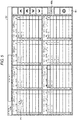
- FIG. 2 illustrates an example of an operation screen displayed by the display unit 11.
- a display area of one square is assigned per one order and a menu name and the number of orders included in each of orders are displayed in each of display areas.
- a table number, an order time, the number of customers, and waiter's identifier are respectively displayed so as to identify each of orders.
- a user can check a current order status and perform cooking of an ordered menu.
- the user can perform operations of the order display screen G1 in a non-contact manner. For example, when cooking or the like of an ordered menu is ended, by performing an operation (e.g., gesture) for removing the menu, the user can remove the corresponding menu from the order display screen G1.
- an operation e.g., gesture
- the controller 12 removes the menu instructed by the removal operation from the order display screen G1.
- the controller 12 may represent the menu which is a removal operation target with a broken line or the like (see menu M61 in FIG. 2 ). It is assumed that the order display screen G1 is configured so that a user can instruct various processes by moving the pointer P1 and selecting operators (e.g., menu, button, and the like).
- the communication unit 13 is a communication device performing wired or wireless communication.
- the communication unit 13 communicates with an order terminal (not illustrated) provided in a store and receives order information transmitted from the order terminal.
- This order terminal is, for example, carried by a salesperson and transmits order information input by the salesperson to the communication unit 13.
- a table number, an order time, the number of customers, contact information of a salesperson who is in charge of a customer, and the like are included in addition to the menu name and the number of orders.
- the motion recognition unit 14 includes a computer configuration such as a CPU, a GPU, a ROM, a RAM, and the like, various sensing devices, a wireless communication interface, and the like and recognizes a predetermined motion (e.g., gesture) performed by a user.
- the motion recognition unit 14 functions as the operation support unit 20 together with the controller 12 and receives an operation input for a screen displayed on the display unit 11 in a non-contact manner.
- the motion recognition unit 14 receives an operation input for a screen displayed on the display unit 11 in a non-contact manner. For example, when the removal operation of the menu described above is recognized, by cooperating with the display unit 11, the motion recognition unit 14 removes the menu instructed by the removal operation from the order display screen G1.
- the controller 12 and the motion recognition unit 14 are separated from each other.
- the embodiments of the present disclosure are not limited thereto, and the controller 12 and the motion recognition unit 14 may be integrally configured with a common computer configuration.
- the motion recognition unit 14 may be configured to recognize a face or a motion (for example, hand motion) of a user from a captured image of the user captured by an image capturing unit such as a charge coupled device (CCD) camera and an infrared camera.
- the communication unit 13 is replaced with the image capturing unit, and the motion recognition unit 14 determines whether or not the motion performed by the user corresponds to which gesture based on setting information indicating various types of gestures stored in ROM or the like of the motion recognition unit 14. Then, in a case where the motion of the user corresponds to any gesture, the motion recognition unit 14 recognizes that the gesture is performed by the user.
- a technique related to Intel Real Sense® or the like can be used.
- the motion recognition unit 14 may be configured to recognize operation of a user together with a measurement value measured by a measuring device 30 attached to an arm (in particular, wrist) of the user.
- the measuring device 30 has various sensors for measuring, for example, acceleration, an angular velocity, earth magnetism, and the like.
- the measuring device 30 is attached to a specific part of a user which is a measurement target. The specific part is, for example, the user's arm, wrist, finger, head, leg, or the like.
- the measuring device 30 (30a, 30b, and 30c) is attached to the user's wrist.
- the measuring device 30 transmits acceleration or an angular velocity of a hand of the user wearing the measuring device 30 to the motion recognition unit 14 as a measurement value by wireless communication.
- the motion recognition unit 14 which receives the measurement value determines whether or not a motion of the user corresponding to the measurement value corresponds to which gesture based on setting information indicating various types of gestures stored in ROM or the like of the motion recognition unit 14. Then, in a case where the motion of the user corresponds to any gesture, the motion recognition unit 14 recognizes that the gesture is performed by the user.
- the measuring device 30 is used and the measuring device 30 is attached to the user's wrist.
- FIG. 3 illustrates an example of the functional configuration included in the operation input device 1.
- the operation support unit 20 includes an operation start motion recognition unit 21, a display controller 22, an operation receiving unit 23, and an operation end motion recognition unit 24 as functional units.
- a part or all of these functional units may be a software configuration implemented using a RAM in cooperation with a processor (CPU or GPU) of either or both of the controller 12 and the motion recognition unit 14 and a program stored in a memory such as a ROM.
- a part or all of these functional units may be a hardware configuration implemented by one or a plurality of processing circuits or the like designed to perform each of functions.
- the operation start motion recognition unit 21 recognizes an operation start motion and identifies the user performing the motion. In addition, by giving operation authority to the user performing the operation start motion, the operation start motion recognition unit 21 validates an operation input to a screen displayed by the display unit 11.
- the operation start motion is not limited thereto and an arbitrary operation can be set to the operation start motion.
- a hand raising gesture followed by a gesture such as a finger snap may be the operation start motion.
- the finger snap means a motion of lightly snapping a thumb and other fingers (e.g., middle finger and the like) in a gripping form.
- the operation start motion recognition unit 21 recognizes that the user performs the operation start motion based on setting information defining the operation start motion stored in ROM or the like.
- identification method of an operator is not limited thereto and can adopt various methods.
- the measuring device 30 by causing the measuring device 30 to output a unique identifier assigned to each of measuring devices 30 together with a measurement value, a user wearing the measuring device 30 is identified based on the identifier.
- a user who instructs a start of operation may be identified through face recognition.
- the operation start motion recognition unit 21 performs exclusive control so that the number of users who operate an operation screen is one by preventing operation authority from being given to the other users.
- the display controller 22 displays various operation screens (GUI) and information related to operation of the operation input device 1 on the display unit 11. For example, the display controller 22 displays the order display screen G1 (see FIG. 2 ) or the like described above on the display unit 11.
- GUI operation screens
- the display controller 22 displays the order display screen G1 (see FIG. 2 ) or the like described above on the display unit 11.
- the display controller 22 changes a display form of the operation screen for each of operators. Specifically, the display controller 22 changes a display form of the order display screen G1 for each user to whom operation authority is given by the operation start motion recognition unit 21.
- a changing method of the display form is not limited thereto and can adopt various methods .
- the display controller 22 may change a background color of the order display screen G1 for each user to whom operation authority is given.
- FIG. 5 illustrates another example of the order display screen G1 displayed by the display unit 11 and corresponds to FIG. 2 .
- the order display screen G1 illustrated in FIG. 5 corresponds to a status in which operation authority is given to a user different from the order display screen G1 illustrated in FIG. 2 and has a background color different from the order display screen G1 (see 40a in FIG. 2 and 40b in FIG. 5 ) . It is assumed that the background color of the order display screen G1 is predetermined in advance for each user and is maintained as setting information.
- the display controller 22 may change the background color of the order display screen G1 to the color of the measuring device 30 attached to a user whose operation input is validated. Accordingly, it is possible to easily distinguish which user is operating, that is, which user's operation is reflected on a screen by the background color of the order display screen G1.
- a target of changing a display color is not limited to a background of the order display screen G1.
- a display color of the pointer P1 displayed inside the order display screen G1 may be changed for each user.
- the display color of the pointer P1 is predetermined in advance for each user and is stored as setting information. Accordingly, it is possible to easily distinguish which user is operating, that is, which user's operation is reflected on a screen by the display color of the pointer P1.
- the display controller 22 may change a shape of the pointer P1 displayed inside the order display screen G1 for each user to whom operation authority is given.
- the shape of the pointer P1 is predetermined in advance for each user and is stored as setting information. Accordingly, it is possible to easily distinguish which user is operating by the shape of the pointer P1.
- the display controller 22 may display user information such as a user name, a salesperson code, a face image, and the like representing a user to whom operation authority is given on the order display screen G1.
- user information such as a user name, a salesperson code, a face image, and the like representing a user to whom operation authority is given on the order display screen G1.
- the user information of each user is predetermined in advance for each user and is maintained as setting information. Accordingly, it is possible to easily distinguish which user is operating, that is, which user's operation is reflected on a screen by the user information displayed on the order display screen G1.
- the operation receiving unit 23 monitors a motion of a user to whom operation authority is given.
- the operation receiving unit 23 receives an operation corresponding to the motion.
- the operation receiving unit 23 determines whether or not the motion of the user corresponds to the predetermined motion.
- the operation receiving unit 23 receives the operation corresponding to the motion. For example, when the user moves his or her hand in either of up, down, left, or right direction, the operation receiving unit 23 receives this movement direction as an operation instructing a movement of the pointer P1.
- the operation receiving unit 23 receives this motion as an operation of selection or button press.
- the operation end motion recognition unit 24 recognizes the operation end motion. In addition, by releasing operation authority to the user performing the operation end motion, the operation end motion recognition unit 24 invalidates an operation input to a screen displayed by the display unit 11.
- the operation end motion is not limited thereto and an arbitrary operation can be set to the operation end motion in the same manner as the operation start motion.
- performing operation such as finger striking may be an operation end motion.
- the operation end motion recognition unit 24 recognizes that the user performs the operation end motion based on setting information indicating the operation end motion stored in ROM or the like.
- the display controller 22 restores an operation screen displayed on the display unit 11 to a default display form, that is, a display form indicating that no user can operate any operation. For example, in a case where a background color of the order display screen G1 is changed, the display controller 22 restores the background color to a default background color. In addition, for example, in a case where a display color or a shape of the pointer P1 is changed, the display controller 22 removes display of the pointer P1 or restores the display color or the shape to a default display color or a default shape. In addition, for example, in a case where user information is displayed, the display controller 22 removes display of the user information or displays information indicating that no operator exists instead of the user information.
- FIG. 6 is a flowchart illustrating an example of an operation support process executed by the operation input device 1.
- an operation screen is displayed on the display unit 11 in a default display form by control of the display controller 22.
- the operation start motion recognition unit 21 waits until an operation start motion is performed by any user (step S11; No) .
- the operation start motion recognition unit 21 identifies the user performing the operation start motion (step S12).
- the operation start motion recognition unit 21 gives operation authority to the user identified in step S12 and validates operation for an operation screen (step S13).
- the display controller 22 changes a display form of the operation screen according to the user to whom operation authority is given (step S14).
- the operation support unit 20 waits until the user to whom operation authority is given performs a predetermined motion (step S15; No).
- the operation support unit 20 determines whether or not the motion is an operation end motion (step S16).
- step S15 In a case where a predetermined motion other than the operation end motion is recognized in step S16 (step S15; Yes -> step S16; No), the operation receiving unit 23 receives an operation corresponding to the predetermined motion (step S17). Then, by cooperating with the controller 12, the operation receiving unit 23 executes a process in accordance with the operation (step S18) and the process returns to step S15. For example, in a case where removal operation of a menu is performed, by cooperating with the controller 12, the operation receiving unit 23 removes the menu selected by the removal operation from the order display screen G1 in step S18.
- step S16 when an operation end motion is recognized in step S16 (step S16; Yes), the operation end motion recognition unit 24 releases operation authority given to the user and invalidates an operation input for the operation screen (step S19). Then, the display controller 22 changes the display form of the operation screen to a default display form (step S20) and returns to step S11.
- the operation input device 1 of the present embodiment makes the display form of the operation screen displayed on the display unit 11 different from each other for each of operators. As a result, in the operation input device 1, it is possible to easily distinguish which user's operation is reflected on a screen by operation of the plurality of users in a non-contact manner even in a case where the operation screen displayed on the display unit 11 is operated.
- an exclusive process of operation authority is performed so that only one user operates the operation screen, but the present embodiment is not limited thereto.
- a plurality of users can simultaneously operate the operation screen.
- the operation start motion recognition unit 21 gives operation authority to each user performing the operation start motion.
- the display controller 22 changes the display form of the operation screen for each user to whom operation authority is given. Specifically, the display controller 22 makes the display color and the shape of the pointer P1 operated by the user different or makes the display color different when an operator such as a menu or the like is selected for each user to whom operation authority is given. Accordingly, it is possible to easily distinguish that which user's operation is reflected on a screen even in a case where the plurality of users simultaneously operates the operation screen displayed on the display unit 11.
Landscapes
- Engineering & Computer Science (AREA)
- General Engineering & Computer Science (AREA)
- Theoretical Computer Science (AREA)
- Human Computer Interaction (AREA)
- Physics & Mathematics (AREA)
- General Physics & Mathematics (AREA)
- User Interface Of Digital Computer (AREA)
- Position Input By Displaying (AREA)
Abstract
Description
- Embodiments described herein relate generally to a display system operable in a non-contact manner.
- In the related art, there is a technique for recognizing a motion (e.g., gesture) of a user's hands, fingers, and the like in a non-contact manner based on a measurement value obtained from a sensor attached to a specific body part such as the user's arm (in particular, wrist). According to the technique, a pointer disposed on a screen of a personal computer (PC) or the like is moved corresponding to the recognized motion, and an operation corresponding to a position of the pointer can be performed. With such a display system operable in a non-contact manner, since the system can be operable without a user touching any object, the operation can be carried out hygienically.
- However, in a situation where multiple users are authorized to operate the display system, it may be difficult for each user to recognize which user's operation is reflected on a screen.
- To this end, there is provided a display system operable in a non-contact manner, comprising: a display; a wireless communication module; a plurality of user-wearable devices, each of which is attachable to or around a user's hand, associated with a unique identifier, and is configured to detect a hand gesture made by the user's hand and wirelessly transmit data corresponding to the detected hand gesture to the wireless communication module along with the unique identifier; and a control device configured to: activate operation of the display by one of the user-wearable devices, upon the wireless communication module receiving data of a first predetermined hand gesture from said one of the user-wearable devices; control the display to display a display element unique to said one of the user-wearable devices, upon activation of the operation thereby; and change display contents of the display while the operation is activated, based on data of a second predetermined hand gesture transmitted from said one of the user-wearable devices and received by the wireless communication module.
- Preferably, the display element includes a background screen.
- Preferably, a color of the background screen is unique to said one of the user-wearable devices.
- Preferably, the display element includes a pointer.
- Preferably, at least one of a color and a shape of the pointer is unique to said one of the user-wearable devices.
- Preferably, the display element includes a display area indicating user attribute information.
- Preferably, the control device activates the operation by said one of the user-wearable devices, when operation by no other user-wearable devices are activated.
- Preferably, the control device is further configured to deactivate the operation of the display by said one of the user-wearable devices, upon the wireless communication module receiving data of a third predetermined hand gesture along with the unique identifier from said one of the user-wearable devices.
- The present invention further relates to a display system operable in a non-contact manner, comprising: a display; a wireless communication module; an image capturing device; and a control device configured to: biometrically authenticate a user through an image of the user captured by the image capturing device; activate operation of the display by the user, upon the image capturing device capturing an image of a first predetermined gesture made by the user; control the display to display a display element unique to the user, upon activation of the operation by the user; and change display contents of the display while the operation is activated, upon the image capturing device capturing an image of a second predetermined gesture made by the user.
- Preferably, the display element includes a background screen.
- Preferably, a color of the background screen is unique to the user.
- Preferably, the display element includes a pointer.
- Preferably, at least one of a color and a shape of the pointer is unique to the user.
- Preferably, the display element includes a display area indicating user attribute information.
- Preferably, the control device activates the operation by the user, when operation by no other users is activated.
- Preferably, the control device is further configured to deactivate the operation of the display by the user, upon the image capturing device capturing an image of a third predetermined gesture made by the user.
- The present invention further relates to a method for operating a display device in a non-contact manner, comprising: detecting, by a user-wearable device attached to or around a user's hand, a first predetermined hand gesture made by the user's hand; wirelessly transmitting data corresponding to the first predetermined hand gesture along with a unique identifier of the user-wearable device, from the user-wearable device to a wireless communication module coupled to a display device; activating operation of the display by the user-wearable device, upon the wireless communication module receiving the data of the first predetermined hand gesture along with the unique identifier; controlling the display device to display a display element unique to the user-wearable device, upon activation of the operation thereby; and changing display contents of the display device based on data of a second predetermined hand gesture that is wirelessly transmitted along with the unique identifier from the user-wearable device and received by the wireless communication module.
- Preferably, the operation by the user-wearable device is activated when no user-wearable device is activated.
- The method may further comprise: deactivating the operation of the display by the user-wearable device, upon the wireless communication module receiving data of a third predetermined hand gesture along with the unique identifier from the user-wearable device.
- The method may further comprise: while the operation by the user-wearable device is activated, prevent activating operation of the display by other user-wearable devices, even upon the wireless communication module receiving data of the first predetermined hand gesture from said other user-wearable devices.
-
-
FIG. 1 illustrates a configuration of an operation input device according to an embodiment. -
FIG. 2 illustrates an example of an operation screen displayed by a display unit. -
FIG. 3 illustrates a configuration of functional units included in the operation input device according to the embodiment. -
FIG. 4 illustrates an example of a gesture. -
FIG. 5 illustrates another example of the operation screen displayed by the display unit. -
FIG. 6 is a flowchart illustrating an example of an operation support process executed by the operation input device according to the embodiment. - An exemplary embodiment provides a non-contact operation input device capable of easily distinguishing that which user's operation is reflected on a screen.
- In general, according to an embodiment, a display system operable in a non-contact manner includes a display, a wireless communication module, a plurality of user-wearable devices, and a control device. Each of the user-wearable devices is attachable to or around a user's hand, associated with a unique identifier, and is configured to detect a hand gesture made by the user's hand and wirelessly transmit data corresponding to the detected hand gesture to the wireless communication module along with the unique identifier. The control device is configured to activate operation of the display by one of the user-wearable devices, upon the wireless communication module receiving data of a first predetermined hand gesture from said one of the user-wearable devices, control the display to display a display element unique to said one of the user-wearable devices, upon activation of the operation thereby, and change display contents of the display while the operation is activated, based on data of a second predetermined hand gesture transmitted from said one of the user-wearable devices and received by the wireless communication module.
- Hereinafter, an operation input device and a program according to an exemplary embodiment of the present disclosure will be described in detail with reference to the drawings. In the embodiment described below, an embodiment of the present disclosure is applied to a kitchen display for displaying order contents that is used in a store such as restaurants, but embodiments of the present disclosure is not limited to the embodiment.
-
FIG. 1 illustrates a configuration of anoperation input device 1 according to an embodiment. As illustrated inFIG. 1 , theoperation input device 1 includes adisplay unit 11, acontroller 12, acommunication unit 13, and amotion recognition unit 14. Thecontroller 12, thecommunication unit 13, and themotion recognition unit 14 may be integrated with thedisplay unit 11 or may be configured as separate units. - The
display unit 11 includes a display device such as a liquid crystal display (LCD), an organic electro luminescence (EL), or the like. Thedisplay unit 11 is located at a back office such as a kitchen or the like and displays various kinds of information such as a menu name, under control of thecontroller 12. In the present embodiment, since it is assumed that a plurality of users (e.g., cooks, salespersons, and the like) operates thesame display unit 11, it is preferable that thedisplay unit 11 is located at a position (for example, above a wall or the like) at which the plurality of users can simultaneously observe. - The
controller 12 includes a computer configuration such as a central processing unit (CPU), a graphics processing unit (GPU), a read only memory (ROM), a random access memory (RAM), and the like, and controls operation of theoperation input device 1. In addition, thecontroller 12 functions as anoperation support unit 20 together with themotion recognition unit 14 and controls a screen to be displayed on thedisplay unit 11. - Specifically, the
controller 12 performs control so as to cause thedisplay unit 11 to display various operation screens (graphical user interface (GUI)) or information according to operation of theoperation input device 1. For example, thecontroller 12 stores and manages order information received by thecommunication unit 13 and causes thedisplay unit 11 to display an order display screen on which a menu name, the number of orders, a table number, and the like included in the order information are displayed. -
FIG. 2 illustrates an example of an operation screen displayed by thedisplay unit 11. In an order display screen G1 illustrated inFIG. 2 , a display area of one square is assigned per one order and a menu name and the number of orders included in each of orders are displayed in each of display areas. In addition, in an upper part of each of the display areas, a table number, an order time, the number of customers, and waiter's identifier are respectively displayed so as to identify each of orders. - By seeing the order display screen G1 displayed on the
display unit 11, a user can check a current order status and perform cooking of an ordered menu. In addition, by using a function of themotion recognition unit 14 described below, the user can perform operations of the order display screen G1 in a non-contact manner. For example, when cooking or the like of an ordered menu is ended, by performing an operation (e.g., gesture) for removing the menu, the user can remove the corresponding menu from the order display screen G1. - In a case where removal of the menu is performed, for example, by performing a predetermined gesture such as moving a hand, the user moves a pointer P1 of a cursor or the like on a menu to be removed and selects the menu. Then, by moving the pointer P1 on a removal button B1 and selecting (e.g., by pressing) the removal button B1, the user instructs removal of the selected menu. When the removal operation of the menu described above is recognized by the
motion recognition unit 14, thecontroller 12 removes the menu instructed by the removal operation from the order display screen G1. Here, thecontroller 12 may represent the menu which is a removal operation target with a broken line or the like (see menu M61 inFIG. 2 ). It is assumed that the order display screen G1 is configured so that a user can instruct various processes by moving the pointer P1 and selecting operators (e.g., menu, button, and the like). - Returning to
FIG. 1 , thecommunication unit 13 is a communication device performing wired or wireless communication. Thecommunication unit 13 communicates with an order terminal (not illustrated) provided in a store and receives order information transmitted from the order terminal. This order terminal is, for example, carried by a salesperson and transmits order information input by the salesperson to thecommunication unit 13. In the order information, a table number, an order time, the number of customers, contact information of a salesperson who is in charge of a customer, and the like are included in addition to the menu name and the number of orders. - The
motion recognition unit 14 includes a computer configuration such as a CPU, a GPU, a ROM, a RAM, and the like, various sensing devices, a wireless communication interface, and the like and recognizes a predetermined motion (e.g., gesture) performed by a user. In the present embodiment, themotion recognition unit 14 functions as theoperation support unit 20 together with thecontroller 12 and receives an operation input for a screen displayed on thedisplay unit 11 in a non-contact manner. - Specifically, by recognizing a gesture which is a predetermined motion by a user and cooperating with the
controller 12, themotion recognition unit 14 receives an operation input for a screen displayed on thedisplay unit 11 in a non-contact manner. For example, when the removal operation of the menu described above is recognized, by cooperating with thedisplay unit 11, themotion recognition unit 14 removes the menu instructed by the removal operation from the order display screen G1. In the present embodiment, thecontroller 12 and themotion recognition unit 14 are separated from each other. However, the embodiments of the present disclosure are not limited thereto, and thecontroller 12 and themotion recognition unit 14 may be integrally configured with a common computer configuration. - A method for recognizing operation of a user is not particularly limited, and any technique of related art can be employed. The
motion recognition unit 14 may be configured to recognize a face or a motion (for example, hand motion) of a user from a captured image of the user captured by an image capturing unit such as a charge coupled device (CCD) camera and an infrared camera. In this case, thecommunication unit 13 is replaced with the image capturing unit, and themotion recognition unit 14 determines whether or not the motion performed by the user corresponds to which gesture based on setting information indicating various types of gestures stored in ROM or the like of themotion recognition unit 14. Then, in a case where the motion of the user corresponds to any gesture, themotion recognition unit 14 recognizes that the gesture is performed by the user. As such a configuration, for example, a technique related to Intel Real Sense® or the like can be used. - In addition, for example, as illustrated in
FIG. 1 , themotion recognition unit 14 may be configured to recognize operation of a user together with a measurement value measured by a measuringdevice 30 attached to an arm (in particular, wrist) of the user. The measuringdevice 30 has various sensors for measuring, for example, acceleration, an angular velocity, earth magnetism, and the like. In addition, the measuringdevice 30 is attached to a specific part of a user which is a measurement target. The specific part is, for example, the user's arm, wrist, finger, head, leg, or the like. InFIG. 1 , the measuring device 30 (30a, 30b, and 30c) is attached to the user's wrist. - In a case of being attached to the user's wrist, the measuring
device 30 transmits acceleration or an angular velocity of a hand of the user wearing the measuringdevice 30 to themotion recognition unit 14 as a measurement value by wireless communication. Themotion recognition unit 14 which receives the measurement value determines whether or not a motion of the user corresponding to the measurement value corresponds to which gesture based on setting information indicating various types of gestures stored in ROM or the like of themotion recognition unit 14. Then, in a case where the motion of the user corresponds to any gesture, themotion recognition unit 14 recognizes that the gesture is performed by the user. In the present embodiment, the measuringdevice 30 is used and the measuringdevice 30 is attached to the user's wrist. - Next, a functional configuration of the
operation input device 1 will be described.FIG. 3 illustrates an example of the functional configuration included in theoperation input device 1. As illustrated inFIG. 3 , theoperation support unit 20 includes an operation startmotion recognition unit 21, adisplay controller 22, anoperation receiving unit 23, and an operation endmotion recognition unit 24 as functional units. A part or all of these functional units may be a software configuration implemented using a RAM in cooperation with a processor (CPU or GPU) of either or both of thecontroller 12 and themotion recognition unit 14 and a program stored in a memory such as a ROM. In addition, a part or all of these functional units may be a hardware configuration implemented by one or a plurality of processing circuits or the like designed to perform each of functions. - When a gesture instructing a start of operation is performed by any one user, the operation start
motion recognition unit 21 recognizes an operation start motion and identifies the user performing the motion. In addition, by giving operation authority to the user performing the operation start motion, the operation startmotion recognition unit 21 validates an operation input to a screen displayed by thedisplay unit 11. - Here, the operation start motion is not limited thereto and an arbitrary operation can be set to the operation start motion. For example, as illustrated in
FIG. 4A , a hand raising gesture followed by a gesture such as a finger snap may be the operation start motion. Here, the finger snap means a motion of lightly snapping a thumb and other fingers (e.g., middle finger and the like) in a gripping form. In a case where the motion of a user corresponds to an operation start motion, the operation startmotion recognition unit 21 recognizes that the user performs the operation start motion based on setting information defining the operation start motion stored in ROM or the like. - In addition, identification method of an operator is not limited thereto and can adopt various methods. In the present embodiment, by causing the measuring
device 30 to output a unique identifier assigned to each of measuringdevices 30 together with a measurement value, a user wearing the measuringdevice 30 is identified based on the identifier. In addition, in a case of a configuration in which a motion is detected using a captured image, a user who instructs a start of operation may be identified through face recognition. During giving operation authority to one user, even if another user performs an operation start motion, the operation startmotion recognition unit 21 performs exclusive control so that the number of users who operate an operation screen is one by preventing operation authority from being given to the other users. - The
display controller 22 displays various operation screens (GUI) and information related to operation of theoperation input device 1 on thedisplay unit 11. For example, thedisplay controller 22 displays the order display screen G1 (seeFIG. 2 ) or the like described above on thedisplay unit 11. - In addition, the
display controller 22 changes a display form of the operation screen for each of operators. Specifically, thedisplay controller 22 changes a display form of the order display screen G1 for each user to whom operation authority is given by the operation startmotion recognition unit 21. A changing method of the display form is not limited thereto and can adopt various methods . For example, as illustrated inFIG. 5 , thedisplay controller 22 may change a background color of the order display screen G1 for each user to whom operation authority is given. - Here,
FIG. 5 illustrates another example of the order display screen G1 displayed by thedisplay unit 11 and corresponds toFIG. 2 . The order display screen G1 illustrated inFIG. 5 corresponds to a status in which operation authority is given to a user different from the order display screen G1 illustrated inFIG. 2 and has a background color different from the order display screen G1 (see 40a inFIG. 2 and 40b inFIG. 5 ) . It is assumed that the background color of the order display screen G1 is predetermined in advance for each user and is maintained as setting information. In this case, for example, by setting a different color to a color of the measuringdevice 30 attached to each of the user, thedisplay controller 22 may change the background color of the order display screen G1 to the color of the measuringdevice 30 attached to a user whose operation input is validated. Accordingly, it is possible to easily distinguish which user is operating, that is, which user's operation is reflected on a screen by the background color of the order display screen G1. - A target of changing a display color is not limited to a background of the order display screen G1. For example, a display color of the pointer P1 displayed inside the order display screen G1 may be changed for each user. In this case, it is assumed that the display color of the pointer P1 is predetermined in advance for each user and is stored as setting information. Accordingly, it is possible to easily distinguish which user is operating, that is, which user's operation is reflected on a screen by the display color of the pointer P1.
- In addition, for example, the
display controller 22 may change a shape of the pointer P1 displayed inside the order display screen G1 for each user to whom operation authority is given. In this case, it is assumed that the shape of the pointer P1 is predetermined in advance for each user and is stored as setting information. Accordingly, it is possible to easily distinguish which user is operating by the shape of the pointer P1. - In addition, for example, the
display controller 22 may display user information such as a user name, a salesperson code, a face image, and the like representing a user to whom operation authority is given on the order display screen G1. In this case, it is assumed that the user information of each user is predetermined in advance for each user and is maintained as setting information. Accordingly, it is possible to easily distinguish which user is operating, that is, which user's operation is reflected on a screen by the user information displayed on the order display screen G1. - The
operation receiving unit 23 monitors a motion of a user to whom operation authority is given. When recognizing that the user performs an operation start motion or a predetermined motion (e.g., gesture) other than an operation end motion described below, theoperation receiving unit 23 receives an operation corresponding to the motion. Specifically, theoperation receiving unit 23 determines whether or not the motion of the user corresponds to the predetermined motion. In a case where the motion of the user corresponds to the predetermined motion, theoperation receiving unit 23 receives the operation corresponding to the motion. For example, when the user moves his or her hand in either of up, down, left, or right direction, theoperation receiving unit 23 receives this movement direction as an operation instructing a movement of the pointer P1. In addition, when the user performs a motion such as finger snapping or the like, theoperation receiving unit 23 receives this motion as an operation of selection or button press. - When a gesture instructing an end of operation is performed by a user to whom operation authority is given by the operation start
motion recognition unit 21, the operation endmotion recognition unit 24 recognizes the operation end motion. In addition, by releasing operation authority to the user performing the operation end motion, the operation endmotion recognition unit 24 invalidates an operation input to a screen displayed by thedisplay unit 11. - Here, the operation end motion is not limited thereto and an arbitrary operation can be set to the operation end motion in the same manner as the operation start motion. For example, as illustrated in
FIG. 4B , after performing hand lowering operation, performing operation such as finger striking may be an operation end motion. In a case where a motion of a user corresponds to an operation end motion, the operation endmotion recognition unit 24 recognizes that the user performs the operation end motion based on setting information indicating the operation end motion stored in ROM or the like. - With release of operation authority, the
display controller 22 restores an operation screen displayed on thedisplay unit 11 to a default display form, that is, a display form indicating that no user can operate any operation. For example, in a case where a background color of the order display screen G1 is changed, thedisplay controller 22 restores the background color to a default background color. In addition, for example, in a case where a display color or a shape of the pointer P1 is changed, thedisplay controller 22 removes display of the pointer P1 or restores the display color or the shape to a default display color or a default shape. In addition, for example, in a case where user information is displayed, thedisplay controller 22 removes display of the user information or displays information indicating that no operator exists instead of the user information. - Hereinafter, an operation of the
operation input device 1 of the configuration described above will be described.FIG. 6 is a flowchart illustrating an example of an operation support process executed by theoperation input device 1. As a premise of the present process, it is assumed that an operation screen is displayed on thedisplay unit 11 in a default display form by control of thedisplay controller 22. - First, the operation start
motion recognition unit 21 waits until an operation start motion is performed by any user (step S11; No) . When recognizing that the operation start motion is performed by any user (step S11; Yes), the operation startmotion recognition unit 21 identifies the user performing the operation start motion (step S12). Next, the operation startmotion recognition unit 21 gives operation authority to the user identified in step S12 and validates operation for an operation screen (step S13). - Continuously, the
display controller 22 changes a display form of the operation screen according to the user to whom operation authority is given (step S14). Next, theoperation support unit 20 waits until the user to whom operation authority is given performs a predetermined motion (step S15; No). When the predetermined motion is performed by the user, theoperation support unit 20 determines whether or not the motion is an operation end motion (step S16). - In a case where a predetermined motion other than the operation end motion is recognized in step S16 (step S15; Yes -> step S16; No), the
operation receiving unit 23 receives an operation corresponding to the predetermined motion (step S17). Then, by cooperating with thecontroller 12, theoperation receiving unit 23 executes a process in accordance with the operation (step S18) and the process returns to step S15. For example, in a case where removal operation of a menu is performed, by cooperating with thecontroller 12, theoperation receiving unit 23 removes the menu selected by the removal operation from the order display screen G1 in step S18. - On the other hand, when an operation end motion is recognized in step S16 (step S16; Yes), the operation end
motion recognition unit 24 releases operation authority given to the user and invalidates an operation input for the operation screen (step S19). Then, thedisplay controller 22 changes the display form of the operation screen to a default display form (step S20) and returns to step S11. - As described above, the
operation input device 1 of the present embodiment makes the display form of the operation screen displayed on thedisplay unit 11 different from each other for each of operators. As a result, in theoperation input device 1, it is possible to easily distinguish which user's operation is reflected on a screen by operation of the plurality of users in a non-contact manner even in a case where the operation screen displayed on thedisplay unit 11 is operated. - While certain embodiments have been described, these embodiments have been presented by way of example only, and are not intended to limit the scope of the inventions. Indeed, the novel embodiments described herein may be embodied in a variety of other forms; furthermore, various omissions, substitutions and changes in the form of the embodiments described herein may be made without departing from the framework of the inventions. The accompanying claims and their equivalents are intended to cover such forms or modifications as would fall within the scope of the inventions.
- For example, in the embodiment described above, an exclusive process of operation authority is performed so that only one user operates the operation screen, but the present embodiment is not limited thereto. For example, a plurality of users can simultaneously operate the operation screen. In this case, the operation start
motion recognition unit 21 gives operation authority to each user performing the operation start motion. In addition, thedisplay controller 22 changes the display form of the operation screen for each user to whom operation authority is given. Specifically, thedisplay controller 22 makes the display color and the shape of the pointer P1 operated by the user different or makes the display color different when an operator such as a menu or the like is selected for each user to whom operation authority is given. Accordingly, it is possible to easily distinguish that which user's operation is reflected on a screen even in a case where the plurality of users simultaneously operates the operation screen displayed on thedisplay unit 11.
Claims (15)
- A display system operable in a non-contact manner, comprising:a display;a wireless communication module;a plurality of user-wearable devices, each of which is attachable to or around a user's hand, associated with a unique identifier, and is configured to detect a hand gesture made by the user's hand and wirelessly transmit data corresponding to the detected hand gesture to the wireless communication module along with the unique identifier; anda control device configured to:activate operation of the display by one of the user-wearable devices, upon the wireless communication module receiving data of a first predetermined hand gesture from said one of the user-wearable devices;control the display to display a display element unique to said one of the user-wearable devices, upon activation of the operation thereby; andchange display contents of the display while the operation is activated, based on data of a second predetermined hand gesture transmitted from said one of the user-wearable devices and received by the wireless communication module.
- The display system according to claim 1, wherein the display element includes a background screen.
- The display system according to claim 2, wherein a color of the background screen is unique to said one of the user-wearable devices.
- The display system according to any one of claims 1 to 3, wherein the display element includes a pointer.
- The display system according to claim 4, wherein at least one of a color and a shape of the pointer is unique to said one of the user-wearable devices.
- The display system according to any one of claims 1 to 5, wherein the display element includes a display area indicating user attribute information.
- The display system according to any one of claims 1 to 6, wherein the control device activates the operation by said one of the user-wearable devices, when operation by no other user-wearable devices are activated.
- The display system according to any one of claims 1 to 7, wherein
the control device is further configured to deactivate the operation of the display by said one of the user-wearable devices, upon the wireless communication module receiving data of a third predetermined hand gesture along with the unique identifier from said one of the user-wearable devices. - A display system operable in a non-contact manner, comprising:a display;a wireless communication module;an image capturing device; anda control device configured to:biometrically authenticate a user through an image of the user captured by the image capturing device;activate operation of the display by the user, upon the image capturing device capturing an image of a first predetermined gesture made by the user;control the display to display a display element unique to the user, upon activation of the operation by the user; andchange display contents of the display while the operation is activated, upon the image capturing device capturing an image of a second predetermined gesture made by the user.
- The display system according to claim 9, wherein the display element includes a pointer and at least one of a color and a shape of the pointer is unique to the user.
- The display system according to claim 9 or 10, wherein
the control device is further configured to deactivate the operation of the display by the user, upon the image capturing device capturing an image of a third predetermined gesture made by the user. - A method for operating a display device in a non-contact manner, comprising:detecting, by a user-wearable device attached to or around a user's hand, a first predetermined hand gesture made by the user's hand;wirelessly transmitting data corresponding to the first predetermined hand gesture along with a unique identifier of the user-wearable device, from the user-wearable device to a wireless communication module coupled to a display device;activating operation of the display by the user-wearable device, upon the wireless communication module receiving the data of the first predetermined hand gesture along with the unique identifier;controlling the display device to display a display element unique to the user-wearable device, upon activation of the operation thereby; andchanging display contents of the display device based on data of a second predetermined hand gesture that is wirelessly transmitted along with the unique identifier from the user-wearable device and received by the wireless communication module.
- The method according to claim 12, wherein
the operation by the user-wearable device is activated when no user-wearable device is activated. - The method according to claim 12 or 13, further comprising:deactivating the operation of the display by the user-wearable device, upon the wireless communication module receiving data of a third predetermined hand gesture along with the unique identifier from the user-wearable device.
- The method according to any one of claims 12 to 14, further comprising:while the operation by the user-wearable device is activated, prevent activating operation of the display by other user-wearable devices, even upon the wireless communication module receiving data of the first predetermined hand gesture from said other user-wearable devices.
Applications Claiming Priority (1)
| Application Number | Priority Date | Filing Date | Title |
|---|---|---|---|
| JP2016173078A JP6776067B2 (en) | 2016-09-05 | 2016-09-05 | Operation input device and program |
Publications (1)
| Publication Number | Publication Date |
|---|---|
| EP3291059A1 true EP3291059A1 (en) | 2018-03-07 |
Family
ID=59702597
Family Applications (1)
| Application Number | Title | Priority Date | Filing Date |
|---|---|---|---|
| EP17187883.8A Withdrawn EP3291059A1 (en) | 2016-09-05 | 2017-08-25 | Display system operable in a non-contact manner |
Country Status (3)
| Country | Link |
|---|---|
| US (1) | US20180067562A1 (en) |
| EP (1) | EP3291059A1 (en) |
| JP (1) | JP6776067B2 (en) |
Families Citing this family (5)
| Publication number | Priority date | Publication date | Assignee | Title |
|---|---|---|---|---|
| US10185401B2 (en) * | 2016-09-29 | 2019-01-22 | Intel Corporation | Determination of cursor position on remote display screen based on bluetooth angle of arrival |
| CN113359971A (en) * | 2020-03-06 | 2021-09-07 | 中光电创境股份有限公司 | Display control method, display control system and wearable device |
| US11416079B2 (en) | 2020-12-03 | 2022-08-16 | Motorola Mobility Llc | Snap motion gesture detection and response |
| US11769134B2 (en) | 2021-03-22 | 2023-09-26 | International Business Machines Corporation | Multi-user interactive ad shopping using wearable device gestures |
| WO2023210164A1 (en) * | 2022-04-26 | 2023-11-02 | 住友電気工業株式会社 | Animation operation method, animation operation program, and animation operation system |
Citations (4)
| Publication number | Priority date | Publication date | Assignee | Title |
|---|---|---|---|---|
| US20080136775A1 (en) * | 2006-12-08 | 2008-06-12 | Conant Carson V | Virtual input device for computing |
| US20130265229A1 (en) * | 2012-04-09 | 2013-10-10 | Qualcomm Incorporated | Control of remote device based on gestures |
| US20140266597A1 (en) * | 2013-03-15 | 2014-09-18 | Tyfone, Inc. | Personal digital identity device with motion sensor responsive to user interaction |
| US20150346892A1 (en) * | 2010-02-23 | 2015-12-03 | Muv Interactive Ltd. | System for projecting content to a display surface having user-controlled size, shape and location/direction and apparatus and methods useful in conjunction therewith |
Family Cites Families (20)
| Publication number | Priority date | Publication date | Assignee | Title |
|---|---|---|---|---|
| JP2986671B2 (en) * | 1994-02-01 | 1999-12-06 | 三菱電機株式会社 | Order display device, serving form management device, and order management device |
| JPH09269963A (en) * | 1996-04-03 | 1997-10-14 | Mitsubishi Electric Corp | Service system for restaurants by meal ticket method |
| JP4058602B2 (en) * | 2000-12-04 | 2008-03-12 | 株式会社タック | Dining room service system |
| JP4587245B2 (en) * | 2000-12-27 | 2010-11-24 | 株式会社タック | Self-service restaurant service system |
| US8555207B2 (en) * | 2008-02-27 | 2013-10-08 | Qualcomm Incorporated | Enhanced input using recognized gestures |
| JP2009258914A (en) * | 2008-04-15 | 2009-11-05 | Canon Inc | Information processor and program and information processing system |
| WO2010009418A1 (en) * | 2008-07-18 | 2010-01-21 | Wei Gu | Systems and methods for controlling computers and devices |
| JP5120136B2 (en) * | 2008-08-05 | 2013-01-16 | ブラザー工業株式会社 | Display control apparatus, remote controller used for the display control apparatus, and video conference system |
| JP5151868B2 (en) * | 2008-09-30 | 2013-02-27 | ブラザー工業株式会社 | Display control device and video conference system. |
| JP2010277176A (en) * | 2009-05-26 | 2010-12-09 | Ricoh Co Ltd | Information processing apparatus, information processing system, and information processing method |
| US20110199303A1 (en) * | 2010-02-18 | 2011-08-18 | Simpson Samuel K | Dual wrist user input system |
| US9218058B2 (en) * | 2011-06-16 | 2015-12-22 | Daniel Bress | Wearable digital input device for multipoint free space data collection and analysis |
| WO2013061156A2 (en) * | 2011-10-27 | 2013-05-02 | Cell Rox, Ltd. | Systems and method for implementing multiple personas on mobile technology platforms |
| CN104145481B (en) * | 2012-01-03 | 2018-04-13 | Lg电子株式会社 | Image display device and method for operating same |
| JP5916566B2 (en) * | 2012-08-29 | 2016-05-11 | アルパイン株式会社 | Information system |
| JP6019947B2 (en) * | 2012-08-31 | 2016-11-02 | オムロン株式会社 | Gesture recognition device, control method thereof, display device, and control program |
| US8990734B2 (en) * | 2012-10-15 | 2015-03-24 | Nextep Systems, Inc. | Method and assembly for displaying menu options |
| JP2015099574A (en) * | 2013-11-20 | 2015-05-28 | 株式会社東芝 | Recognition device, recognition method, recognition program, and terminal device |
| US10444849B2 (en) * | 2014-09-01 | 2019-10-15 | Yinbo Li | Multi-surface controller |
| US9864434B2 (en) * | 2016-03-30 | 2018-01-09 | Huami Inc. | Gesture control of interactive events using multiple wearable devices |
-
2016
- 2016-09-05 JP JP2016173078A patent/JP6776067B2/en not_active Expired - Fee Related
-
2017
- 2017-08-11 US US15/675,132 patent/US20180067562A1/en not_active Abandoned
- 2017-08-25 EP EP17187883.8A patent/EP3291059A1/en not_active Withdrawn
Patent Citations (4)
| Publication number | Priority date | Publication date | Assignee | Title |
|---|---|---|---|---|
| US20080136775A1 (en) * | 2006-12-08 | 2008-06-12 | Conant Carson V | Virtual input device for computing |
| US20150346892A1 (en) * | 2010-02-23 | 2015-12-03 | Muv Interactive Ltd. | System for projecting content to a display surface having user-controlled size, shape and location/direction and apparatus and methods useful in conjunction therewith |
| US20130265229A1 (en) * | 2012-04-09 | 2013-10-10 | Qualcomm Incorporated | Control of remote device based on gestures |
| US20140266597A1 (en) * | 2013-03-15 | 2014-09-18 | Tyfone, Inc. | Personal digital identity device with motion sensor responsive to user interaction |
Also Published As
| Publication number | Publication date |
|---|---|
| JP6776067B2 (en) | 2020-10-28 |
| JP2018041164A (en) | 2018-03-15 |
| US20180067562A1 (en) | 2018-03-08 |
Similar Documents
| Publication | Publication Date | Title |
|---|---|---|
| US20180067562A1 (en) | Display system operable in a non-contact manner | |
| US20170038838A1 (en) | Information processing system and information processing method | |
| JP2021039789A5 (en) | ||
| EP2990911A1 (en) | Gesture-controlled computer system | |
| CN112154402A (en) | Wearable device and its control method, gesture recognition method and control system | |
| US20140022171A1 (en) | System and method for controlling an external system using a remote device with a depth sensor | |
| JP2004078977A (en) | Interface device | |
| JP6341343B2 (en) | Information processing system, information processing apparatus, control method, and program | |
| JP2018073287A5 (en) | ||
| US10437415B2 (en) | System, method, and device for controlling a display | |
| WO2016073938A1 (en) | Transit vending machine with automatic user interface adaption | |
| JPWO2018198272A1 (en) | Control device, information processing system, control method, and program | |
| US20130234997A1 (en) | Input processing apparatus, input processing program, and input processing method | |
| KR101233793B1 (en) | Virtual mouse driving method using hand motion recognition | |
| US10823964B2 (en) | Work assistance apparatus, work assistance method, and computer-readable, non-transitory recording medium recording work assistance program executed by computer | |
| EP2843516A2 (en) | Improved touch detection for a touch input device | |
| JP5062898B2 (en) | User interface device | |
| KR20150082746A (en) | Hand measurement system to order customized golf gloves | |
| JP6446967B2 (en) | Information processing apparatus, information processing method, and program | |
| JP2013089187A (en) | Display device and display method | |
| JP6289655B2 (en) | Screen operation apparatus and screen operation method | |
| JP6074403B2 (en) | System, program, and method capable of pointer operation on head mounted display by touch panel type device | |
| JP2015122124A (en) | Information apparatus with data input function by virtual mouse | |
| WO2019039065A1 (en) | Information processing device, information processing method, and program | |
| KR101381366B1 (en) | Apparatus for gesture recognition remote controller and operating method for the same |
Legal Events
| Date | Code | Title | Description |
|---|---|---|---|
| PUAI | Public reference made under article 153(3) epc to a published international application that has entered the european phase |
Free format text: ORIGINAL CODE: 0009012 |
|
| STAA | Information on the status of an ep patent application or granted ep patent |
Free format text: STATUS: THE APPLICATION HAS BEEN PUBLISHED |
|
| AK | Designated contracting states |
Kind code of ref document: A1 Designated state(s): AL AT BE BG CH CY CZ DE DK EE ES FI FR GB GR HR HU IE IS IT LI LT LU LV MC MK MT NL NO PL PT RO RS SE SI SK SM TR |
|
| AX | Request for extension of the european patent |
Extension state: BA ME |
|
| STAA | Information on the status of an ep patent application or granted ep patent |
Free format text: STATUS: REQUEST FOR EXAMINATION WAS MADE |
|
| 17P | Request for examination filed |
Effective date: 20180907 |
|
| RBV | Designated contracting states (corrected) |
Designated state(s): AL AT BE BG CH CY CZ DE DK EE ES FI FR GB GR HR HU IE IS IT LI LT LU LV MC MK MT NL NO PL PT RO RS SE SI SK SM TR |
|
| STAA | Information on the status of an ep patent application or granted ep patent |
Free format text: STATUS: EXAMINATION IS IN PROGRESS |
|
| 17Q | First examination report despatched |
Effective date: 20190315 |
|
| STAA | Information on the status of an ep patent application or granted ep patent |
Free format text: STATUS: THE APPLICATION HAS BEEN WITHDRAWN |
|
| 18W | Application withdrawn |
Effective date: 20190708 |